Monthly Archives: February 2020
Alnabreac Water Tower – the Prototype
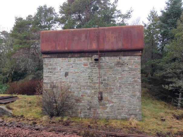
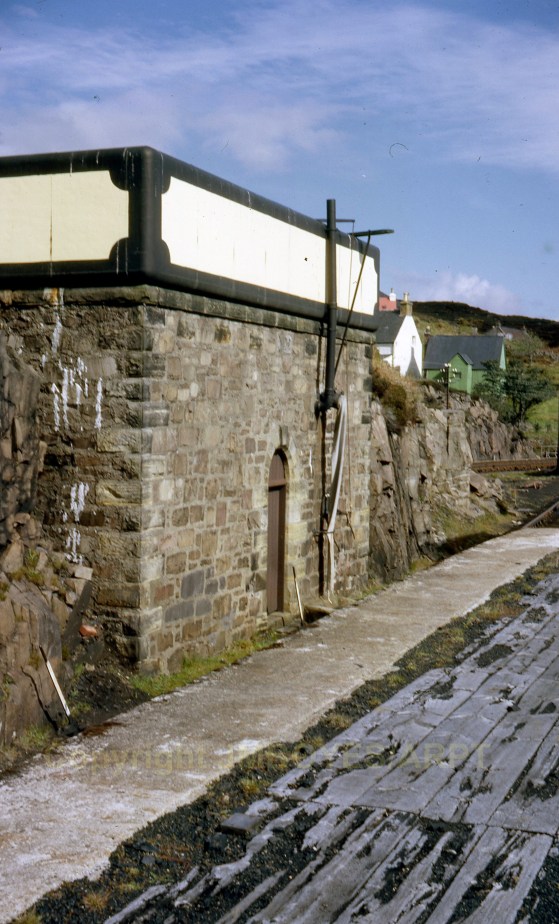
The smaller of the two water towers I am building is a model of the tower that the Highland Railway built at Altnabreac. Altnabreac is around 12 miles from the nearest paved road so even though it has not been used for approaching 60 years, it has proved too expensive to realise its scrap vale.
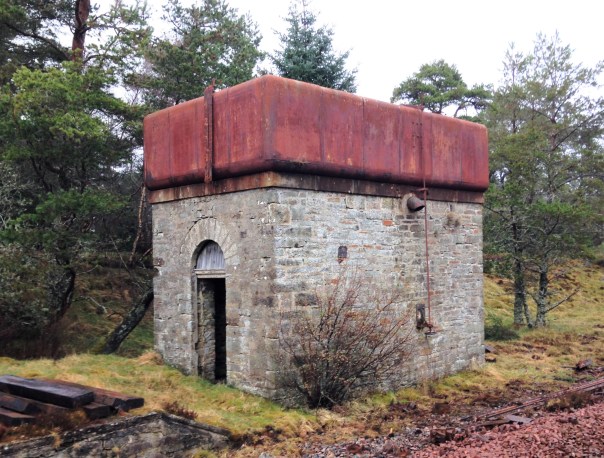
What is possibly even more remarkable, you can see the paint – including the detailing at the corners – which probably dates from the LMS era; how much original pre-1948 paint is still out there?
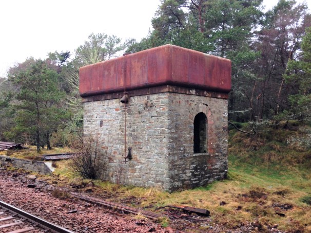
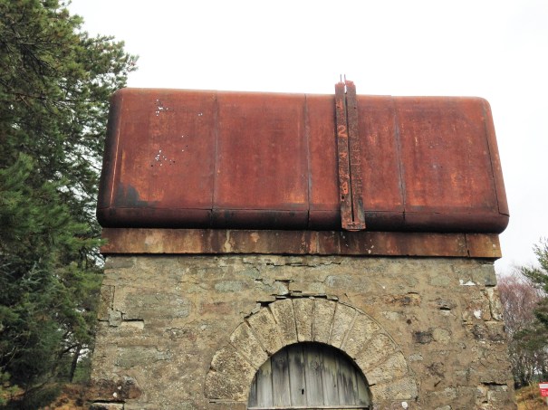
Being able to get up close to the tank, it can be seen that it is made out of sections; there are quarter segments for the corners and then straight panels for the sides. They obviously came as a kit of parts and could be built to a size to suit the requirement. Thus, I note that the Altnabreac is the same width wide as the Kyle tank was deep – so I can determine how many panels were used to make the Kyle version. Whilst the lines are fient, they are there and I will replicate them with a hint of a score on the plasticard.
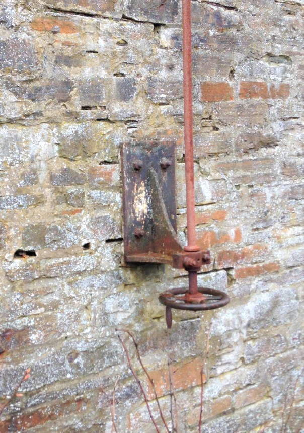
A float inside the tank was used to transmit the water level to this gauge on the exterior.
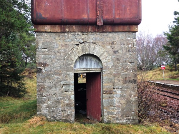
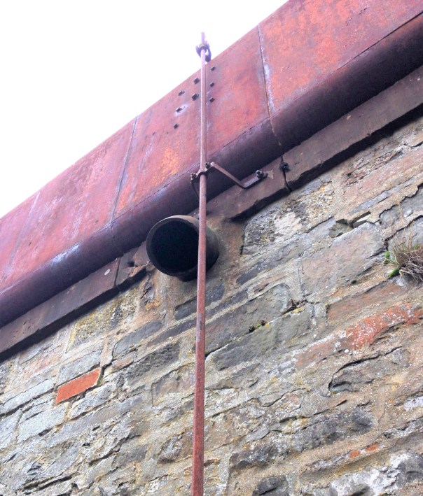
The tank as a whole is remarkably intact – the only elements I can positively identify is missing is the delivery bag which will have been of hessian and the wooden windows. However, I suspect there are two other elements that have now been removed. There was probably an access ladder at one end to reach the interior of the tank but leaving it in situ would to be dangerous, hence its removal. Furthermore, there is no sign of any heating to the tank. Whilst the largish body of water will have taken a while to freeze, the region around Altnabreac is well-known for its cold temperatures so I suspect there is a boiler inside with a flue through the tank. The outlet valve is controlled by a wheel at low level connected with a rod with a thread at its head. This connects to one end of a lever that has a threaded nut in order to transfer the movement into the interior of the tank where the valve is located.
A drawing of the water tank can be found at this link: Altnabreac Water Tower or if you are a member of the Highland Railway Society it will be in the next Journal and subsequently from their drawing service.
The other water tank I am building is a model of Kyle of Lochalsh’s water tank. Eddie Bellis drew this and his drawing is in the November 1975 edition of the Railway Modeller. There are couple of pictures of in LMS Engine Sheds: Volume 6 by the Oxford Publishing Co. The only other Highland Railway water tower that has been drawn that I know of is Garves, which Henry Orbach drew – it is in a 1950s Model Railway Constructor or was reprinted in my fathers The Dingwall & Skye Railway.

Let there be water……..part 1
Part of the concept of the back-story for Glenmutchkin is that it is at the end of a long line so that locos need to be serviced and it was also at the foot of a steep gradient, so trains need to be banked out of the station. All this is creates a lot of thirsty locomotives that would have needed servicing and attention – so it will have a busy motive power depot.
The Highland Railway’s water tanks tended to be of a similar style with a tank made of sectional components and rounded head, base and corners. There is nothing available from any of the manufacturers so it was obvious these need to be scratchbuilt.
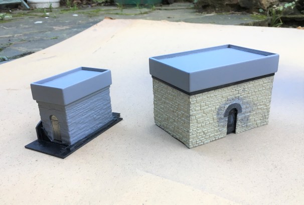
There remains one tank of this type still in situ, at Altnabreac which I will describe in the next post. In addition to this, there are drawings from Eddie Bellis of the Kyle’s water tower and also of Garve by Henry Orbach. I have elected to build a pair – one of Kyle and one of Altnabreac (the latter being the smaller).
Kyle’s water tank from the early post steam era. Photograph with permission from Armstrong Railway Photographic Trust, JM Boyes collection.
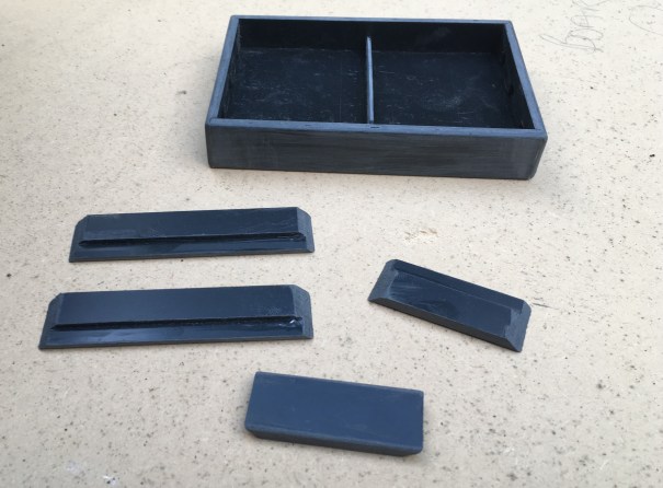
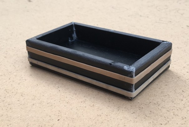
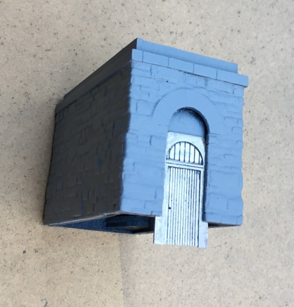
Starting with the tanks, I laminated a series of strips of plasticard to the right height and then used a belt sander to put the chamfer on these before then making them up into a box.
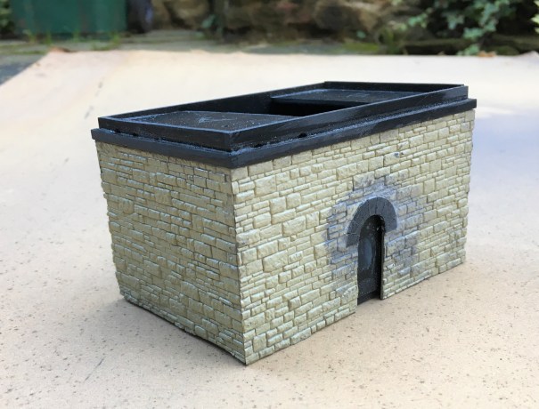
As with most of my stone buildings, I use Wills random stone plastic sheets; now available from Peco. On far too many occasions I see this used with panels butted against each other; either on corners or even worse on the flat. Unless the stones are toothed into each other, this screams as being incorrect even to a layman. Therefore, it is best to form corners either from a sheet cut vertically and then chamfer the inside faces so that the coursing is retained for its full length even on the cut face.
This means that courses line up from side to front without any silly jumps, as can be seen below. This technique can not be used in all examples and sometimes it is necessary to actually tooth panels into each other by cutting corresponding dog teeth into adjacent panels.
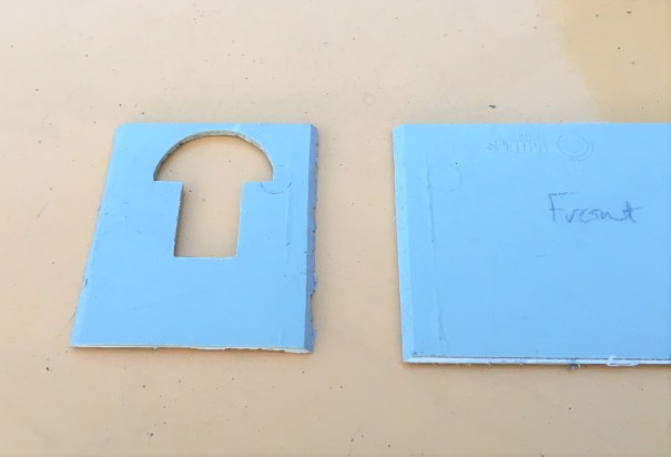
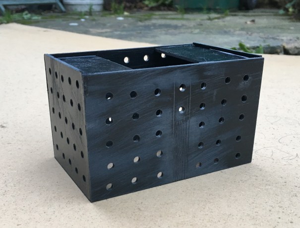
I find that the mortar courses on Wills sheets are a bit too deep and because lots of others use it its pattern is a little too obvious; so it looses its realism (or maybe I am just so sad that I can tell a material by its stone coursing!!). I get over this by part filling the mortar courses with a plastic filler – which is basically dissolved plastic in a solvent carrier (lovely and smely!). This tends to distort the sheets as it is only applied to one side so I first laminate the sheet to some thick (1.5 or 2mm plasticard). Due to the volumes of solvent to be sloshed around in constructing buildings in this manner, it is important to allow for the solvent to escape – regretfully I have a number of coach roofs which many years later have mushy sections where the solvent has been trapped and has distorted the plastic in its efforts to cut through it and escape! I thus drill regular holes or slots in the backing plasticard, which you can see here:
Whilst the desire to mask the coursing pattern on the Wills sheet might seem a fair amount of bother given the need to reinforce the walls with an inner laimanate, I think the effect is worth the effort. A blast of grey primer shows that the coursing and texture of the stone is retained but equaly it does not look like everyone else’s!
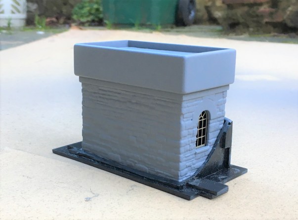
The use of the laminations does give the advantage that slots for window frames and doors can be created. These allow an etching to be slid in, either from below or behind. They can be slid out again for painting and make this aspect a breeze to do.
And this is where they have got to; the guts of both done but with a chunk of detailing and some basework still to be done.
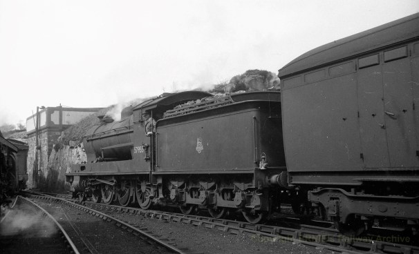
But lets sign this post off with a fine HC Casserley picture of a Superheated Goods using the MPD as a headshunt in the early 1950s. This photograph is used with permission and is now part of Ernie Brack’s collection. He has a substantial on line collection of photographs (including the JM Boyes collection) with a good proportion of them being of the Highland’s system – you can loose many an hour in his flickr site – this being a link to his Dingwall & Skye album.