Blog Archives
Alnabreac Water Tower – the Prototype
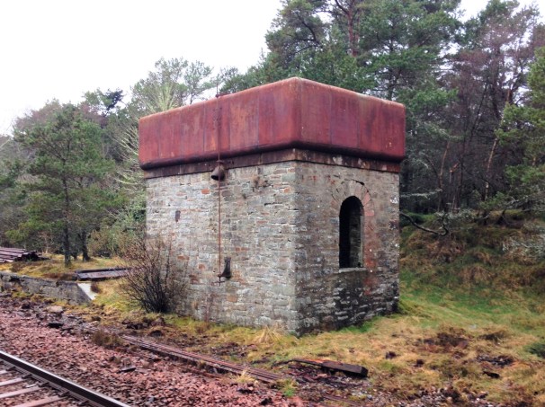
The smaller of the two water towers I am building is a model of the tower that the Highland Railway built at Altnabreac. Altnabreac is around 12 miles from the nearest paved road so even though it has not been used for approaching 60 years, it has proved too expensive to realise its scrap vale.
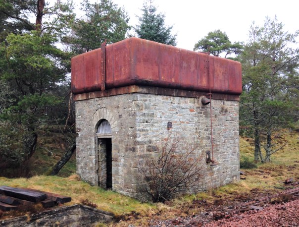
What is possibly even more remarkable, you can see the paint – including the detailing at the corners – which probably dates from the LMS era; how much original pre-1948 paint is still out there?
Being able to get up close to the tank, it can be seen that it is made out of sections; there are quarter segments for the corners and then straight panels for the sides. They obviously came as a kit of parts and could be built to a size to suit the requirement. Thus, I note that the Altnabreac is the same width wide as the Kyle tank was deep – so I can determine how many panels were used to make the Kyle version. Whilst the lines are fient, they are there and I will replicate them with a hint of a score on the plasticard.
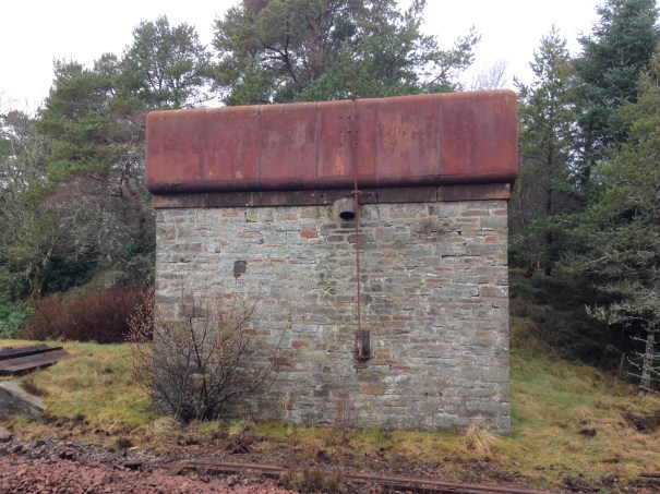
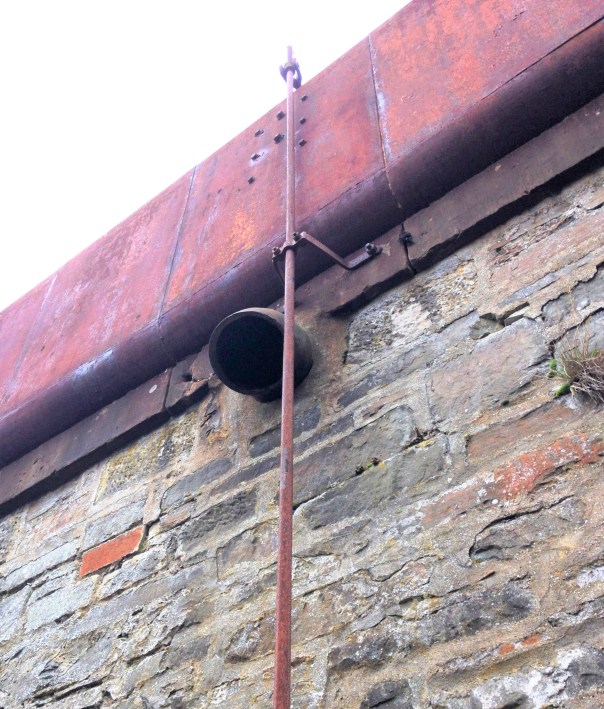
A float inside the tank was used to transmit the water level to this gauge on the exterior.
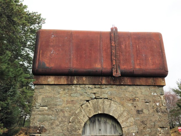
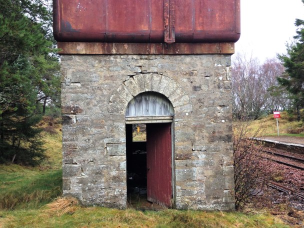
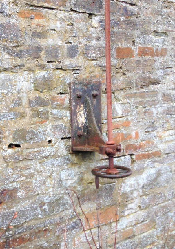
The tank as a whole is remarkably intact – the only elements I can positively identify is missing is the delivery bag which will have been of hessian and the wooden windows. However, I suspect there are two other elements that have now been removed. There was probably an access ladder at one end to reach the interior of the tank but leaving it in situ would to be dangerous, hence its removal. Furthermore, there is no sign of any heating to the tank. Whilst the largish body of water will have taken a while to freeze, the region around Altnabreac is well-known for its cold temperatures so I suspect there is a boiler inside with a flue through the tank. The outlet valve is controlled by a wheel at low level connected with a rod with a thread at its head. This connects to one end of a lever that has a threaded nut in order to transfer the movement into the interior of the tank where the valve is located.
A drawing of the water tank can be found at this link: Altnabreac Water Tower or if you are a member of the Highland Railway Society it will be in the next Journal and subsequently from their drawing service.
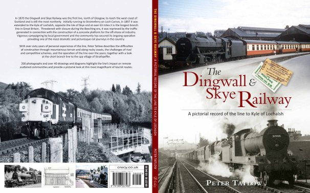
The other water tank I am building is a model of Kyle of Lochalsh’s water tank. Eddie Bellis drew this and his drawing is in the November 1975 edition of the Railway Modeller. There are couple of pictures of in LMS Engine Sheds: Volume 6 by the Oxford Publishing Co. The only other Highland Railway water tower that has been drawn that I know of is Garves, which Henry Orbach drew – it is in a 1950s Model Railway Constructor or was reprinted in my fathers The Dingwall & Skye Railway.

Lining Things Up….
As usual, I set off over the festive break with plans to do all sorts of things and failed to do any of them fully. One aspect that I did get moved forward though was the painting and lining of a couple of my six wheeled coaches.
Back in my youth, lining pens held no fear and I could genuinely dash off a fully lined coach in a few evenings. Thirty years of pushing a computer keyboard has dulled my drawing skills to the point where I am close to terrified to pick up a bow pen and I have not had the nerve to line a coach for a long time. I am confronting this fear in a couple of months by attending a class run by Ian Rathbone on painting and lining at Missenden Railway Modellers. In the meantime, however, I can still line utilising transfers, in this case those provided by Fox Transfers.
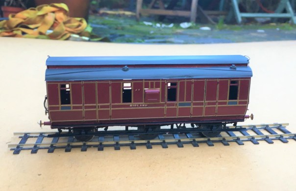
Being preformed in straight lines, these do work best for the square panelled beading of some of the Midland Clayton stock, like my dia 501 full brake. I had taken care in designing this with beading sizes that were correct (and matched the Fox Transfers). They thus work quite well I think.
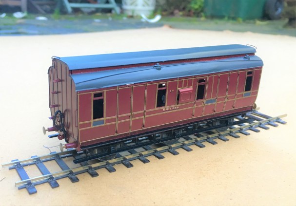
I deliberately left the handrails and door handles off at this stage to make the lining easier but the door hinges still created problems that I will need to touch in with acrylic paints; burnt ochre looks about right. I also still need to block in the black to the head and foot of the sides plus where the lengths of transfer where they crossed – I will do this with a Roting pen as I still feel confident enought to wield this!
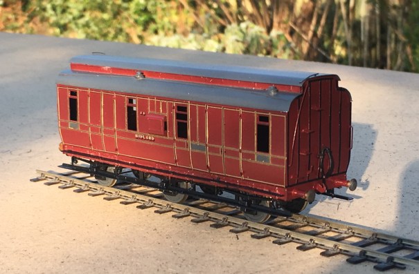
So there is still plenty to do, but I am dead chuffed with this and it will soon be finished and ready for service.
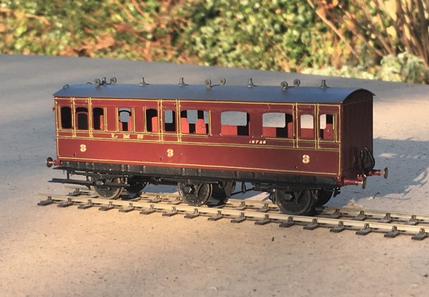
Second up is a Lochgorm Models third class saloon that has been waiting for its lining for rather longer. It is a more difficult prospect to line as it has round corners to the panels and, over the doors and windows, shallow arcs. These can’t be formed with transfers as these are straight. I have thus used the transfers for the straight sections and then brush painted the curved sections with cadmium yellow acrylic paint.
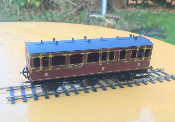
If all goes well, the Roting pen can then be used to infill the black to the centre and form the curves across the windows and doors. Lets see!

News from Miscellany Models
Followers of this blog will have noted that various test builds of my artwork coming together and I am now able to offer a number of these for sale under the name of Miscellany Models.
First up is a Highland Railway/LMS/BR diagram 51 full brake – priced at £48.00 for a 4mm and is suitable for OO, EM or P4. These were the last generation of full brake produced by the Highland, built with both cupboard doors and sliding doors as well as alternative forms of guards duckets (all of these are included in the kit). The kit inclusive of fully sprung Fox bogies (see below), roof, corridor connections (also see below) but all castings and buffers will need to be sourced separately. The castings for the bogies are proposed, but are not presently available.
As was common with many pre-grouping coaches these vehicles utilised Fox Bogies (£16.00) and these are being made separately to the remainder of the kit, These bogies have been developed in conjunction with Justin at Rumney Models and are fully sprung, with both the axleboxes and the bolsters sprung. They really do glide across track and look as if they weigh many tons rather than a few grams! They need castings for your favoured axleboxes/springs and bolsters but do include the foot steps and all of the bogies sides, brakes and details. Suitable for oo, EM and P4.
.JPG.3b26712c4490ad68695b10226612a0a9.JPG)
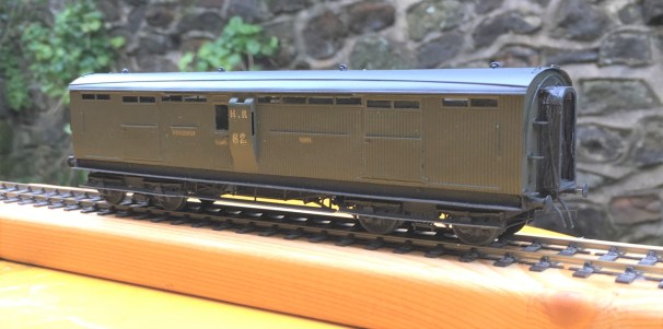
The second coach kit is for a MR/LMS/BR: Dia 530 Passenger Brake – priced at £36.00 in 4mm scale (suitable for OO, EM and P4). This prototype was built in some numbers and by the 1920s they were spread extensively across the LMS system. The kit is for full etches covering the roof, body, underframe and footboards plus parts for the sliding central axle included. It needs axlebox/springs (available from Branchlines or Coopercraft), gas lamps, buffers, brake and gas cylinders.
.JPG.1678157932a192d68328755d825c54f0.JPG)
On the wagon front, there is an etch to detail the NER/LNER/BR: Dia P7 Hopper Wagon – £13.50 4mm (sufficient for two wagons). They cater for a large number of the variants to this numerous and long lasting hopper wagon. Needs wheels and the Slaters kit P7 kit for the donor model. Variants that can be made include the end braked version, improved components for the Morton braked version, outside twin W irons and also the anti-friction wheel device.

All of these are available from my website https://miscellanymodels.com/ and in addition to this from the Rumney Models stand at the following shows – Scalefour North in April, Railex in May, Scalefourum in September and South Hants in November,
All of these have been extensively road tested by me with a couple of test builds for each of them. You can see this unfold on my blog and if you are interested in seeing how they go together do take a look!
Please remember that the availability of these models is an adjunct to my own hobby and this has to be accommodated within the constraints of my day job and general life! In particular I can’t get to post these orders until Saturdays so do please give me a little slack when it comes to getting the goods to you!

Highland Railway – Cradle Bolster
A long time ago, I showed that I had conceived a design for a pretty unusual vehicle in the Highland’s fleet, a cradle bolster. They gave this diagram no 25 and it has a square cradle that sits on the top of a fairly simple body. The cradle had four bolsters protruding from its corners and I anticipate it was used in conjunction with another bolster with the cradle rotating to allow the load to twist on curves. I presume it was conceived to support long but more flexible loads such as thin sheet steel/iron than a traditional bolster wagons could cater for.
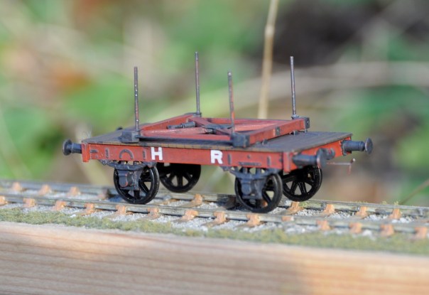
As this was my first attempt at designing vehicles, it is fair to say it went through a fair few iterations (or was that irritations!) which does largely explain why it has taken so long to complete from the first build – but it is now done and it looks pretty smart I reckon! It is really small in reality – being dwarfed by other even relative moderate wagons!
The second main complication has been as a result of the need to source castings for the axlebox/springs. I have used the Highland Railway Society’s but these do not come with attached springs (by design, so that they can be combined with differing springs to suit different situations). They are also not conceived to accommodate bearings sliding up and down within them and need to be ground out from the rear to make a slot for this. This makes them a bu**er to attach and therefore I am in the process of sorting out my own masters to overcome this problem. Once these are complete and I have got some castings done, I will produce a run of these for sale. So watch this space! I am also taking a look at the realities of scaling this up to 7mm, so also watch this space (but probably for longer before you will see anything!).
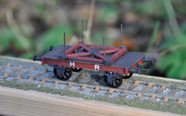
The error that I have had pointed out to me is that the bolsters ought to be tapered and now that I know this they do jar somewhat, so the next one will need to have this sorted out. As they lasted into well into the LMS days, there will be a second one and the one shown here will appear from time to time on Benfieldside jostling amongst the NER stuff!
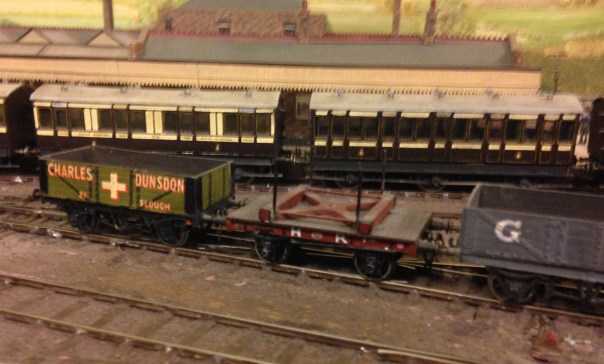
When I first embarked on this build, I thought that this was such an unusual subject that I was going to be building the first model example ever. A rather foolish notion that was upset by a visit to visit Buckingham a couple of years back where I see Peter Denny had modelled one (it is believed he was friends with Hutchinson, who had measured one up in the 1930/40s) – as you can see below. I have subsequently found out at least two others who have scratch built their own, so clearly I will need to search harder for originality!

Something Fishy…….
Fish was an important traffic to the Highland Railway and as a result fish trucks were one of their most numerous classes of wagons. Given that Glenmutchkin is conceived to be on the coast, fish traffic will also be an important feature on the model too. There is to be a line to an off-scene harbour, so that I can justify a significant traffic. I already have a shortish train of fish vehicles, mostly open trucks, but I definitely need more
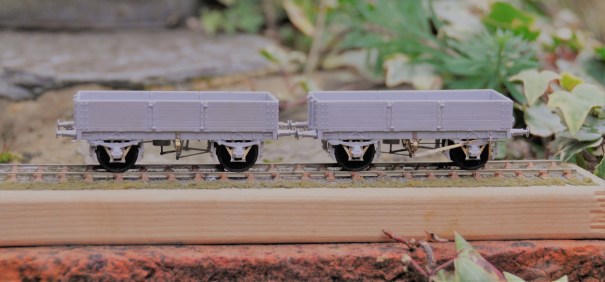
Back in April, I reviewed the Mousa Models LNWR covered van, which I was generally impressed with. Buoyed with this I spent portions of the last couple of weekends making a pair of the same manufacturer’s HR Drummond Fish Trucks. The kit is arranged for the variant that had a centre drop door, but there was an alternative variant with full length drop sides and at least some acquired morton brakes during their life. Thus, there are a few modifications that can be made if you wish.
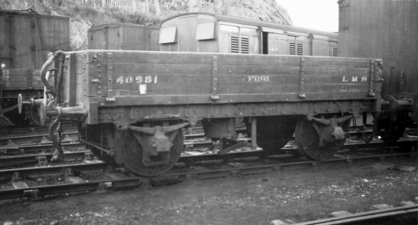
The above is a full drop side version of the fish truck at (I think) Kyle (AB McLeod, HRS Collection).
Having built a few Mousa Models kits and however regretful it is, I was not surprised to find there were no instructions included in the kit. This is a pain as there is enough going on with the model to justify some guidance and anyone who does not have my father’s book will struggle. Unfortunately, I did not take any mid way through photographs before I realised that some notes on its construction would be of assistance, but hopefully these notes and the pictures of the completed model will be helpful.
A first issue I discovered was that the resin casting was a touch distorted. The ends in particular bowed into the well of the wagon and the whole wagon had a slight twist to it. This is a common problem with resin kits but with care can easily be corrected. Put the body casting in hot water – as hot as you can tolerate with hands (so less than boiling – 40C is about right) and it softens sufficient to allow these to be corrected.
Although the resolution quality of the LNWR van was good, the quality of the prints that formed the masters for these resin castings was not nearly good enough. Significant portions of them looked as if they were sand castings and did not look real. The body sides were better and were capable of being improved to an acceptable standard with some work with wet and dry sand paper. The solebars were worse, possibly because they received less effort to tidy them up prior to being used as a master. I managed to tidy it up a bit more in the areas that were more free of rivet heads, but above the W irons this was not possible and will have to be masked with some weathering.
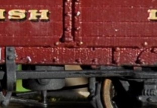
The roughness of the print is apparent to the solebar
The kit is conceived with sprung W-irons to Mousa Models normal design – details of the assembly of which can be found in my previous blog post. However, these need to be carefully lined up to the bolts on the outside of the solebars as the locating slots to the underside are oversized and allow too much slop. It is also necessary to use the Brassmasters axle spacing jig to ensure that the axles are parallel and correctly spaced.
As I noted previously, Mousa Models seem to wish to use resin parts for as much of their recent kits as possible. There were only a few parts where this was a problem on the LNWR van but the problem is rather worse on these fish trucks due to the additional elements of detail that they contain. Had some of the components been produced as etched parts, they would have been a lot more durable without compromising fidelity. I replaced the brake levers, coupling hooks, vacuum brake plunger and brake tie bars with etched components or wire but if I were doing any more of these, I would also swap the brake blocks/hangers because I have managed to damage two of these. Masokits do some that are suitable, although there may be others too that I do not know of.
Page 147 of the carriages and wagons book shows a drawing of how the Drummond patent brake levers operated. In this, it can be seen that there was a long lever running to the right hand end from the fulcrum of the “scotch brake”. This then met a smaller lever that operated in a cam arrangement on the long lever but also connected through a rod to the other side of the wagon. On this side, there was another short lever (so appeared on the left hand end on this side). In the kit, the brake lever is rather crude due to the need to beef it up so that it is durable but even then it is very vulnerable. Furthermore, there is a second long lever, which is not correct at all. Instead, I made up a rod from brass and utilised an etch from the Highland Railway Society.
The principal side to the wagons, showing the missing brake lever now provided by way of a Highland Railway Society etching.
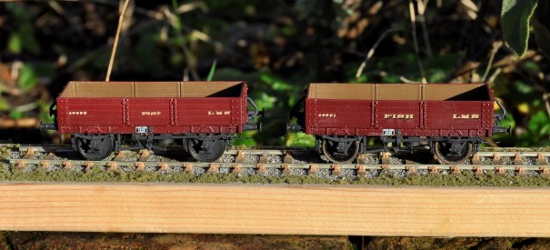
The patent braking system was, however, found to be unsafe because one side could be operated without the user on the other realising it (it cost someone some fingers, I believe) and the Board of Trade banned them for new construction. Therefore, many wagons had their braking arrangements changed, either by the use of full length levers and a ratchet or even a full change to morton brakes. I converted one of my wagons to the former by the use of some etched levers from 51L and an extra V hanger from the scrapbox.
And now the subsidiary side to the wagons, showing the Drummond Patent Brake lever to the left hand vehicle and a replacement long lever on the right hand vehicle.
I also took the view that the buffers were too delicate to survive in use and therefore swapped them for Drummond buffers available from the Highland Railway Society. I also found it necessary to cram the whole of the underside of the chassis with lead, to get the wagon’s weight to a level that would operate the wagon’s springs.
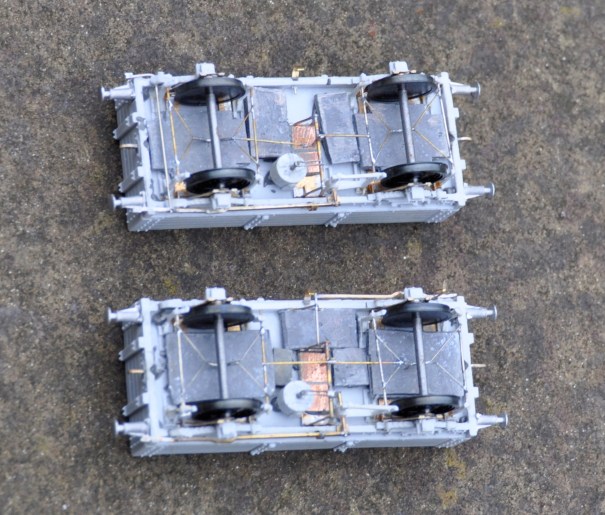
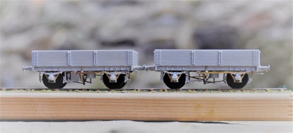
The underside – the rod to the Drummond brake is visible to the left hand end of the top vehicle.
Although these will have been green with yellow lettering for much of their lives, I chose to do them in LMS crimson lake. Rather fine they look too! When carrying fish boxes, it is known that turfs were used to provide thermal insulation around the fish for the journey but my guess is that this was covered within tarpaulins. I have tended to find that the paper tarpulians (Smiths etc) are not that durable so I need to do some experimenting on alternatives – I do have something in mind. That will be for another post though!
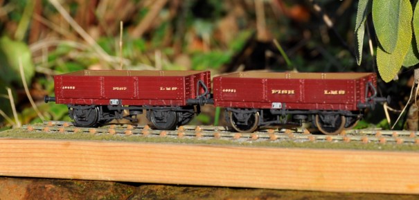
Painted (well I seem to have missed the rims!) and awaiting weathering
All in all, these are quite attractive vehicles, very core to the required stock for Portchullin and the kits are a pretty good – but they could be better and easier to build if Mousa models had dealt with what are relatively obvious points.
