Blog Archives

Midland Six Wheeled Full Brakes
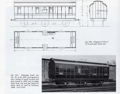
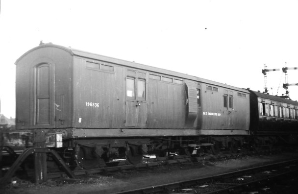
Although not Highland vehicles, these full brakes have a strong association with the Highland’s branchlines in the post grouping years. Once the LMS took over the Highland’s system in 1923, they seemed to have been horrified by the state of the coaching stock that they inherited! Portions of the Highland’s fleet were speedily retired and large numbers of foreign company’s stock was drafted onto the system (especially the main line from Perth to Inverness, where the trains became fully corridor connected almost overnight).
When it came to the branchlines, the upgrade came primarily by the cascading of the better Highland stock onto these lines but there were exceptions. Although the Highland had full brakes, it was a line that had a lot of parcels/packages traffic, so it seemed that they needed even more and a batch of these Midland six wheeled full brakes were drafted in.
Many photographs of the Highland branchlines of the 1920s had one lurking in the background so I felt one should get to make appearances on Glenmutchkin. Simple, I thought, Slaters do a plastic kit for one and whilst it is no longer available, it is easy to pick up second hand and it should be a nice quick build. Unfortunately, I had not realised what a rubbish kit it was! It is too short and too narrow, most of the mastering is really crude and the panelling in particular would be a scale 6 inches deep. So the Slaters kit made it back on ebay only marginally quicker than it came off and I set about designing my own kit.
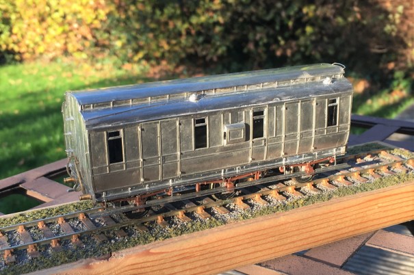
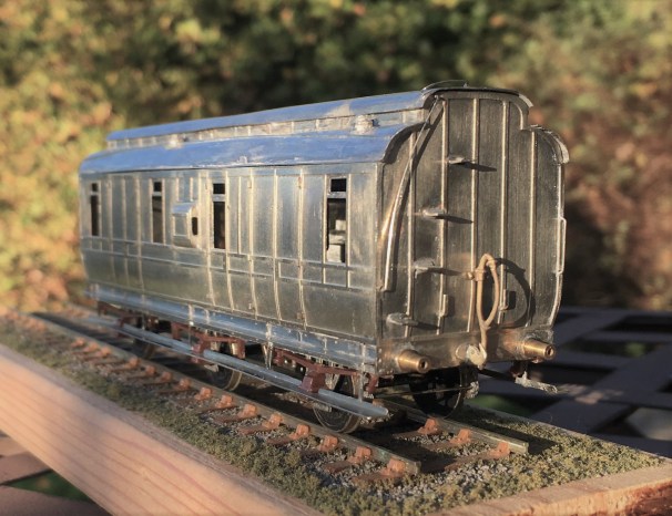
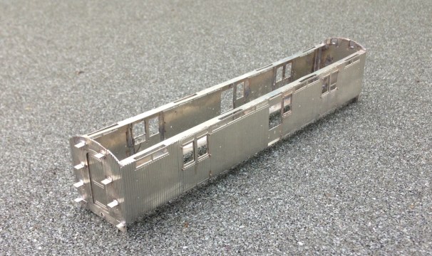
It has taken a couple of iterations and about three years, but finally I have got to the stage where I am happy with it but you can form your own view!
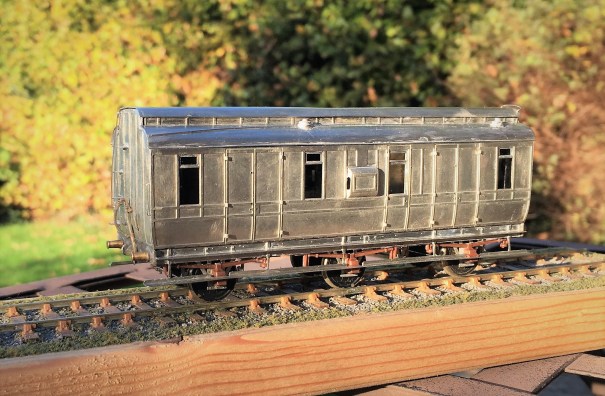
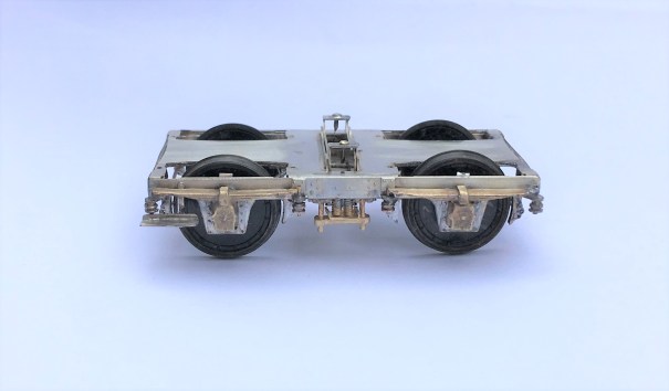
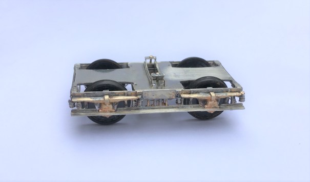
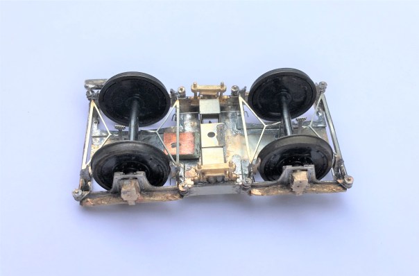
The first iteration used a cleminson chassis but in the light of the success I had with sliding axles on some of my other 6 wheeled stock, I redesigned it to include these and some sprung W-irons in the style of Bill Bedford’s.
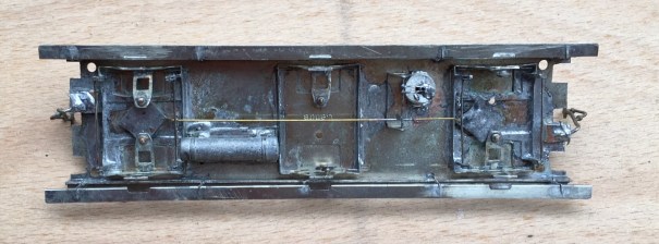
This proved similarly successful and as you can see in the video, it trundles along quite nicely!
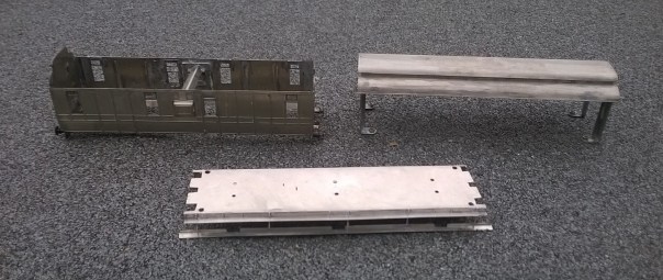
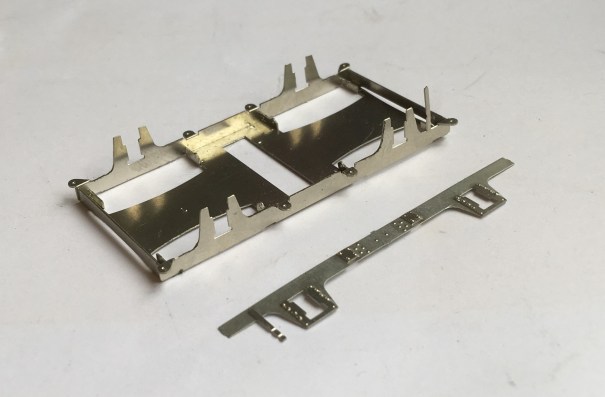
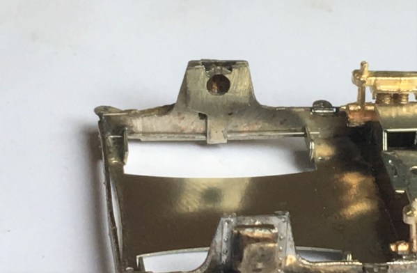
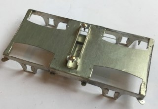
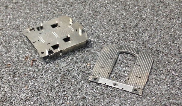
Other than the use of these sliding axles, the main unusual feature of the model is the arrangement of securing the roof. I have found that it is essential to bolt these in place to prevent the roof becoming adrift at some point in the future (which has happened to half my stock over time). Therefore, I designed a set of legs that allow the roof to be bolted through the floor from below and in the process also securing the separate chassis tight too. Broken down, the components look like this and having them separated does make painting a lot easier. It is definitely the route I will take in the future.
It is intended that this kit will be made available for sale as a 4mm/1ft model – albeit you will need to source the fittings/castings yourself. I have prepared some fairly extensive instructions (see link below) and this includes the details of what is required and where to get it from. I am waiting for a quote from the etching company to be able to work out the sensible cost for these; so an update post will follow when I list it on the Miscellany Models site.
Miscellany Models Rolling Stock 2 – Midland dia 530 Full Brake v2
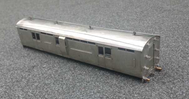
In the meantime, here are a couple of additional views of the completed vehicle, awaiting its turn in the paintshop!

Dia 51 Test Build – Fox Heavyweight Bogies
After the painting disaster, I have been working on the latest version of the Fox Bogies. The prototype utilised a patented design with pressed steel plates to form the sides and ends which produced a stiff and resilient frame, better than the other contemporary options. Thus these bogies were very common amongst the pre-grouping companies with most of using them to at least some degree.
Although there are several model manufacturers that produce Fox bogies, there are no versions that use springing which I now prefer. As they were the primary form of bogie used by the Highland Railway, I need a few of them and thus I have been putting some effort into getting a top notch solution. In this regard, I have been assisted greatly by Justin Newitt if Rumney Models whose design of sprung bogie has formed the basis of this.
The model has primary suspension on the pin points based on guitar wire springs,
In addition to this, the design has a sprung bolster, also based on a guitar string suspension.

The castings I have used on these are from Lochgorm Models and the design has been conceived to enable these to be used either retaining their dampers (the cylindrical appendage at the end of the leaf springs) or with replacements that are a little more defined.
The etch is also designed to be provided with full stepboards as below or with only a short section to one end – as they typically were converted to during their life.
There is full brake gear provided, with a little trick where they do not pass under the axle (remember this view is upside down!) – this enables the wheel to be removed if this is required.
This is not the first version of these (don’t accuse me of not test building my designs!) and they are very close to done. The final change is to adjust the primary spring hangers slightly so that they are not visible when they are depressed (you can just see it poking above the sides in line with the axlebox), The advantage of computer drawn artwork is that things like this can be changed relatively easily.
These, and indeed the rest of the dia 51 full brake, will be made available for sale quite soon.
Previous parts to the test build can be found here:
- part 1 – the main body shell of the cupboard door version
- part 2 – the underframe
- part 3 – the second one, the sliding door version

Dia 51 Full Brake – Test Build Part 1
Following the last delivery from the etchers, it was time to get on and do the first test builds. First up was the dia 51 Full Brake. This vehicle was one of the later coaches from the Highland Railway and was of similar design to the cove roof corridor coaches that have been available from Lochgorm Models for some time. They were also amongst some of the last highland coaches to service as tool vans etc. This is what one looked like late on in its career after its corridor connections had been removed.
As with my efforts for the scrap tank, I am seeking to try and be a bit smarter with some of the kit design to draw together ideas of assembly of my own and also those of others. So starting with the ends, these will be made with a double skin to both provide the footsteps and, less commonly, some tabs to allow the sides to be secured to them.
I have always found that too many etched coaches have flimsey sides that become distorted as they are made (or when ham-fisted me does anyway). Therefore, I have designed this such that the head and base of the side have significantly sized stiffening pieces, as can be seen below. These are designed to interlock with the tabs at the ends such that most of the locating of the parts is largely defined by the kits components.

Once the basics of the shell are together, this is what it looks like.
The roof proved to be one of the most challenging parts of the build. I had originally designed this with an inner to form the shape of the roof and then a thinly etched outer layer to go over this to provide the rainstrips and other detail. It proved too difficult to get the two to laminate well or even be rolled to a similar curve.
Instead, therefore, I ditched the outer layer and relied only on the inner. This had been half etched on the underside to assist its rolling to the curved profile. I found that it was still difficult to roll the roof due to the tightness of the curves at the extremity of the roof but by simply using bending bars it was quite easy to put the curves in with a limited amount of faceting. Faceting is where short straight sections with bends to the next short section that gives the impression of a curve. Once this was then filed on the outside to smooth out the facets, a smooth curve became pretty good. Thereafter, it was necessary to form the rainstrips with wire and file them back to square sections and as you can see, the effect is pretty convincing.
The underframe and bogies are to follow, in part 2.
Scrap Tank Test Build – Part 2; Continuing with the Body
The next stages of the test build were to do the footplate/tank sides/can exterior.
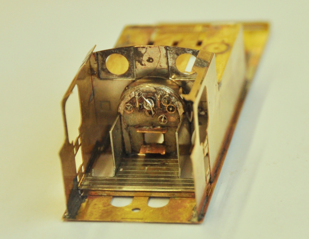
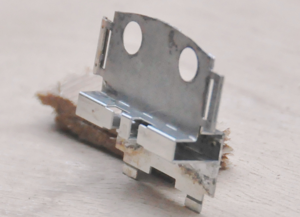
My initial design for the footplate is not particularly radical, but the test build has shown up that until the boiler is put in place (which comes some way into the build process) the front is somewhat delicate, irrespective of whether the footplate valences are fitted or not. Thus, in addition to the temporary stiffener that can be seen to the front of the footplate in the picture below, stiffeners will be provided to the front half of the footplates. The idea of these can be seen in the following view which shows the rear of the cab. By folding these over at 90o during the build, they give strength to the more delicate parts of components. Some will be incorporated into the finished article, others will simply be discarded when their job is done.
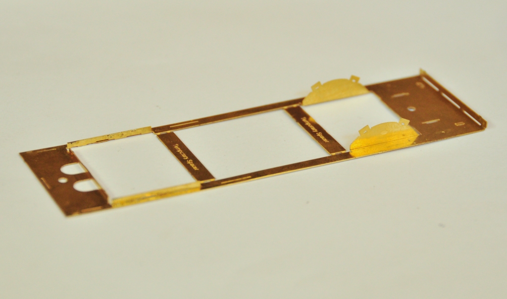
The two tanks, along with the sides to the cab/bunker, are conceived as a single piece (if you go back to my previous posting, you can see this in the flat in the etch). The two halves are separated by temporary spacers to both assist in locating them but also to give strength to the assembly prior to the fitting of the boiler which is where it will get its strength from. It was when I tackled this part, I reached the first disaster – the etchers had failed to half etch from behind so I was missing some fold lines. This was pretty frustrating as it entirely negated the intended efficiency of the design and even though I now have a corrected etch, I had to solder on by cutting the parts at the intended line of the half etch and soldering them together in the more traditional manner – exactly what my design was intended to avoid. As a result of this, there are no neat photos of the tanks being folded up and secured in place, we have to jump on a bit to see this.
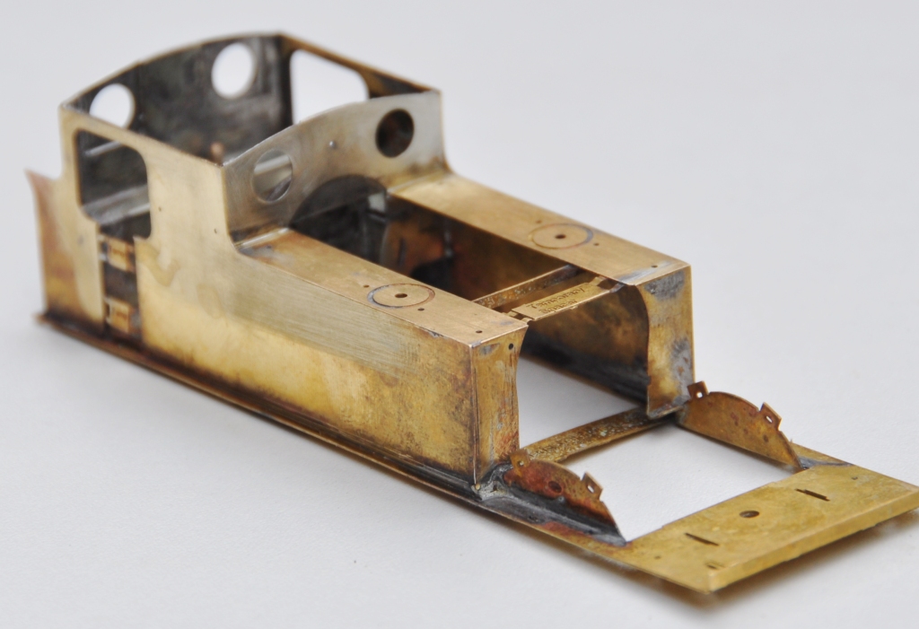
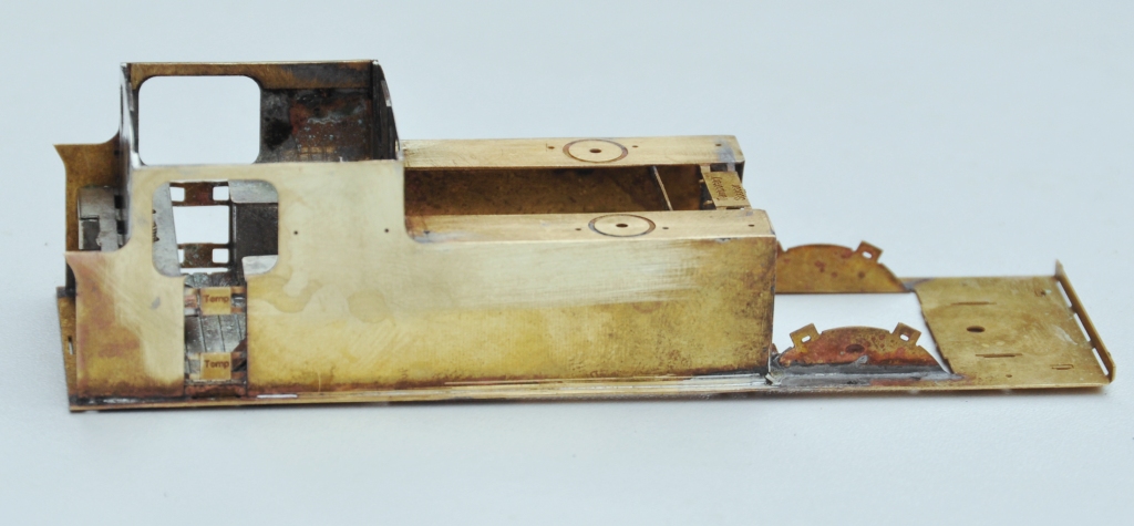
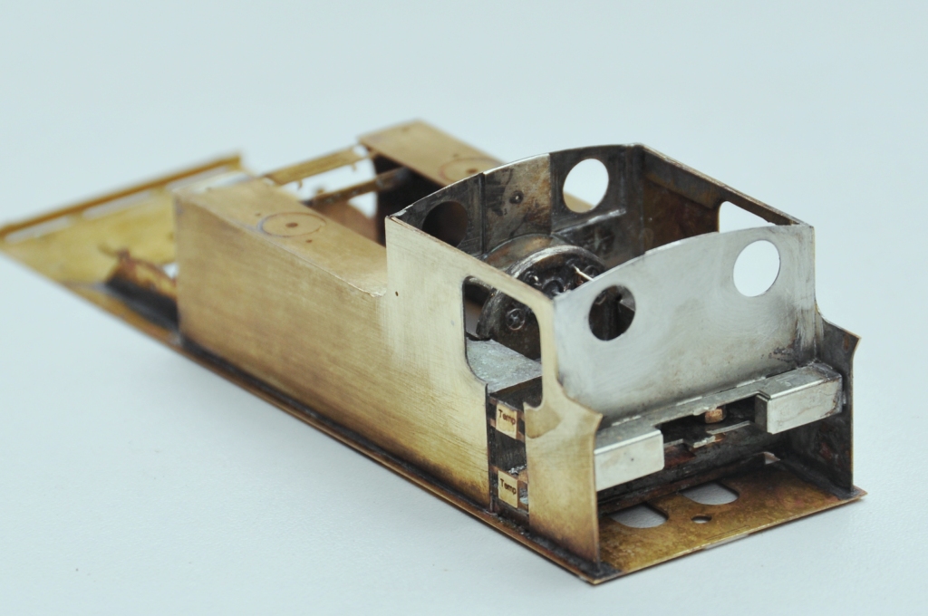
The cab fronts that were constructed earlier were no slid into place and I was pleased to find that it all fitted very snugly and in exactly the correct location. I did find that I could put in a further pair of fold up tabs on the running plate that meant that it was essentially impossible to put this in the wrong location, so this is another little refinement that will make its way into the production batch.
The rear of the cab was a similar fold up unit to that to the front, which was pretty easy to build but did have one dimensional error at its base that needed cutting away – well that is the purpose of a test build! All of this, has been created from one piece in maybe three minutes!
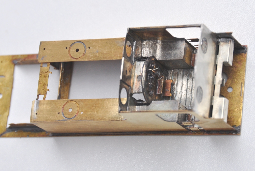
And this is what it looks like with the cab rear in place. If you look carefully, a couple of 12 BA screws are just visible in the cut out to the rear of the cab – the purpose of these will become apparent in a future posting but it is another one of my little ideas to make this easier to build/better when built.
And this is what the cab bow looks like from above, after the addition of the splasher tops and backs. One of the issues this illustrates is that this kit, as it stands, will only work for EM or P4 modellers. There is insufficient room to get the narrower gauge/wider wheel treads into the splashers.
Next up will be the cab roof………….
Test Etches and Prints
I have had the test etches back for some time and have had a play with them. This is what they look like back from the etchers:

I did find that I had made a number of the components to fine. I had prototype information, so I had made things like the balance levers to absolute scale and this is too delicate, certainly for 4mm. So they look beautiful in the etch but would not survive on a layout. Fortunately, I had also done an etch of the arms and signal components in 7mm, so I was able to do a little bit of 7mm modelling. This used a Lochgorm Models etched post and my design of base is where it gets too (sorry, slightly fuzzy picture):

I also got the first of the 3d prints back from Shapeways and these are very good indeed, so I am well chuffed with them! They are slightly difficult to photograph but here is what these look like:

I need to make a couple of tweeks to these and get a revised print done of them. I have a miniature etch for the handles done, then I will make a few resin copies of them and they are done!
I also had the finials and lamps printed; the lamps worked fine and so did the finials in 7mm but they proved far to fragile in 4mm – so again I need to make a few key elements overscale to be able to use it.
More 3 D Printing
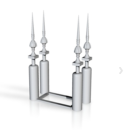
Whilst my orders for earlier work are underway, I have done a bit more drawing and have now drafted up some lamps for the signals; as below:
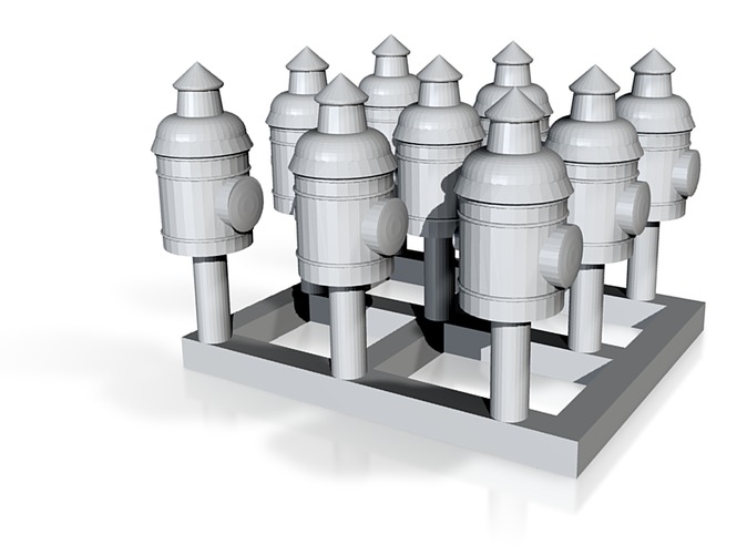
I have also managed to sort out a drawing that I did some time ago for a water column. The larger of the models for 3 D printing need to be hollowed out (to save on the printing medium, which is charged for by its volume). This took some time to get right, as I had multiple different parts I was working on.
So these have also be sent of to Shapeways for printing. As before, I will use the lamps as masters for lost wax casting (another new trick to learn!) but the water column will be used as a master for some resin casting (the old dog really is going for lots of new tricks) – it will also need an etch for its operating arm.
However, lets see how good they come back first – as I think I am probably counting chickens prematurely here……….
More on the etching and hopefully some 3-D printing
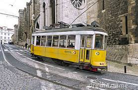
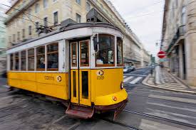
I received the test etch back from the etchers and after a family holiday (Lisbon – hot but great and with fab trams – see below………) I have had a chance to look at it.
I still have some things to learn, as where I have drawn things up at 4mm the smaller elements have come out a bit fine. so things like the framing around spectacle plates or the cross to the centre of the brackets is a bit too delicate to use. Also, I made a number of the fold lines and the holes are a bit too small so need to be drilled out. Thus, whilst the 4mm ones are usable, they can be done better so I am going to edit the etch.
I also included the signal arms etch at 7mm and this is much better. Whilst one or two elements would benefit from a slight redraft, it is definitely usable and therefore I am just in the process of some 7mm modelling (excommunication from the Scalefour Society?). I’ll get some posts up when I can get it a bit further.
In the meantime, I have also managed to have a bash at some 3-D modelling on CAD to get some finials made up. The idea will be to do an initial set via 3-D printing and then to use these to make some lost wax castings. Whilst these are available via MSE as a whitemetal casting, they are very delicate and will last very little time in my clumsy mits. I will do a lamp via the same route for the same reason.
Anyway, this is what the 3-D model looks like (actually the final version has a sprue coming of the top to support the top of the finial but it rather blocks out what it is you are looking at):
And to give a flavour of the trams in Lisbon:

Glenmutchkin Part 4 – Inspiration
Glenmutchkin’s main source of inspiration is Wick or its slightly more slimline cousin, Thurso. These are very similar in layout except for their MPD’s; where Wick’s was quite a lot larger.
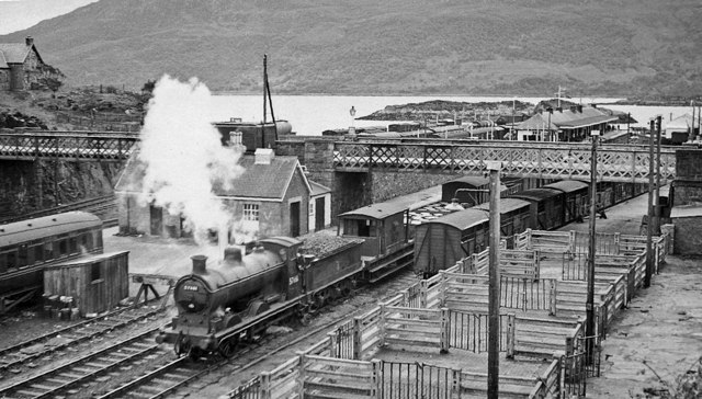
An overall view of Thurso in the 1970’s, with thank to Richard Oaks
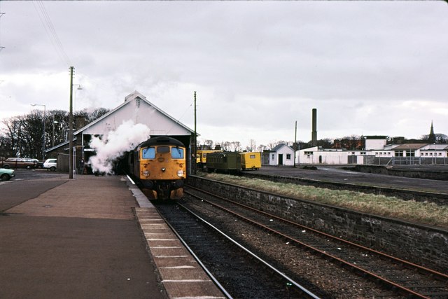
Wick in 1983; photograph by Peter Whatley with Creatives Commons Licence
However, rather than a facsimile of either (hey Ben Alder/Richard Oaks has nabbed that idea anyway!), I am proposing to use the same arrangement of MPD as at Kyle of Lochalsh’s shed area, with the access road leading to a turntable and then the shed roads coming back off this. Due to the way that the layout will sit in its home, I have had to do a mirror of the shed at Kyle but otherwise it will be the same.
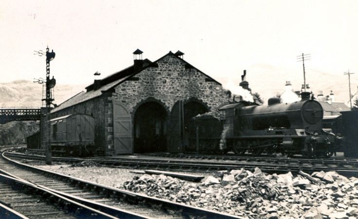
A rather fab photo of Kyle shed with a superheater goods (which were the mainstay of the line from about 1930 through to just after the war) on shed. It is also a fine view of the signal here – one that I wish to model. Photo with thanks to Jim Payne and available at www.throughtheireyes2.co.uk
All of the lines to the west coast of Scotland; both built by the Highland or any of its rival companies or projected come late in the 19th century – partly as a result of Prof Aytoun’s story that I have paraphrased in part 2. Wick and Thurso however were built rather before this and are stylistically rather different as a result. The main differences are the way that the platforms were arranged and the use of a stone built station building/train shed. However, having decided that the Glenmutchkin was much earlier than this, I felt that I could assume that the terminus was built before any of the other lines to the west coast were achieved and thus use the older style of station. In practise I have done so because I wish to model the overall roof – probably the building at Wick as its screen to the end of the train shed is very attractive.
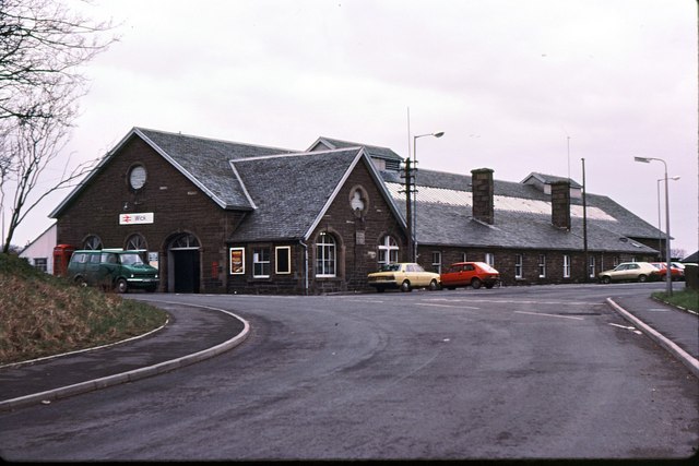
Photo of the road side of the main station building at Wick (that at Thurso is a bit smaller). Copyright held by Peter Whatley and reproduced under a Creative Commons Licence.
Another feature of Kyle that I will take is the overbridge splitting the station from the shed area. Being the son of a bridge engineer, I guess I need to get some proper civils into the model and the latticework is quite attractive. I will go for a single span bridge, rather than the twin span seen here at Kyle.
Copyright held by Ben Brookshank and reproduced under a Creative Commons Licence
Those cattle pens will appear at some point too!
Glenmutchkin: Part 3 – Era
Whilst I seem to be known in the electronic ether for my 1970’s modelling, this is not really my main interest.
Many years ago, I set my main era as the early years of the LMS. Whilst I do quite like some of the LMS standard classes, it was really the sight of the Edwardian and Victorian locomotives of the Highland in the lined red pulling a rake of fully lined coaches that seduced me. After all; who could resist something like this:
or this:
Its peculiar; I would think that the 1920’s is the least modelled era after about the 1880s? Think about it, when did you last see a model from this era?
My regret for this period though is the loss of the red oxide painted goods stock. The Highland often (apparently at random as to when they would and when not) pick out the ironwork of these in black and again I am drawn to the fusion of colour that occurred as a result. To get over this contradiction; I model in about 1925/1926. Much of the passenger stock and locos had by then been repainted in the new corporate LMS colours but at least some of the good stock remained in the old pregroup livery.
with thanks to Ray Nolton for two of the pictures
Glenmutchkin: Part 2 – What’s in a name?
Glenmutchkin may well be a new name to you but it is one of the forgotten names of railway history; railway proprietors and the public alike from the late 1840’s will certainly have known of it.
We need to take ourselves back to the mid 1840’s first; at the heart of the railway mania frenzy. Parliament was awash with schemes to build railways in every worthwhile corner of the country and a fair few worthless corners too – so much so that parliament had to sit through the summer recess to consider them (could you imagine that in the 21st century?). Already some farsighted commentators were predicting that a stock market bubble was forming and this provoked The Edinburgh Magazine to publish an article lampooning the mania – How we got up the Glenmutchkin Railway and how we got out of it; written by Professor W E Aytoun.
The story concerns Messers Augustus Dunshunner and Robert McCorkindale, two Glasgow rogues who conceived their scheme over a small barrel of whisky. They concocted a plan to relieve would be investors of their money by creating a railway scheme. First they found an area of the Highlands that other railway promoters had not yet spotted (that was simple, they just made one up) and proceeded to populate it with an improbable amount of commerce and agriculture. The human population was noted as being particularly dense, with the centre at the Clachan of Inverstarve. They concluded that 4 million cattle annually needed exported down the line, the hills were covered with sheep & goats but most importantly, the glen included the most of the famous distilleries in the country. Clearly a railway company to such an important part would attract the crème of Scottish aristocracy to its board and here our promotors surpassed themselves; the preliminary board included Tavish Mctavish of Invertavish, The Laird Mhic-Mhac-Vich, The Captain of McAlcohol and The Factor of Glentumblers amongst others. The engineer, a Walter Solder’s, initial report concluded that the fourteen mile line would be simple to build with four short tunnels being the only engineering features of note. Given that Mr Solder’s previous engineering experience lay in being a gas fitter, he can perhaps be forgiven in concluding that a total of 6 miles of tunnel through Scottish mountains would be “simple to build”.
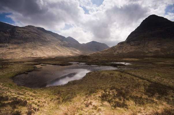
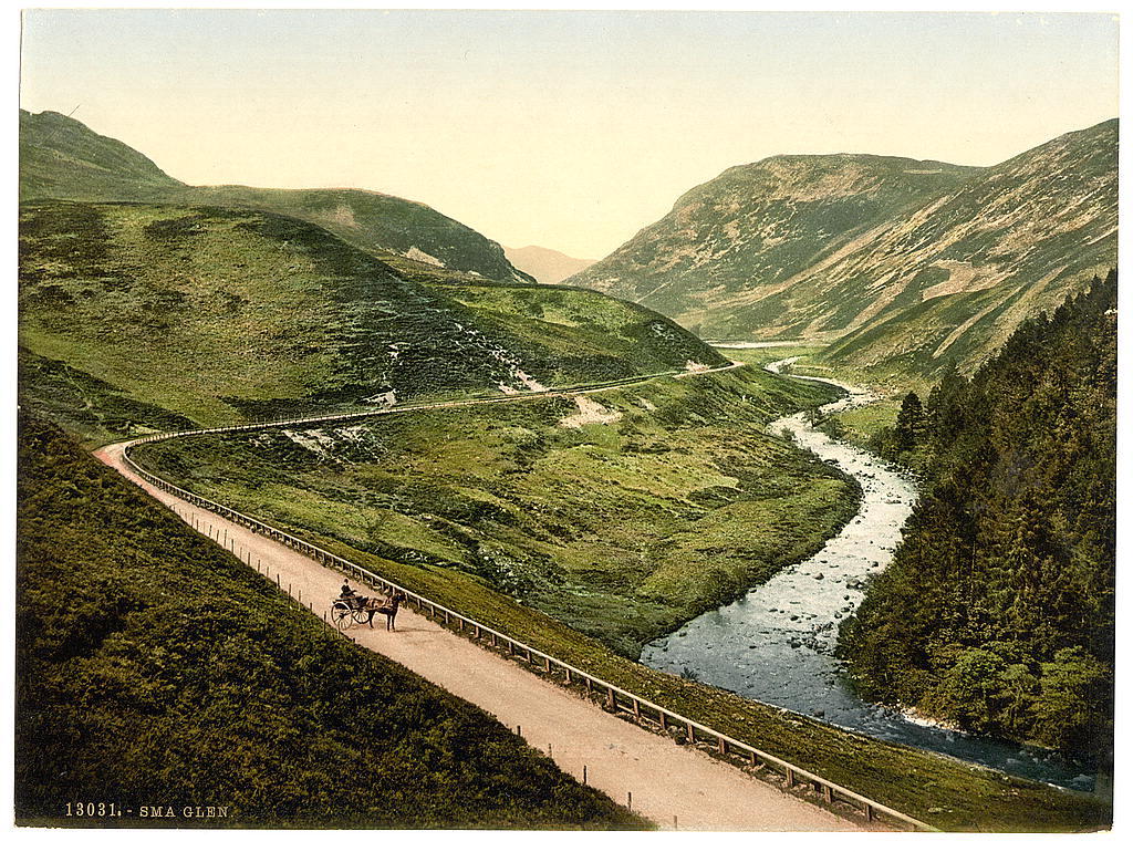
“Simple to build” – Glemutchkin today – photo via creative commons from Roger Maclachlan; although he might remember it as Rannoch Moor!
When Dunshunner and McCorkindale published their prospectus, they were not unduly surprised to find four other prospectuses in the same paper for schemes at least as outrageous as their own. Nor were they surprised to find that initial share issue to be several times oversubscribed; so they nobly sacrificed most of their holdings for hard cash. Armed with the initial subscriptions, our duo along with their company of advisors, friends and general hangers on headed to London to present their bill and oppose any that might seek to share the riches of Glenmutchkins. They fought “for three weeks the most desperate battle and might in the end have been victorious had not our last antagonist at the very close of his case pointed out no less than 73 fatal flaws in the plans presented by Solder”. Of course the opposition could have routed the Glenmutchkin line at the start, but they were just as anxious as anybody to enjoy the fleshpots of London at their shareholders expense. So all that was left for the promoters was to wind up the Glenmutchkins company and return the few pennies left of the initial subscriptions to the shareholders.
The article attracted wide attention at the time and planted the seeds for scepticism of the railway mania. Whilst the bubble will have burst anyway; the Glenmutchkin article certain pushed the crash along the way. This of course cost many people their fortunes but it also particularly hurt the highlands of Scotland. The article had been based on a scheme to open up a portion of the Highlands and even 20 years later, the promoters of railways in the Highlands found that the ghosts of Dunshunner and McCorkindale had not left the public’s consciousness.
Many of our layouts are based on “might have been schemes” – so I feel I am carry on the tradition, but with a slight twist to my “might have been”. And hey; there is all that cattle to be transported……………..
