Blog Archives
The Colour Red – or the Quest for LMS Crimson Lake
A topic that comes around from time to time, including to my lips, is what colour exactly is Crimson Lake? I thought that my analysis and that of others that have contributed to the discussions were worth sharing more widely; so here goes……….
The Historical Context
The first good insight I have is from George Dow who was a prolific author of the 1960s and 1970s, including on liveries who wrote in the Railway Modeller in 1973:
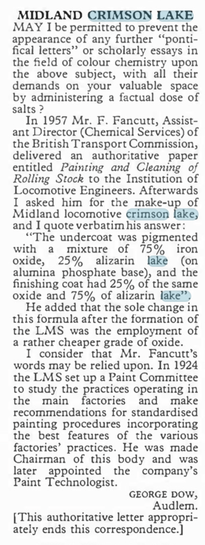
However authorative this is, fifty years later, with the change from natural to synthetic pigments this is not of great help. Also B&Q do not stock alizarin lake last time I looked as it is a pigment produced from a complicated processing of a vegetable and is probably fairly inconsistant anyway. https://www.winsornewton.com/row/articles/colours/spotlight-on-ruby-madder-alizarin/).
The Problem With Reds
Many years ago, when I was still in my shorts, I worked in a printing ink manufacturering business and red was one of our bugbears. This was for three reasons; as a colour it is less opaque than many colours so were prone to poor coverage, it is also prone to fading and like all paints, it is affected by the surface treatments, in our case varnishes. All of these issues affect how Crimson Lake appears on both the prototype and our models.
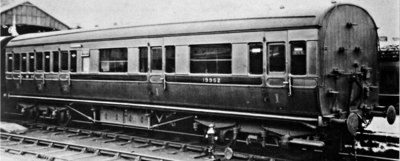
A Caledonian diagram 106 non-corridor composite shortly after being renumbered to 19952. This appears to have been acheived by painting over the predecessor number and then the application of the fresh number and then varnishing. The patches that have been so treated stare at you somewhat and ilustrate how the paint and lustre deteriorate! Photo by H.R. Norman ref 6081 and now in the NRM
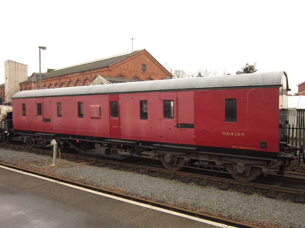
Its still a problem now too as this diagram 2171 full brake at Kidderminister shows. Photo SVR Enthusiast via Flickr
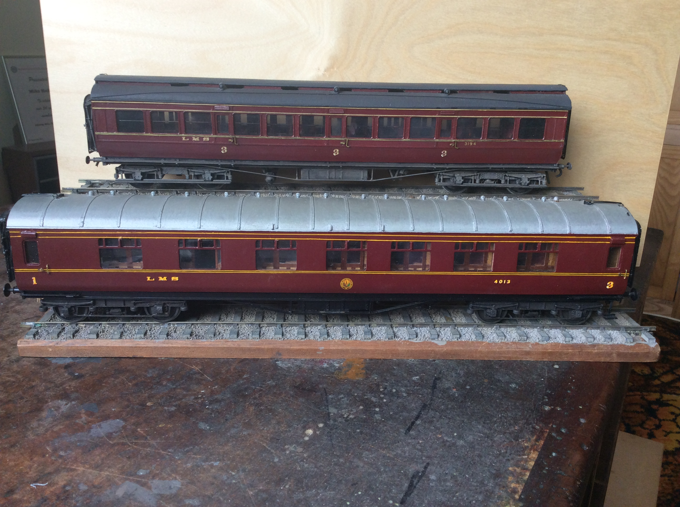
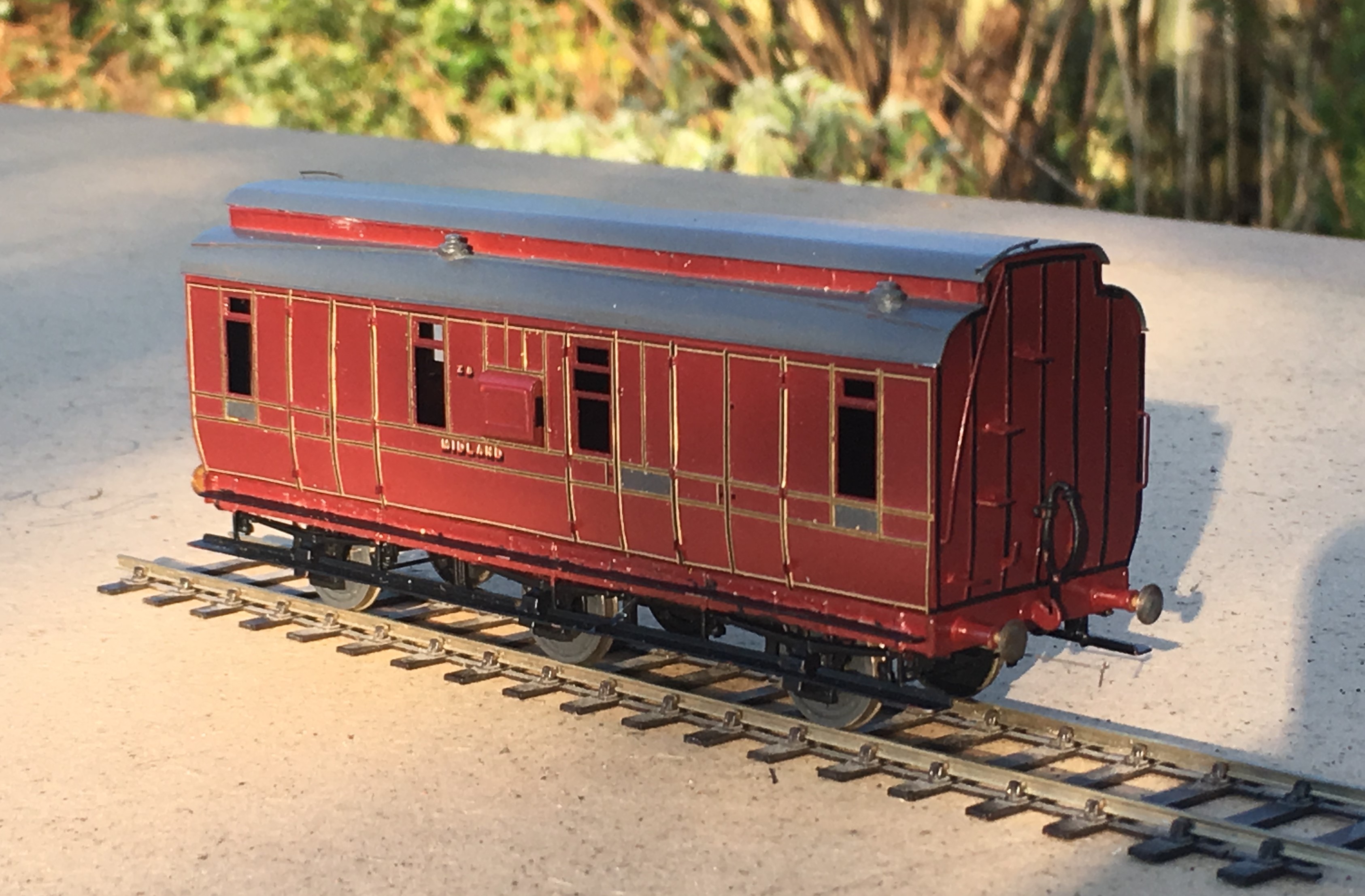
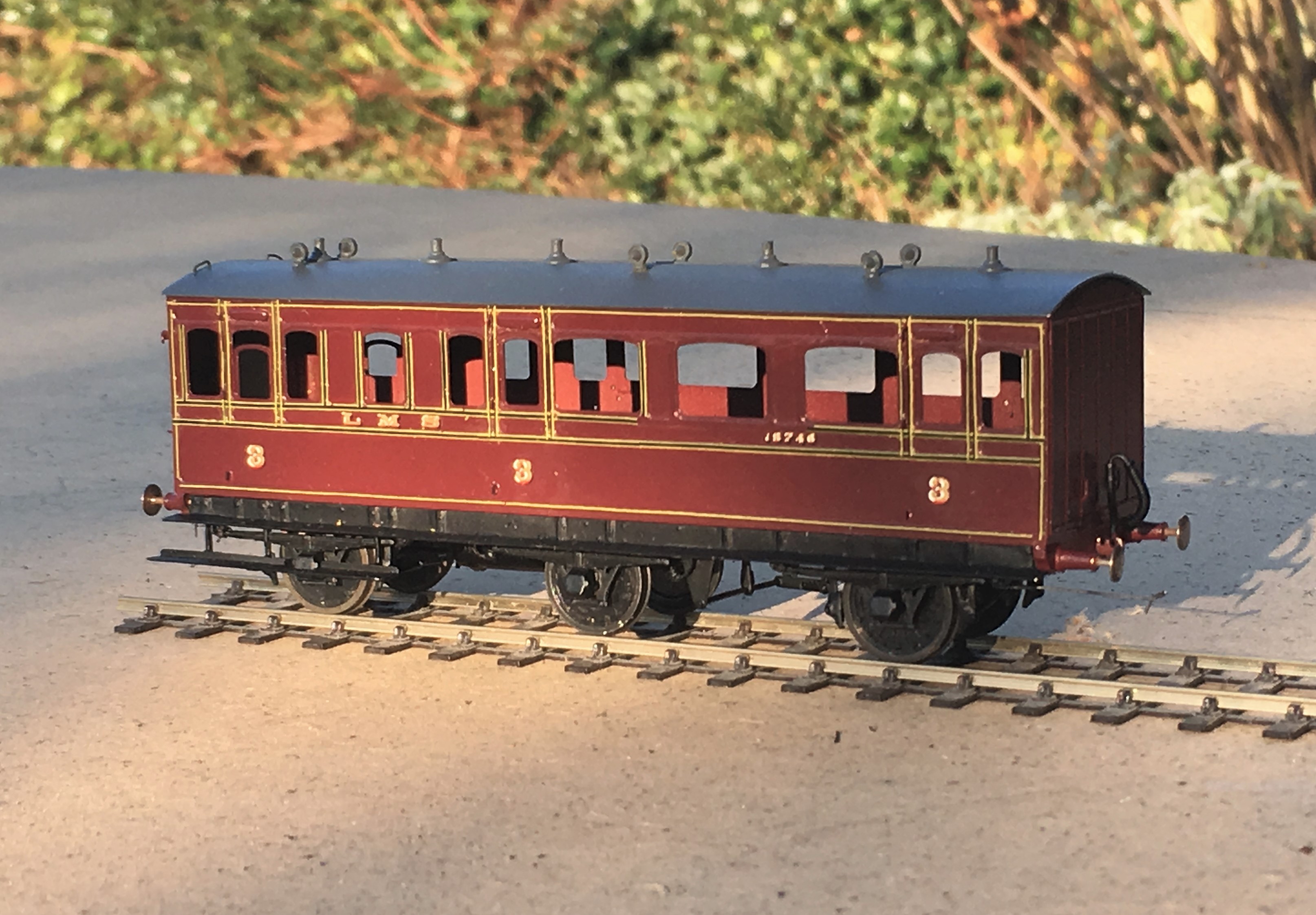
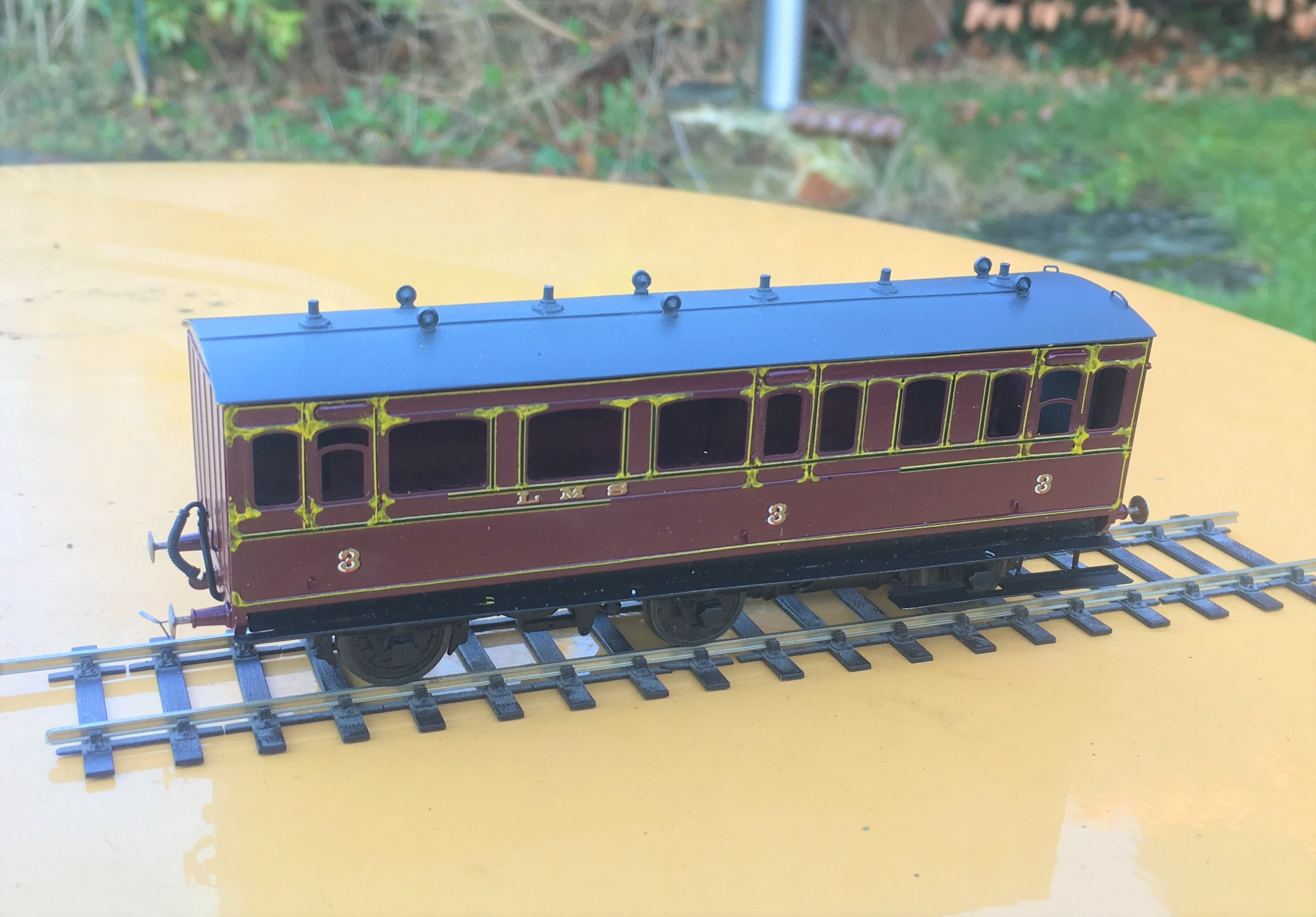
Both of these coaches have been painted in the same top coat, Precision Paints LMS Crimson Lake. The top coach, the clerstorey, followed the paint sequence noted by George Dow above – a first undercoat of LMS wagon grey, followed in turn by 75% grey, 25% crimson; 50% each; 25% grey, 75% crimson and finally 100% crimson. On the lower coach, the crimson was neat and painted over an undercoat of LNER bauxite. Both were painted at the same time, in otherwise the same manner and in both cases they were varnished but not weathered. The difference is startling! Photo and models by John Hastings Thompson.
Does Colour Scale
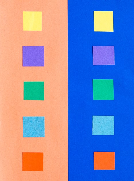
Like weight, I am not convinced that colour scales or perhaps it does but given that our models are smaller than the prototype it is more heavily heavily by contrast. I am sure we all know about the optical illusion causing the viewer to read differnt colours of the same sample by virtue of the background – is this happening to us as we perceive the colour of a model? Try the sampel from the Exploratoium below:
The presence of lining is also a major influence of the feel of the colour. The gold and black of the LMS seems to add a bit of sparkle and depth of colour to the red.
It was a Long Time Ago
We must also remember that the last LMS crimson lake locomotive or coach will have been repainted seventy years ago and even the last BR maroon loco was withdrawn sixty years ago (plus there is the argument as to whether they realy were the same colour as well!). Whose memory of colour is good enough to survive this long? Even photographs from this era as a whole cannot be relied upon due to the variability of colour rendition, the nature of the light that the subject was recorded in or the level of contrast with its surrounding – none of these issues have gone away with modern digital photographs!
I for one have never seen either original colour and my view of what crimson lake is being based on the preserved locomotives that I have seen over my life. Have the preservationist got it right? Maybe they are better informed than you or but if this was true, why is there so much variation in the colour from the ready to run manufacturers or even the paint manufactuers?
However, whether they are right or not, the preservation scene has set my expectation of what the right colour is and I suspect the same would be true for all of us. Whilst I hate making modelling decisions on any history which is not real, I have reached the conclusion that the right colour for me is one that matches what I have seen in the UK preservation scene.
Where does this leave us?
Possibly the first conclusion is that there are a wide variety of reds that we can safely consider to be correct for Crimson Lake – phew, because when I look at my models I do have variences!
The second conclusion is not only is some inconsistancy acceptable, it is actually essential because red faded so noticeably. I am less convinced that the changing of hues seen across some colours but a toning down of the colour and tinging to a more matt colour is definitely prototypical.
In my personal quest for a colour I have been through multiple agonies to get the right colour. Thirty years ago, it was Precision Paints Crimson Lake but this seemed (to me anyway) change and become too purple over time. I then used Rover Damesk Red from a rattle can but found this too uncontrolable or, if I held it further from the model prone to to giving the orange peel effect. I was then put on to the solution to all our colour problems by Jim Smellie (of Caley Coaches).
This suggestion was to use the colour that the preservation industry generally use to source paint for the 12 inch to the foot models. This comes from Craftsmaster paint who have a series of specialist railway colours for most of the colours that we will wish to use. I use a numberof their colours including Crimson Lake. I have yet to adulterate this but i do intend to let it down with some white to imitate fading – hopefully this will not send me down another quest for the right faded Crimson Lake!
Scaleforum at a Screen Near You Soon!
With these strange times that we have been experiencing for the last six months, we have all become a bit cooped up in our abodes. Whilst the lack of model railway exhibitions is hardly going to make the six o’clock news (can you imagine!), I for one have missed both the inspiration and the camaraderie they offer.
We have not seen a plethora of on line exhibitions so it is welcome news to see the Scalefour Society making the effort to arrange one in place of their annual exhibition. This will “take place” on Saturday 26th September between 10:30 – 5:30 although it seems much of the content will be available thereafter online. Here is a trailer for it:
In addition to seeing familiar faces again, I was particularly struck by the possibility of seeing a number of “home layouts” that we don’t ordinarily get to see – and some big ones at that!
Some seems to be by video and others by an interactive youtube link so that you can chat to the team/person. This is the listing of what is proposed.
Layouts:
Boston Frodsham by Mike Knowles
Bristol Barrow Road by Robin Whittle
Central Cheshire Lines by John Sherratt
De Graafstroom (P87) by Vincent de Bode
Drighlington and Adwalton by Steve Hall
Eridge by the Kent Area Group
Faringdon by Rex Davidson and Stephen Williams
North Elmham by the North Norfolk Area Group
Obbekaer (P87) by Geraint Hughes
Pwllheli by Jonathan Buckie
Southwark Bridge by Mike Day
United Mills by Ray Nolton
Demonstrations
Adrian Musgrave – Signals
Alistair Ford – Timber Buildings on Black Gill
Brian Hingston – Coaches
Chris McCarthy – Baseboards
Dave Keeler – Wagon Construction
David Brandreth – Resistance Soldering
Jim Smith Wright – Soldering White Metal
John Farmer – Scenics
Mick Moignard – DCC Sound
Nick Rogers – Wagons
Rod Cameron – Lewis Project
Stuart Holt – Tree making
Illustrated Talks
Martin Nield – Authentic Model Railway Operation
Jim Summers – ‘Earning a Living’
I can see that chunks of the readership of this blog are dispersed in far flung places – take some time to see some really good 4mm without burning your air miles. The details to the log in can be found here:
So I know what I will be doing with much of the 26 September…………………. I will even make sure I have done some on-line shopping at about the same time so that Scaleforum hits my pocket in the same manner as usual!!
Only the printable words for this Wednesday!
Hmmmm……..
A signal imitating a Fresian cow was not the effect I was after…………..
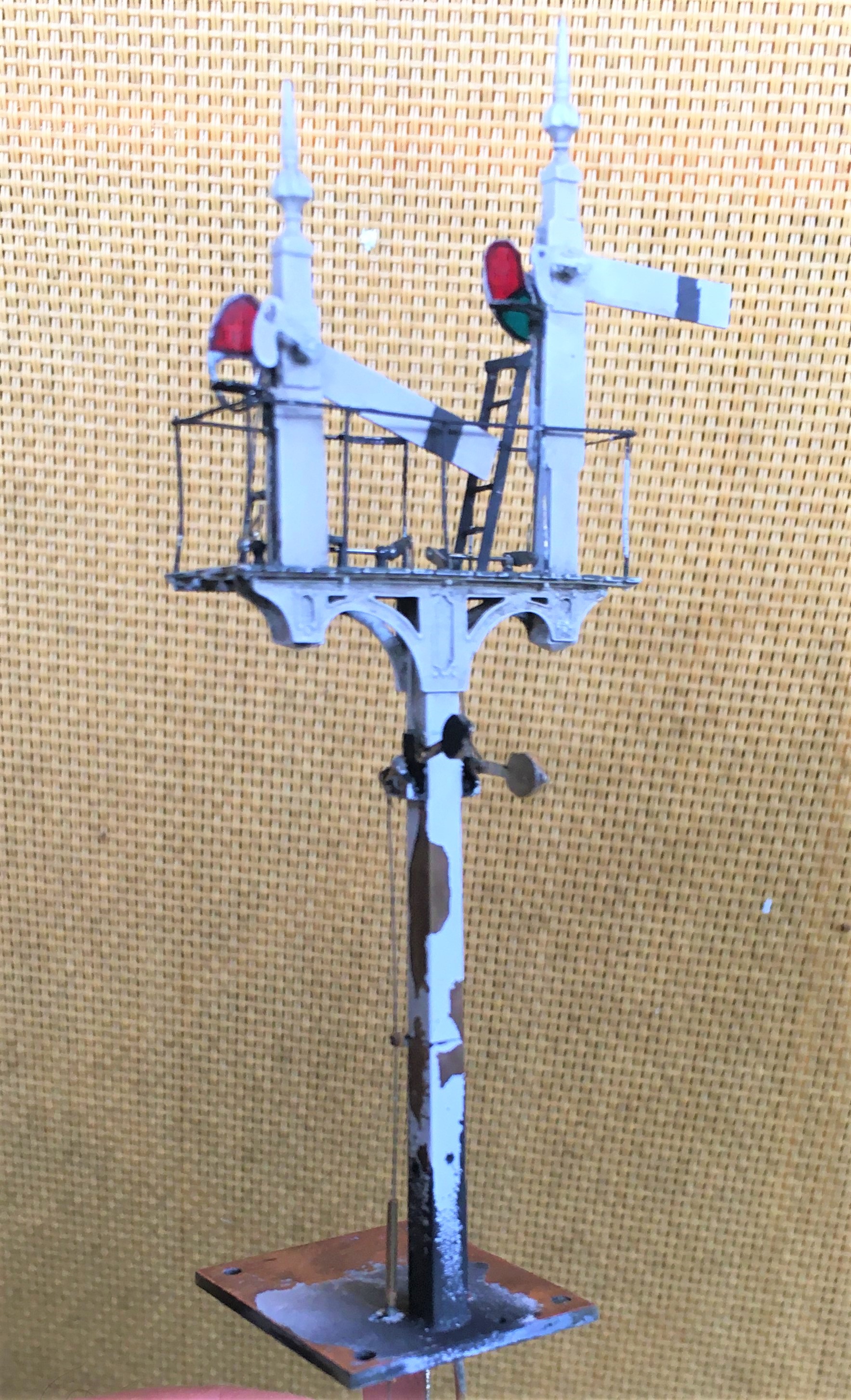
Halfords etch primer is obviously not that etchy!…………….. So someone will be waiting a tad longer for their signal than I thought…………
Tatty’s Top Tips – Signals
A mere three weeks ago, but a lifetime in the past now that we are in the middle (or more worryingly, perhaps just the beginning) of the Covid-19 crisis, I was a demonstrator at the joint EMGS/Scalefour Society skills day. These skills days are not really exhibitions and are instead aimed at passing some skills on to the visitors – thus they are primarily a hall full of demonstrators with only the odd layout or two to break up the rows of desks.
Here I am, in a shockingly creased shirt (!), and as you can see, I am demonstrating signal construction. I am pleased to say that at the skills day I had a solid stream of people engaging with the topic all day; so much show I had to pull down the shutters for a brief lunch as otherwise I really would not have stopped all day!
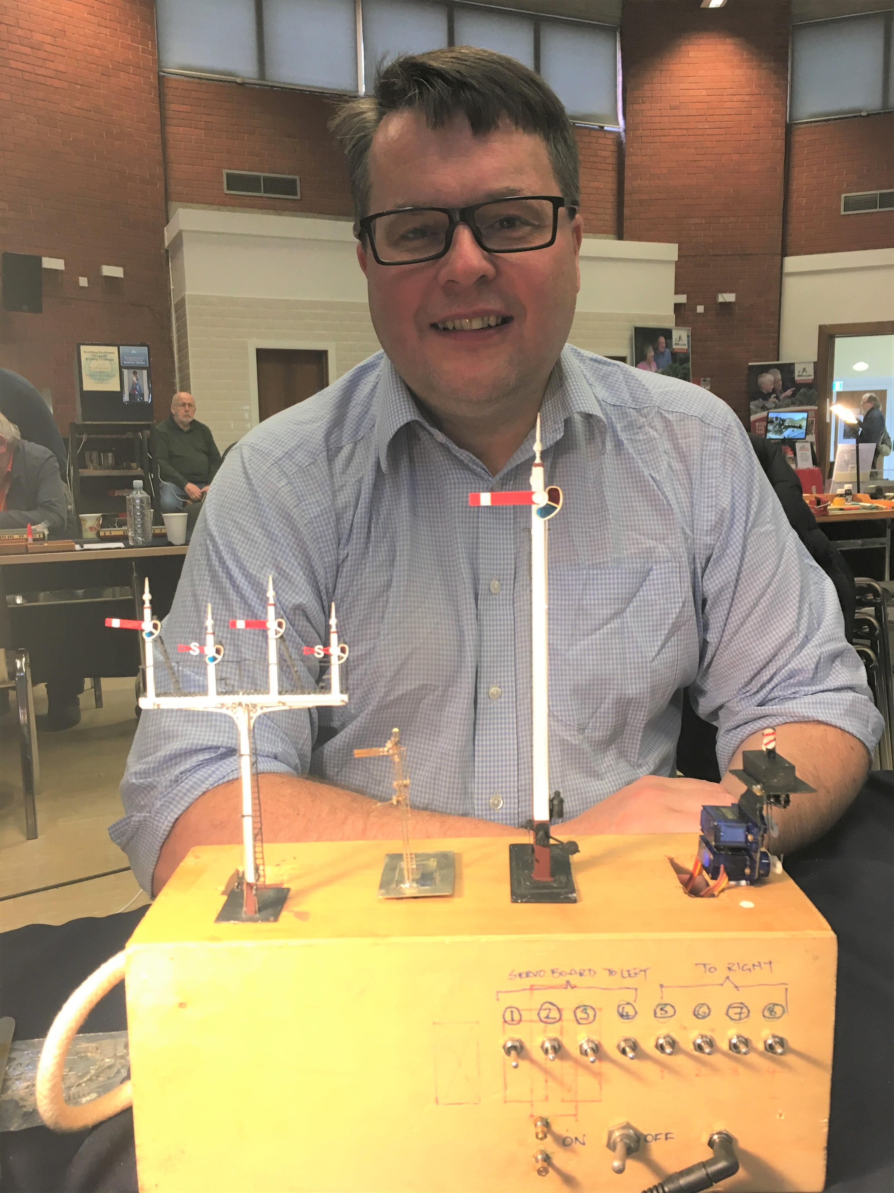
By way of preparation for the event, I thought about what I have learnt about building signals and distilled a list of my top tips. These proved to be the cornerstone of my conversations with people at the Skills Day so I thought it was worth repeating them here on the blog.
Planning Ahead
- Conceive how you are going to mount the signal; where and how, what is above the ground or below the baseboard – which might well mean you also need to;

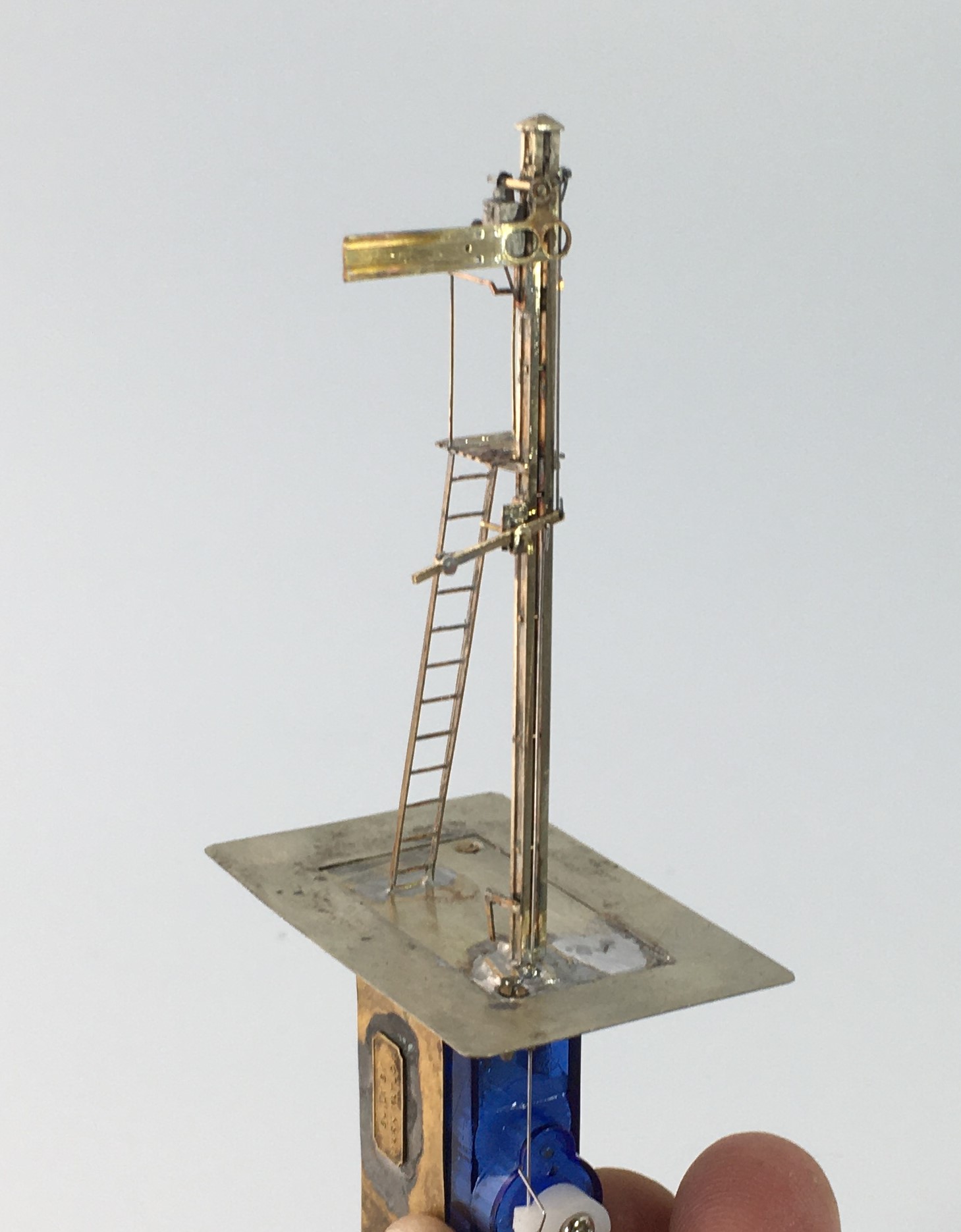
The base and mount for a two movement servo controlled signal
- Decide how you are going to operate the signal, how is the drive mechanism to be mounted and what does it need to be connected to mechanically/electrically;
- If you are going to illuminate your lamps, you need to decide how you are going to run the wires to the LEDs or fibre optic cable. It is possible to use the post as a common return but you still need one wireway;
- Consider how the movement is to be transmitted (especially bracket signals) and how you are going to replicate this? Multiple movements in close proximity to each other can lead to interference, compromises to reduce this risk are sometimes desirable (especially for triple or more movements in close proximity);
- Conceive how you are going to paint and assemble the signal before you start – it is generally easier to paint arms and ladders before you assemble them so it is possible to create sub-assemblies to be attached later – the touching in of local areas of damaged paint caused through assembly is a small price to pay for the ease of painting the remaining areas;
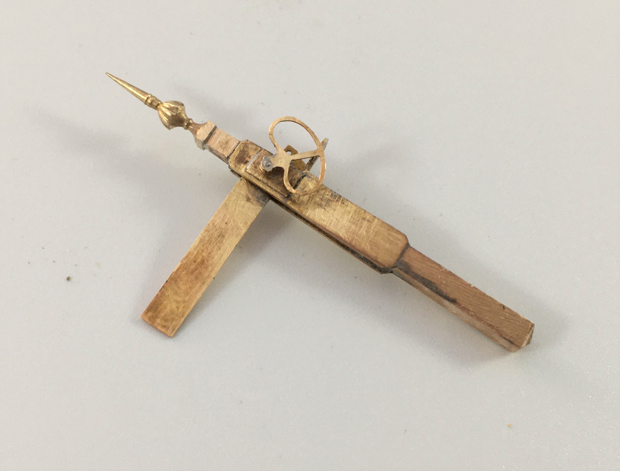
A Southern rail built home signal; the post was formed of two pieces of nickle silver rail.
Construction
- Tight, tight, tight – the most important part of building a signal is to keep all holes of operating parts as tight and snug as possible as slack leads to sloppy movement;
- You will use a lot of fine drills, down to 0.3mm, and a good quality pillar drill will mean you break rather fewer of them!
- Use the file up the length of the post not across it as much as possible – the files leave less scars and any that do occur mimic the grain of the wood;
- Pre-form or pre-drill elements such as balance weights, holes to the posts or landings early on before they are assembled when it is easiest (well potentially!);
- The prototype of most of the components to a signal are pretty delicate with fine sections; thus, to capture their character these needs to be similarly fine, however:
- There is a trade-off to make with the operating components such as balance levers which are typically best made over scale and with laminated brass to give them more strength;
- Generally, build the bigger more robust elements first and potentially alter the build sequence in the light of thermal mass and whether adjacent items might be disturbed by later additions – consider using different temperature solders and prefabrication of elements such as dolls with all of the lamps/landings finished;
A prefabricated doll and arm – I wouldn’t normally fit the arm until after painting but this is not true for slotted post signals
- Don’t use the flat etched ladders, they are too flexible to look real. Either use the built up versions or solder 0.3mm wire on both front and back of stringers and file the outside face flat – they look more realistic and are more durable.

A flat etched ladder with 0.3mm wire being soldered to the stringer
- Lots of delicate parts and complicated sections means that ultrasonic baths are really helpful for cleaning without damaging elements;
Slotted Post Signals
- Not the easiest because of the need to solder the arm to the spindle inside the slot. Use a laminated piece to the ear that is the point at which the operating rod attaches to the arm and extend it cross the back of the arm by 3mm so that it is would project beyond the slot slightly. Be liberal with the solder but make sure that the rubbing faces are cleared of any excess. Wrap the arm in cigarette paper and insert it into the slot. After the spindle has been inserted, touch the cigarette paper with light oil and allow it to soak through. Then put a little flux on the laminated ear and apply the iron. The heat will transmit along the solder joint and reach the spindle.
Operation
- Protect the signal from excess throw; they are delicate – therefore set the servo up to an approximate centre point through before connecting it to the model;
- Leave room to be able to see the signal as you are setting it up, otherwise it takes ages and a lot of bending under the baseboard;
- If you are going to illuminate your signal, understand what the right colours would be – oil lamps are relatively dim (so you need to resist down the voltage) and quite yellow (so modern LEDs need to toned down).
Dimensions
Dimensions were not standardised even within a company, let alone between, so offering directions on dimensions is dangerous – all I will say is these dimensions are commonplace:
- Single post wooden signals – 6” square at the top and then tapering out 3/16th of an inch for each foot of height (1.5% or so)
- Wooden doll posts – 7” square at top and tapering as before
- Main post for wooden bracket signals – 10” at the top and then tapering as before
- Single post tubular signals – 5 1/2″ to the upper portion and 6 1/2″ to the lower portion. The height of the lower portion varied with the height of the post (for details, see LMS journal no 4)
- Arm – centre pivot – 1′ 6″ from the top of the post; second arms 6′ 0″ below that;
- Spacing between dolls – 6′ 0″ or 6′ 6″ (less for shunt arms)
- Height of handrail to landings – 3′ 0″
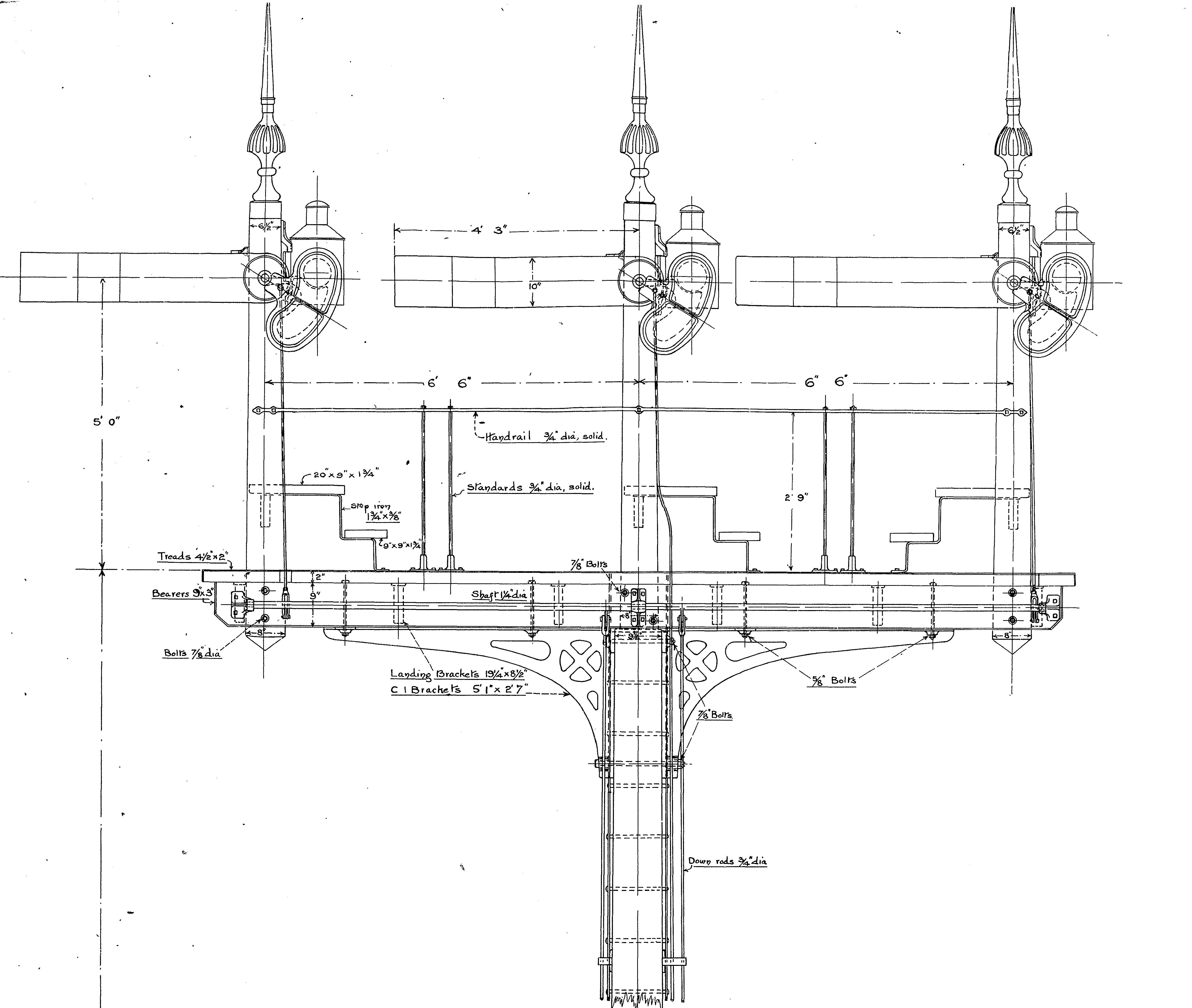
A GER three doll bracket signal
……part 2")
Let there be water (and coal too)……part 2
One of my pet hates on model railways are buildings that float a fraction above the ground because they have been plonked in situ, not bedded in. For me, it completely destroys the illusion and I can get quite wound up about it when I see it (…..and it is pretty common, so this is fairly often!).
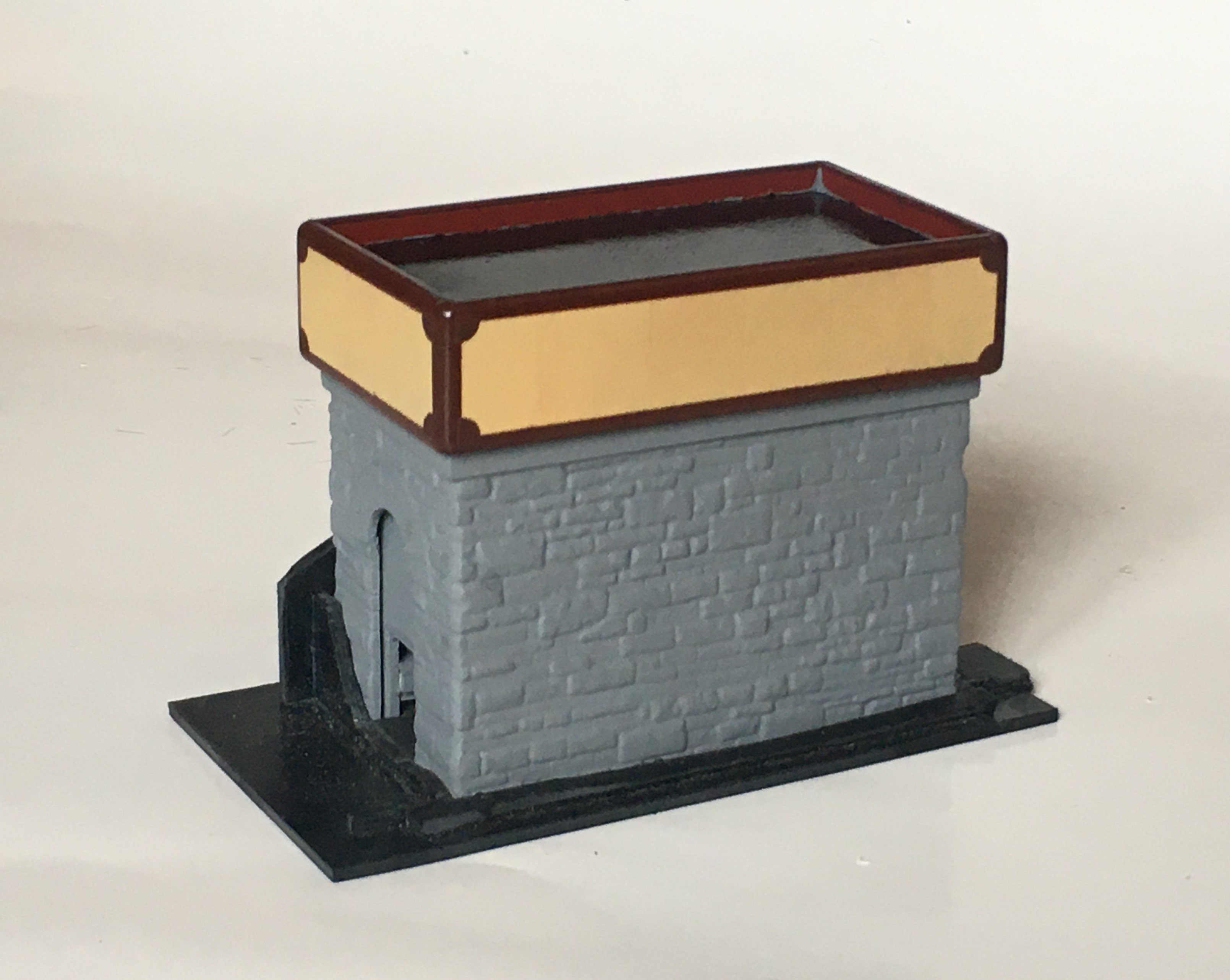
Occasionally, I actually do attach the building to the baseboard and “scenic in” the ground around them but more normally I construct a base into which the building sits. This gets embedded permanently and then the building sits into a slot that is formed into it. I have also seen the building being built in two parts, with the base being affixed to the ground and the building slotted onto them. Peter Bond did this for me with the signal cabins for Portchullin. This is the base for the larger water tank:
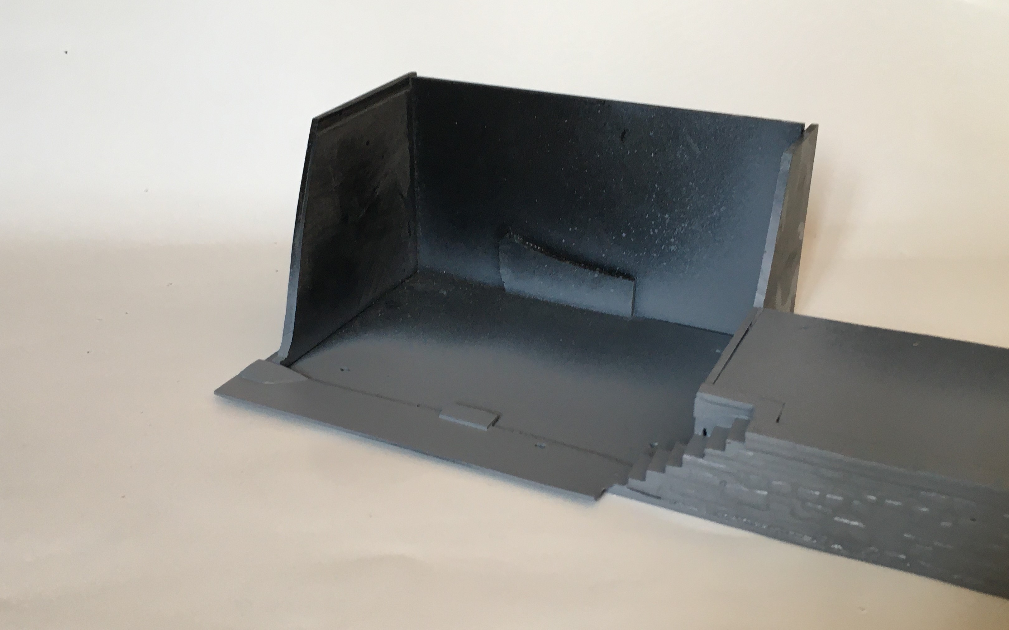
The large water tank is more prominent as it is located closer to the baseboard edge and is to the rear of the main focus of the MPD area, the trackwork between the shed and the turntable. It is also adjacent to the coaling bank and as a result I decided to make this now and as part of the base for the water tank.
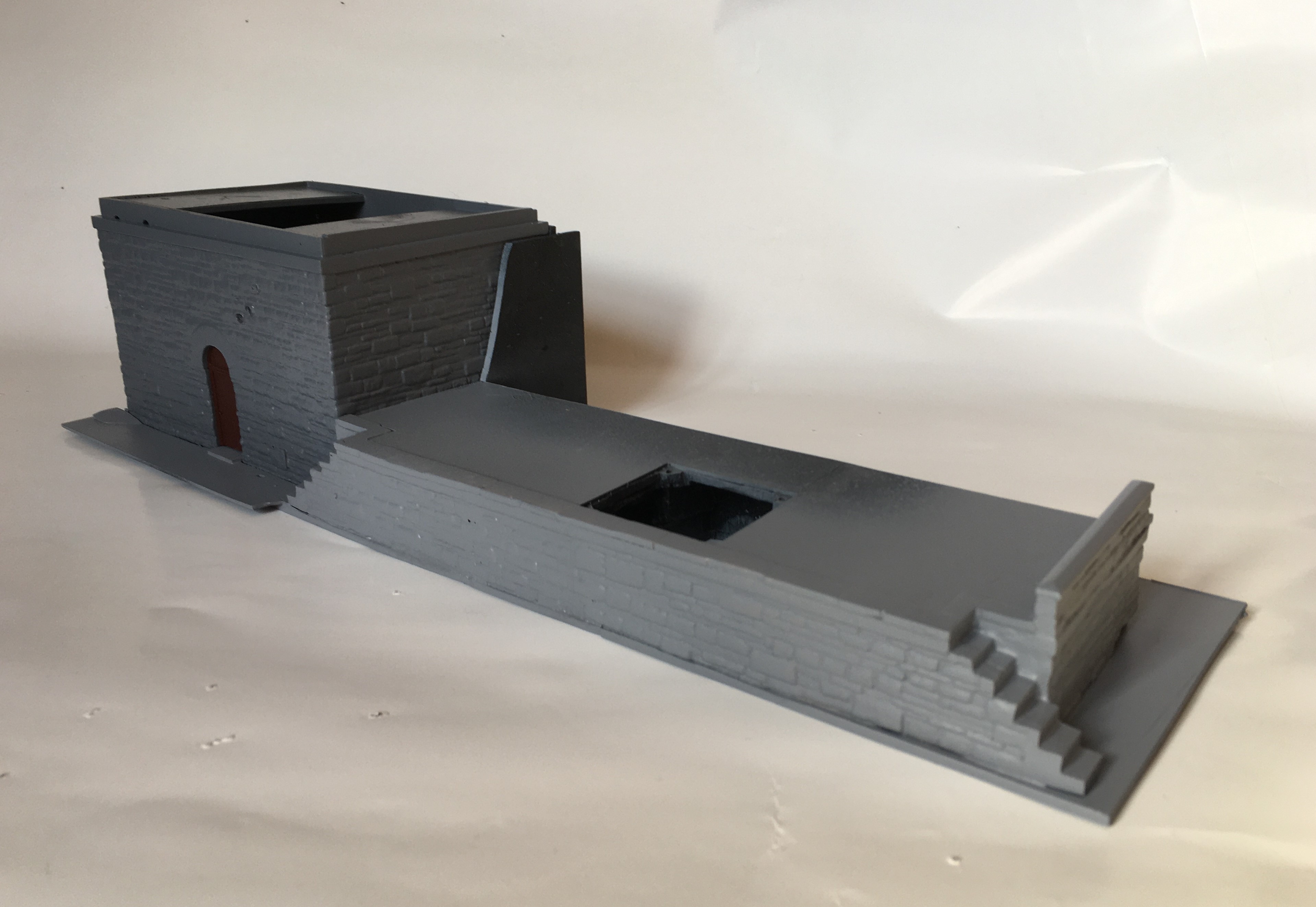
The smaller of the water tanks is designed to mask a baseboard joint in a rockface/embankment. The base (below) will thus be split into two halves when it is fitted, each sitting on adjacent boards – a neat way of not having the San Andreas fault line running through a rock face!
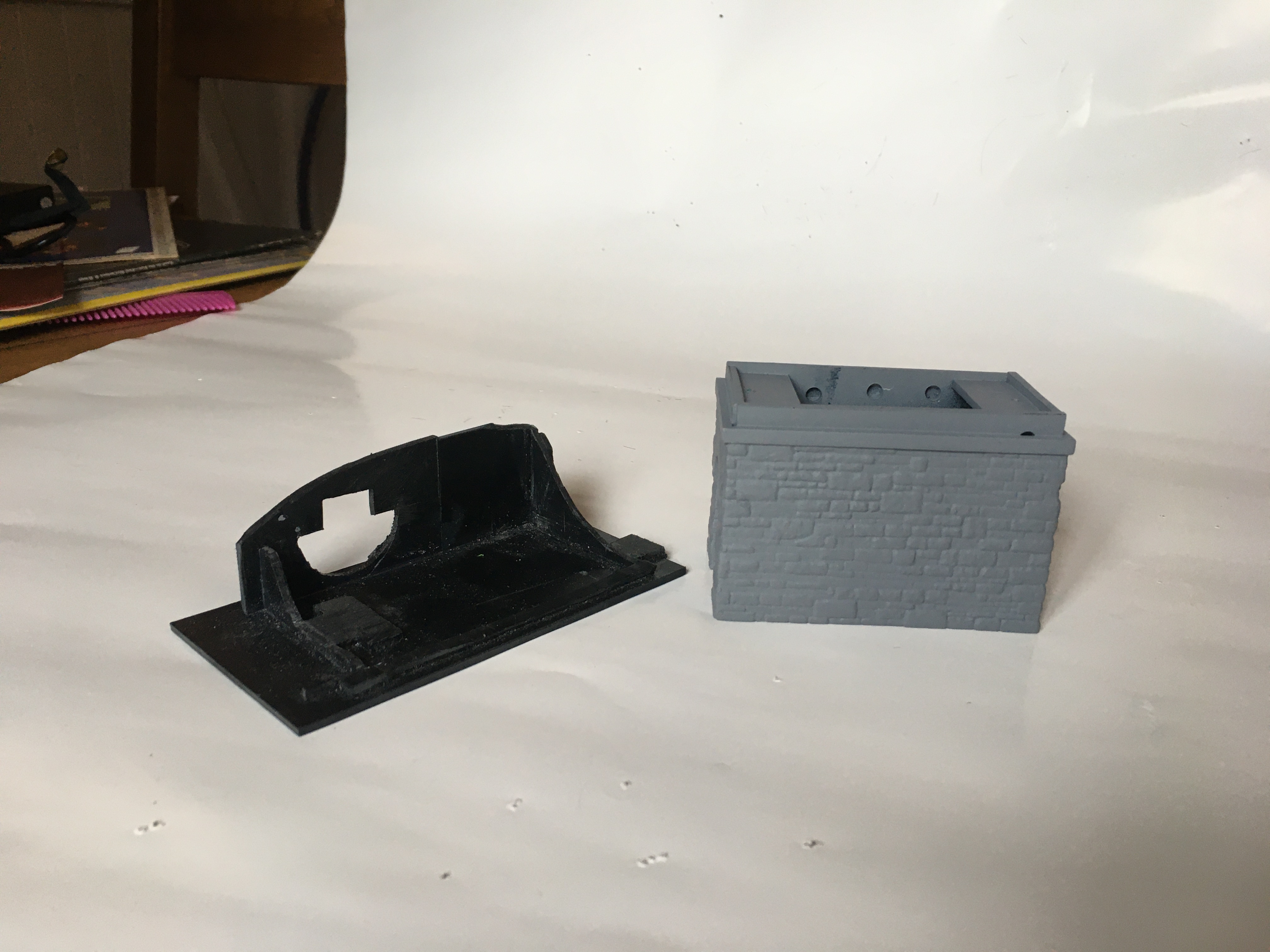
I have also started the painting of these, which had a fairly characteristic design with the border in a red/brown and a cream central panel. It is important to recreate this and as it is fairly eye catching, errors will be instantly visible.
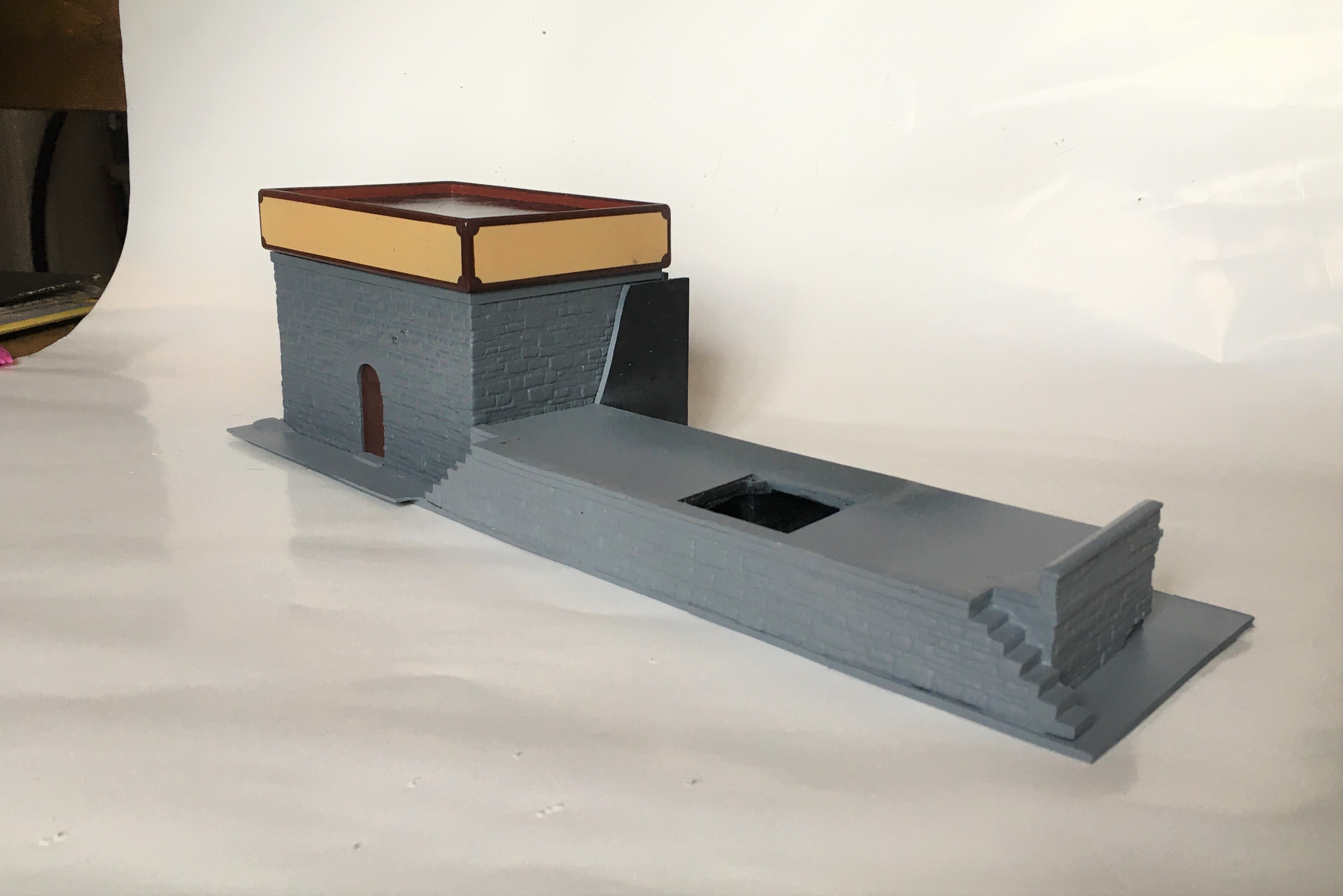
The straight edges weren’t too difficult to achieve with masking tape; initially the horizontals and then the verticals a day later. Peeling back the masking tape was a thrill to see if it worked!
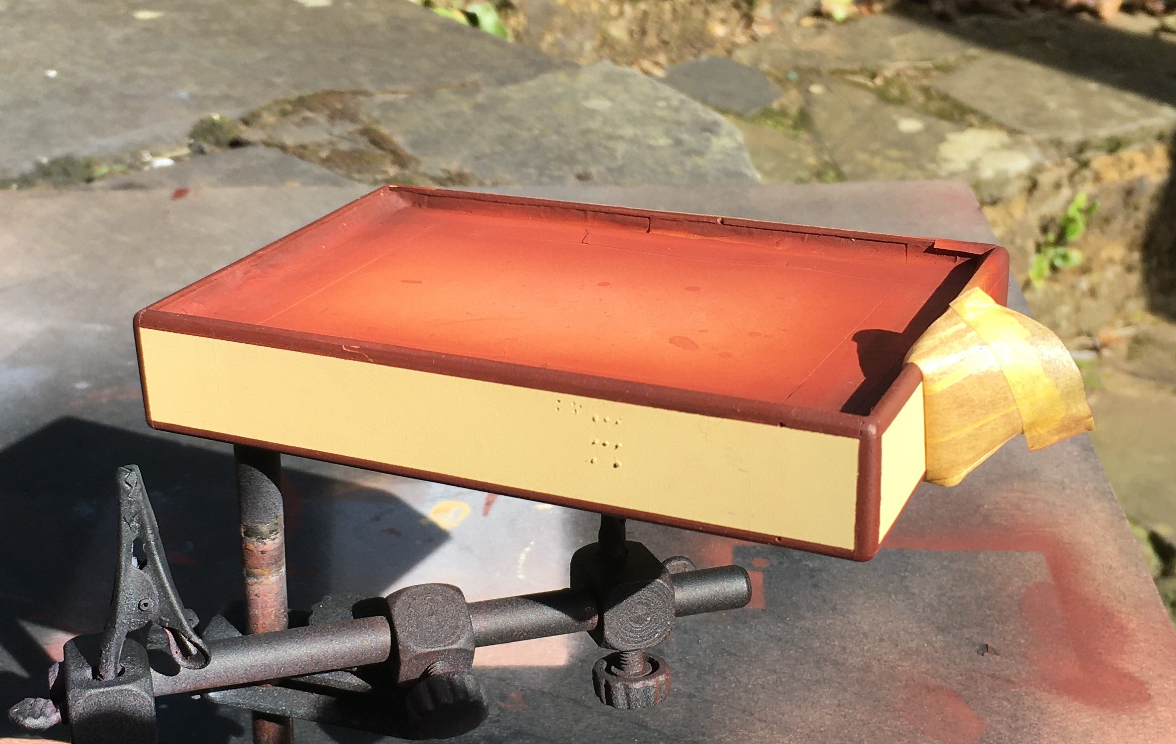
The scrolls at the corner was a concern throughout the construction of the water tanks but I did hit on an idea I think is rather nifty. I sprayed the same red/brown on some transfer paper (thanks Chris!) and once it was dry, used a domestic hole punch to create disks of transfer. I then cut them into segments that were a bit bigger than a quarter of the disk. They were then applied as a transfer to each corner.
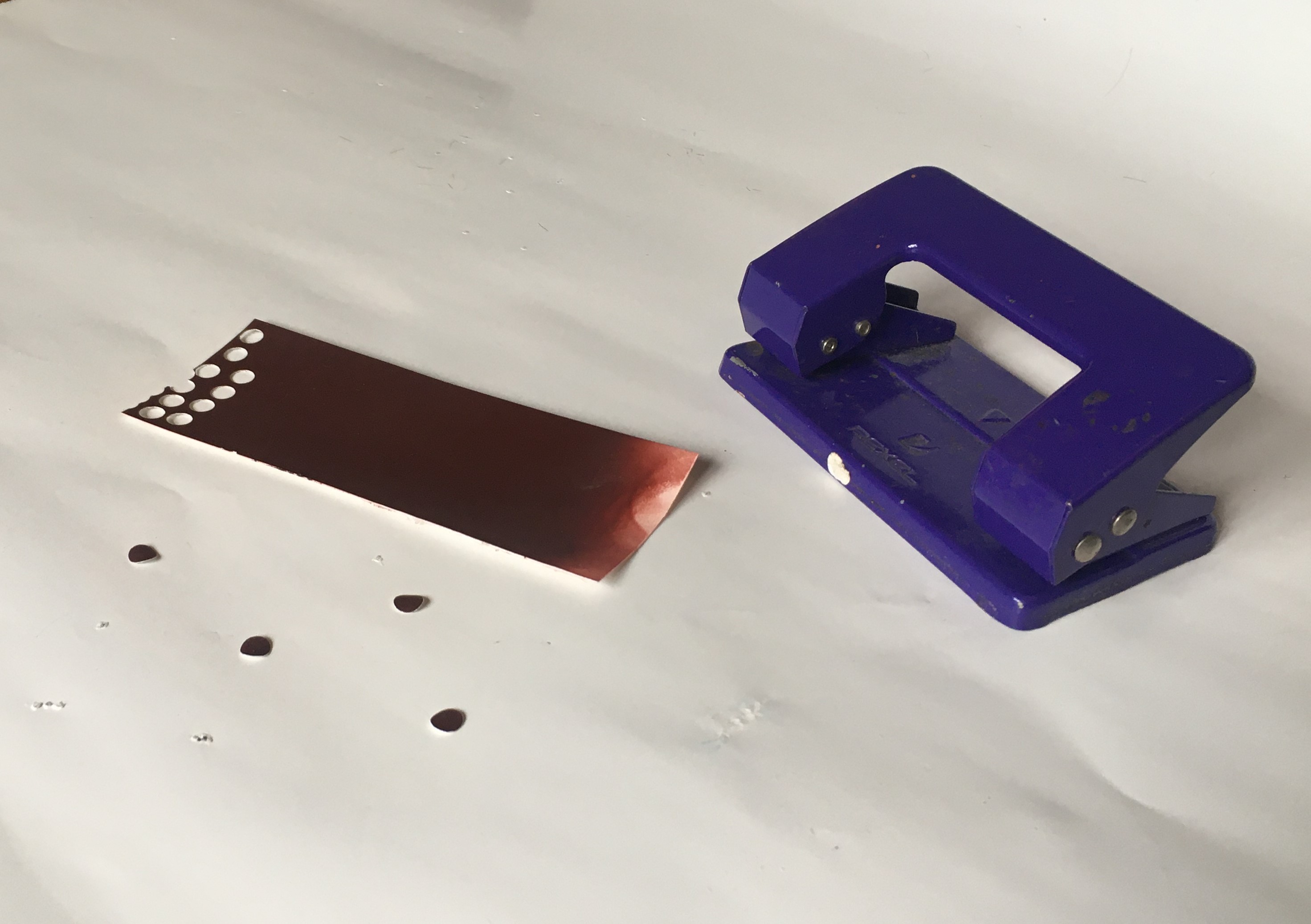
Actually, it was pretty easy once I got going – I definitely spent longer thinking about it than I did doing it! I am pretty pleased with the outcome, much neater than my hand could manage!
The rather prominent hole in the coal bank will be the subject of a future post, as there is something a bit different planned for this!

Lining Things Up….
As usual, I set off over the festive break with plans to do all sorts of things and failed to do any of them fully. One aspect that I did get moved forward though was the painting and lining of a couple of my six wheeled coaches.
Back in my youth, lining pens held no fear and I could genuinely dash off a fully lined coach in a few evenings. Thirty years of pushing a computer keyboard has dulled my drawing skills to the point where I am close to terrified to pick up a bow pen and I have not had the nerve to line a coach for a long time. I am confronting this fear in a couple of months by attending a class run by Ian Rathbone on painting and lining at Missenden Railway Modellers. In the meantime, however, I can still line utilising transfers, in this case those provided by Fox Transfers.
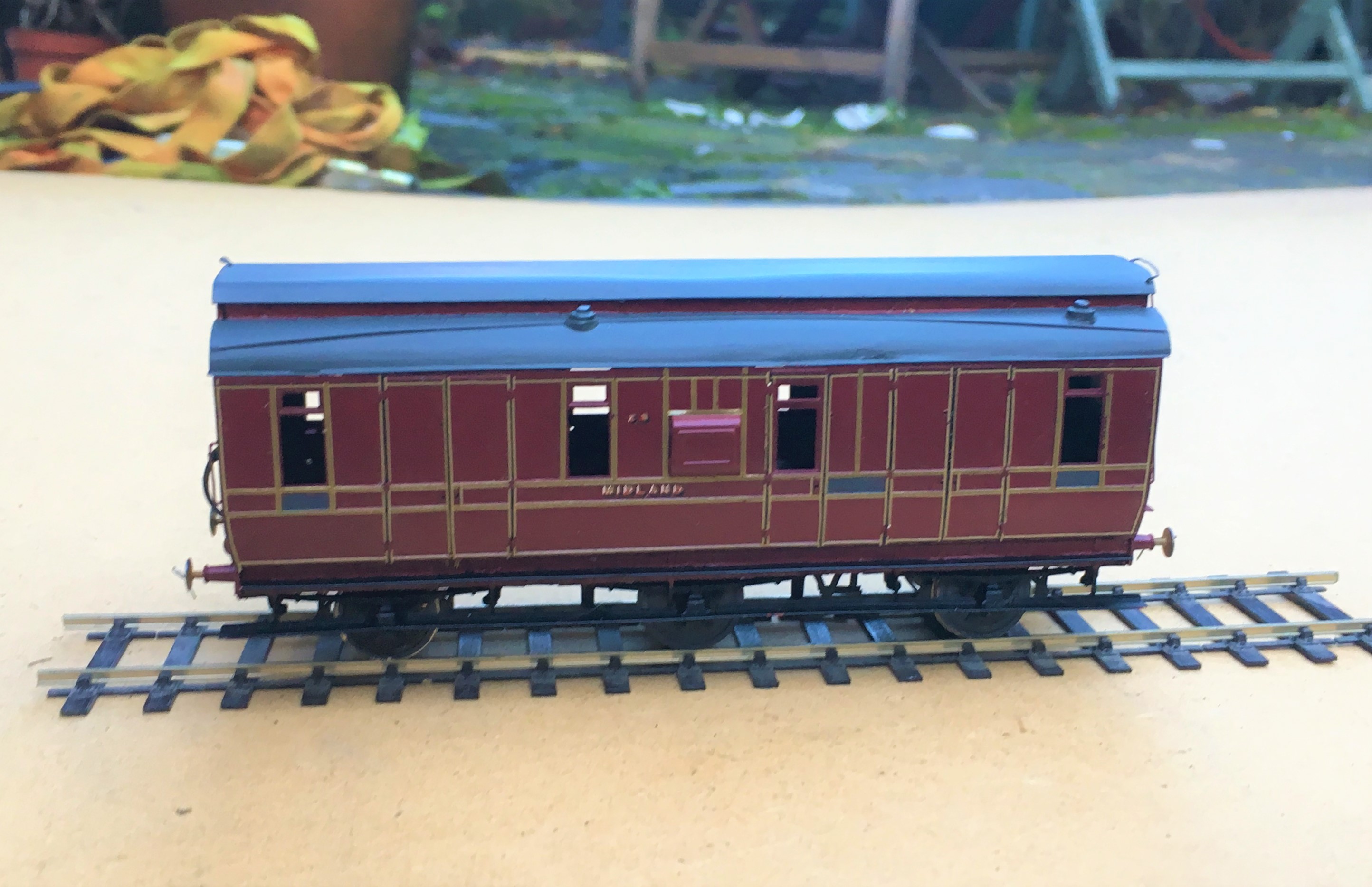
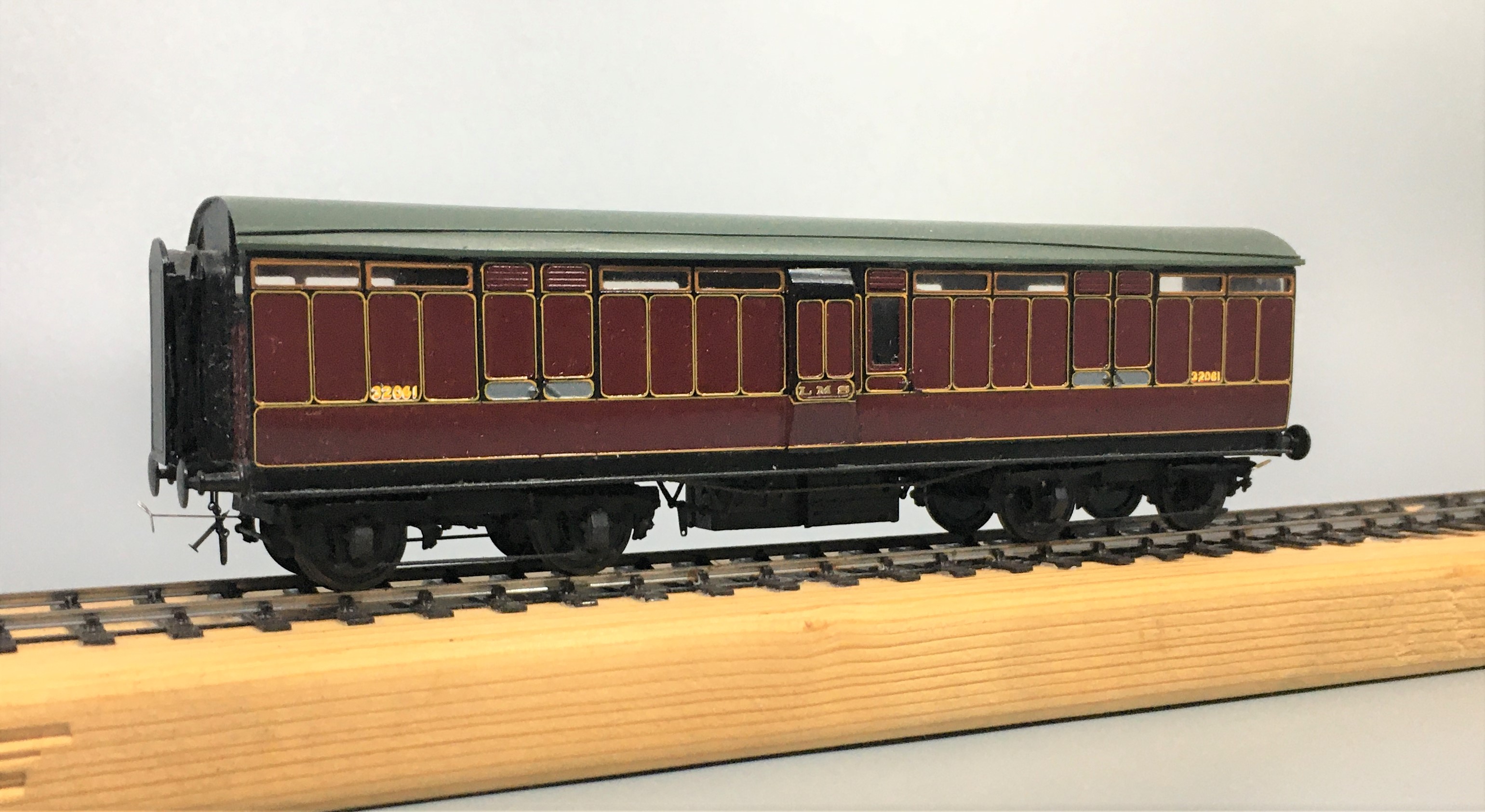
Being preformed in straight lines, these do work best for the square panelled beading of some of the Midland Clayton stock, like my dia 501 full brake. I had taken care in designing this with beading sizes that were correct (and matched the Fox Transfers). They thus work quite well I think.
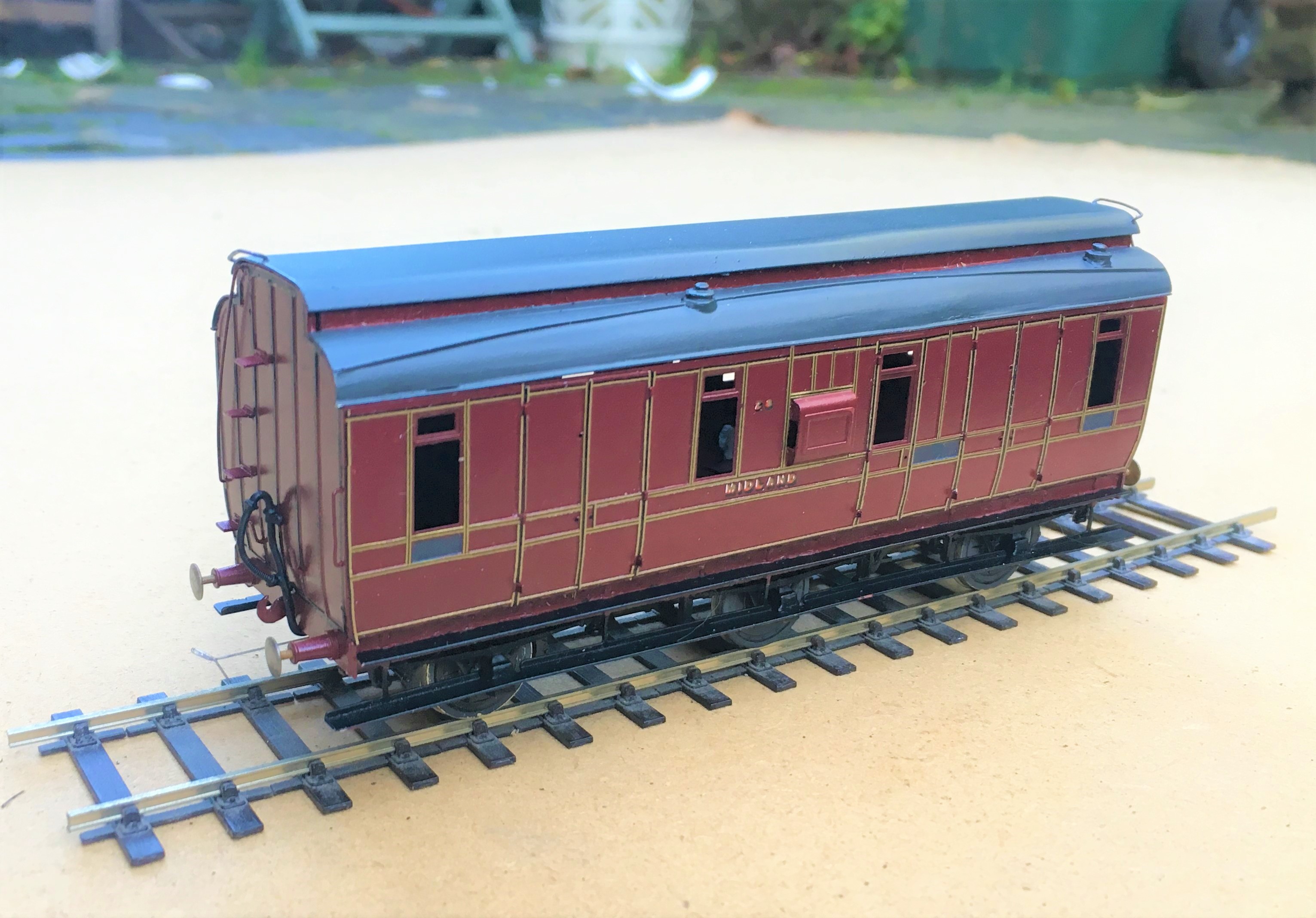
I deliberately left the handrails and door handles off at this stage to make the lining easier but the door hinges still created problems that I will need to touch in with acrylic paints; burnt ochre looks about right. I also still need to block in the black to the head and foot of the sides plus where the lengths of transfer where they crossed – I will do this with a Roting pen as I still feel confident enought to wield this!
So there is still plenty to do, but I am dead chuffed with this and it will soon be finished and ready for service.
Second up is a Lochgorm Models third class saloon that has been waiting for its lining for rather longer. It is a more difficult prospect to line as it has round corners to the panels and, over the doors and windows, shallow arcs. These can’t be formed with transfers as these are straight. I have thus used the transfers for the straight sections and then brush painted the curved sections with cadmium yellow acrylic paint.
If all goes well, the Roting pen can then be used to infill the black to the centre and form the curves across the windows and doors. Lets see!

Catching up on a Tennant
Way back in the mist of time (well 2016), I made a start on one of Arthur Kimber’s kits for a NER 2-4-0; termed a Tennant. After residing at the back of the cupboard for a bit too long (as is the way with my modelling, I do admire those that start something, see it neatly through to a finish before starting another……..!), I have made some more progress with it.
First up with the tender body which is close to finished except for some detailing around its front.
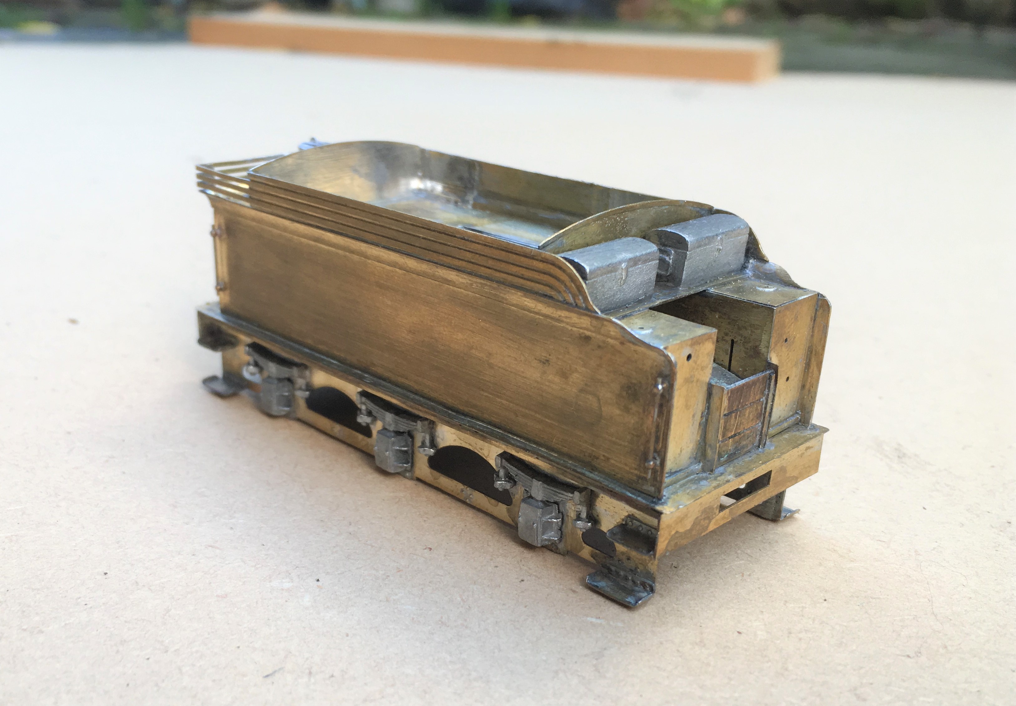
There was a bit of irritation in the building of this; despite being quite a modern kit the rear panel was much to narrow, the buffer beam a bit flimsy and there were some missing details around the front of the tender. Nothing someone raised on Jidenco’s kits can’t sort, but I rather hoped it wouldn’t happen with a modern design!
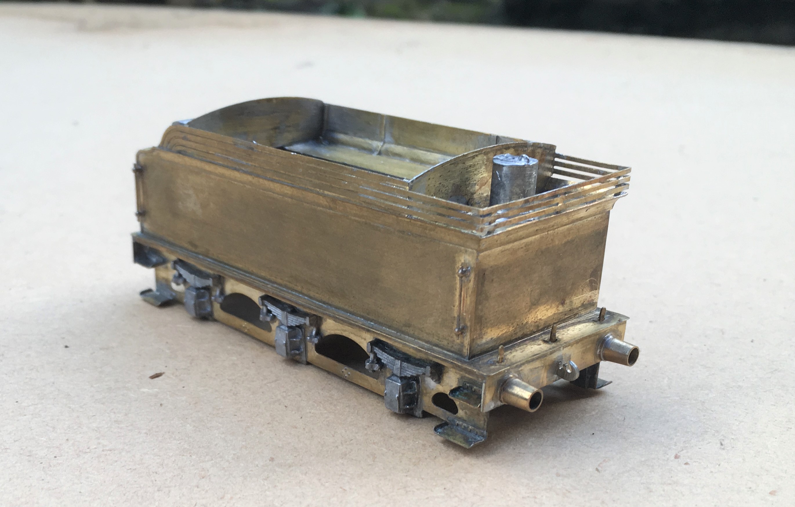
I also found that the boiler was about 0.7mm too long; a degree of filing and fettling has got it fitted. It is fair to say whilst there were these niggles, most of the rest of the kit is well designed and there are a number of neat facets to the kit, the flairs to the tender top for example are pre-rolled and they are very difficult to form without the right presses.
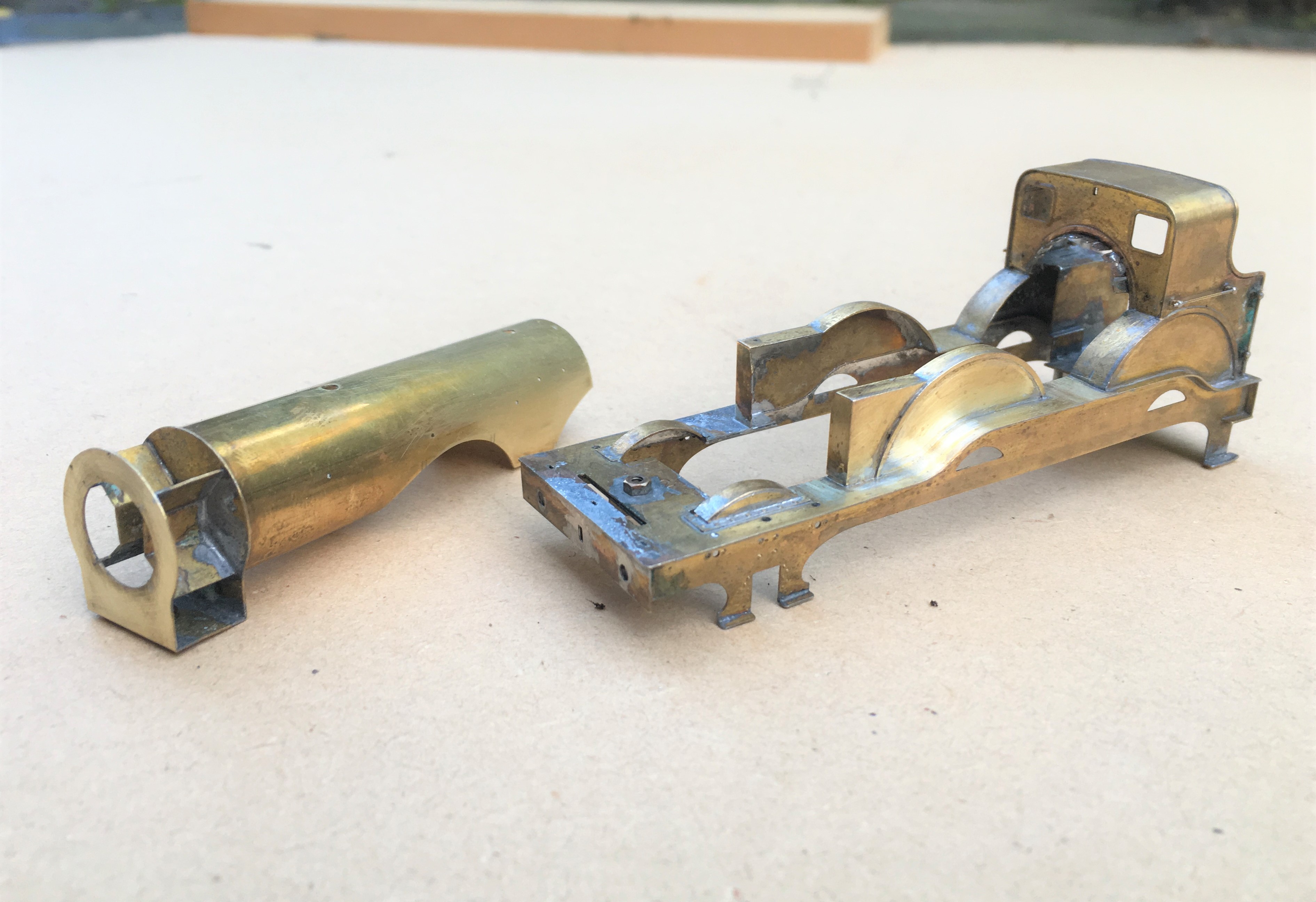
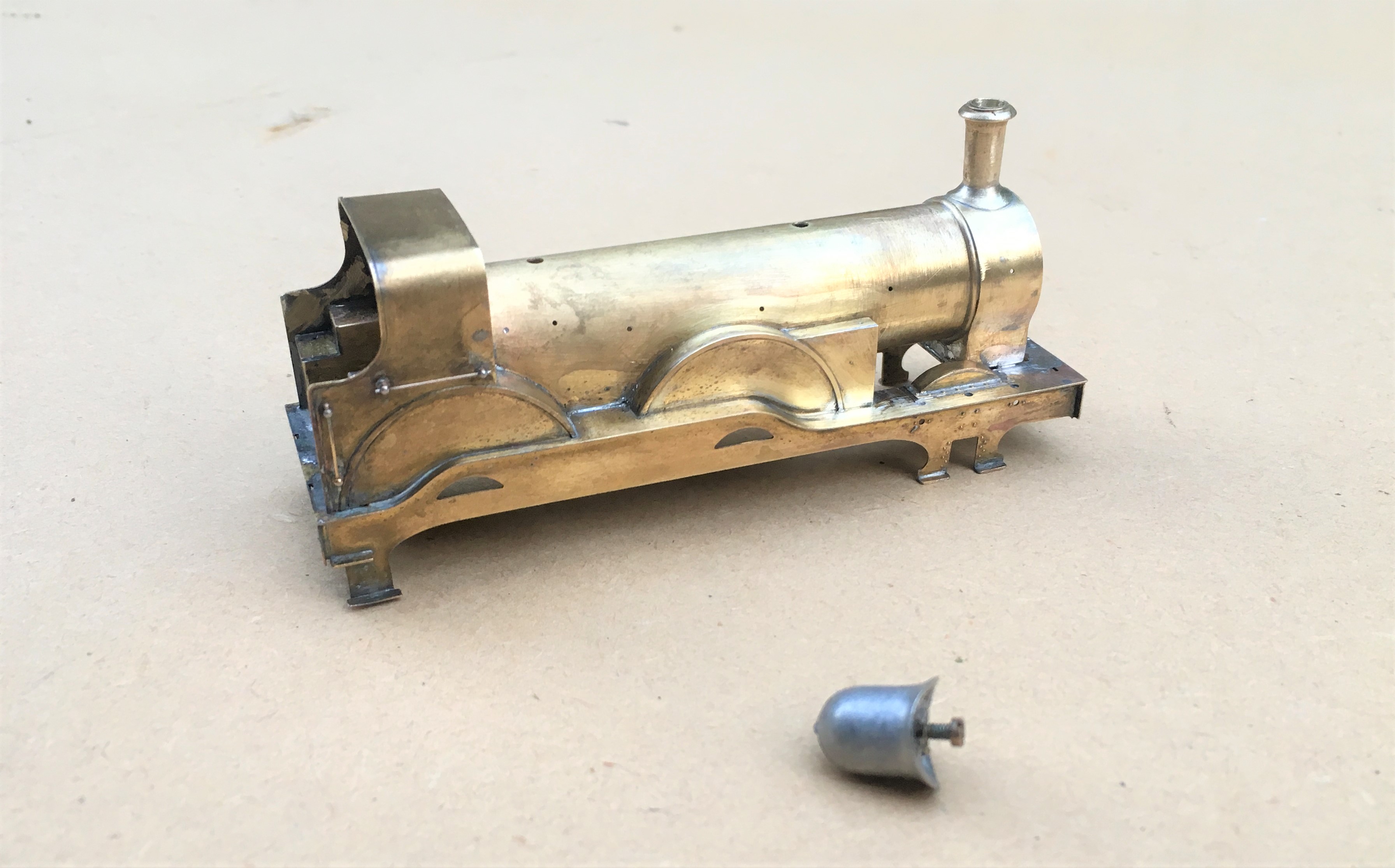
Here she is with the boiler now fitted and the first of the boiler fittings being attached. Something that grates with me on many people’s models is where these do not sit down tightly on the boiler or have overly thick flanges onto the boiler. Given that these are castings, it is understandable that these sometimes happen but they do damage the reality of the model and it pays to address these issues. For this reason, I prefer to solder them in place and am prepared to attack them with a file both before and after they have been fitted.
This does create a problem of soldering the parts in place; they are quite chunky so need a lot of heat to solder them in place and it is difficult to move them about to get them in the right place when they are so hot. I have just started to address this by drilling out the base of the boiler fitting and tapping it to take a 10BA bolt + washer. This allows the the fitting to be moved about until it is in the right place and held tight with the bolt so that it can then be soldered. I am pleased with this little trick; it definitely repays the effort and for the white metal castings, saves the risk of returning them to a blob of metal with too much heat!
One example of a Tennant is preserved, being situated at the Head of Steam Museum at North Road Darlington Station. This has enabled me to take a good number of detailed shots but they are all rather close up they don’t really capture the prototype; so here is one from Neil Dimmer’s collection from the earlish 1920s, at (I think) York. The thin nature of the flanges to the dome and chimney I comment on above can be seen in this.
![[IMG]](https://photos.smugmug.com/LNERSteam/1884-NER-Henry-Tennant/Tennant-E5-NER-1463-2-4-0-Locomotives/i-L5bsMX9/1/794c2272/XL/1463%20Tennant%20E5%20%28NER%20%271463%27%29%202-4-0%20Locomotives-XL.jpg)
This view also illustrates how thin the boiler bands are. Given that this will be painted in NER livery that has lining on the boiler bands I am going to rely on the thickness of the lining transfer to give the impression of the boiler band rather than represent them in metal.

Thirty Seven for Portchullin……
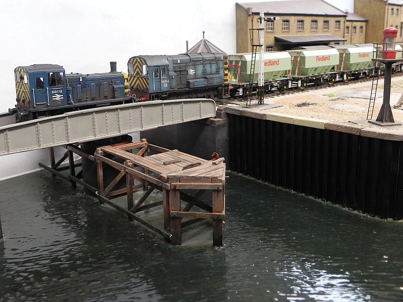
Portchullin is just back from a fun weekend attending the Brighton Model Railway Club’s annual exhibition – its thirty seventh show. Despite efforts, some electrical gremlins were making themselves felt quite severely on Saturday morning such that yet another temporary fix became required to keep the layout operational!
This did lead to some contemplation as to how many more times the layout should go out going forward. As the photograph below illustrates, the layout has made it to some fairly far flung places – Glasgow to Utrecht via Barnstaple, Portsmouth, Newcastle and a fair number of places in between.
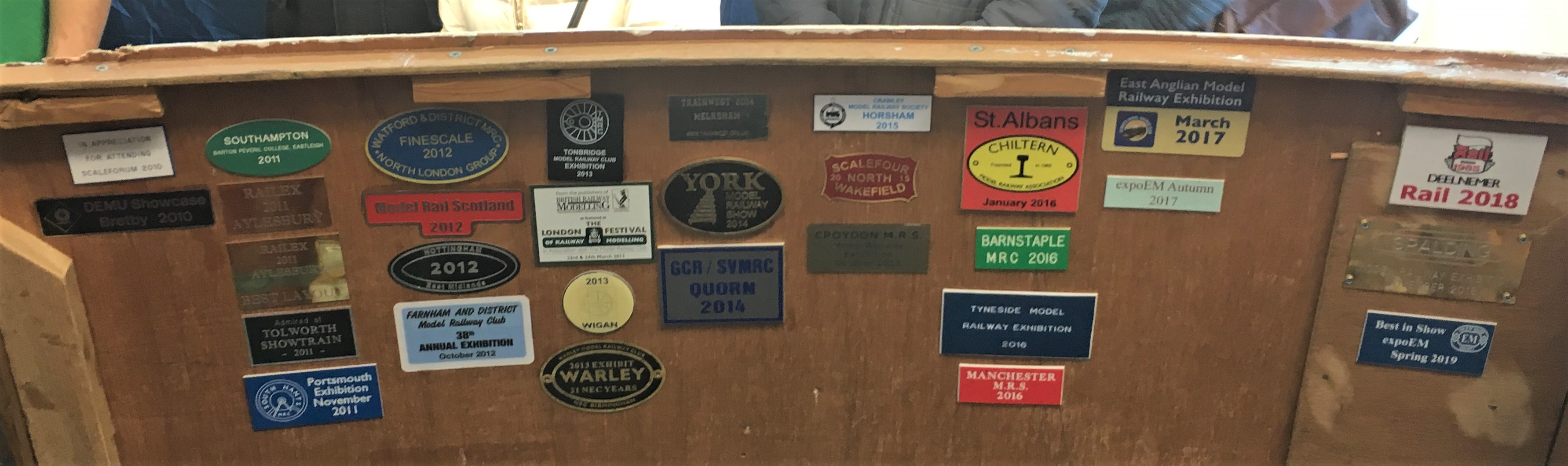
Whilst I have not yet made the decision to retire the layout, and will give it a fairly thorough rewiring to ensure that the issues experienced this weekend fare overcome, its retirement will come in time. Don’t worry if you wish to see it again, there are still a couple of confirmed bookings over the next two years (starting with Perth in June 2020) and a couple more are likely.
Glenmutchkin is progressing slowly and will eventually replace Portchullin but as a taster of things to come (with some compromises, I know the livery of the Jubilee is incompatible with the fully lined coaches!), here is a video of the new (if older) order.

That was the weekend that was….
Well the layout made it to and from Scaleforum – possibly I did too!
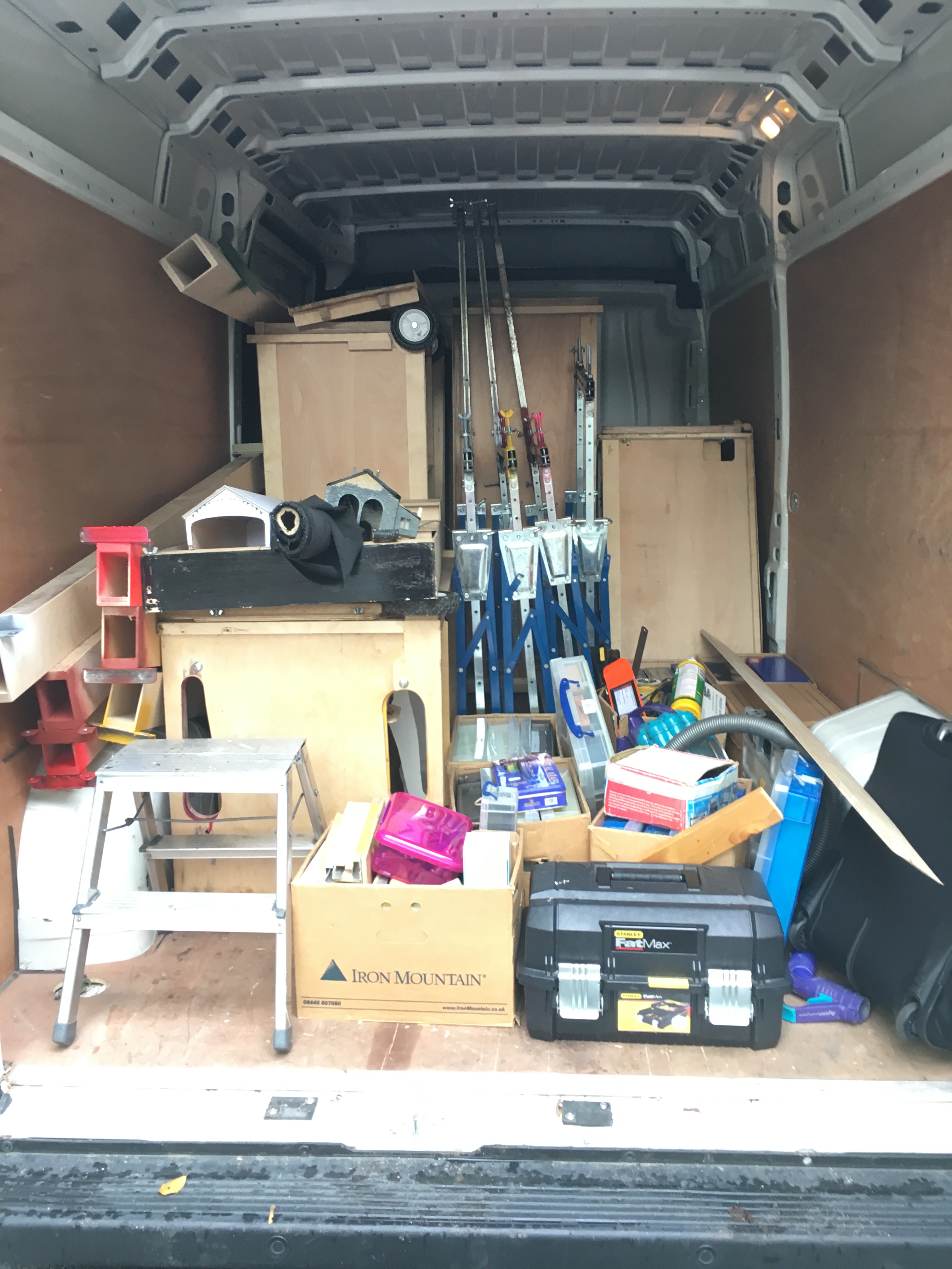
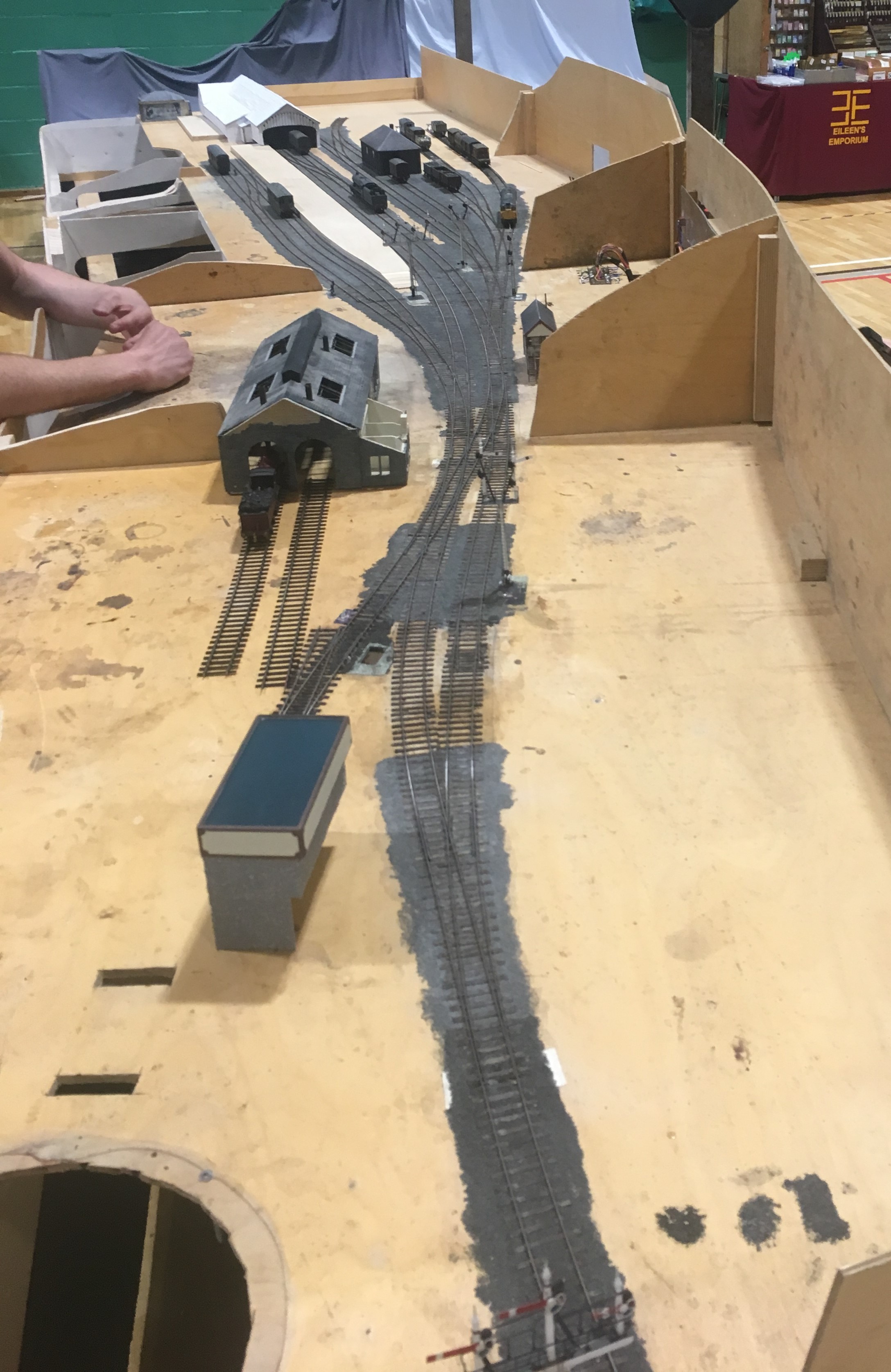
Last Friday, the inside of the hire van looked like this. Whilst the cases worked a treat, the dismantling of the layout from being set up on my own took a long time – much longer than I had hoped or expected.
Once at the venue, I was able to press gang some “volunteers” to erect the layout and this was much easier.
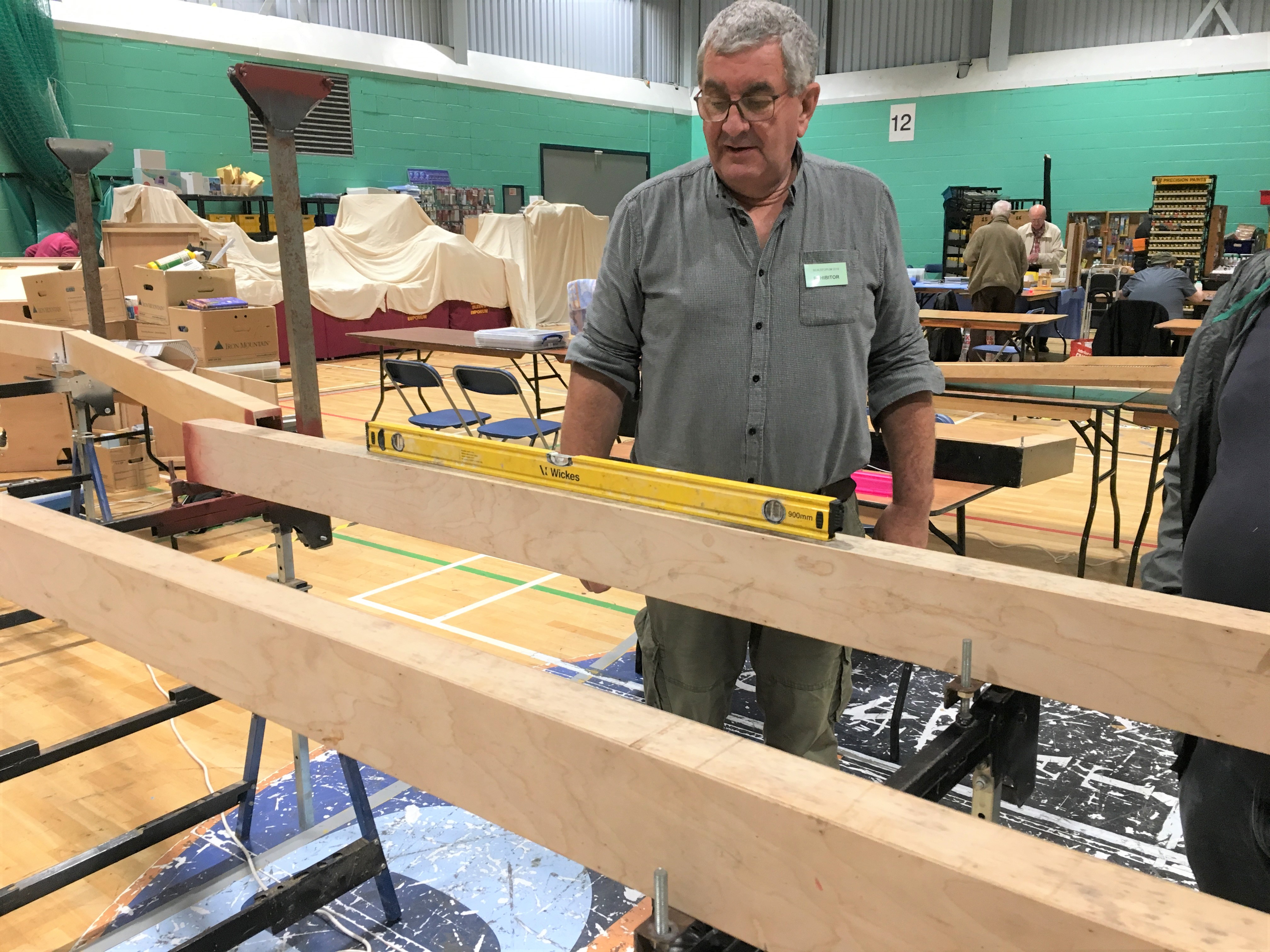
Getting the beams levelled up was speedy even though none of my press team had any experience of my logic! Indeed, with their help, it assembled itself quicker than Portchullin does although the jury is out in my mind as to whether this is simply because it as yet has rather less on it!
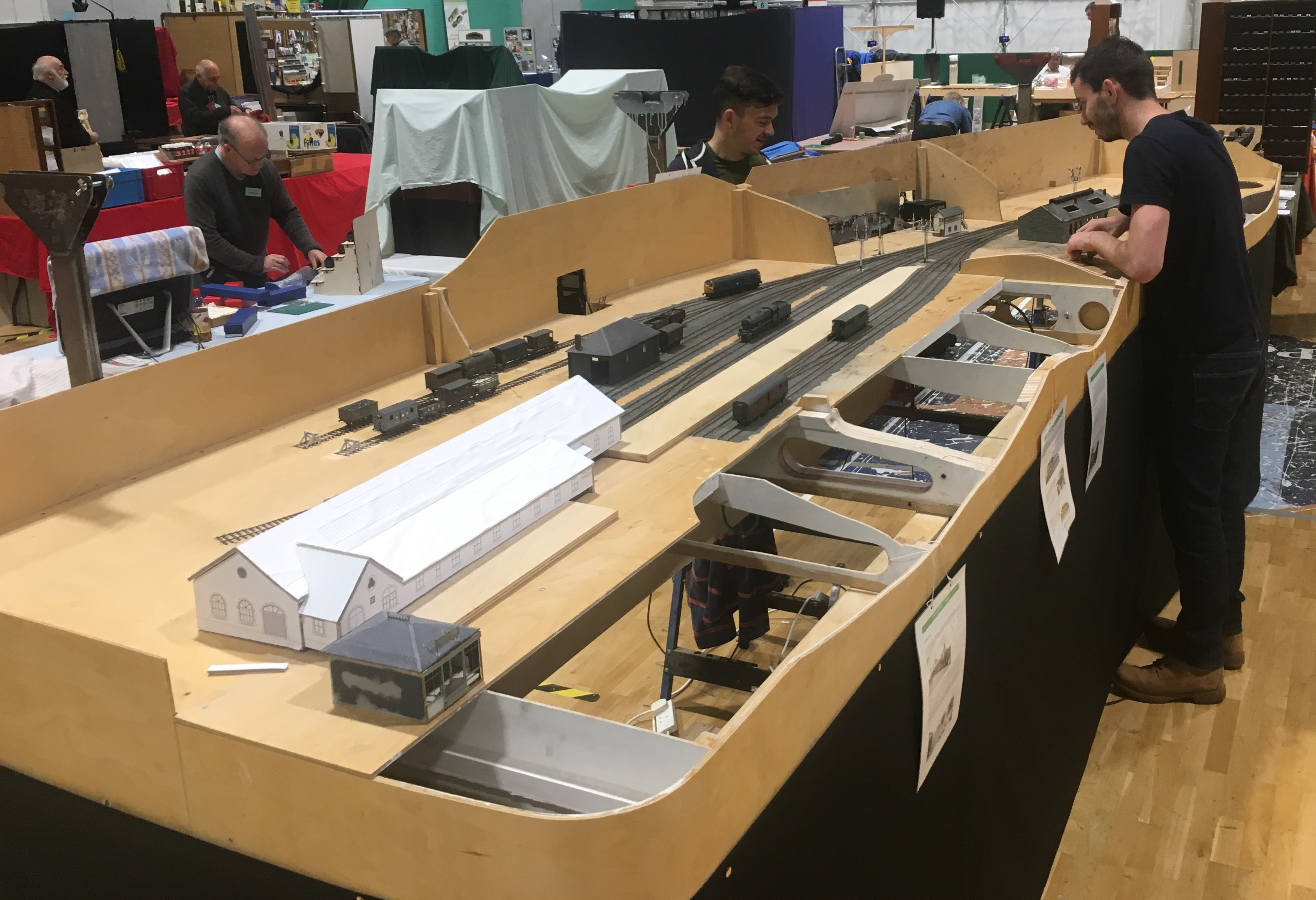
The layout’s size quite quickly became apparent; especially its depth – as can be seen here with Chris in the background for a sense of sale! Please don’t tell my wife this is actually quite big, I have been telling her it is pretty normally sized!
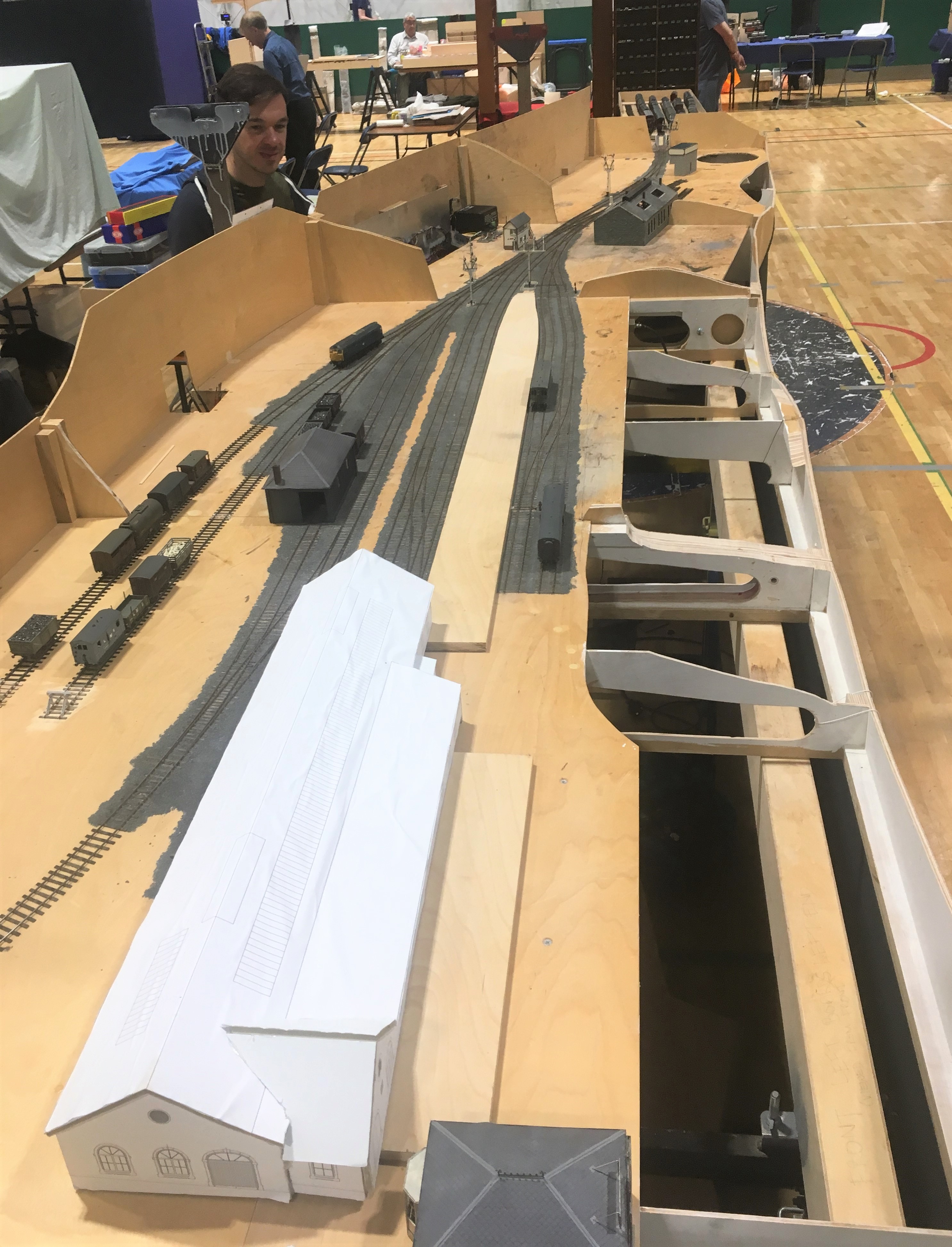
I did not manage to get front side all that often so I have only fairly limited numbers of photographs. Fortunately Samuel Bennett has come to my rescue and has provided a number of photographs to show what it looked like to the visitor.
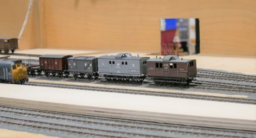
We only had three correct Highland locos chipped up (and one of these decided to sulk after a couple of hours!) so we did break out the blue diesels to make sure we had a fully operational layout. Above there are a few of the locos awaiting chipping on shed and below we have the scene 50 years later!
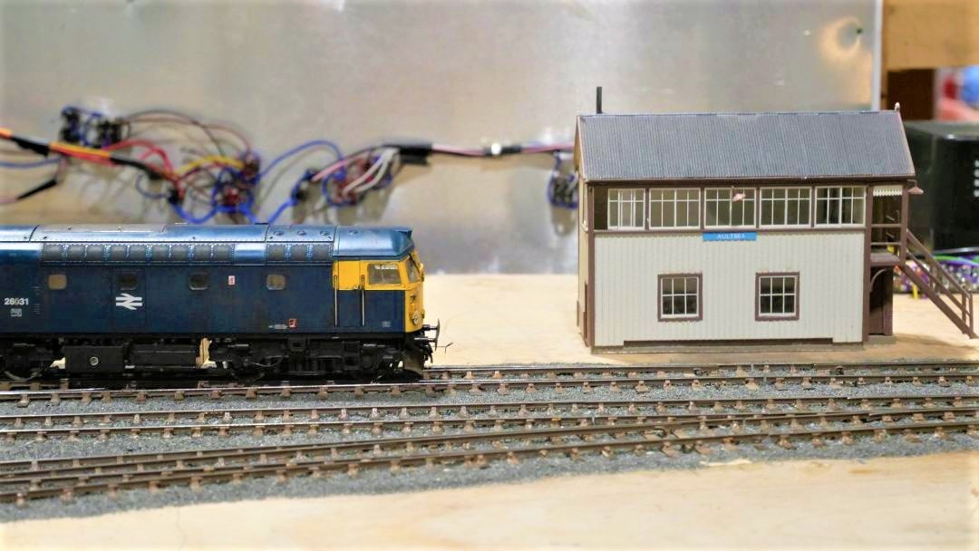
……..and below is simply confused!
Although the layout did not operate perfectly, it did behave much better than I (and my operating team) had feared! The two page list of faults and issues to resolve with the trackwork, wiring or stock is a fraction of the list that would have existed after Portchullin’s first outing (if I ever had one!).
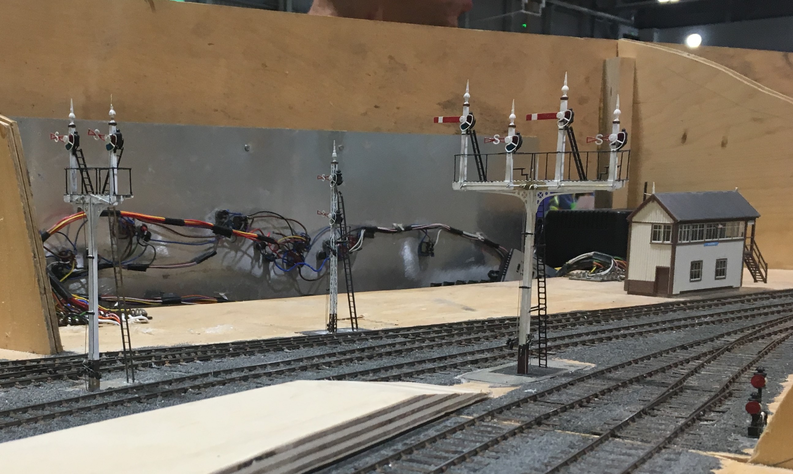
The signals received a lot of comment, even if there was one missing because I managed to damage it as I was packing the layout. There’ll be another post on these soon.

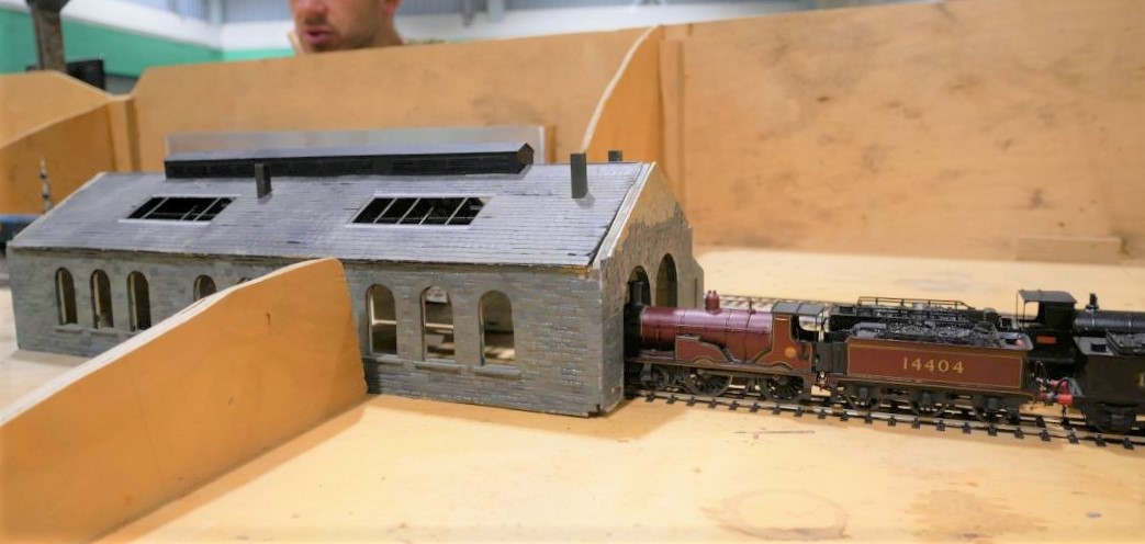
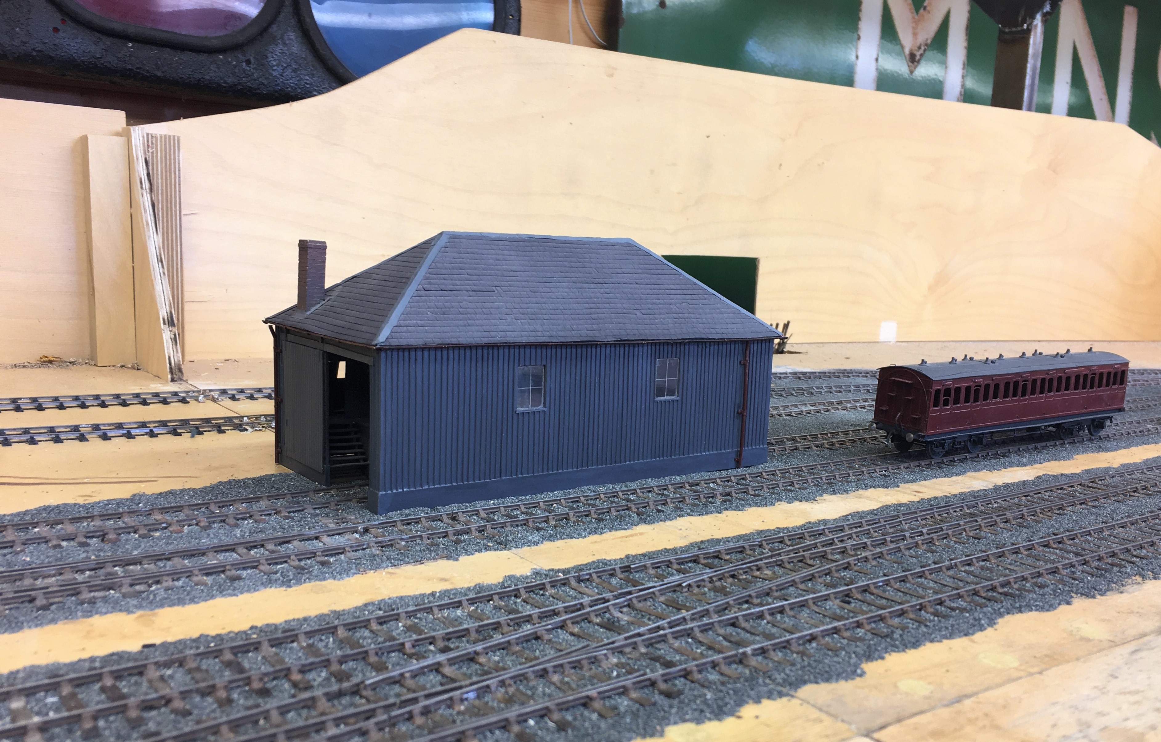
Putting a Backbone into a Shed
The advantage of a railway company using standard building designs is that you can get to use them more than once. Thus Portchullin’s goods shed will be getting to have a new lease of life on Glenmutchkin.
I think my goods shed is the oldest model that I still have and over the years it is fair to say has suffered. Some of this is simply the thirty six shows that it has done with Portchullin (hell………thirty six shows…….!) and almost as many years, as I was about 17 when I made it. However the main issue was the manner in which I built it, with minimal bracing over the top of the entrances. This has lead to it breaking its back and despite several attempts at repair, these have never been long lasting. So it is time to do it properly to allow its reincarnation on Glenmutchkin.
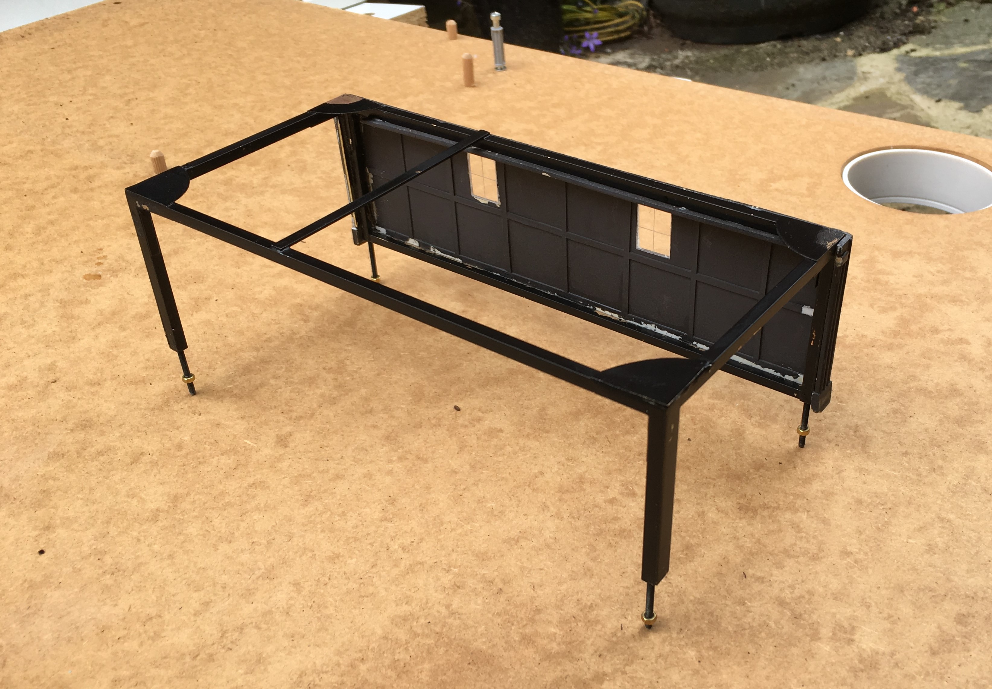
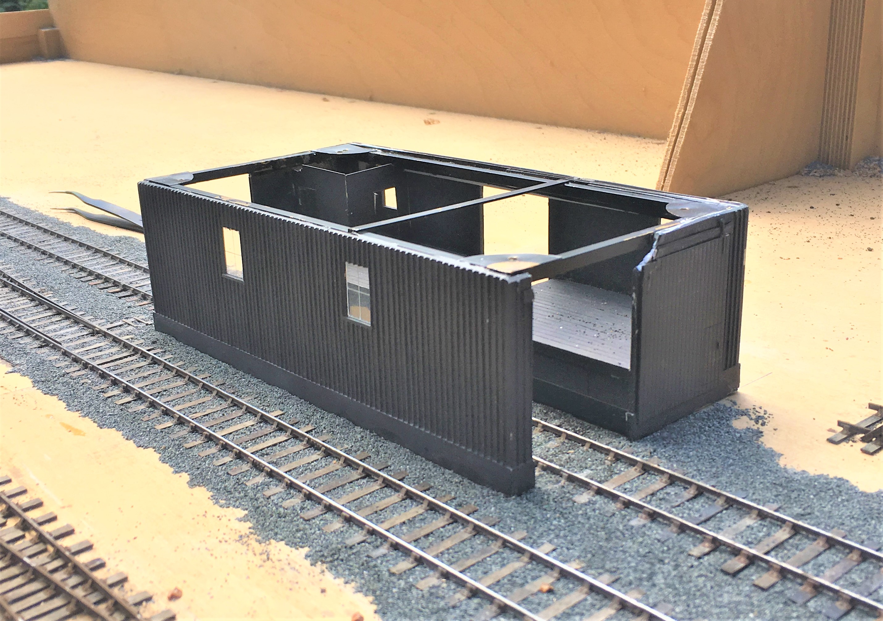
The key to the repair was to introduce a metal skeleton frame inside the model to strengthen it – particularly across the rail doors. This is something I now tend to do at the outset with any largish building I build to contain warping. The frame is invisible from the exterior – the view above shows the frame that I made with the first side attached.
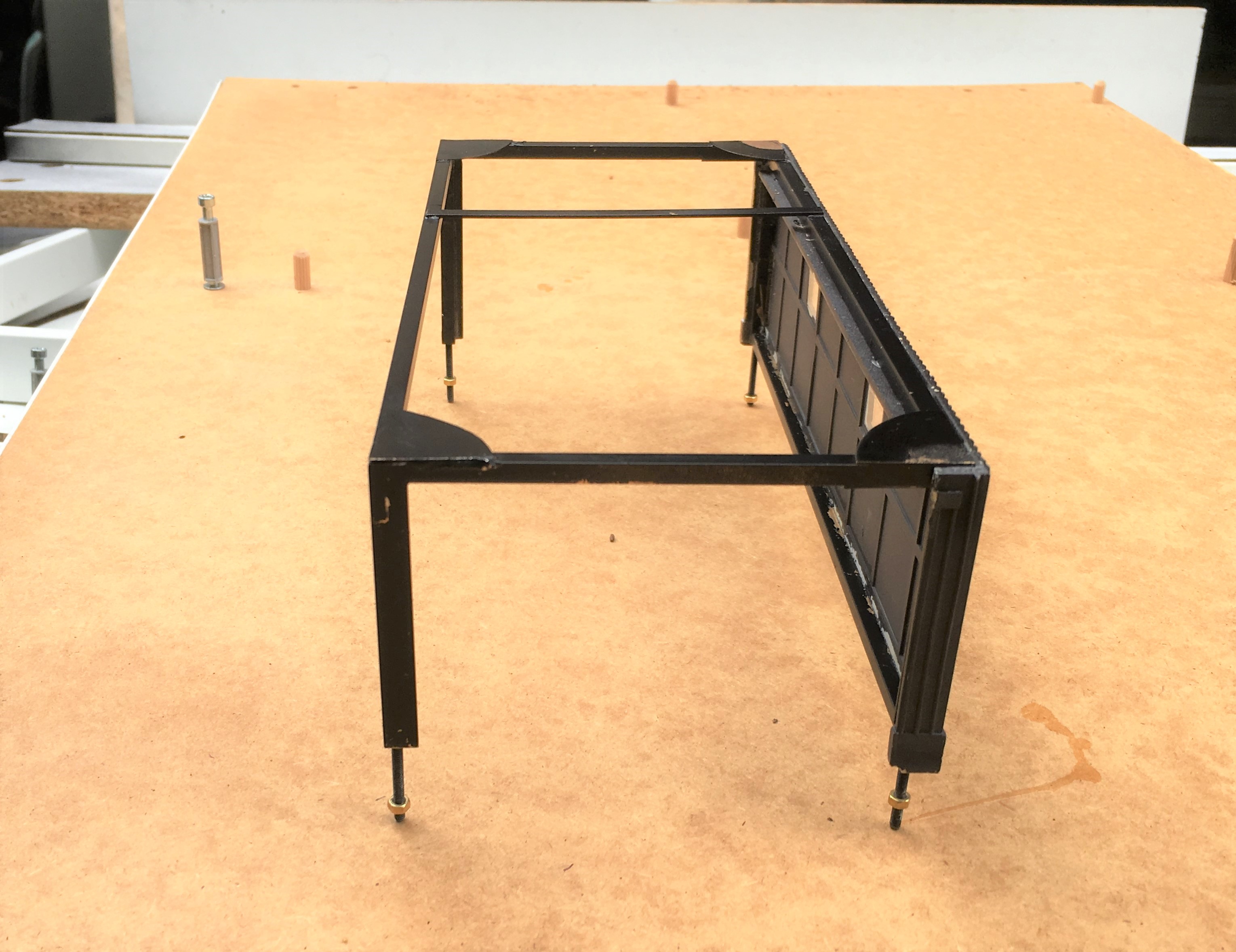
The frame was made with some 3mm square and oblong section brass, with gusset plates – there was a fair amount of metal so it got close to blacksmithing at one stage.
Once the frame was inserted, the model was given an overhaul to repair the other dinks and marks that it has acquired over the years. There were a fair few, as can be seen.
I also to the opportunity to install gutters and downpipes; something I had been meaning to do since I was 17………a bit of a shameful shortfall, given I am a chartered building surveyor!
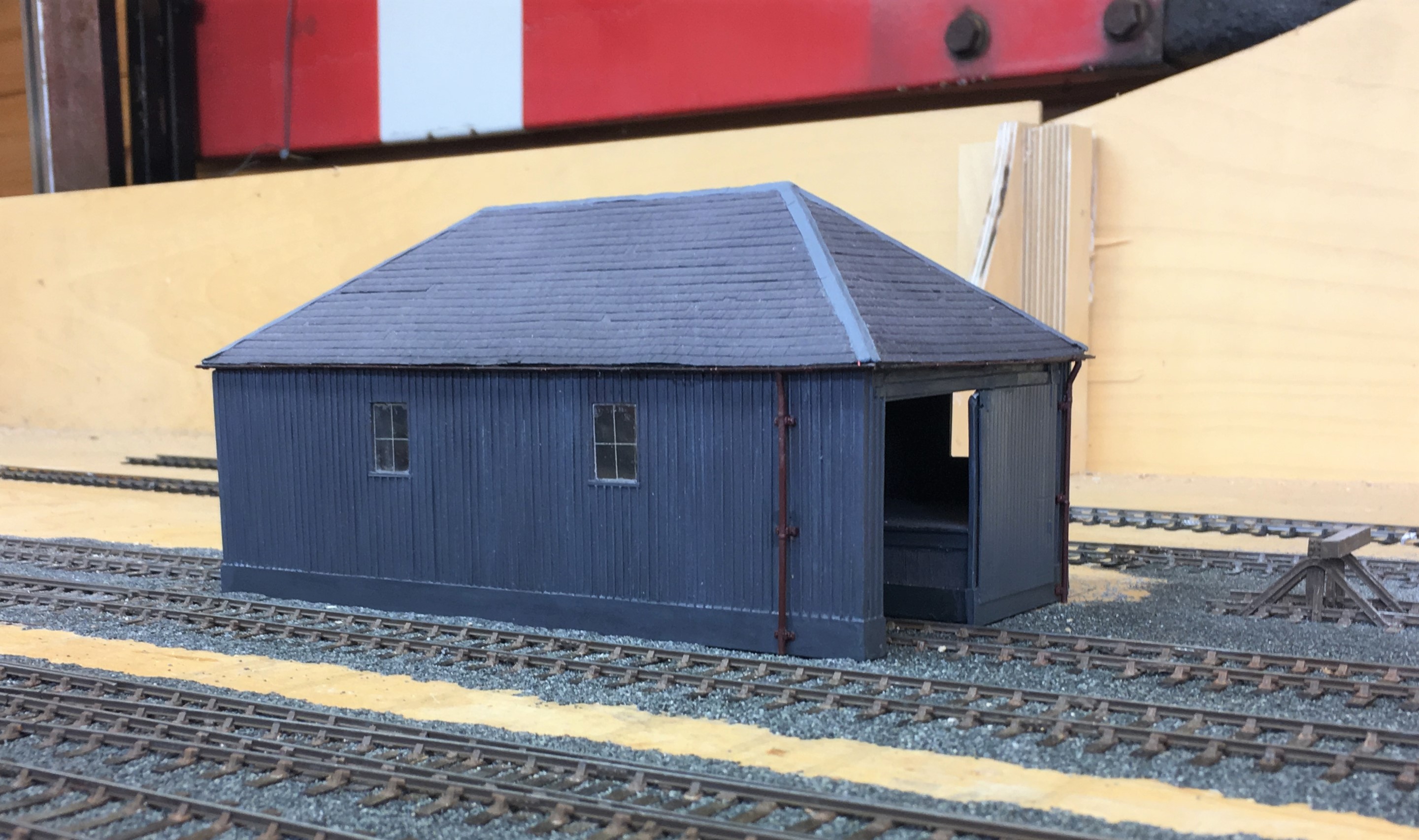
I am pleased with the results and the model is now much more robust so it should do at least another 36 shows! Whether its owner can will be kept under review!
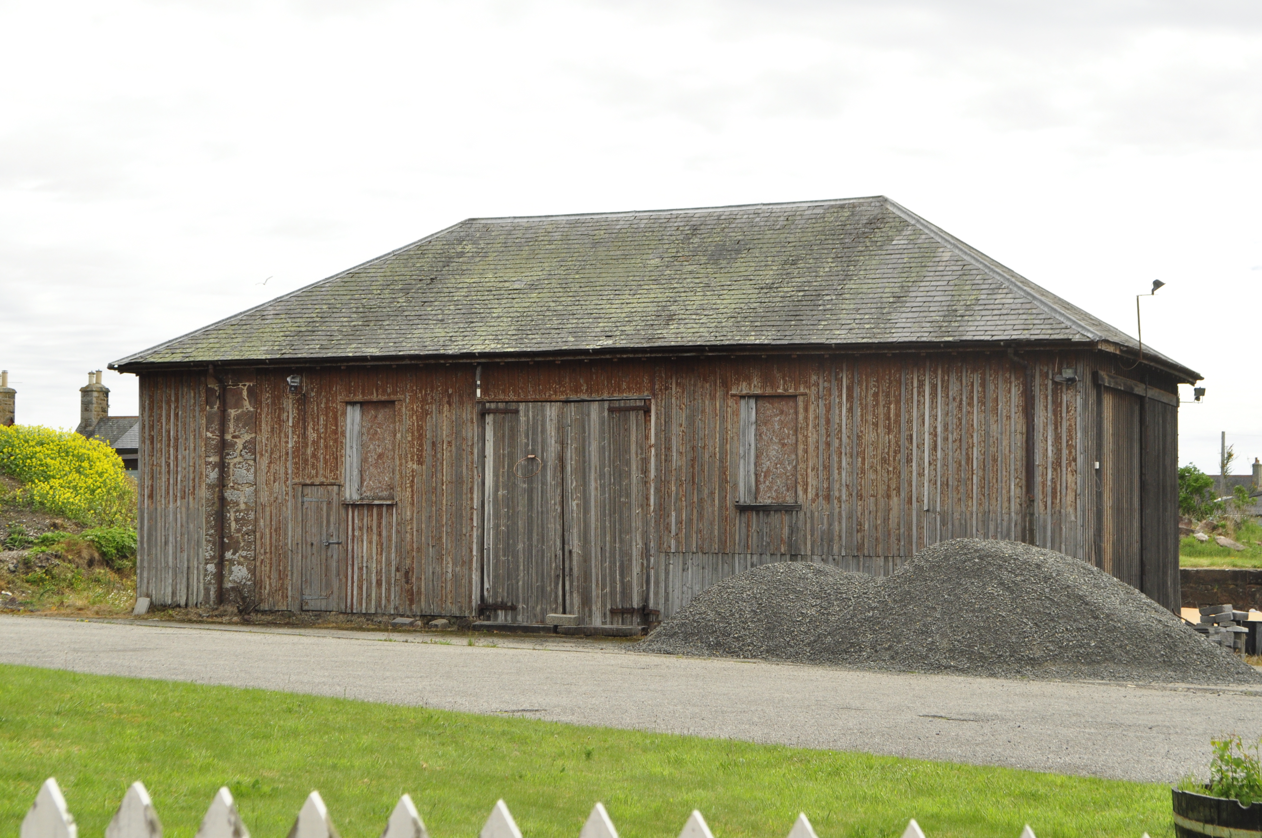
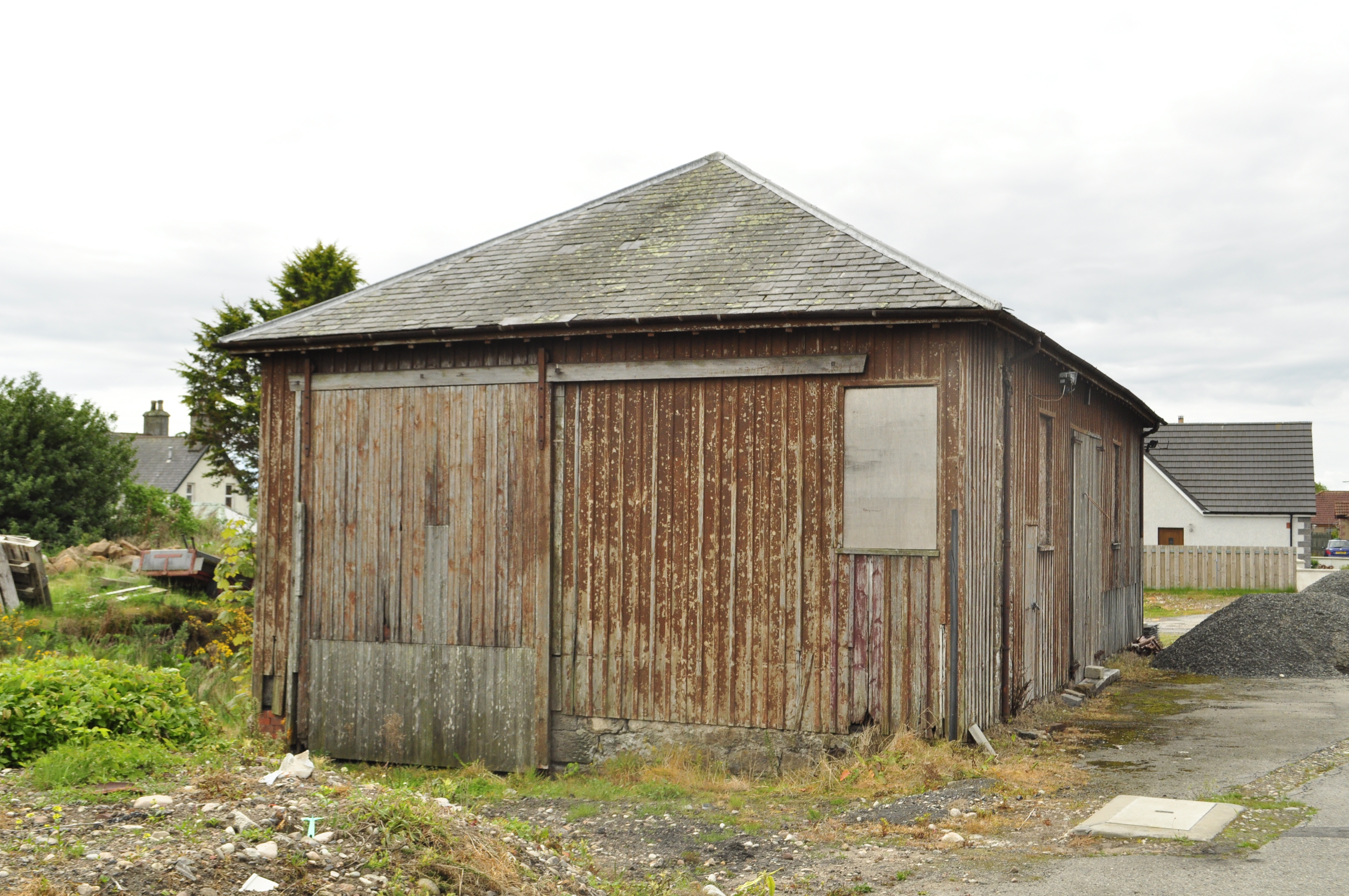
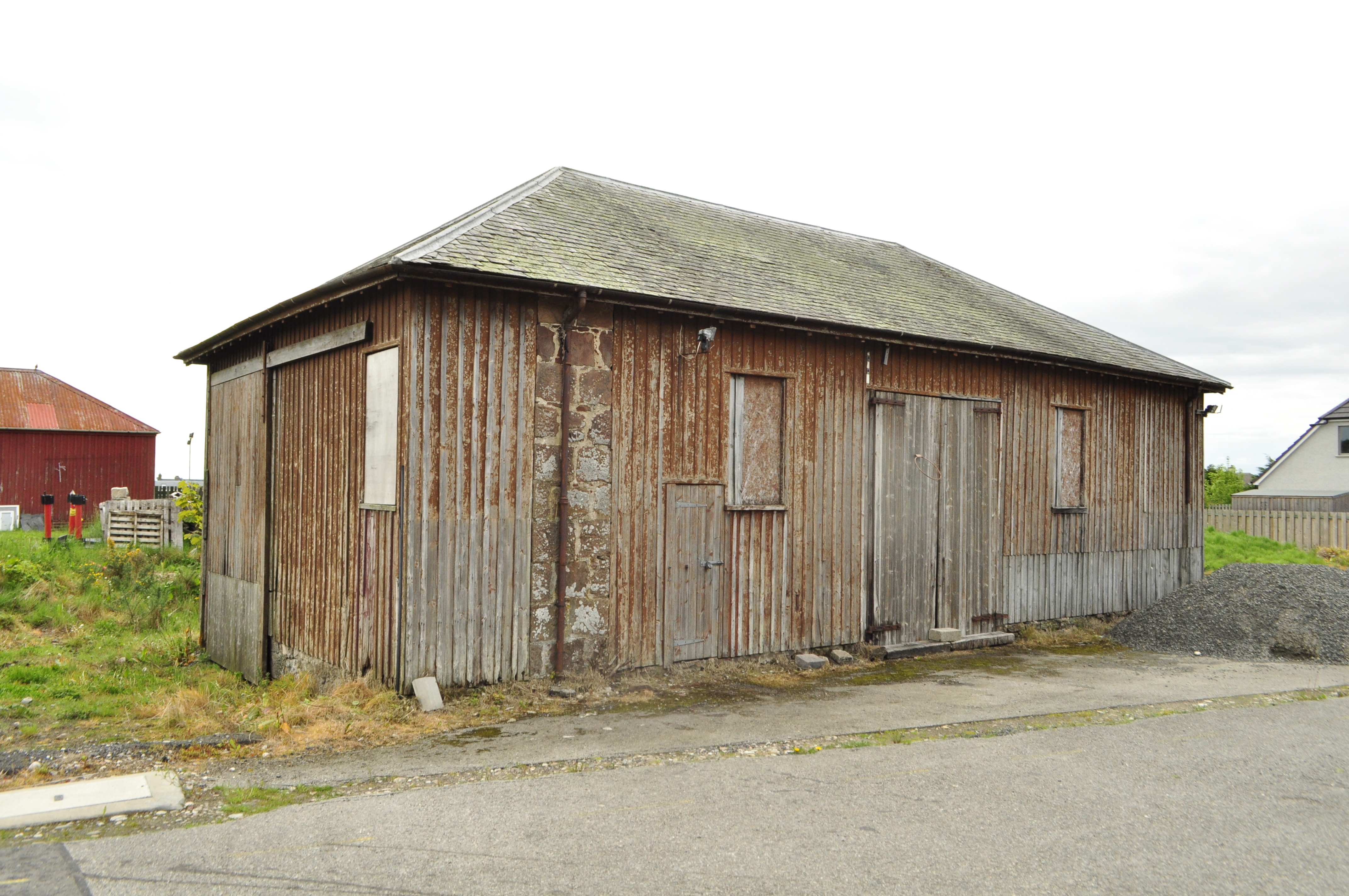
My goods shed is based on the Orbach drawings of the shed at Garve (the August 1952 edition of the Model Railway News). The prototype was swept away in the 1970s and whilst there are a pair of the smaller sheds still remaining (notably at Brora), there are no longer any of the standard Highland Goods sheds left. The last to go was in Golspie about two years ago and I did manage to both photograph and measure it before it went. Here are some views of it before it was demolished: