Blog Archives
Swapsie – A Signal for Nampara for Hendrawna (Part 1)
Swapsie – the childish act of swapping things according to Wiktionary.
Do you remember at school swapping a Top Trumps set for a the latest Hot Wheels car or similar? I do! I remember getting roundly b*llocked by my mum for not recognising the value of things I was giving away and (metaphorically I am pleased to say) swapping gold bars for glass beads almost like the Incas and Cortez.
In the world of toy trains, the same happens and is very useful where someone can offer something that you don’t have (or find difficult to make) in return for something you do have. This is one such example. Sitting next to Duncan Redford at an EM Gauge Society/Scalefour Society skills day a few years back demonstrating signal construction a barter was arrived at whereby I would build Duncan a signal in return for him doing some 3D design and printing. I think it is fair to say that neither of us have rushed with our respective shares of the bargain but with the next ExpoEM only a week away, I have shifted into gear to finish the started signal that was my part of the deal.
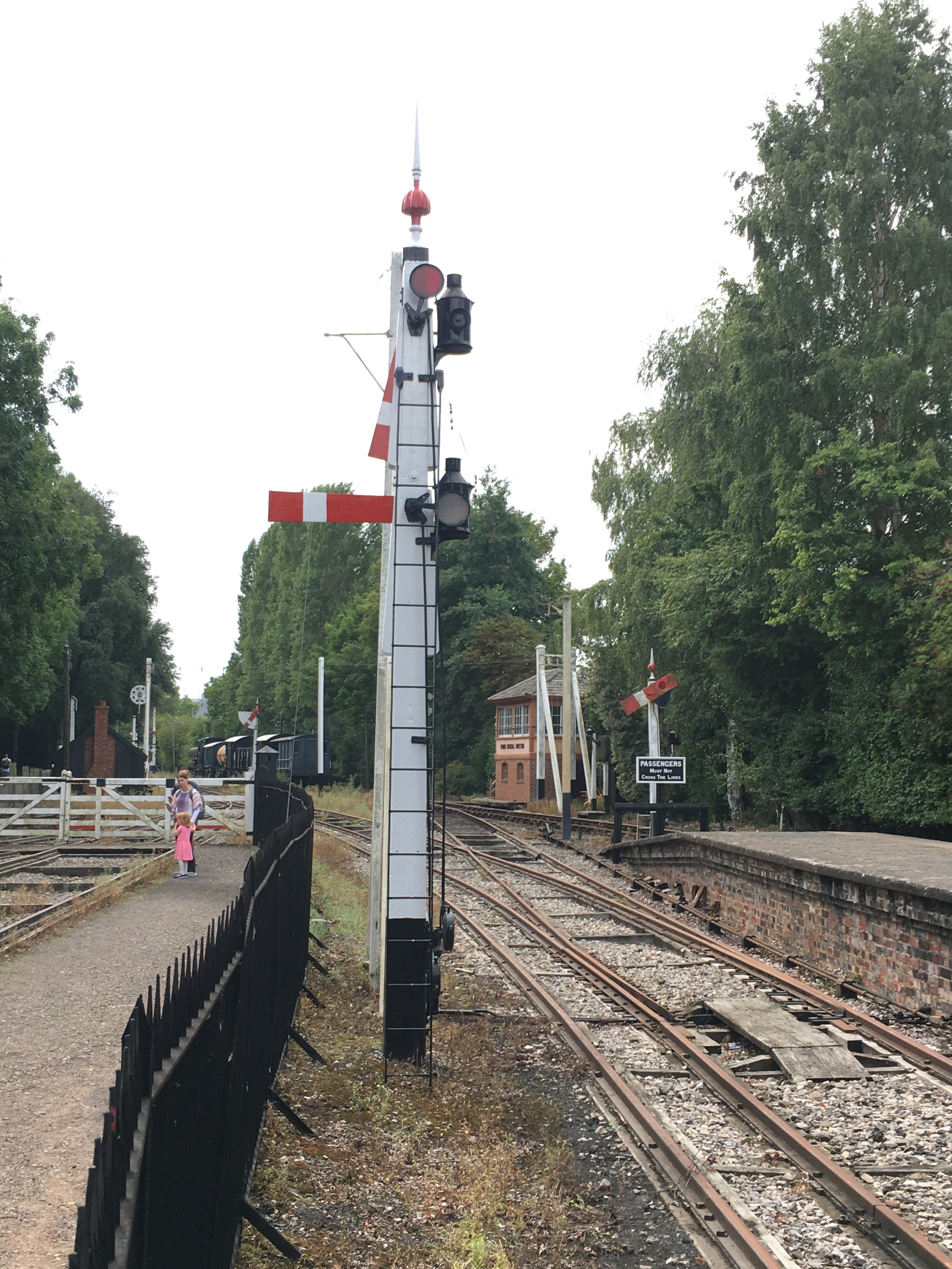
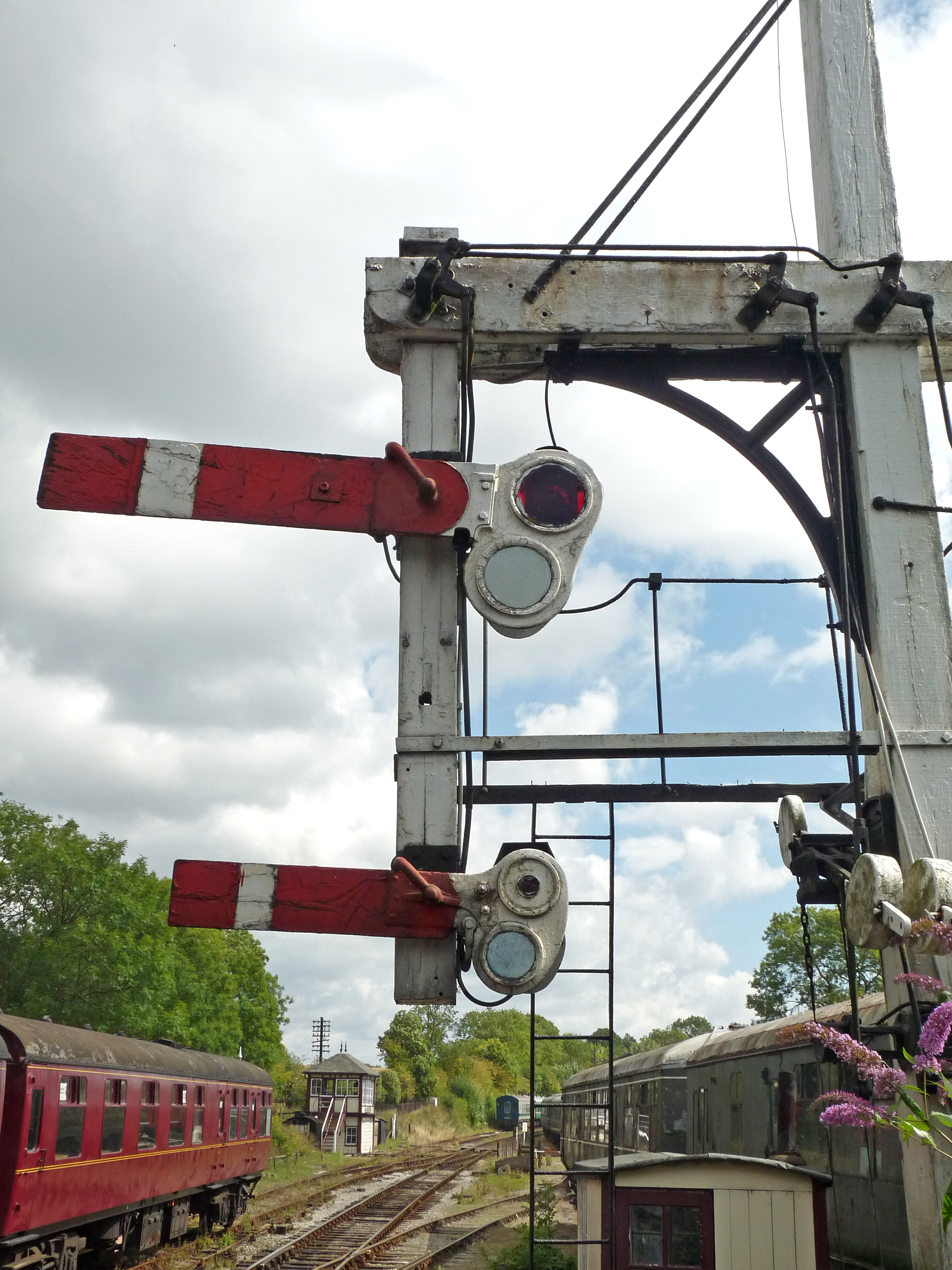
Duncan is building a GWR broad gauge era layout and wanted a close replica of a signal that the GWR Society has recreated at Didcot, but adjusted to have only a single arm. So after coming out in cold sweats about the idea of modelling anything GWR (!!!) I took a look at it. Like many signals, there are differences and similarities with other signals but after a bit of study it became clear that it was sufficiently different that a site visit to Didcot to be required.
Having measured it up including, when no one was looking, a climb to the arm/lamp to measure it, I came home to draw it. I was shocked to find that it was tiny; 3mm/1foot at best and I had a panic attack -had I mucked it up and mis-measured it. Obviously, being a professional surveyor I could not possibly have done that, could I? After a few months, the fear that I had niggled on me and so came about site visit number 2 and a further climb up the signal ladder. Nope, it really is tiny – both the post and the arm are notably smaller than I am used to.

There are several unusual aspects to the signal; the one glass spectacle plate, the tapered arm and the very pronounced stiffening around the slot in the post were all going to be key to capturing the character of the signal. So out came the computer and a small fret was added to an etching order for the arms/spectacle plates. I then formed the basic post from 4mm square section brass which I filed to a taper with a 2.5mm cross section at the top.
Despite having built a few slotted signals already, they are still pretty difficult to get to work well. The difficulty that I have had is to get a soldered joint onto the arm spindle when it is encased in the brass post around it that acts as a heat sink. On a number of occassions the joint has broken and the arm no longer operate. I was determined this was not going to happen this time and have adotped a different approach, by assembling the arm first and then mounting it within the post whilst this was being assembled.
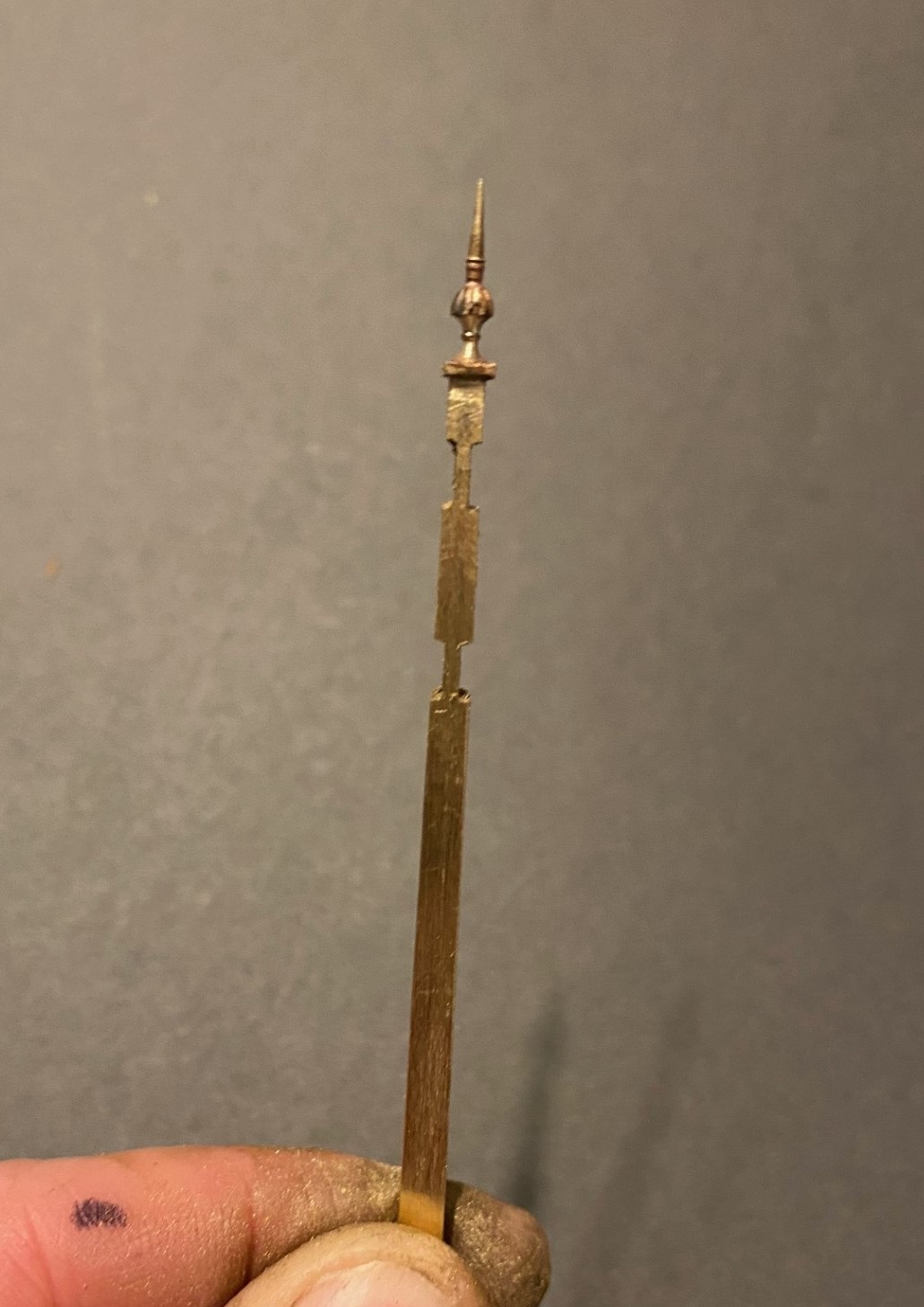
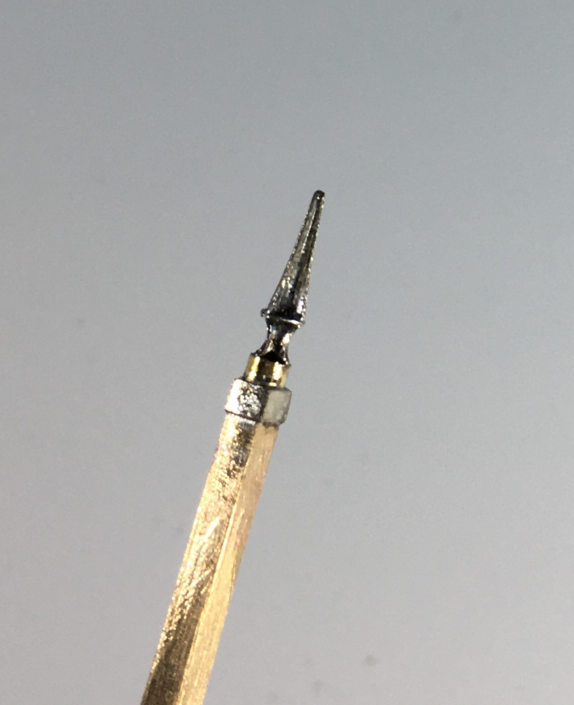
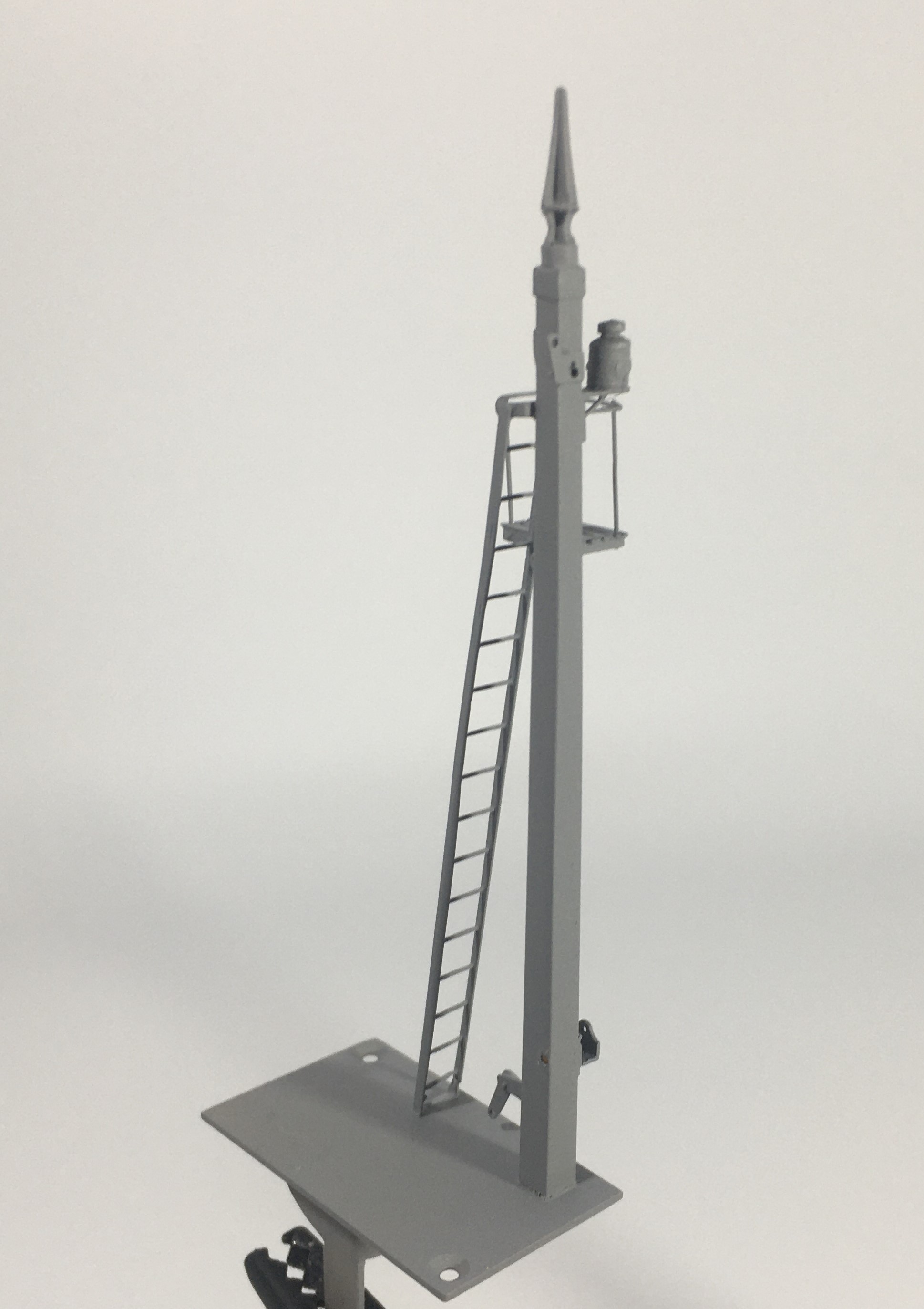
I had filed some 4mm square section into a taper to form the full length of the post. Even though I was about to cut a section of this out, it is necessary to form the full length of the taper so that it is consistent across its full length. Once I was happy with this, i filed two pairs of slots in the outside of the post on oppposing faces. The depth of these was such that the tongue between them was the correct size for the slot in the post. I chose to mount the finial at this stage, with some 296o solder and a lot of heat (from a minature blow torch). This is what it then looked like:
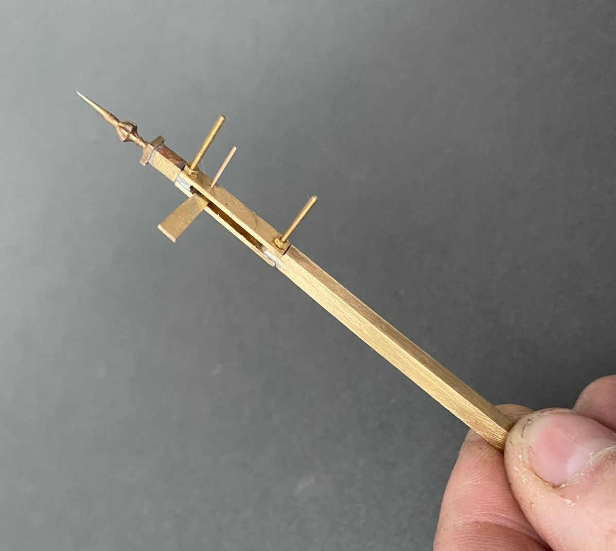
Next, I cut away the block of post that sits between the two filed sections to create a hole in my post. As there is around 2 hours of work to get the post to this point, it is a bit nerve racking chopping it like this! I then cut a pair of 1*4mm brass plate lengths to sit on the tongues and drilled both to receive a 14BA bolt. This was threaded through the first of the plates and adjusted until this a continuation of the taper of the post – this entails some filing of the metal to make the outside face match the post and plate match. It was then soldered in place, again using the 296o solder and a blow torch, to look like this:

The photograph above shows that these plates were wider than the post, in practice the prototype acheived this by planting timbers across these sections but it is easier to do this by way of using the sider plate material.
Temporarily mounting the second plate enables the hole for the arm spindle to be formed through both parts of the arm. The arm was now attached to the spindle with more use of the 296o solder and the use of a couple of minature washers either side of the arm so that I could be confident that the joint would hold.
Releasing the second plate now allows the arm/spindle assembly to be inserted and any adjustments made to ensure that it can move freely in the slot by securing the second plate in place with a 14 BA nut. The nuts and bolts are scarificed in the build by leaving them in place for the next step because once I was happy that it was correct I soldered the second plate in place including the nuts and bolts. This time I used 145o solder which meant that it would not disturb the first plate as I was doing this and this is what it then looks like – a slotted post with an arm within that is firmly attached to its spindle!
More to follow; including the second piece of bartering that I know someone is looking out for progress on!

And now a Midland signal…..
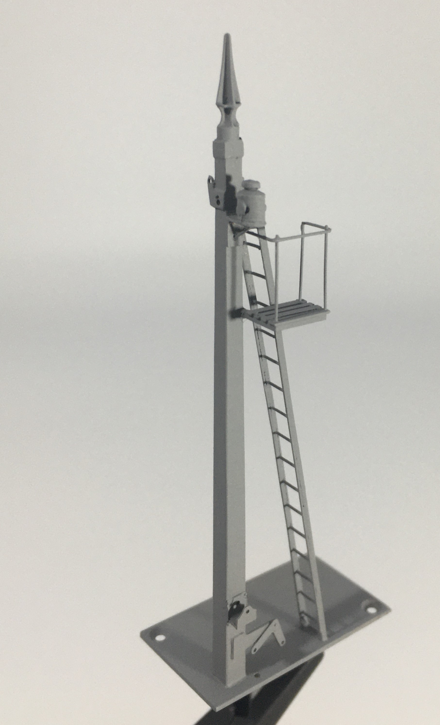
Whilst the NER signal from my last post gets itself painted, I turned my attention to the next few signals – in this case these will be Midland lower quadrants.
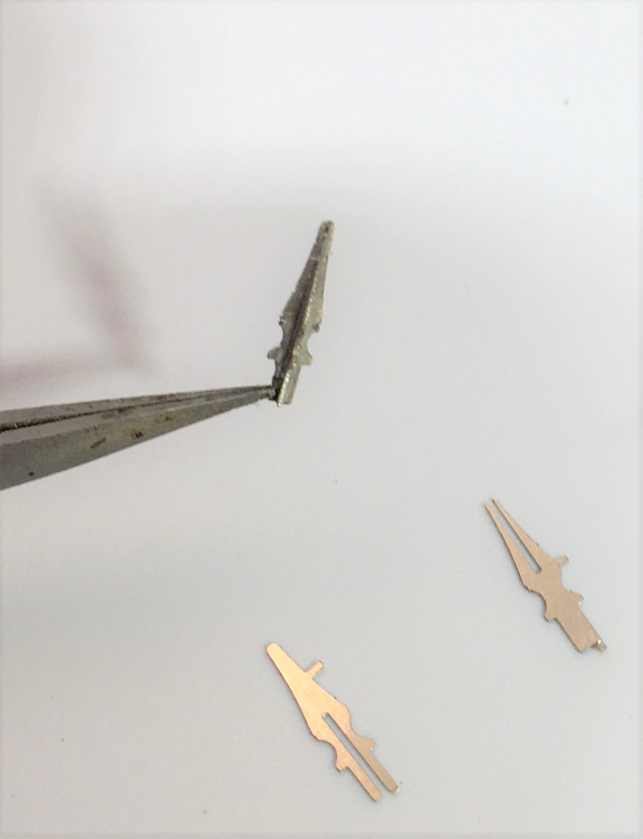
A lot of the character of a signal is in its finial and if this isn’t right then the model won’t convince. In addition, they are also very vulnerable so need to be durable. Therefore, my conclusion is that white metal finials do not cut the mustard – they are too delicate and too clunky. Thus, in this case I decided to make my own – I came up with this which starts with with some interlocking etches:
And then a bit of brass tube as a collar at the base
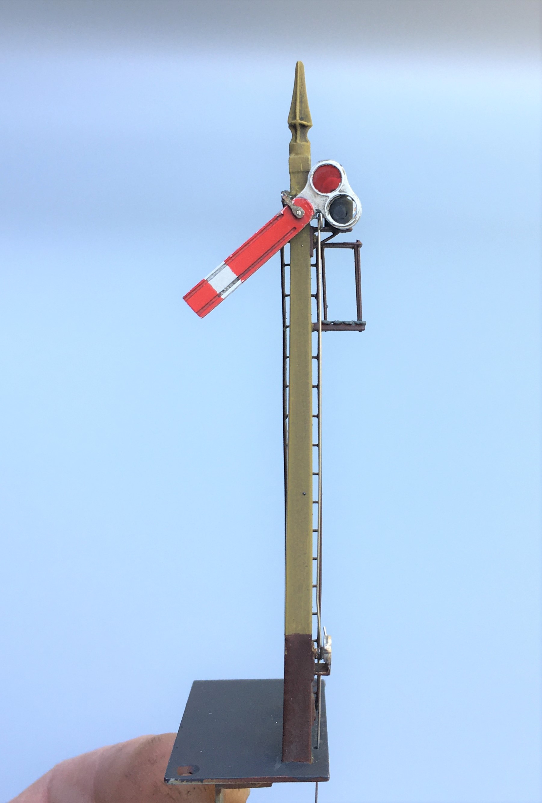
The Midland’s style of signals do have a few idiosyncrasies; one of which is the way that blinders are fixed. Instead of being fixed to the spindle these are secured to the arms and wrap around the lamp. This can be more clearly seen in the photograph below.
The other key change was in the manner in that the arms are secured to the posts. Instead of being pined through the arm and secured at the rear, the Midland used a bracket to the front of the post with a plate that wrapped around to the front of the signal to support the arm to the front. This can be seen in this view of a rather nice gallows signal at Butterley.
The bracket can be seen in this view below and I then created a pin that fitted into the bracket and slotted over the spindle.
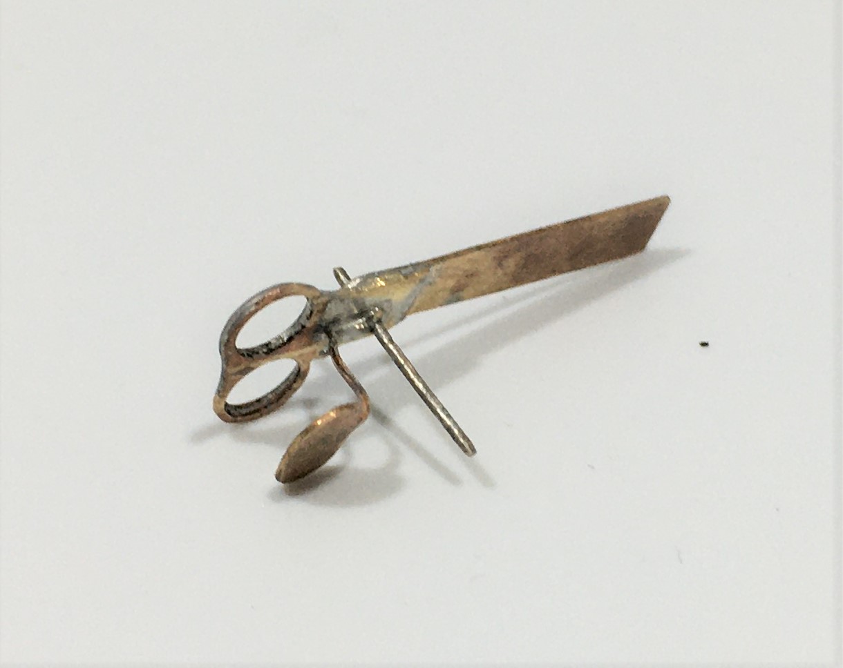
I have bought a new light box for taking photographs in. Whilst I am still getting to grips with it, when it works it does produce much improved pictures of models. These almost look like an images of a 3D model on a computer screen. The pliers at the bottom of these views do rather give the game away!
The Midland were a bit odd in their choice of colours for their signals. The posts were “primrose yellow” but this quickly dirtied to something akin to cotswold stone is what the book says, so this does give something a little different. This is my representation of this with a decent dose of smokey dirt – when you look at contemporary photographs many signals were not only dirty but entirely smothered in smoke. I haven’t gone that far yet, but its going to need to be done!
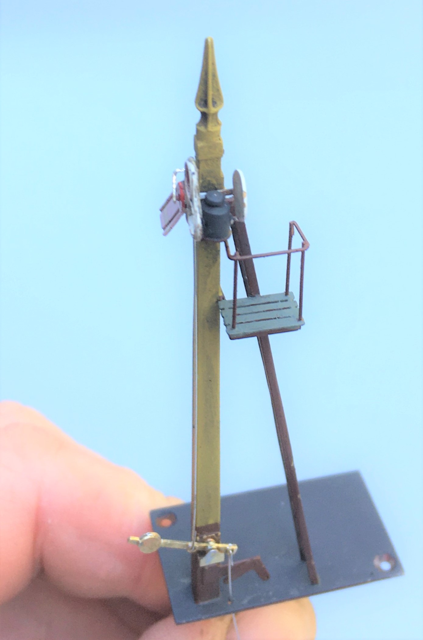
As can be seen, this still needs connecting to the servos and the touching in of the paint on the parts that I fit after the main assembly (the balance lever and the plate that wrapped around the signal arm).

Putting a Backbone into a Shed
The advantage of a railway company using standard building designs is that you can get to use them more than once. Thus Portchullin’s goods shed will be getting to have a new lease of life on Glenmutchkin.
I think my goods shed is the oldest model that I still have and over the years it is fair to say has suffered. Some of this is simply the thirty six shows that it has done with Portchullin (hell………thirty six shows…….!) and almost as many years, as I was about 17 when I made it. However the main issue was the manner in which I built it, with minimal bracing over the top of the entrances. This has lead to it breaking its back and despite several attempts at repair, these have never been long lasting. So it is time to do it properly to allow its reincarnation on Glenmutchkin.
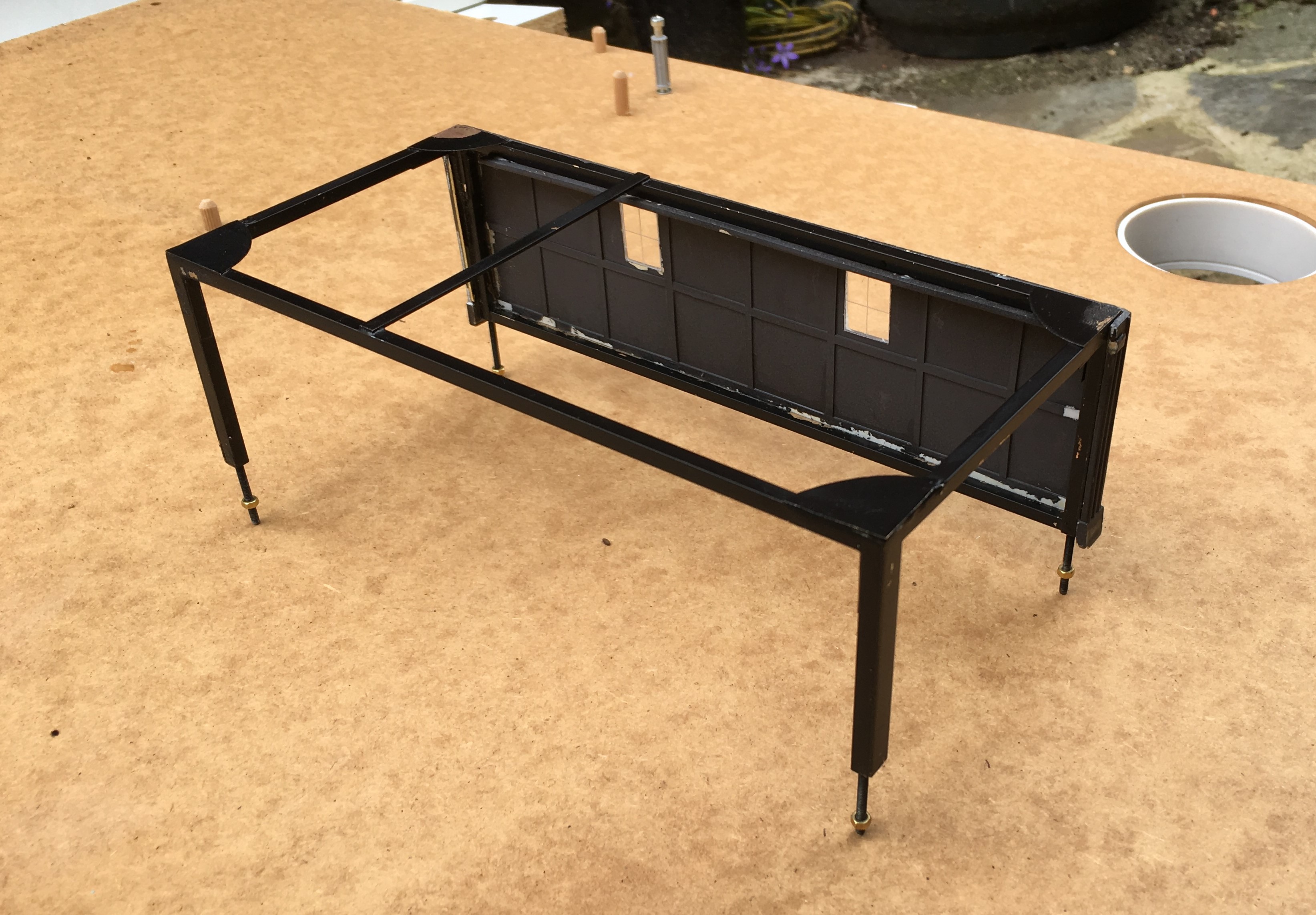
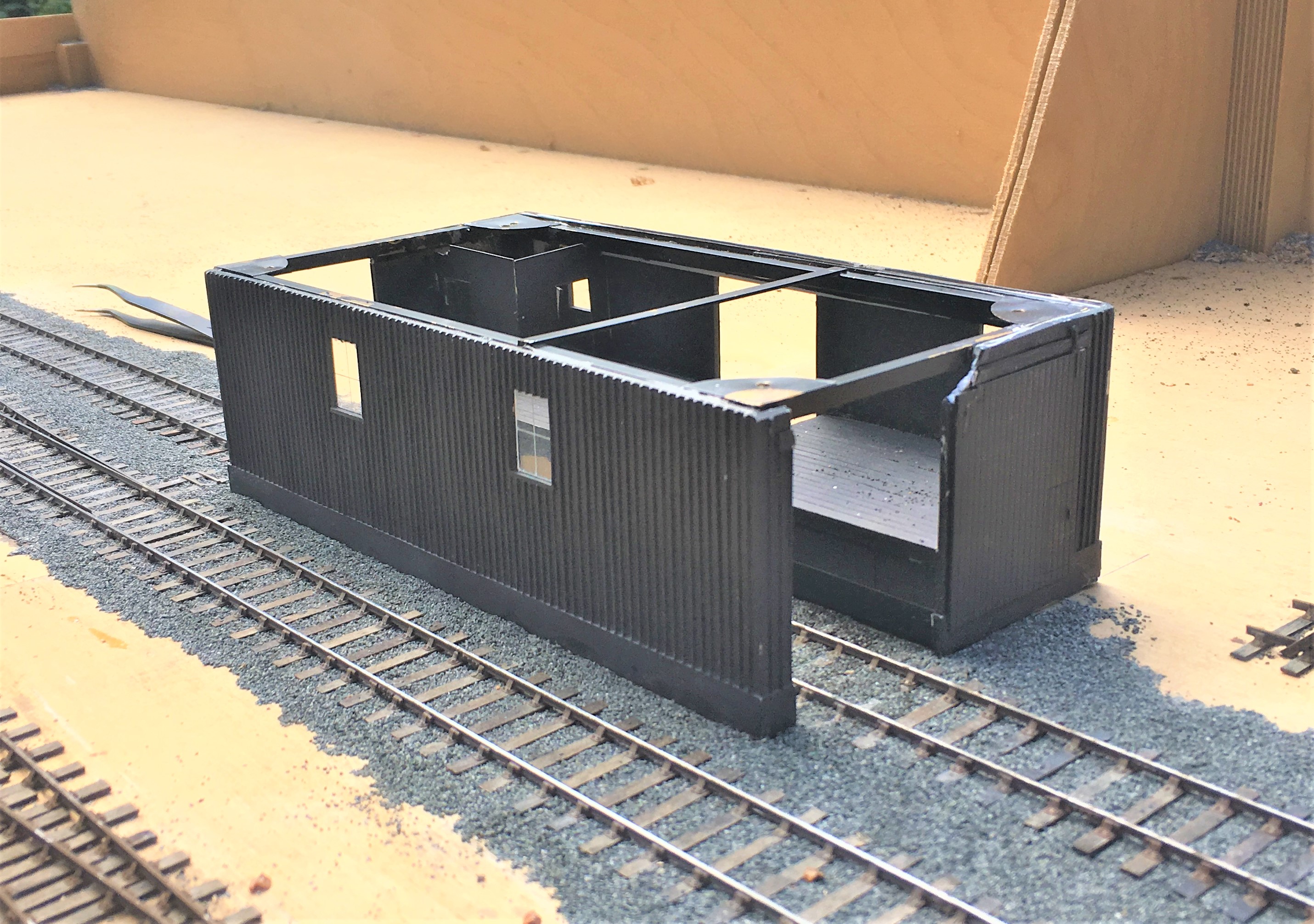
The key to the repair was to introduce a metal skeleton frame inside the model to strengthen it – particularly across the rail doors. This is something I now tend to do at the outset with any largish building I build to contain warping. The frame is invisible from the exterior – the view above shows the frame that I made with the first side attached.
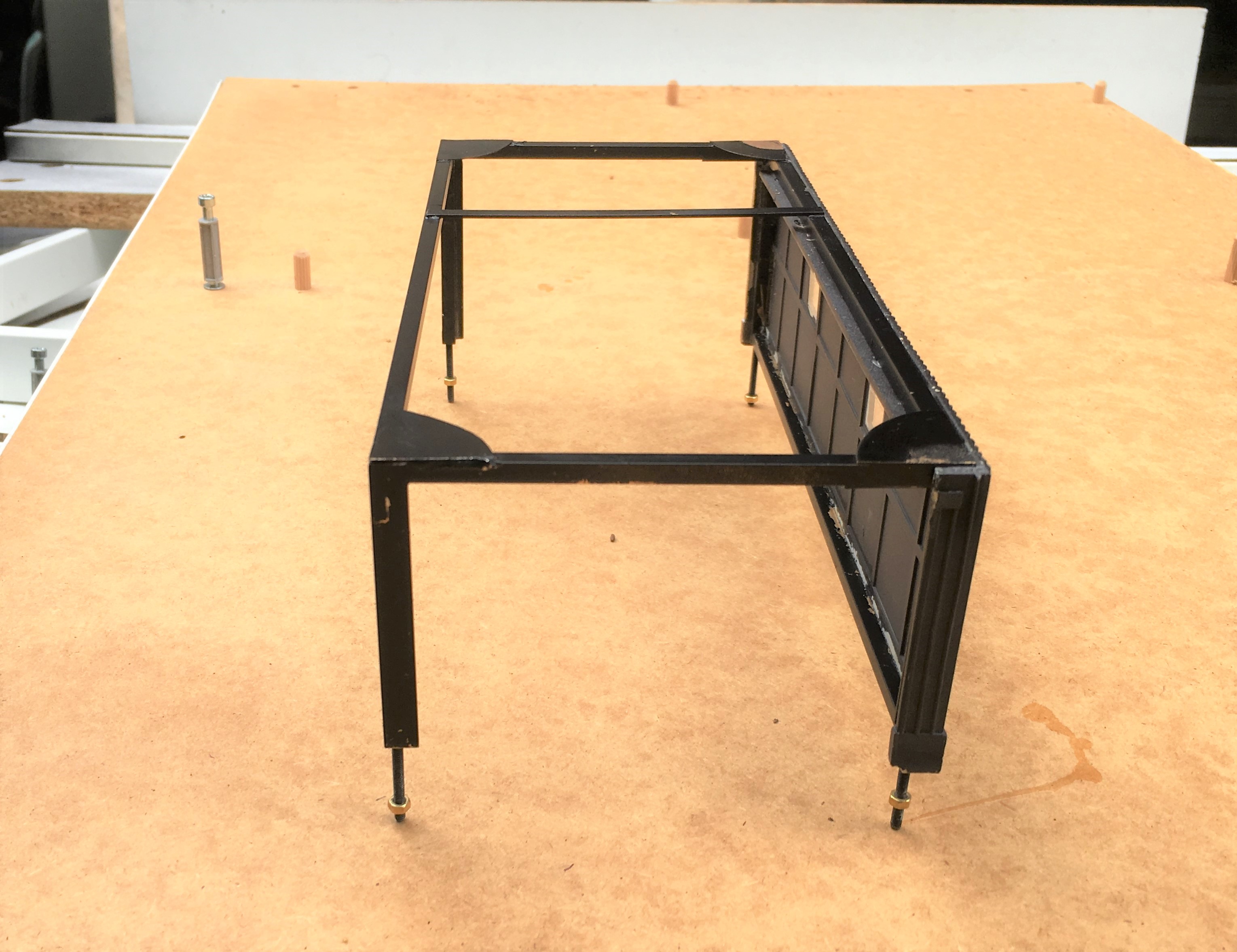
The frame was made with some 3mm square and oblong section brass, with gusset plates – there was a fair amount of metal so it got close to blacksmithing at one stage.
Once the frame was inserted, the model was given an overhaul to repair the other dinks and marks that it has acquired over the years. There were a fair few, as can be seen.
I also to the opportunity to install gutters and downpipes; something I had been meaning to do since I was 17………a bit of a shameful shortfall, given I am a chartered building surveyor!
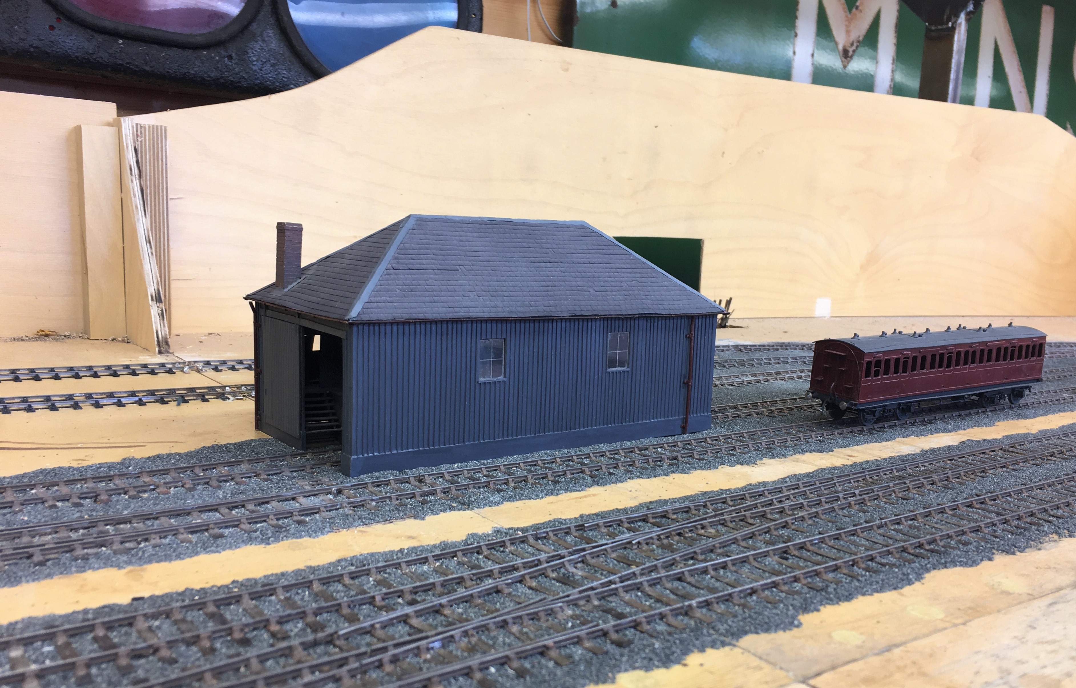
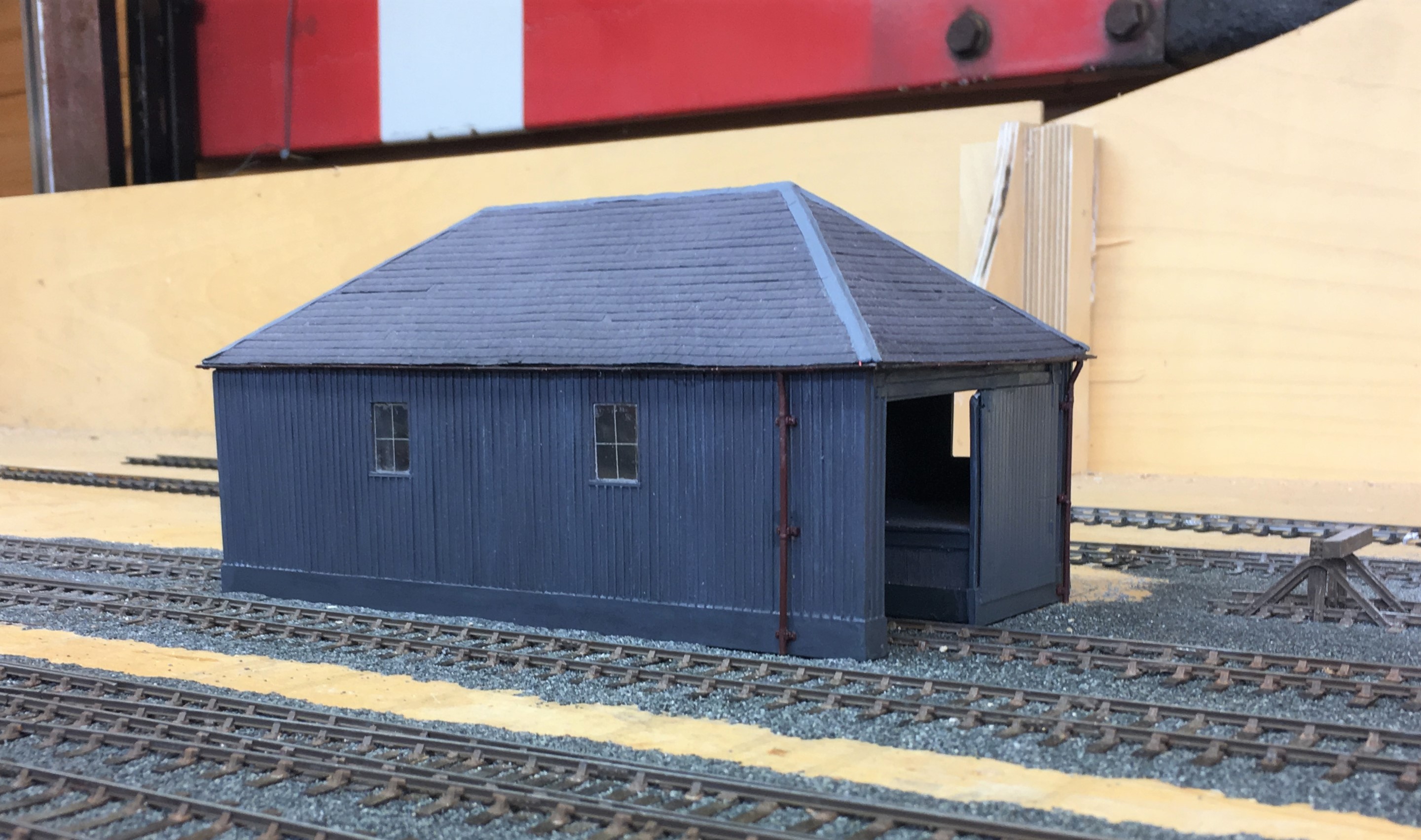
I am pleased with the results and the model is now much more robust so it should do at least another 36 shows! Whether its owner can will be kept under review!
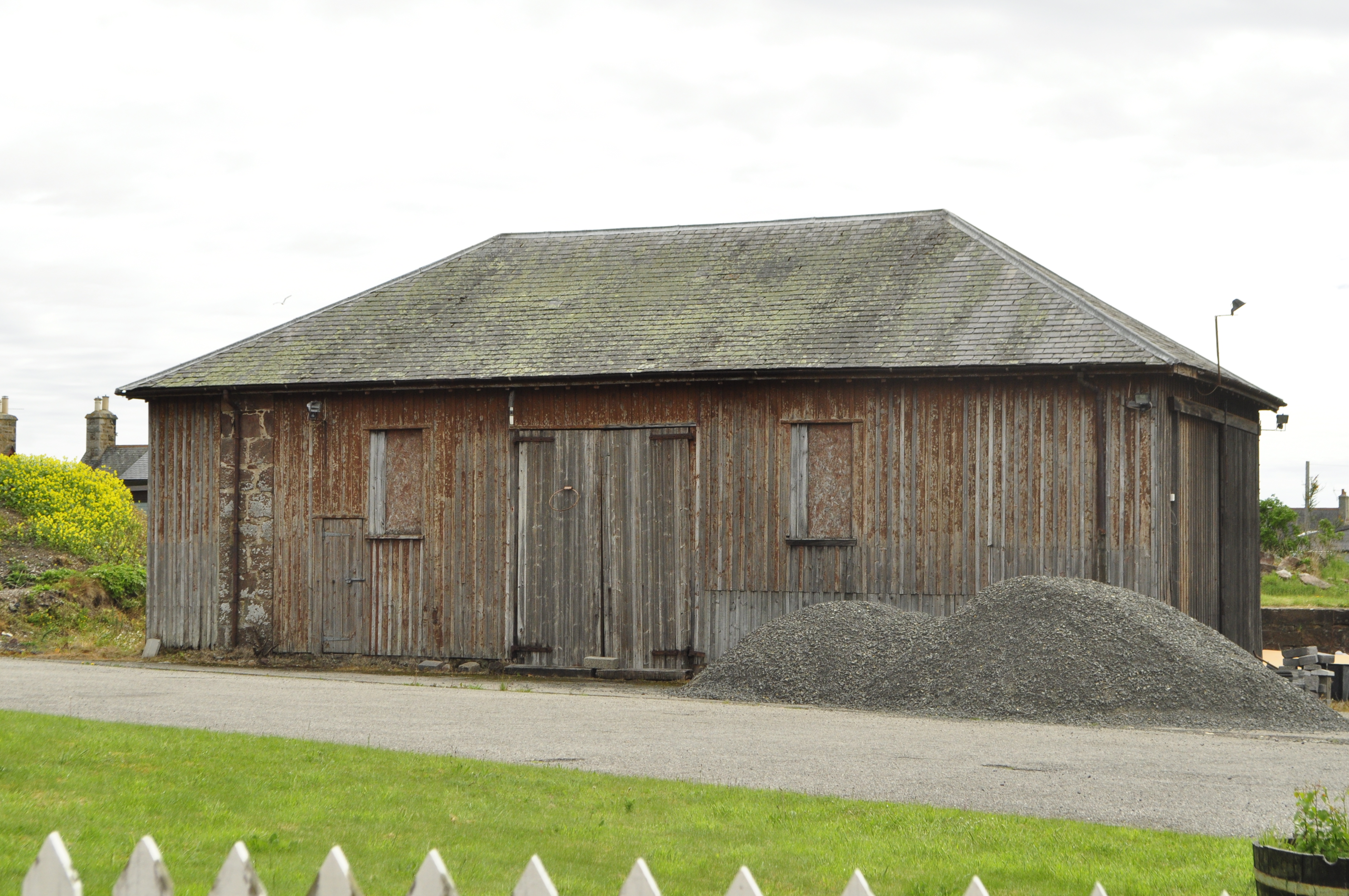
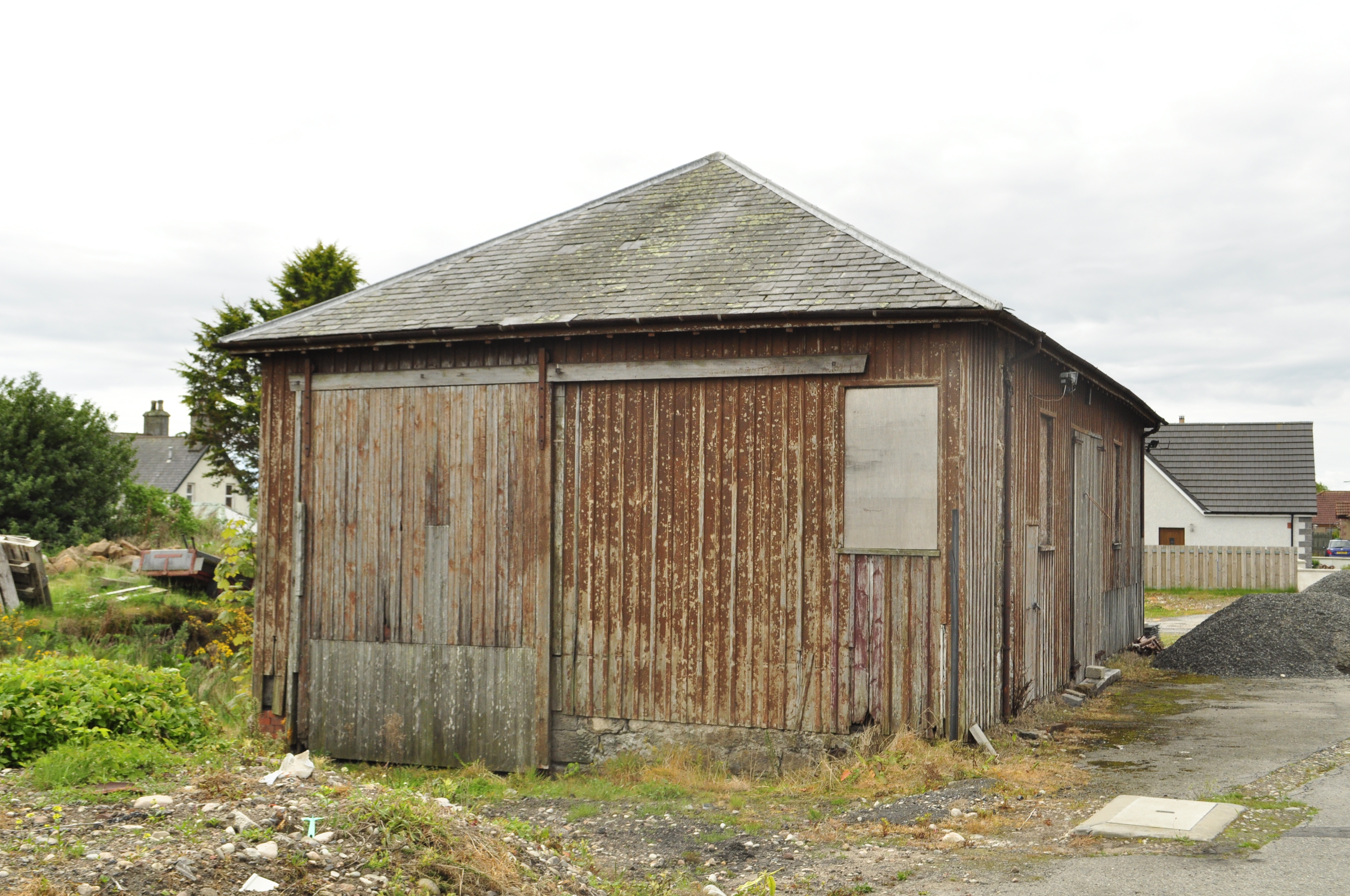
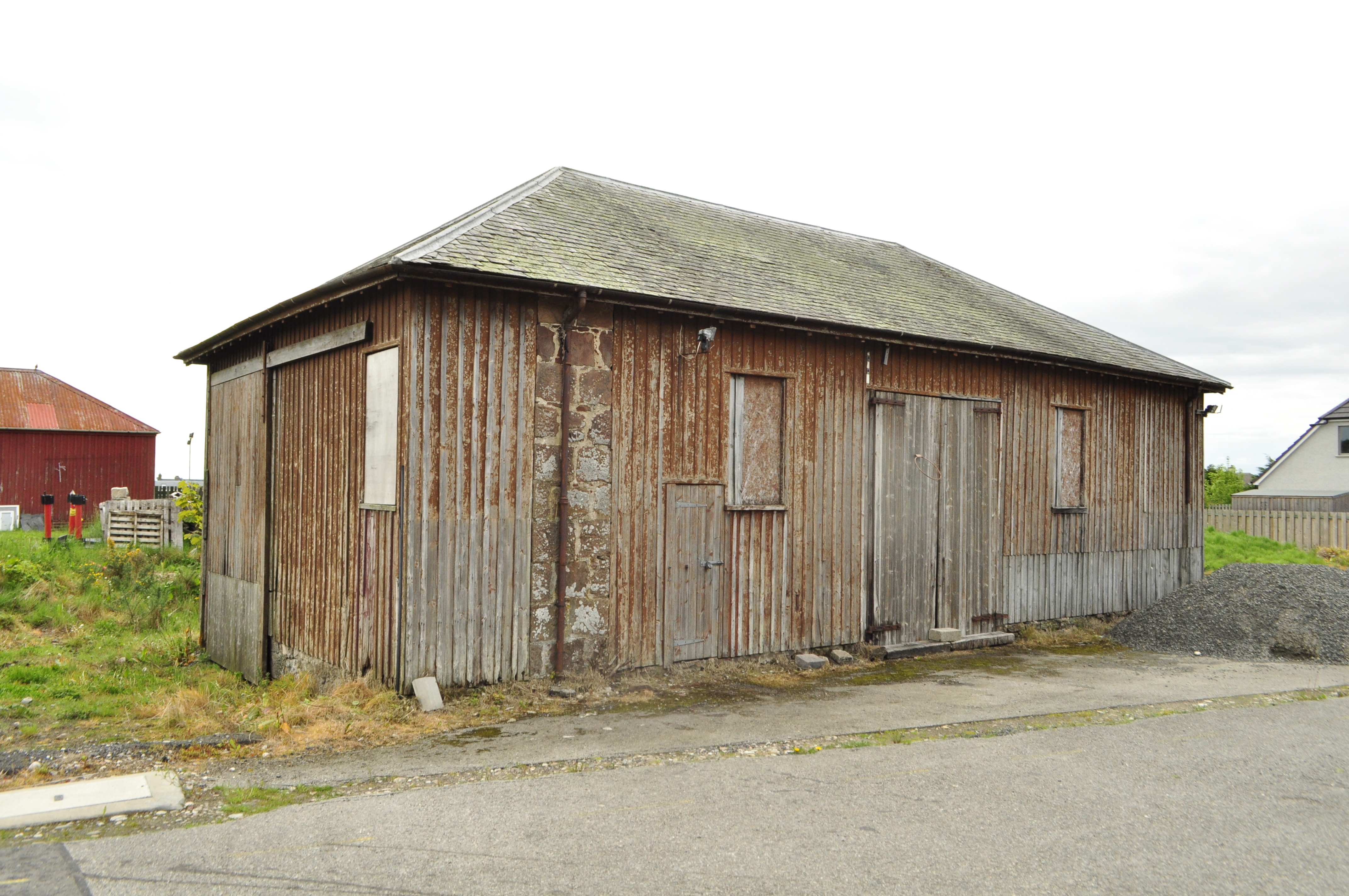
My goods shed is based on the Orbach drawings of the shed at Garve (the August 1952 edition of the Model Railway News). The prototype was swept away in the 1970s and whilst there are a pair of the smaller sheds still remaining (notably at Brora), there are no longer any of the standard Highland Goods sheds left. The last to go was in Golspie about two years ago and I did manage to both photograph and measure it before it went. Here are some views of it before it was demolished:
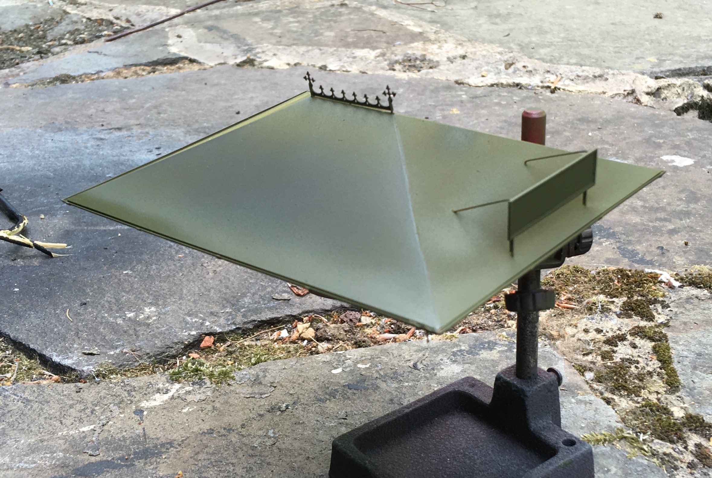
The Glenmutchkin Pharmacy – Part 2; Beware Roofers!
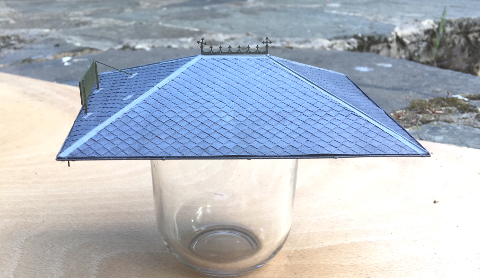
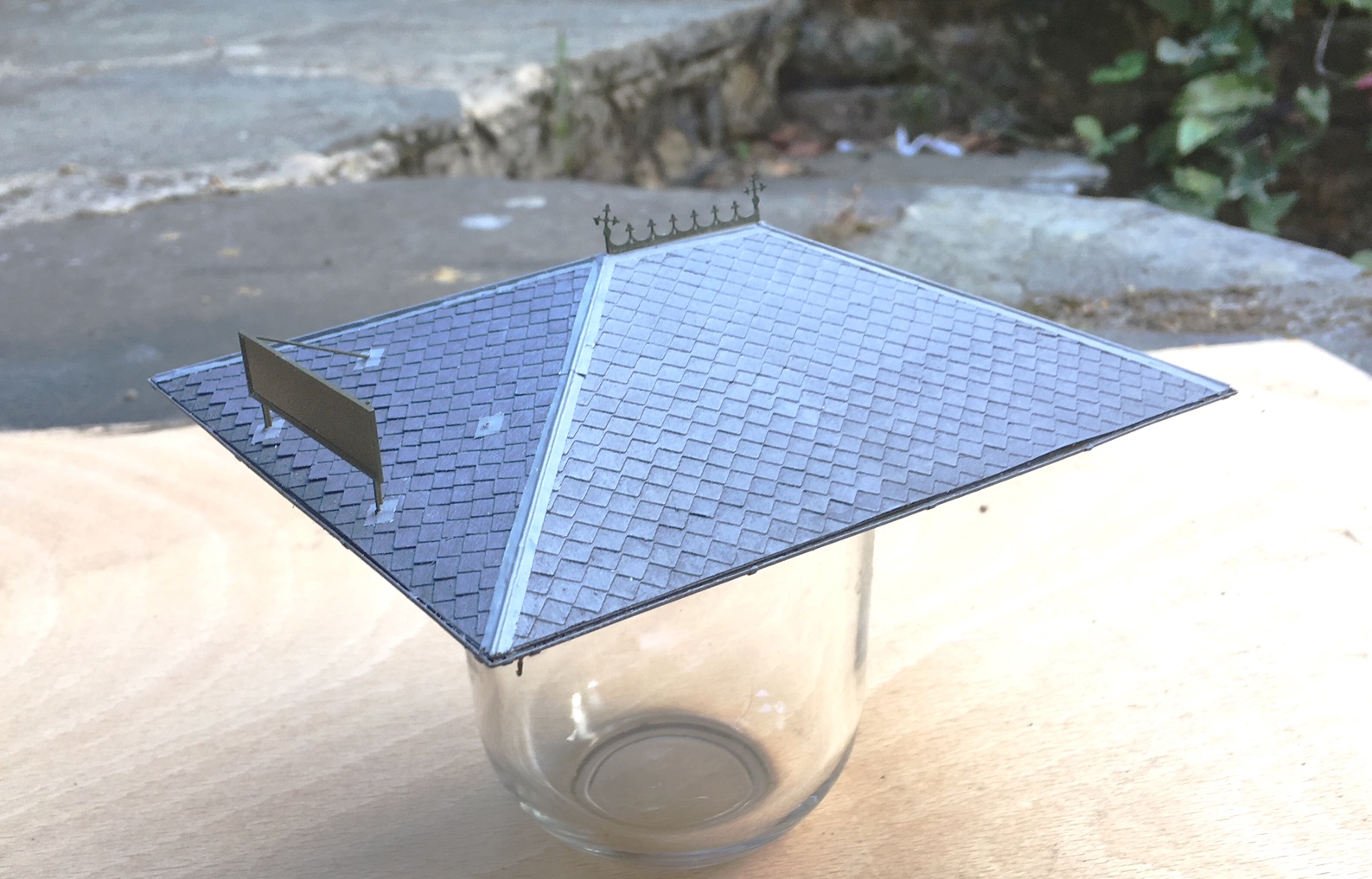
Progress with the Pharmacy building has continued and the roof is now nearing completion. I preferred using sheet metal (in this case nickle silver) for roofs as I find it is the easiest was to then include gutters. In this case, I designed the roof as a simple fold up etch and subsequently the gutters were formed by half round section from Eileen’s Emporium.
One of the pieces of artistic licence I went for relative to the real Kyle Pharmacy was to elongate the building slightly. This was partly because the prototype was a bit square and squat but also because I fancied including a decorative ridge piece. The Victorians and Edwardians did love a bit of decoration and this included the details to their buildings. There were numerous contemporary catalogues of architectural bits and pieces from which to choose from and I liked the idea of something pretty – especially given that this model will be right at the front of the layout. So I created a design of my own and etched it; along also with the characteristic sign that is so prominent in the photo in my last post.
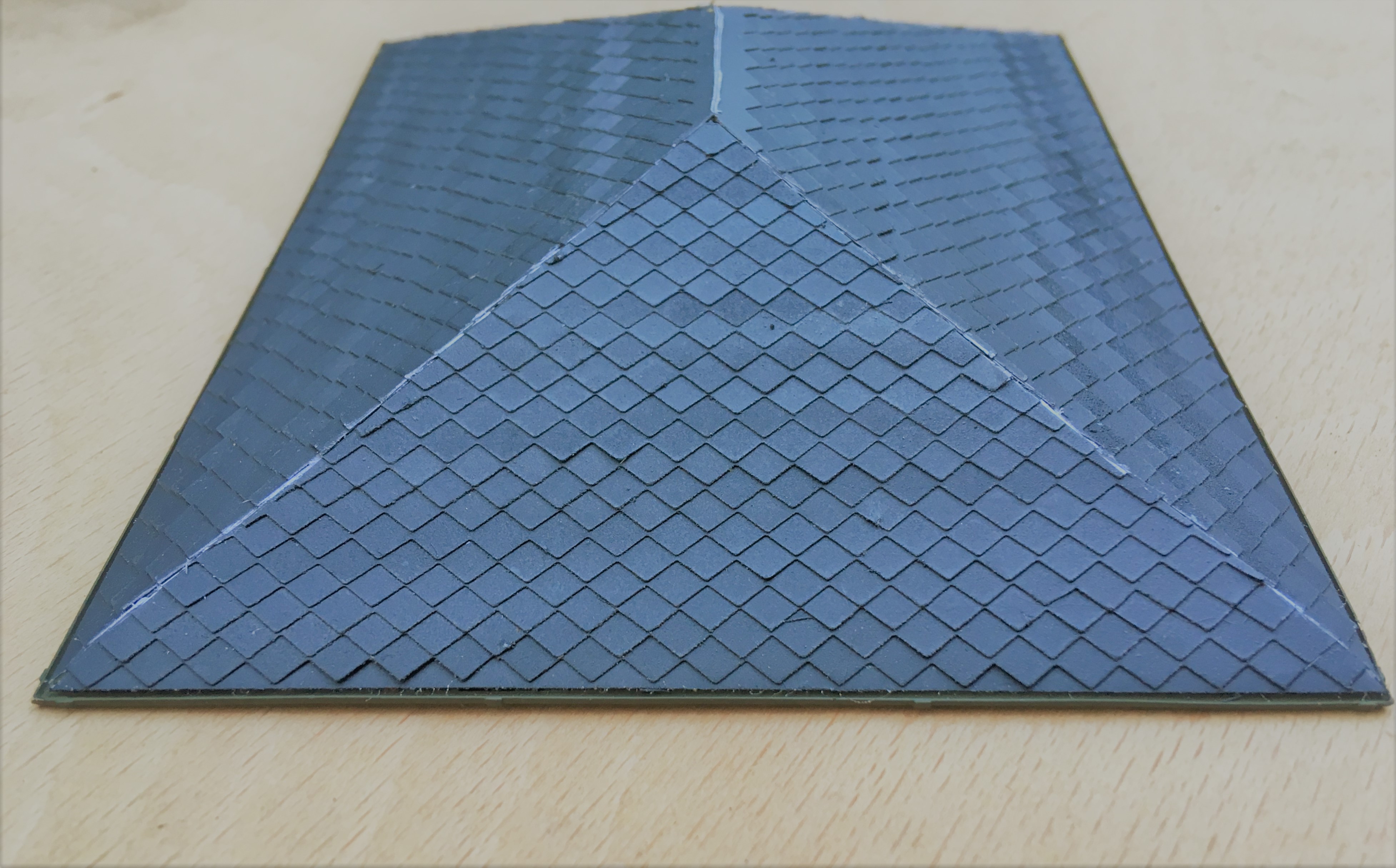
Those that looked carefully at the prototype photograph in the last post will have noted that the roof slates were diamond shaped. These were, in fact, asbestos slates and were quite a common material for pre-fabricated and simple buildings such as the Kyle Pharmacy. Clearly they needed to be modelled but I did no fancy my chances of cutting the odd couple of thousand slates consistently. I toyed with getting some laser cut or cut on a silhouette machine but then had a brainwave – pinking shears.
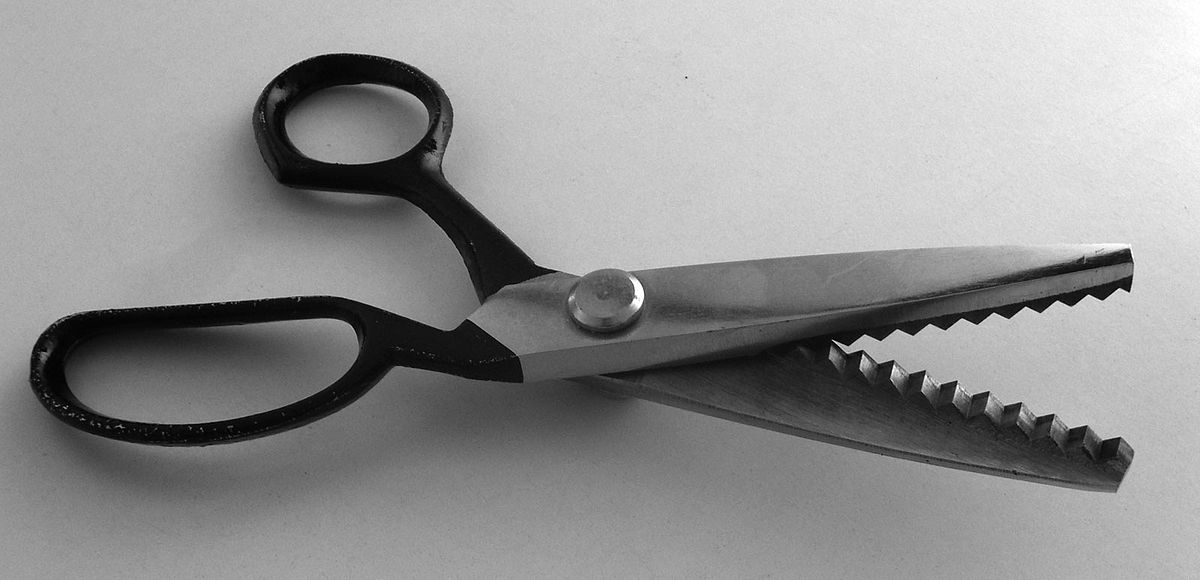
For reasons I don’t quite know, dressmakers use these to create zigzag cuts and even better, my wife had a set. However, she spotted me taking a look at them which meant I had a very firm talking too and was immediately banned from using them!! Researching them on the internet showed that they come in a variety of pitches but be warned not all of them have 90º serrations. I did find a set with a 4mm pitch which was a bit less than the 5mm that I thought was scale for the Kyle Pharmacy but as this equates to a 12 inch slate, I thought it was plausible and not a bodge too far. As you can see below, they produce a neat and consistent serration.
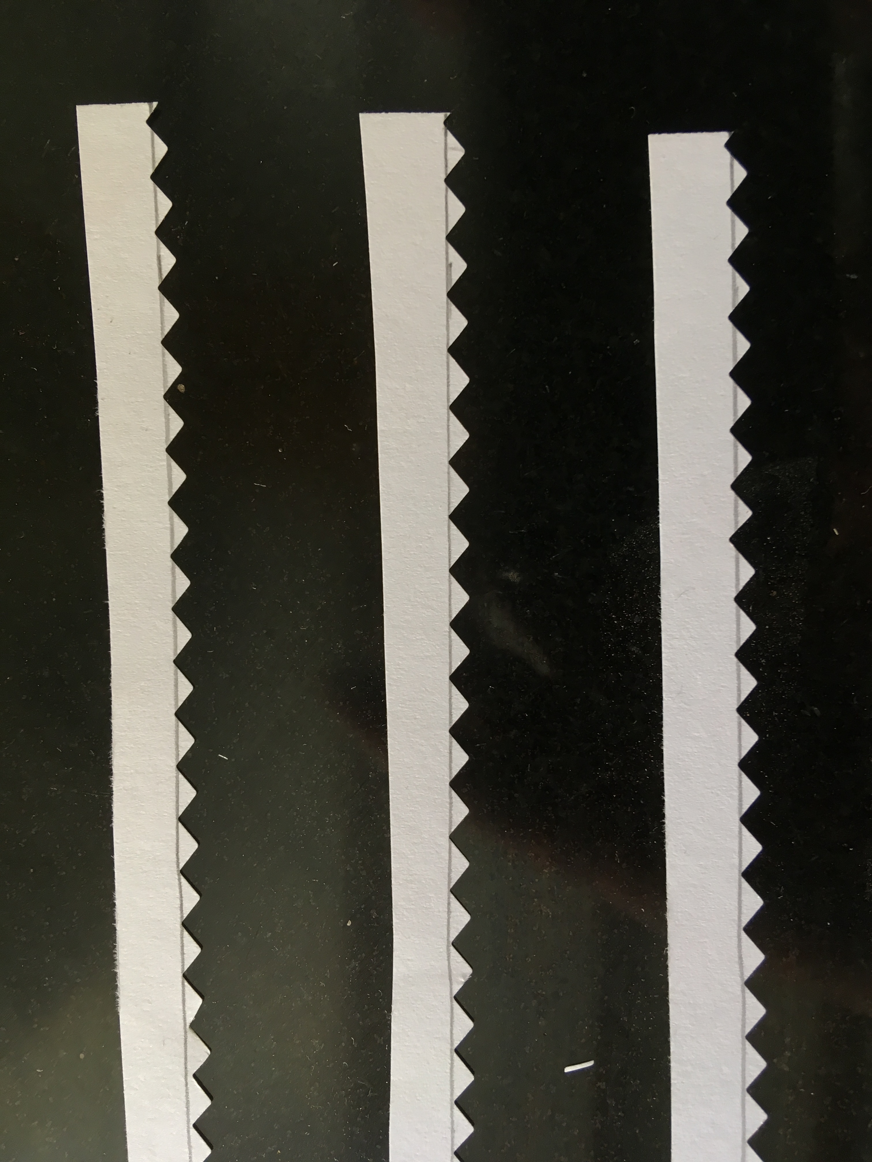
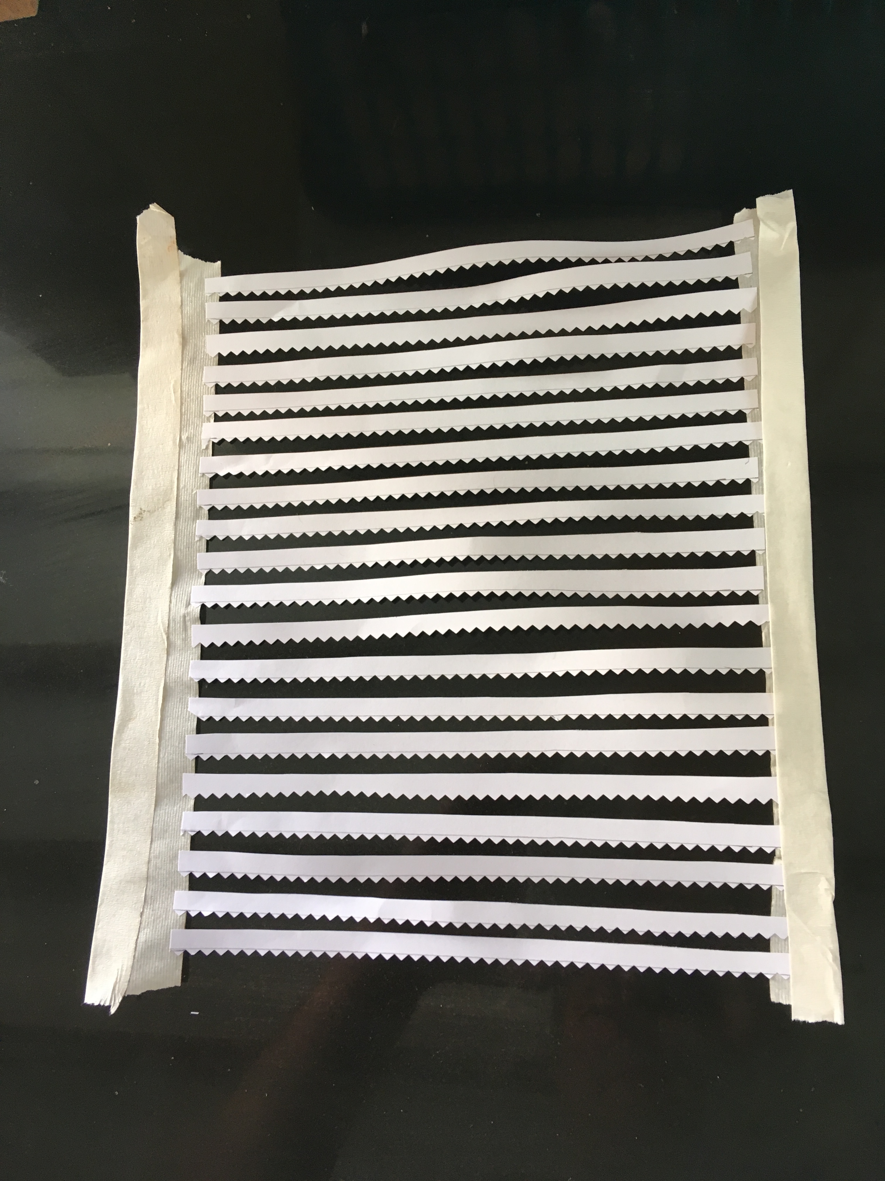
I cut the slates from plain paper in strips which I then sprayed a mid-grey colour because I felt that asbestos tiles might be a bit lighter than normal welsh slates. I deliberately allowed a tiny bit of inconsistency of colour to creep in, to provide a little texture to the roof. However, painting them was not easy as the air of the airbrush sent them flying – so I had to create a cradle to mount them in for spraying.
Once painted, I secured them with spraymount and carefully set them out, with the point of the diamond to the row above meeting the apex of the one below.
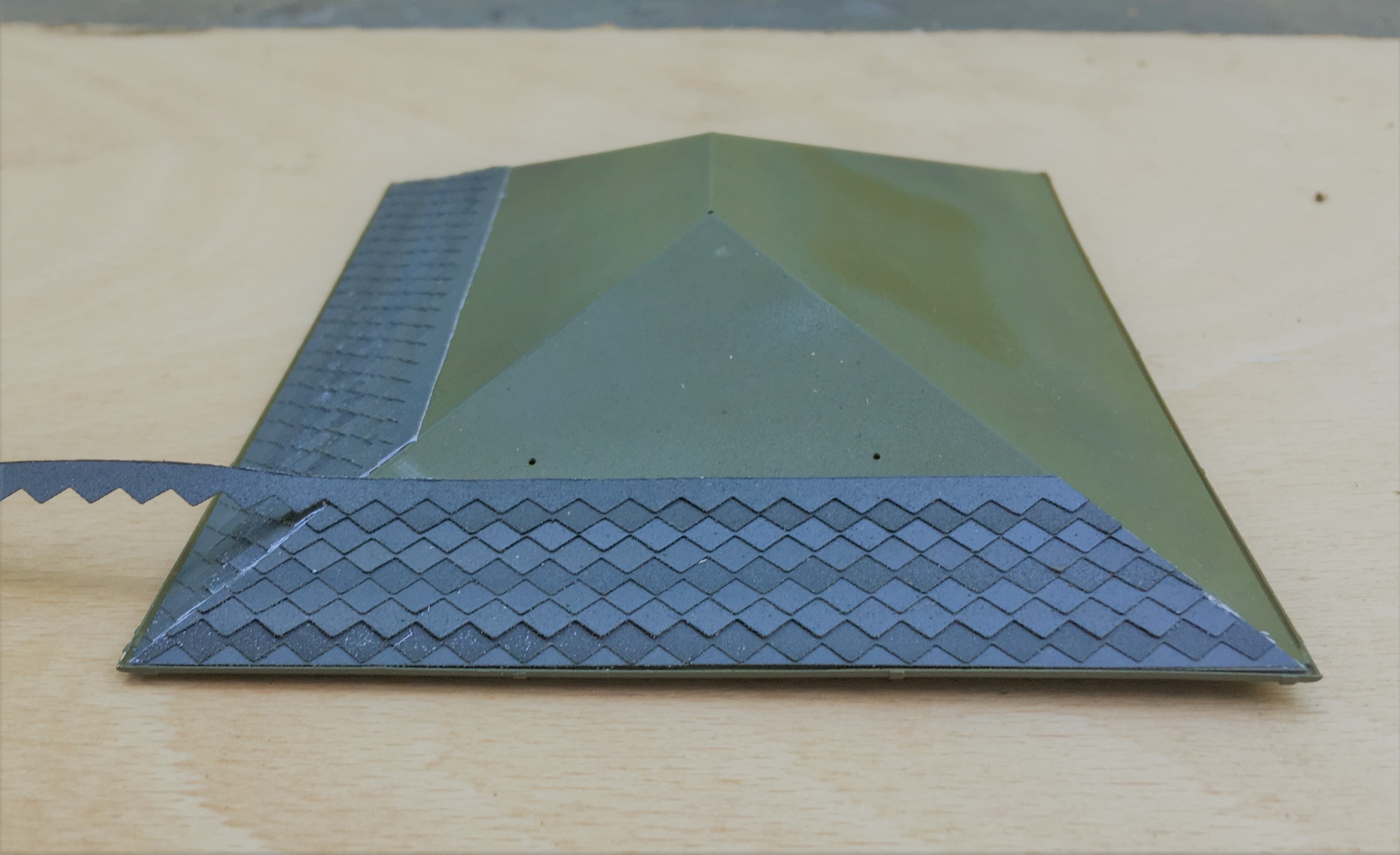
It takes some time (around 2 hours for a fairly small roof!) but I think the effect is quite convincing. I find the the best effect to make it look natural is to lay the slates as consistently as possible – you don’t achieve perfect consistency and these small imperfections end up making it that little bit more. Deliberately introducing inconsistencies tends to look a little contrived; including in this case my slightly differing shades, however, this was expected and can be overcome.
The blend the colours together, I washed the slates with artist’s acrylic always ensuring that the brush stroke was down the roof to mimic the flow of the weather.
I also formed the ridge and hip flashings with cigarette paper which I had first sprayed with grey primer and then secured with more spraymount. This was laid over 0.6mm brass rod to give the central lead roll effect – this was secured in place with superglue. I initially tried to make the lead flashings in sections so that the correct laps between one piece and the other was achieved but I never got close to a neat or believable finish. Thus I ended up doing this in one piece per run.
The front signboard will need some more work yet (partly because I have damaged it!), which will feature in a future post as I am going to have a bash at producing transfers.

New Shoes for Some Old Friends
Over the last few weeks, I have been revisiting a number of model coaches that I have built in the past, typically quite some time in the past as most of these have been around since either my teens or twentys!
Over the years techniques have changed and I undoubtedly would not build most of them in the manner that I originally built them if I was confronted with doing them again. Having said this, on the whole my handiwork – especially in respect of the painting and lining was really quite good. I seem to have lost my lining mojo in particular, so I am not sure I could line as well as this now. This is something that I really must get to grips with this, as I still have a lot to do!
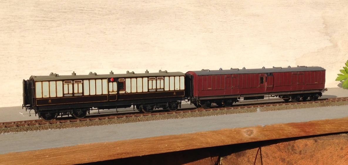
a pair of full brakes, the one to the left is a West Coast Joint Stock (from a London Road Models kit) and that to the right is straight LNWR (from a Microrail kit)
But the biggest area of difficulty with the coaches is that the bogies were generally formed around beam compensation units. These are OK for a couple of coaches behind a branch train but they impart far too much friction for a full main-line train as I aspire too. This is impossible to overcome whilst retaining the compensation units, the bar is the cause of the problem and it has to go!
To overcome this, Bill Bedford sprung boiges are being retro-fitting to all of my existing stock. These rely on separate hornblocks that secure a pin-point bearing in them – so rolling resistance is significantly reduced. The hornblocks are held in place by way of guitar wire and the effect is that they glide around the trackwork. They thus give the impression of weight and inertia that is much better than compensation (it is possible to get compensation that does not use the rocking beams that are the cause of the fritchion I am complaining about).
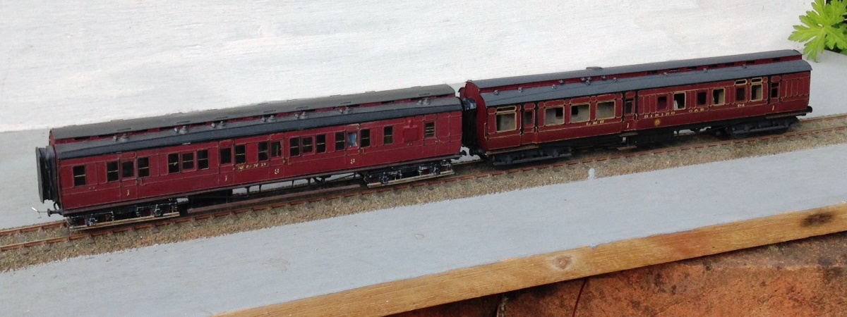
A Midland & North British luggage composite (from a PC Models kit) and a LMS (ex Midland) dining car (from a 5522 Models kit).
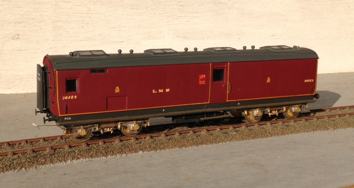
The Bill Bedford units are only an inner bogie and they still need to have some form of detailing on the outside. Some of these have entirely cosmetic outers, either of plastic or white metal but the two Midland coaches and the Highland TPO have something slightly different. On these, I utilised the original etched bogie sides and laminated them onto the Bill Bedford inners. This is very successful as it improves the Bill Bedfords notably by making them a lot stiffer and you get the crispness of the etching process.
This is one of my fathers, so I can’t claim credit for anything but the bogies. A Highland Railway TP (fully scratchbuilt). Obviously, no painting has as yet been done, so it does rather look like a ganster with gold teeth!
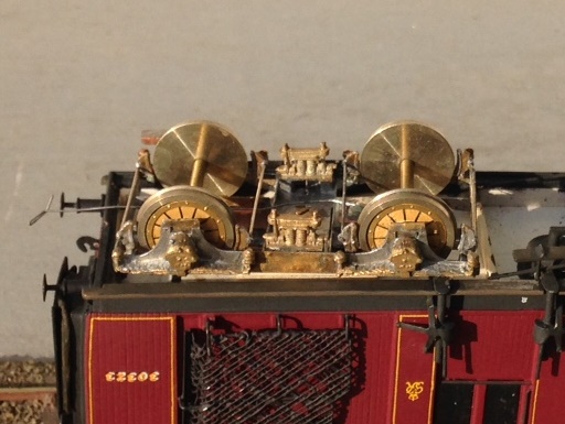
It is rather challenging to see how the Bed Bedford sprining unit sites inside the outer skins (from a Lochgorm kit) – so I will write up the process in a future blog – but this is what it looks like from the outside.
If, by the way you fancy some Fox Pressed Steel bogies that are neatly sprung and look the part – and almost all pre-group modellers ought to – keep watching the space. Subject to a test build or two, there will shortly be one available on the market.
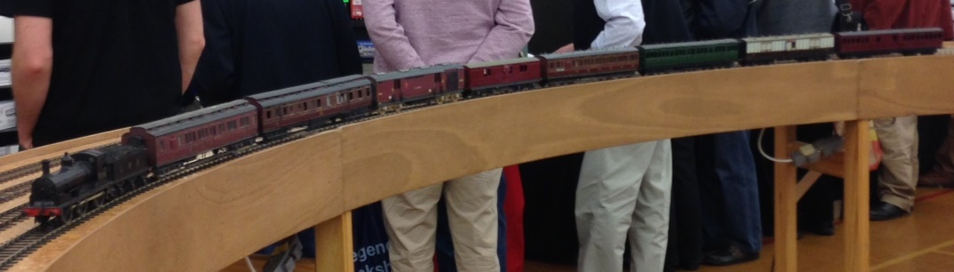
To test them, I took them and a few other coaches to ExpoEM to use their test track. Here we see a Barney with eight on – albeit a rather od mix for the train and there is a fair amount of painting and lining still to be done.
And to prove that they really do work and also to allow you to see how they glide, a quick youtube video: https://www.youtube.com/watch?v=6D7a_cWwGhg&feature=youtu.be
