Blog Archives

Princes Risborough North Box
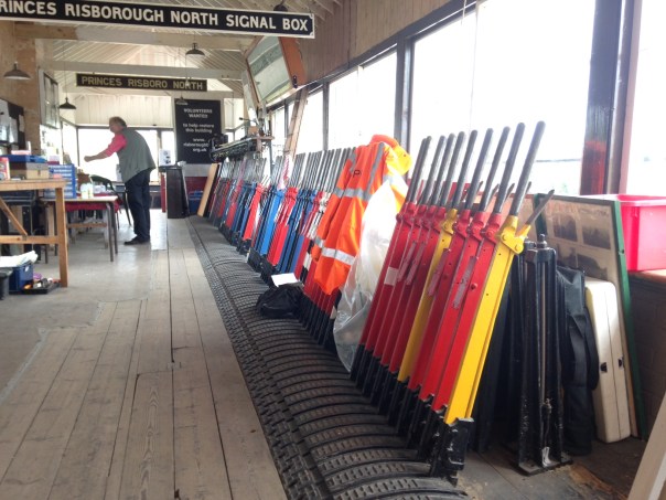
As part of the Missenden Railway Modellers summer retreat, I was lucky enough to be invited to see the Princes Risborough North Box, which is now in the custody of the Chinnor and Princes Risborough Railway Association.
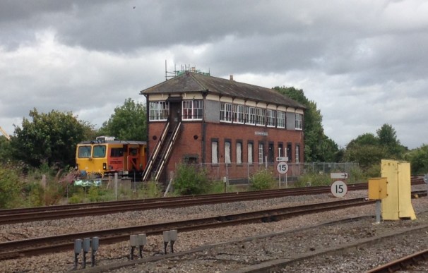
The box had lain derelict for many years, since its closure in 1991. Somewhat peculiarly, it was a break in by vandals during this period that potentially saved the box as it identified how seriously affected by water penetration and rot it was. This lead to the preservation society being able to convince Network Rail to let them in to stabilise it and they feel that had this not have occurred, when the building’s distress subsequently became apparent to Network Rail they would have merely ripped it down.
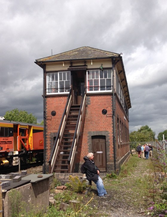
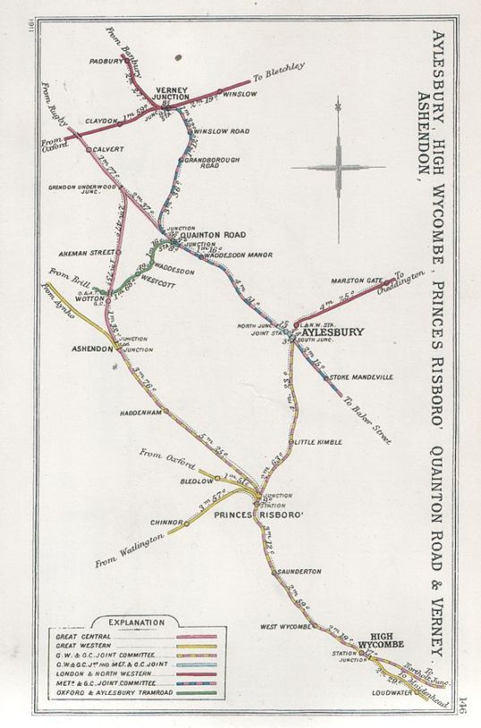
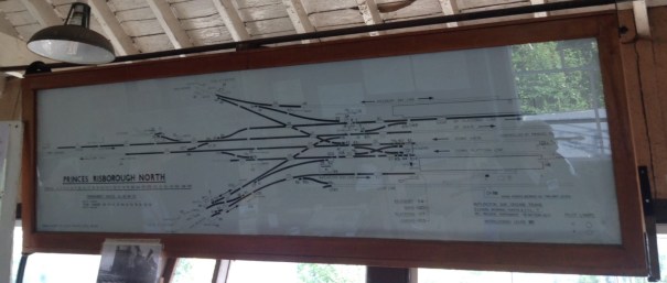
The box is substantial and is apparently the largest remaining GWR signal box in the country. It originally controlled the north end of Princes Risborough station but its size was determined by the complicated junction at this end of the station with three branch lines splitting from the main-line to Bicester and beyond. The branches it served were Aylesbury (still part of the national network), Oxford (closed in 1963) and Watlington (closed in 1957 but now reopened to Chinner as part of the preserved railway). The Railway Clearing House map is below and just to prove the complexity the box diagram too!
As would be imagined, there is a fairly extensive array of levers although in the various rationalisations that occurred through the GWR and BR eras have reduced the extent of these significantly. The preservation association have, however, reinstated many of the missing levers even though they are not yet connected to anything.
At present, the preservation society only have a temporary connection into the Princes Risborough bay platform but the intention will be to make this a permanent link onto their line, signalled via the box. However, given that this will still only be one of the lines that the box formerly served, there will only be a limited amount of it in use. Apparently the plan therefore will be to separate off the bulk of the box to create an interactive museum where visitors can play the part of a signalman.

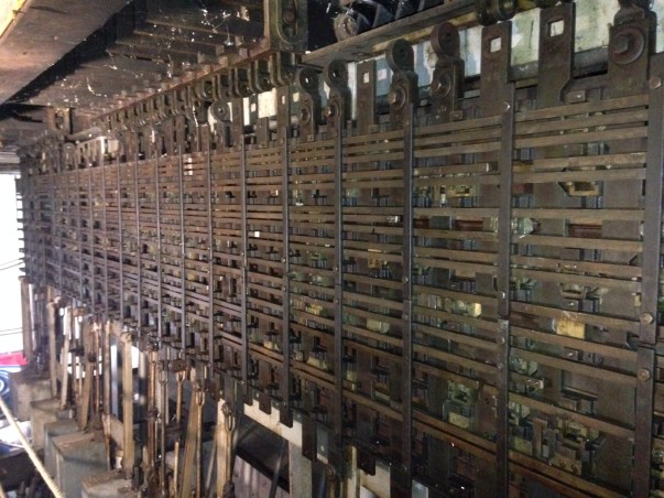
The treat for me (and many of the others on the visit) was to go into the frame room to take a look at the locking frame. Although I had seen this in model form before, I had never seen a full sized locking frame – even though this is only a shadow of its former self as it only covers that proportion of the box that was in use at 1991, it is still very complicated as you can see.
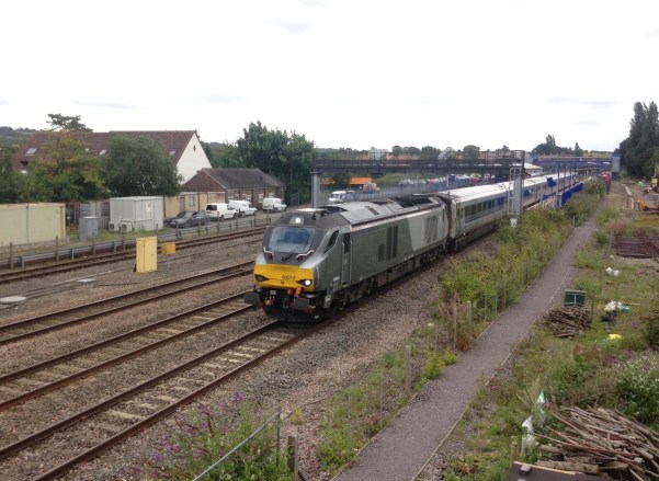
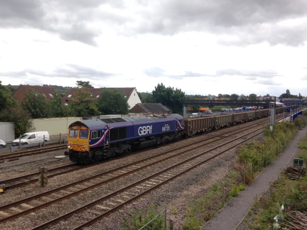
The Chiltern line is now really quite busy, far more so than when I used it to get to Solihull on business regularly. In addition to the procession of class 168 DMUs, there were class 68s on the trains for Birmingham and Wrexham plus a pair of trips each day with class 66s on spoil trains from the Thames Tideway sewer project.

And finally, this is what the box looked like in the days of steam. This photograph was taken in 1960 by Christopher Bomken when he was still in his shorts – it even won him 2 shillings and sixpence in a school photographic competition. Recognition at last Christopher it has made the interweb!
No, this is not the end. It is not even the beginning of the end. But it is, perhaps, the end of the beginning. Interlocked Lever Frame – Part 4
With thanks to someone else for the quote.
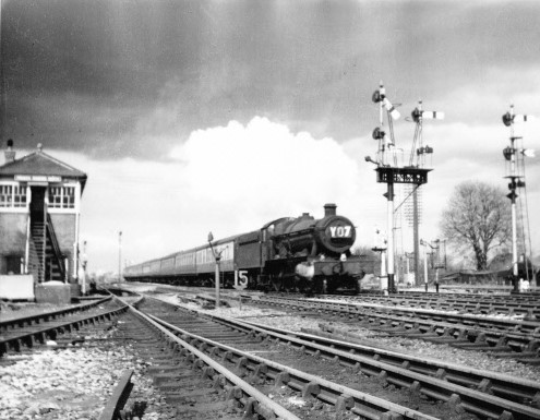
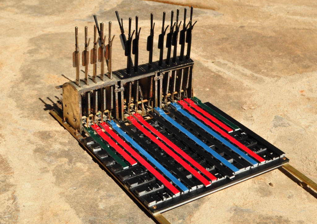
I managed to get all of the locking bars, installed over the weekend and the dogs (the teeth that engage in the sliding bars) to get the interlocking going. And this is what I get to:
This shows all of the components assembled in place. The dogs engage in slots in the sliding bars but the dogs have angled sides – so if nothing holds them in place the movement of the slider pushes them to one side and the slider can move. When another slider is in the way (ie there is an opposing lock set) then this can not occur – so it locks shut.
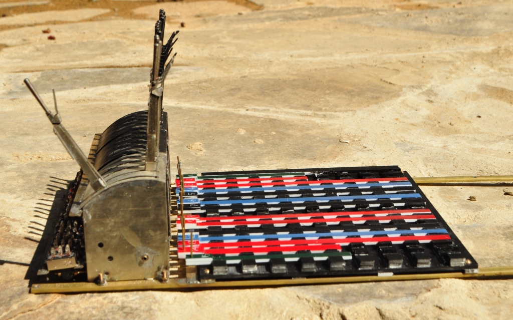
To stop the sliders popping up when they encounter a lock, a lid has been fashioned. I wanted all of the locking to remain visible, so this is just a skeleton.
I did find that the angles of the slots needed to be just over 45 degrees for the locking bar to move easily and they also need to match the dogs quite neatly. If I do this for real, I think some lost wax masters and then castings will be required to ease the process of manufacture.
The frame does lock well and neatly. Of course I made a few errors in where slots were to go but having made it from plastic, these were actually quite easy to sort out. What is more significant is that there is some slop in the levers – this occurs worst where the yoke of the bar that runs through to operate the toggle switch and sliding bars goes over the base of the lever. The hole in this is a bit too big and it means that the lever can move 30 % of its intended movement before it makes the sliding bar move and hence encounter the lock. This does slightly defeat the object of the locking and will need some work. I have an idea of linking the two more physically but if this does not work, then it may be back to the drawing board.
All in all, it works though and it is quite fun working through the desired move, working out what then needs to be thrown and in what order – although this may send my team a bit over the edge in the heat of an exhibition! However, some manufacturing refinement is going to be needed to make it work better. I remain tempted to use the potential kit that might be available but this makes the locking invisible and I am not so certain about this. Food for thought!
Interlocked Lever Frame – Part 3; the experiment continues
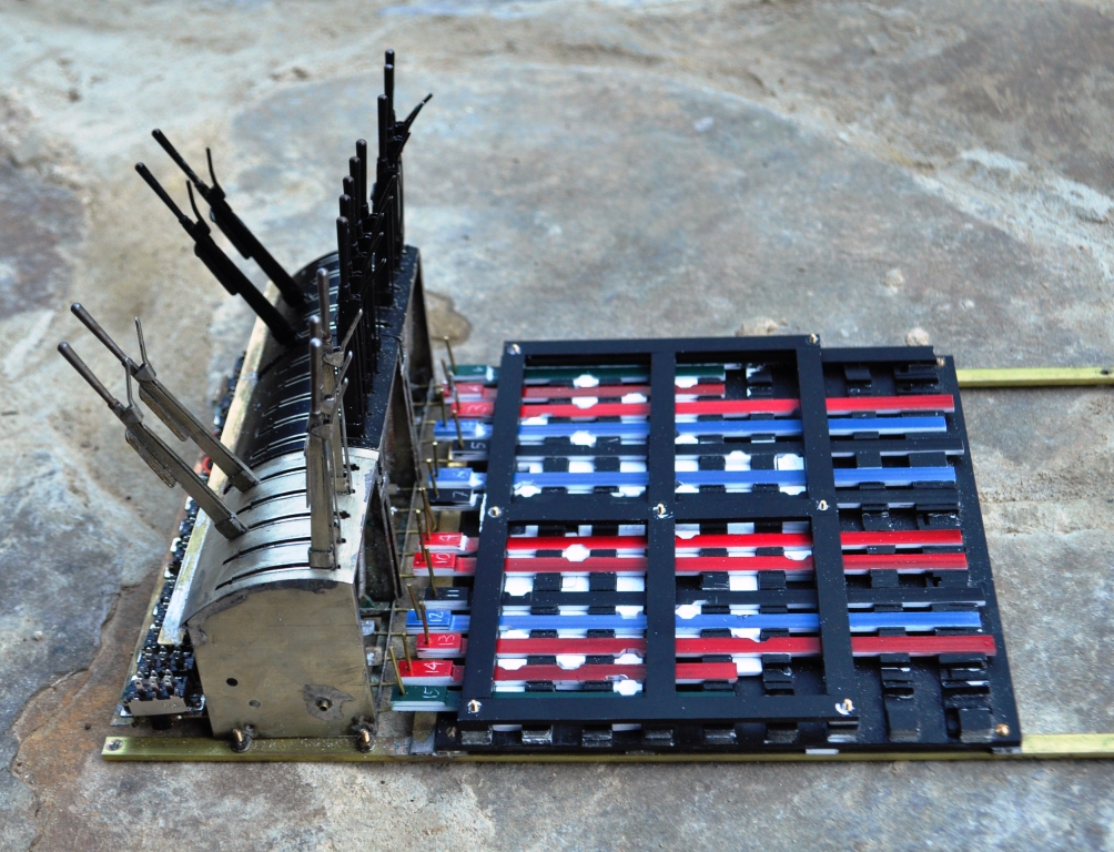
The saga continues and I have now made all the trays and the bars that the locks go into. As I have yet to colour the actual levers on the frame, I have coloured these to ease my understanding of things.
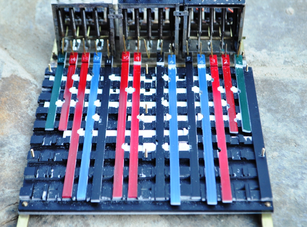
As this is an experiment, I am making this out of plasticard/evergreen strip to speed construction. The final thing will be in soldered and milled brass. I have yet to come up with a plate to secure all these bars in place, so they will not flop out as they presently appear that they might. This is what we currently looks like:
I have been warned that I may snap my tappets from the locking bars or something else. This is due to the significant mechanical advantage that the lever has over the through of the bar – if you look at the end view you can see that it is about 10:1, so I can see why I am being warned. Ultimately this is an experiment so I will take it easy with the frame if it breaks I will know that it will need to be tougher next time!
Interlocked Lever Frame – Part 2; More Experimentation……
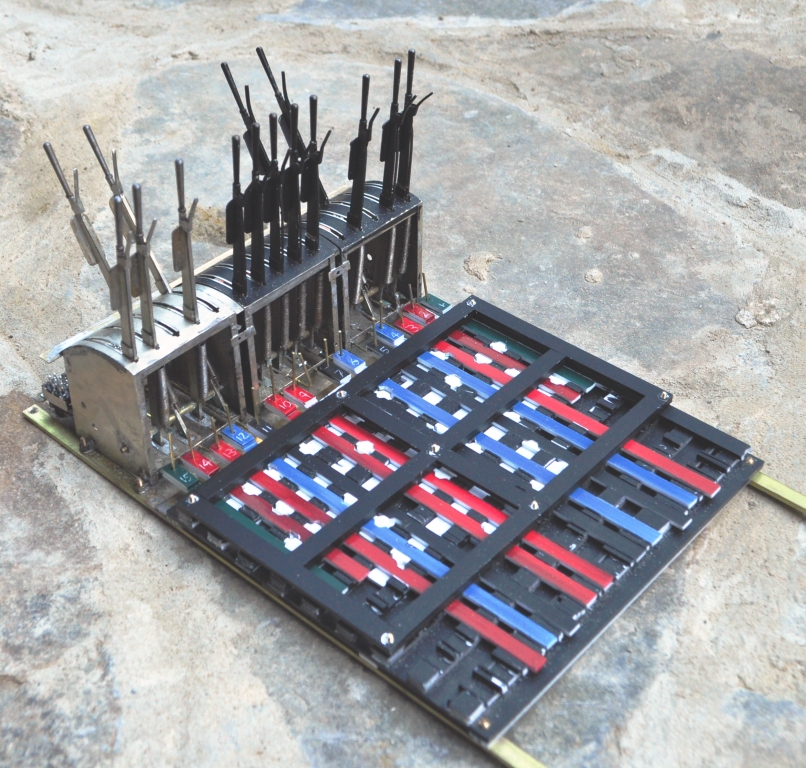
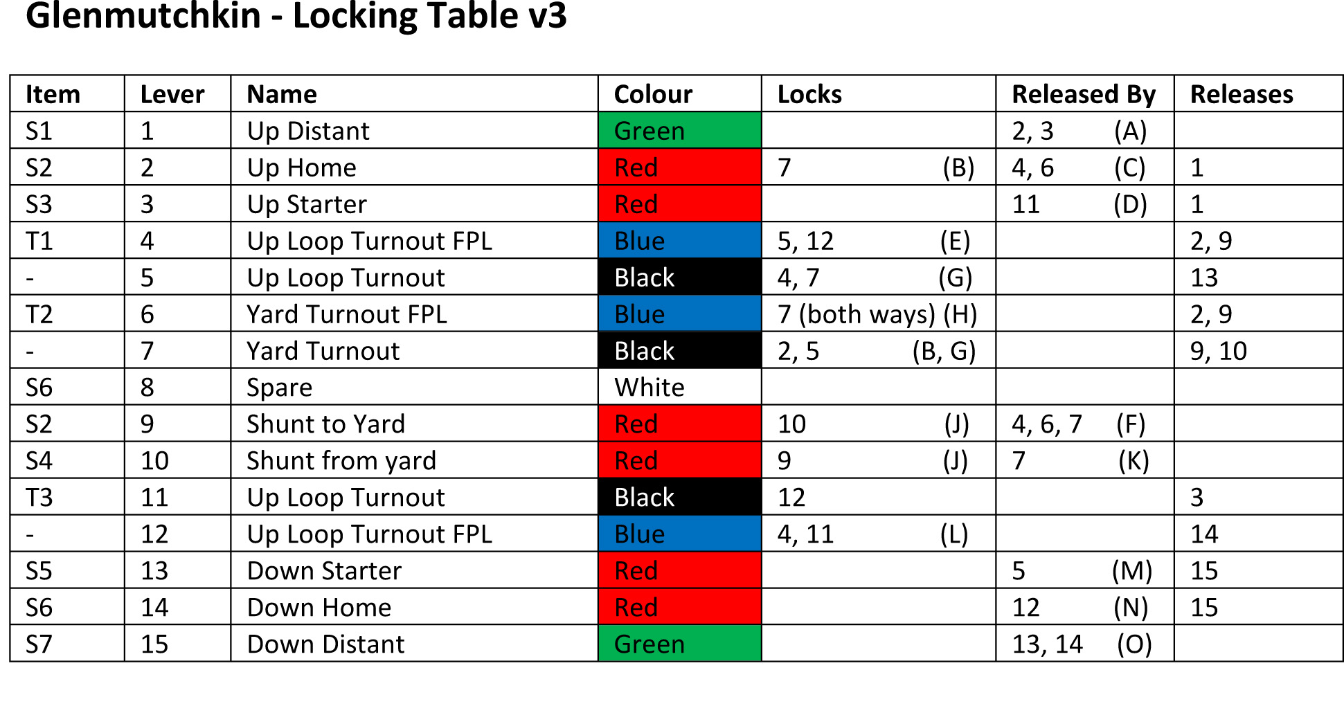
With a lot of help from Keith Norgrove (thanks Keith) the locking design for the lever frame should now be concluded. This is where we are at:
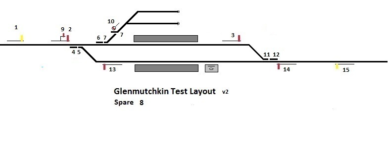
 The lever frame is also ready to receive the beginnings of the locking frame; so guess what i am doing this weekend………..
