Blog Archives

Diagram 51 Full Brakes – Test Build part 5; now in glorious technicolor!
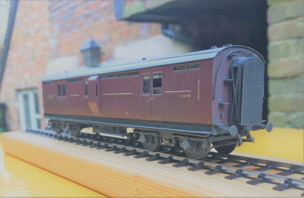
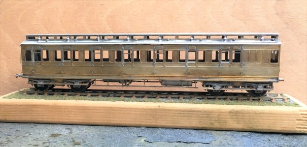
The pages of this blog have charted the development of a proposed kit to build the Highland Railways dia 51 full brake; well finally it is finished and we get to see them in the flesh and painted up.
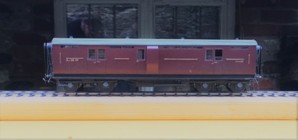
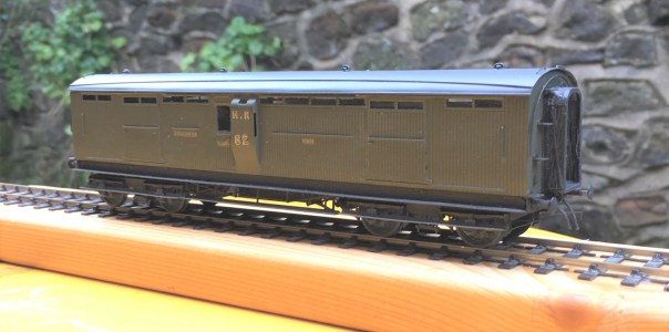
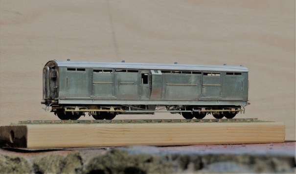
The kit can produce, with a bit of modification, two variants of door and I have now build both of them. First up the cupboard door version painted in crimson lake and minus full footboards.
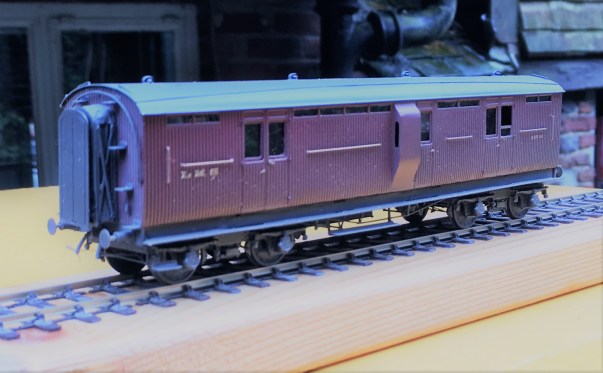
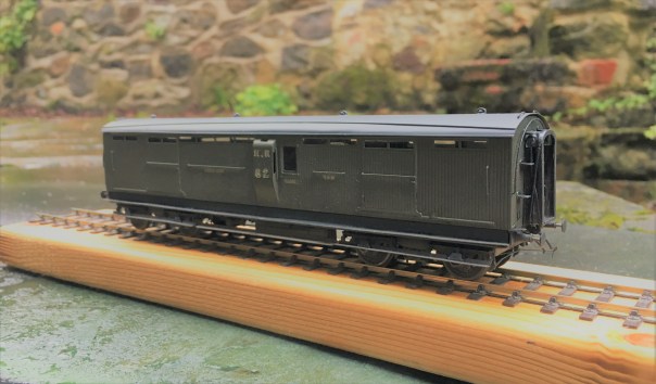
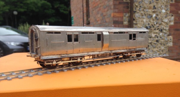
Second we have the sliding door version, this being modelled with full step boards and in Highland Olive green.
Apologies that the technicolor photos are a bit short on gloriousness; it is fair p*ssing down today and this is the most light that I could get to take any photos!
If you want to recap on the earlier blogs that show the development of the proposed kit, you can find them here:
Part 1 – getting underway with the body
Part 2 – drawing the chassis and roof to a conclusion
Part 3 – the build of the second vehicle (sliding door version)
Part 4 – details of the spring bogies that accompany these (and many other coaches)
I do now have a batch of these back from the etchers and I aim to conclude the instructions on Monday/Tuesday. I will then make a notification that they are available but at present I cannot provide the castings and those to the bogie are rather important. If you can scavenge from a Lochgorm kit some Iracier axleboes/springs, you will be able to complete the kit; if not then I am seeking to either source some of these castings or produce my own. So watch this space.

One for the Paintshop
I am sure I am not alone in having in mind a list of modelling jobs to do over the Christmas break and to find that the bulk of the list remains uncompleted when it is time to go back to work!!
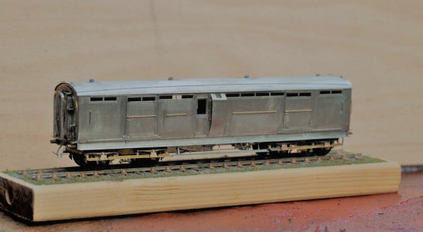
One item on my list was to finish a North Eastern Railway autocoach that I have had underway for a while and that at least has got itself off the list!
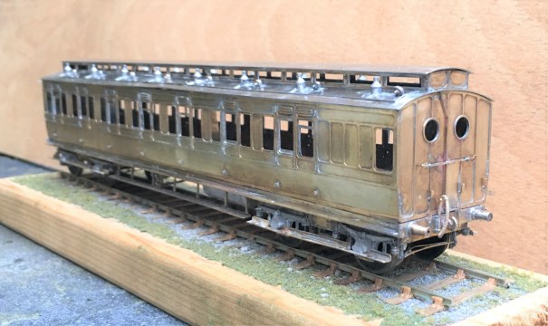
The bulk of this is from a D&S etched kit which I have seriously devalued by opening the box!! I have replaced the fixed bogies with some test build sprung bogies that I have had under development for rather too long now (they are finished, but for the castings which I need now to produce following the demise of Lochgorm Models for at least the time being).
I also replaced the roof with some metal sheet rolled to the curves. This proved a real challenge and took more than one attempt as I found you could not roll the section with the holes for the clerestory already cut as the bend all occurred at this weakened point. I also took the effort to put on the gas lines with fine wire as I think these add so much to a model of this era.
I think they are very attractive coaches but there is a problem with them – they tended to go in pairs so I have another to build! Just not quite yet! Fortunately, the BPT is not down to me, but I think you may find yourself under pressure soon John!!!!

Dia 51 Test Build – Fox Heavyweight Bogies
After the painting disaster, I have been working on the latest version of the Fox Bogies. The prototype utilised a patented design with pressed steel plates to form the sides and ends which produced a stiff and resilient frame, better than the other contemporary options. Thus these bogies were very common amongst the pre-grouping companies with most of using them to at least some degree.
Although there are several model manufacturers that produce Fox bogies, there are no versions that use springing which I now prefer. As they were the primary form of bogie used by the Highland Railway, I need a few of them and thus I have been putting some effort into getting a top notch solution. In this regard, I have been assisted greatly by Justin Newitt if Rumney Models whose design of sprung bogie has formed the basis of this.
The model has primary suspension on the pin points based on guitar wire springs,
In addition to this, the design has a sprung bolster, also based on a guitar string suspension.

The castings I have used on these are from Lochgorm Models and the design has been conceived to enable these to be used either retaining their dampers (the cylindrical appendage at the end of the leaf springs) or with replacements that are a little more defined.
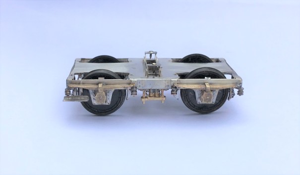
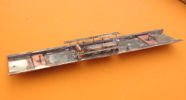
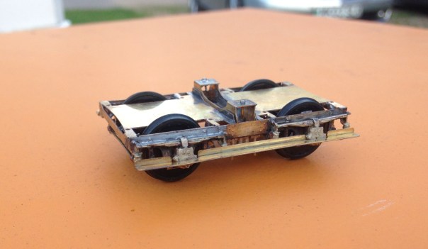
The etch is also designed to be provided with full stepboards as below or with only a short section to one end – as they typically were converted to during their life.
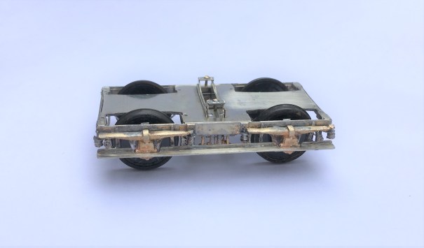
There is full brake gear provided, with a little trick where they do not pass under the axle (remember this view is upside down!) – this enables the wheel to be removed if this is required.
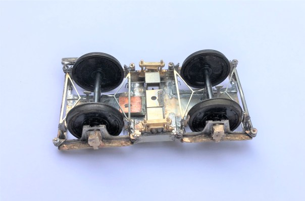
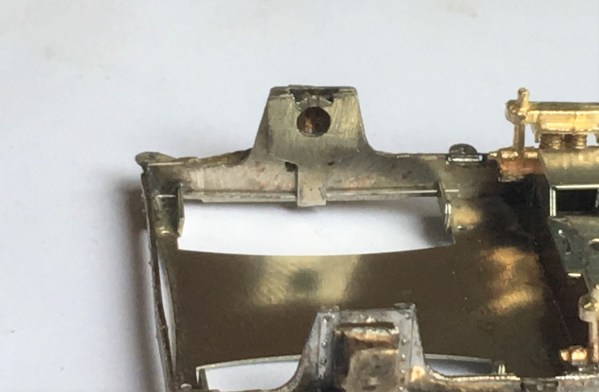
This is not the first version of these (don’t accuse me of not test building my designs!) and they are very close to done. The final change is to adjust the primary spring hangers slightly so that they are not visible when they are depressed (you can just see it poking above the sides in line with the axlebox), The advantage of computer drawn artwork is that things like this can be changed relatively easily.
These, and indeed the rest of the dia 51 full brake, will be made available for sale quite soon.
Previous parts to the test build can be found here:
- part 1 – the main body shell of the cupboard door version
- part 2 – the underframe
- part 3 – the second one, the sliding door version

Dia 51 Test Build Part 3 – and then there were two…..!
Following the first test build of the dia 51, I took account of what I had learnt from this and completed various amendments to the artwork. There was nothing truly major, so I was fairly confident that the corrections would get the model to the point where the artwork was done. But of course, to prove this, another test build was required and this is where we got to………..
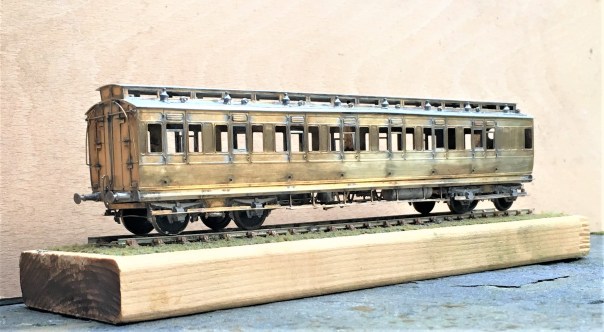
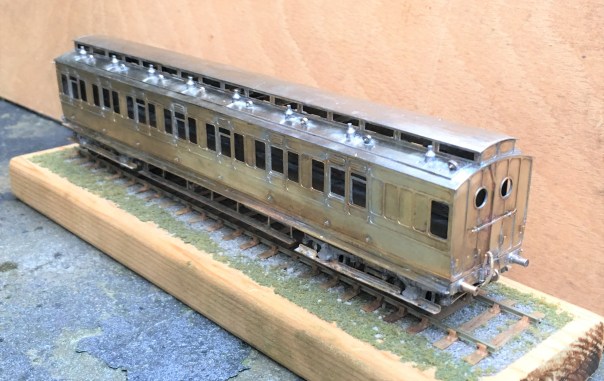
And this is what it looks like……..quite handsom I think and certainly quite differnt from all the pother stock I presently have.
The eagle eyed will spot that the vehicle is slightly different in that this one has sliding doors, whereas the previous had cupboard doors. The kit is intended to cover both options and does successfully do so.
The ducket also has cut outs for a lamp at its head (a feature of Highland duckets). This proved quite challenging to model and I will avoid doing it again because it seemed to fall out of favour prior to the end of the Highland era so having only one or two would be right for my timeframe.
There remains a bit more work on the bogie to do; they can be made up to work very well but are a little more difficult to build than I had hoped. Once this is cracked, I will be making the dia 51 available for sale.

Dia 51 Test Build – Part 2: Nearly There
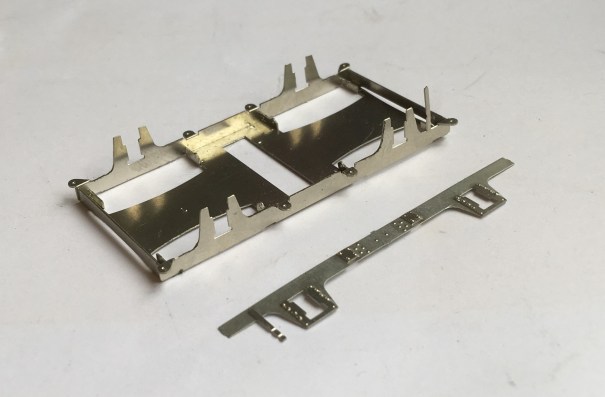
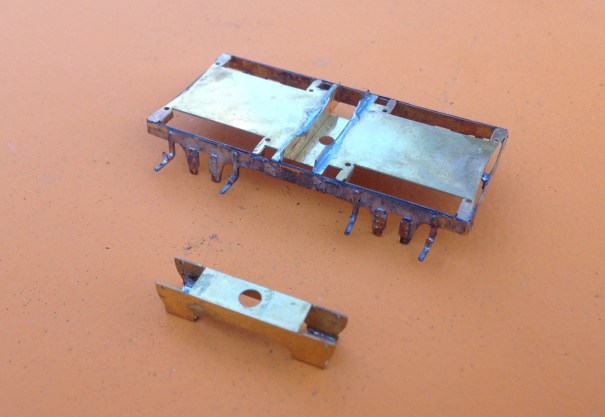
I no longer affix roofs firmly to the body of my coaches as makes both the building and the painting much easier. The downside of this is that there is the challenge of keeping the roof on tight without there being any visible joint between the two as this looks terrible. The solution I now use is to clamp this to the floor with 10BA bolts by way of brackets as can be seen in the photograph below.
As built, these coaches had full length step boards but they lost most of these through their life. They were electric fitted from the outset. The chassis below is close to finished except I have run out of vacuum cylinders so these will need to be added, along with the vacuum pipes.
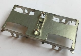
The bogies are also a key part of the proposed kit and are something that I have been working on with Justin Newitt of Rumney Models – the idea being to combine the sprung bogie design that he has prepared with cosmetic etches for the sides and then the castings from Lochgorm Models or perhaps our own in due course. The bogie is quite sophisticated with both primary and secondary springing – the latter is on the bolster and is as below.
The primary springing is on the axleboxes and has bearing carriers, much like the Bill Bedford sprung W-irons. There are still some wrinkles to iron out so it is not there yet but they do make up into some pretty neat bogies; don’t you think?
The only area of the first test build that truly did not work was the corridor connections and it is going to be a case of back to the drawing board for these but other than the final few bits to be completed, the build is finished and I think the vehicle is handsome.
So, off to the paint shops soon, but there is a bit of a holiday to squeeze in first!

Dia 51 Full Brake – Test Build Part 1
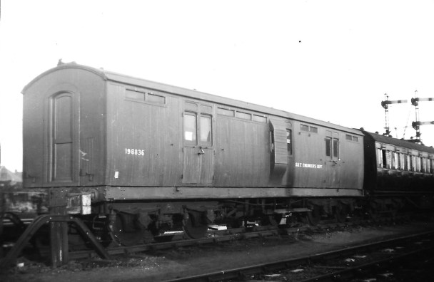
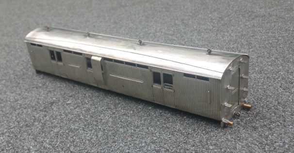
Following the last delivery from the etchers, it was time to get on and do the first test builds. First up was the dia 51 Full Brake. This vehicle was one of the later coaches from the Highland Railway and was of similar design to the cove roof corridor coaches that have been available from Lochgorm Models for some time. They were also amongst some of the last highland coaches to service as tool vans etc. This is what one looked like late on in its career after its corridor connections had been removed.
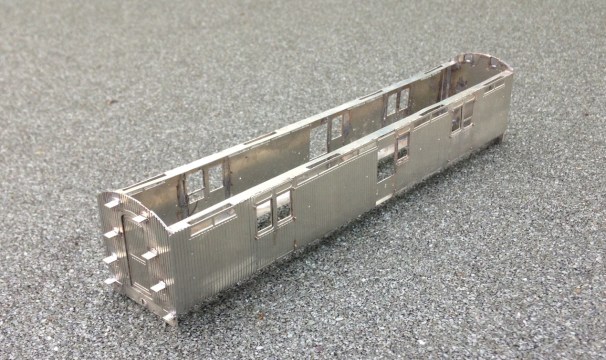
As with my efforts for the scrap tank, I am seeking to try and be a bit smarter with some of the kit design to draw together ideas of assembly of my own and also those of others. So starting with the ends, these will be made with a double skin to both provide the footsteps and, less commonly, some tabs to allow the sides to be secured to them.
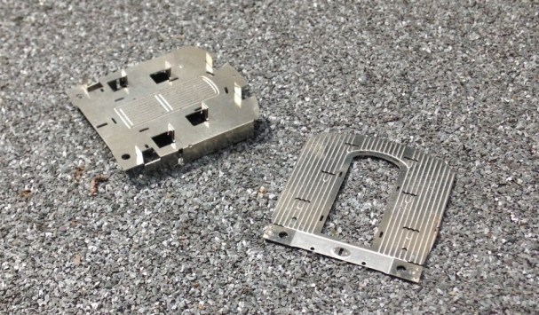
I have always found that too many etched coaches have flimsey sides that become distorted as they are made (or when ham-fisted me does anyway). Therefore, I have designed this such that the head and base of the side have significantly sized stiffening pieces, as can be seen below. These are designed to interlock with the tabs at the ends such that most of the locating of the parts is largely defined by the kits components.

Once the basics of the shell are together, this is what it looks like.
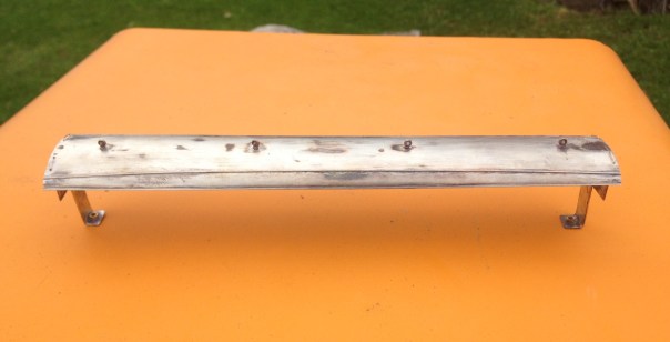
The roof proved to be one of the most challenging parts of the build. I had originally designed this with an inner to form the shape of the roof and then a thinly etched outer layer to go over this to provide the rainstrips and other detail. It proved too difficult to get the two to laminate well or even be rolled to a similar curve.
Instead, therefore, I ditched the outer layer and relied only on the inner. This had been half etched on the underside to assist its rolling to the curved profile. I found that it was still difficult to roll the roof due to the tightness of the curves at the extremity of the roof but by simply using bending bars it was quite easy to put the curves in with a limited amount of faceting. Faceting is where short straight sections with bends to the next short section that gives the impression of a curve. Once this was then filed on the outside to smooth out the facets, a smooth curve became pretty good. Thereafter, it was necessary to form the rainstrips with wire and file them back to square sections and as you can see, the effect is pretty convincing.
The underframe and bogies are to follow, in part 2.
Gresley Buffet – Part 3; Corridor Connections
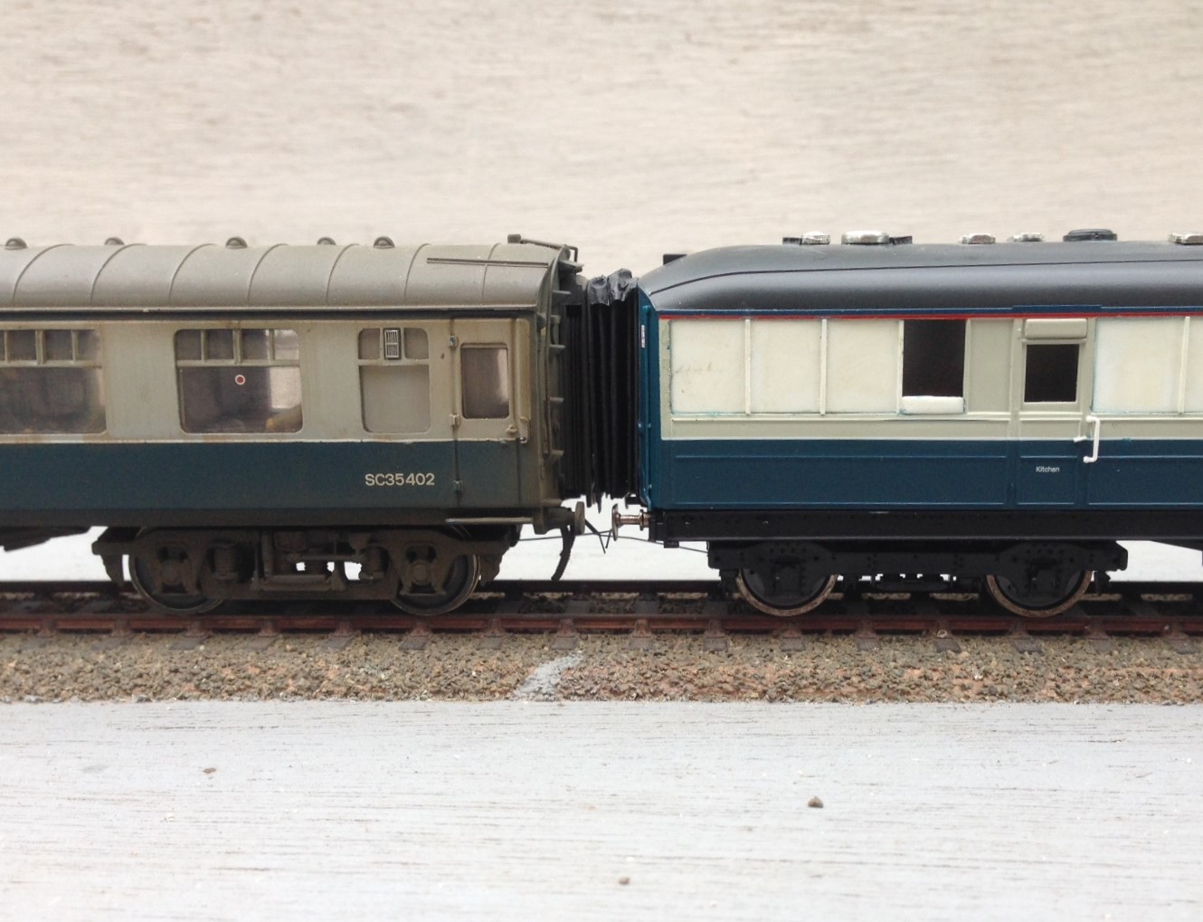
I guess that it is pretty difficult for the RTR manufacturer to take a stab decent corridor connections because they have to design for toy train set curves and clumsey hands but it is a weakness of all proprietary coaches. Hornby’s buffet also seems to have overly skinny corridor connections and most noticeable they are mounted too low – they should finish at the meeting of the roof with the ends.
Whilst it is possible to simply slice off the connections off and move them up, I chose to remove the and them with some produced by Comet – as this is an LNER vehicle, you need the Pullman type. The core of the operation of the corridor connections are the bellows which are formed with a pair of sheets of fairly stiff paper. These have slots cut to half their width and are then folded into a concertina shape, with the slot between the folds. Two such pieces are then offered up to each other, with the slots opposing and these then slide over each other as shown in the first picture.
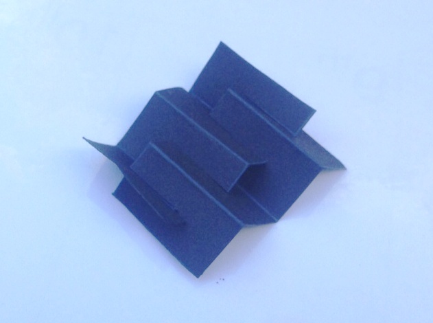
To create a concertina bellows like this.
Thereafter, the etched end plate is attached to one face. Whilst not provided in the kit, I formed a second plate from plasticard and affixed this to the other end. it is important to ensure that no glue gets on the concertina sections of the paper, as they need to be capable of compressing with minimal effort to correctly operate without derailing the carriage.
This is how Comet envisage that the completed connection should look like but I felt that the bellows did not look very realistic, especially from above where the crossing point is all too obvious. In practise, the top of these connections had a fabric roof and applying this dramatically improves the appearance of the connection and has the added advantage of providing some control to the operation of the connections which do tend to expand out and look rather flabby!
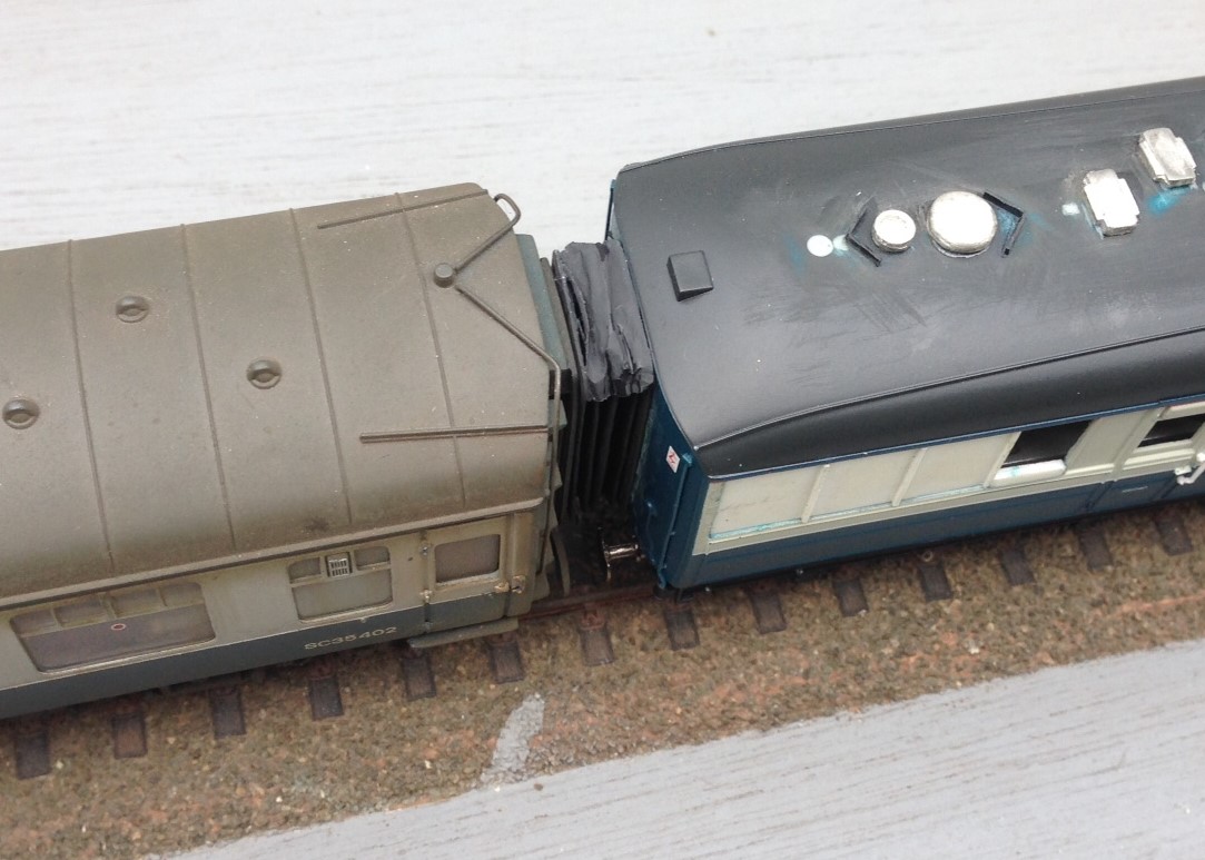
I dealt with this by putting the rain hood on the top of the connection, which is afterall prototypical (and makes a huge difference to the appearance as you can see). I did this in a manner that meant it acted as a restraint to the movement of the connection. I acheived this by only gluing it at the very back and front of the connection, so that the bellows could move unimpeeded but once they had moved to the required extent, the rain hood pulled tight and stopped them going any further. I found that doing this at the top was not sufficient as their movement continued at the bottom and they took on rather drunken appearance – however, this was solved by simply repeating this at the bottom.
Key to getting this to work was to use material for these restraints that was ultra flexible. I did think about trying silk but settled instead on the rather more mundale – plastic from a bin liner. This is remarkably thin but is still tough enough to hold the connections. A tiny dab of super glue at the front and back and then it can be laid onto. It is important not to sigh with releif for some time though – the stuff is so light that it blows away at the slightest. So this is what it looks like:
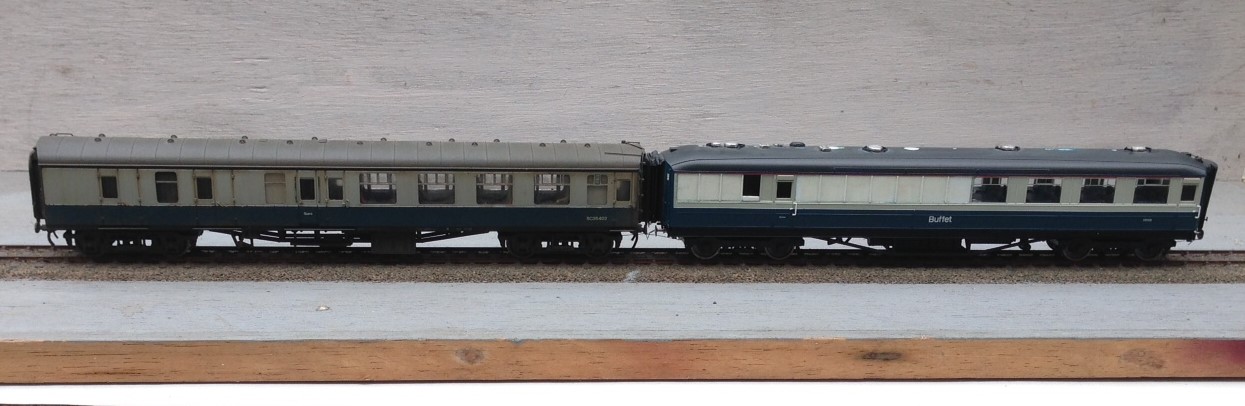
I think that I have still allowed the connections to be too big and if there were two together this would definitely be true but next to a rather skinny Bachmann corridor connection, I think they look pretty good (and a big improvement on the originals).
The Cruellest Cut – Carrying on with Hornby’s Gresley Buffet
The first task in dealing with ready to run vehicles is to work out how to get into them – not always as easy as it sounds! In this case, this is achieved by slipping finger nails between the sides and the underframe solebars; this releases four catches and the top pops off. The interior then slips out without bother but the glazing is a little more tricky as it is secured with some very gooey glue. Whilst this releases the perspex relatively easily, it was difficult to then remove the remaining glue – I found it best to do this by rolling it with a thumb and accumulating the residue on a scrap of paper but it was a pain getting it all off.
Prior to attacking the model with knife and blade, a sensible precaution is to protected all of the areas that are not to be cut with masking tape, which you will see I have done. This was effective but I did find that I dislodged a filler pipe when I removed it, so perhaps a slip of paper over these would be prudent next time.
Then it was time to get cutting; I varied between using a razor saw and a scalpel to cut a grove by using parallel cuts but in both cases it is important to cut to the waste side of the finished line. I found that it was best to work to an existing bead line, even though when working to the saloon end of the coach the bead was the side of door jamb (this is where I found the knife best and I made sure this was one of the first cuts to be made) so that there was no stress on the thin piece of material. By the time the cutting had been finished the holes were quite big!
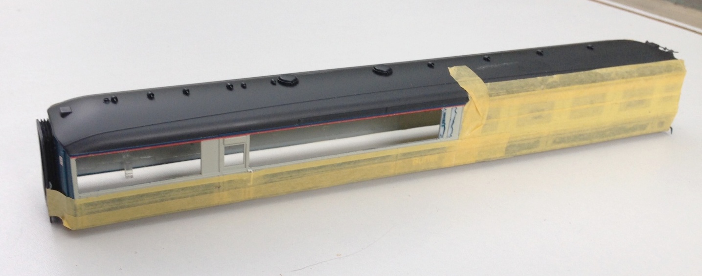
Nearly all the cutting done now; but the last panel to the right did also get cut away
It pays to dress the sides of the opening with care so that they are straight and square as this makes the fitting of the infill pieces much easier. These should be cut fractionally over large and then sanded back by small degrees checking regularly to determine if it fits and taking care to ensure that the square/straight edges are maintained. Once it fits, I let it into the hole and secured with butonone and then left it to cure for a couple of hours so that I did not disturb it when I subsequently fitted the beading. This was formed with 0.2 * 0.2mm microstrip and these needed to be set out with considerable care – aided by the use of venier calipers – to get them regularly spaced and vertical. Even the most minor of inconsistencies detract from the affect.
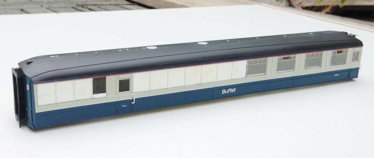
Replacement panels now in place, including a partial infill of the window by the door
Next up was the removal of the various roof vents and cowls as these too changed. I suspect that these were no consistent across differing vehicles and it is quite difficult to determine what goes where but I was assisted by some photographs from here. Utilising some of the vents salvaged from the Hornby model and also from Comet Models, the latter generally with their shields filed away as the roof views I have have straight flanges as shields – which I formed with brass strip as I though plasticard would be knocked off.
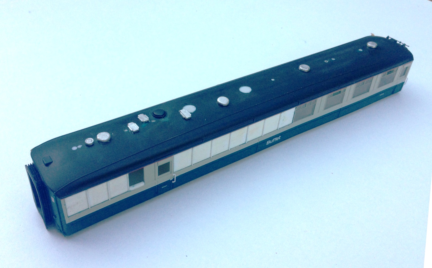
Roof vents in place, based on a photograph of the roof of 9132 at SRPS in the 1970s. I also noted that the alarm gear on the roof was at the other end of the vehicle in comparison to the Hornby model, so this is going to need to be cut away and recreated at the opposite end.
