Blog Archives

What Have I Been Doing…………..?
Gosh, another year where my intentions to increase my rate of posting have got away………..
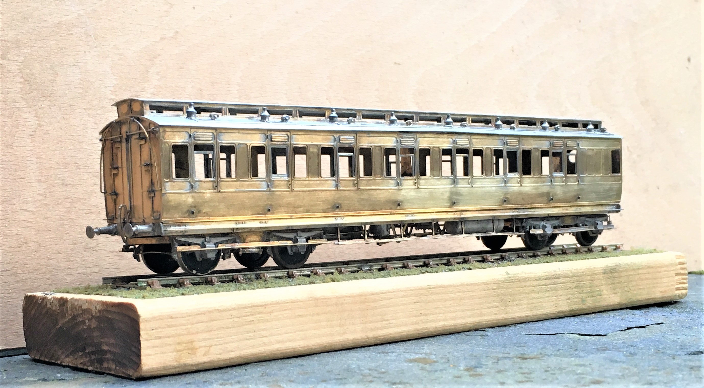
Whilst work and home life have intruded, I have still managed to get some modelling done; including a rake of NER coaches for John James for which i do get something in return in due course.
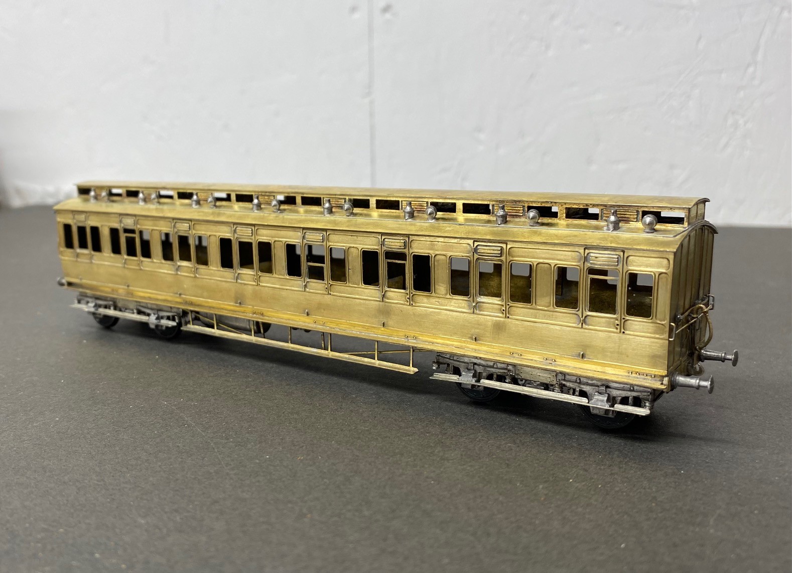
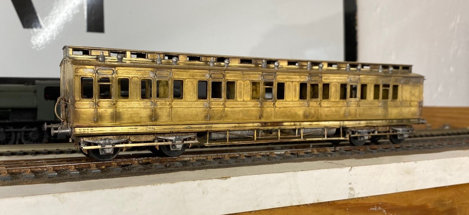
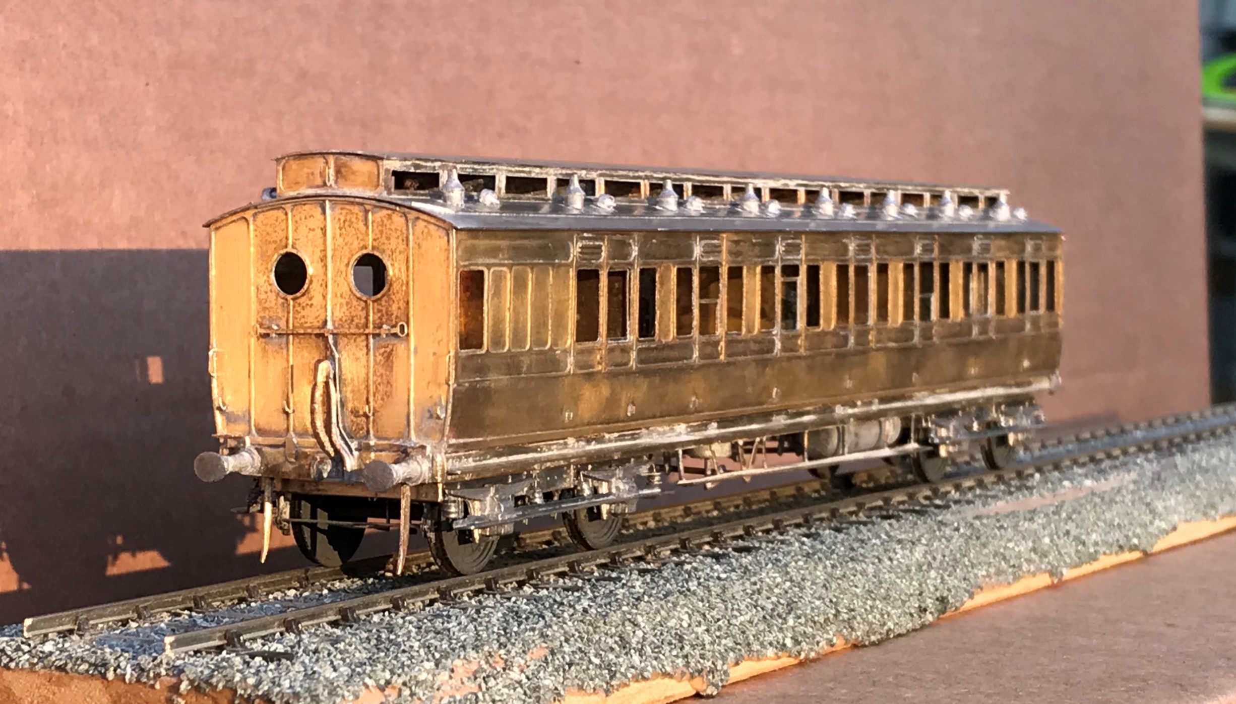
The rake had a pair of three compartment thirds, of which this is an example:
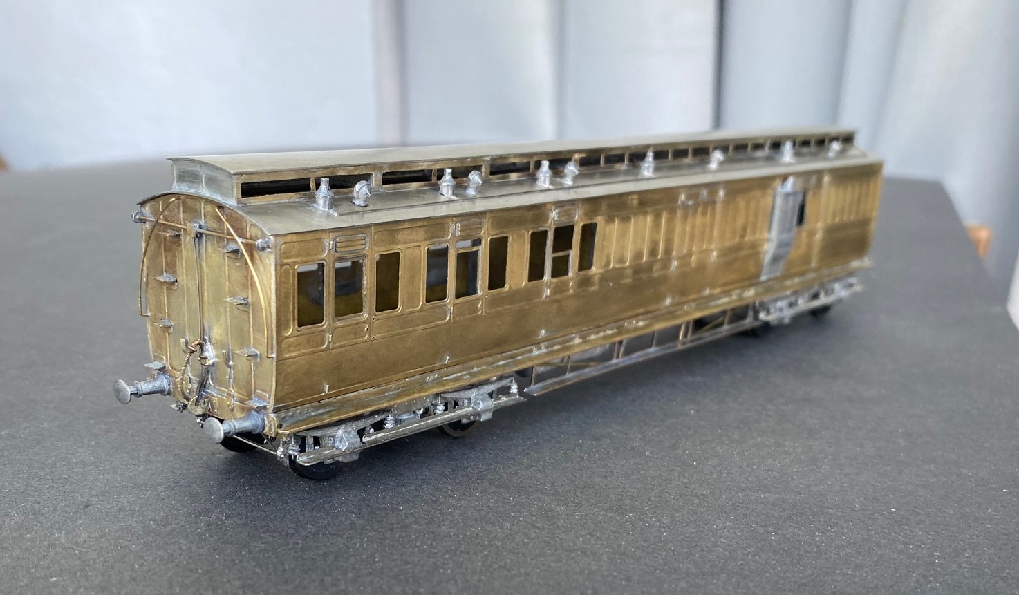
All of the coaches were constructed from D&S kits on my Miscellany Models Fox bogies with replacement roofs formed of nickle silver sheet. I find that the plasticard offering in the D&S kits to be their weakest point. The problem with this is that if you make your own roofs i find you might as well also cut out the section below the clerestory – it makes a huge difference for the coach to be illuminated from above. The issue is, that there is a lot of work in these roofs – I found that for each there was 15+ hours of work just in the roof!
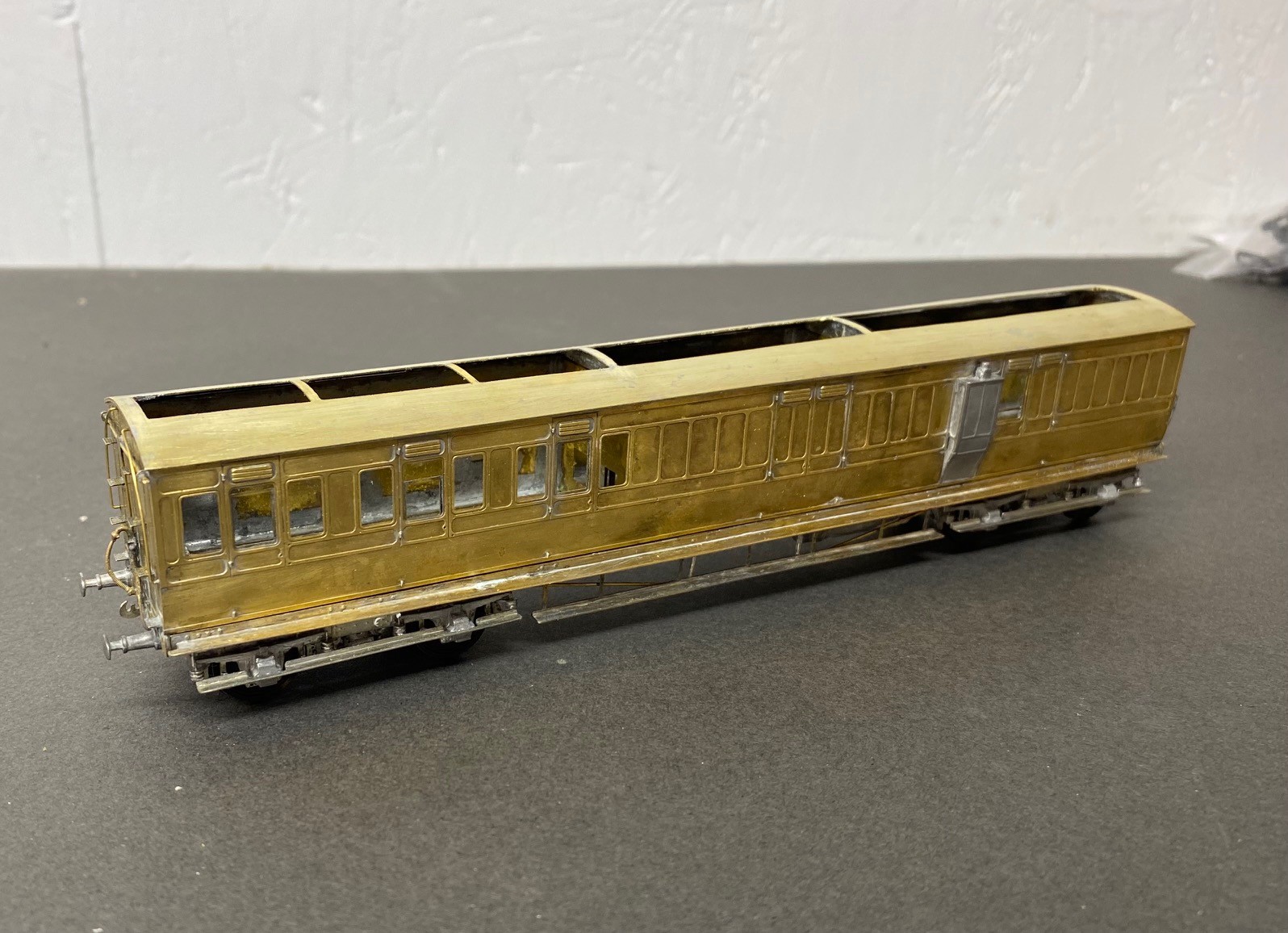
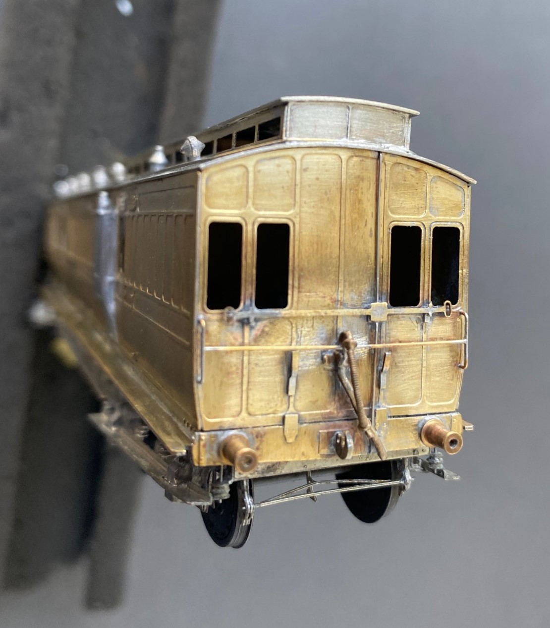
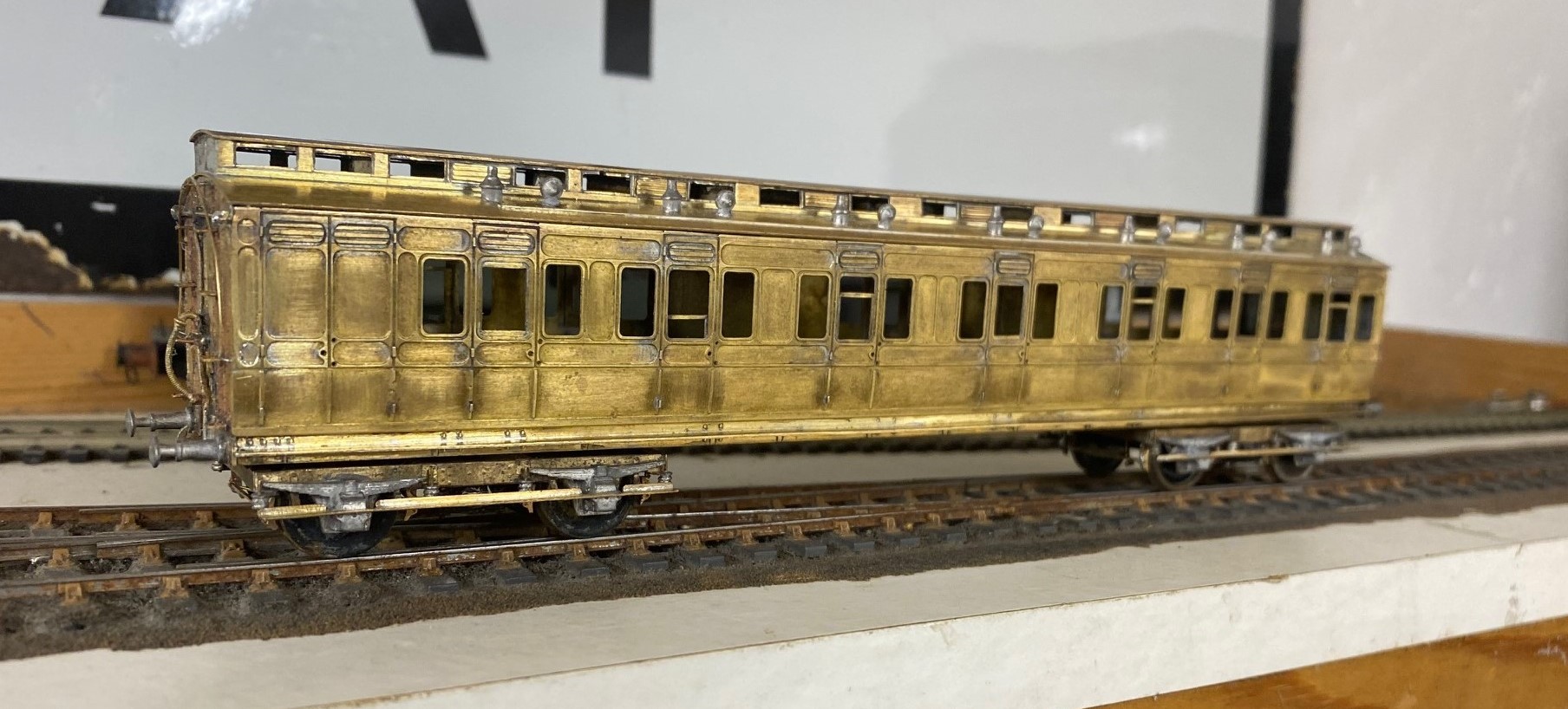
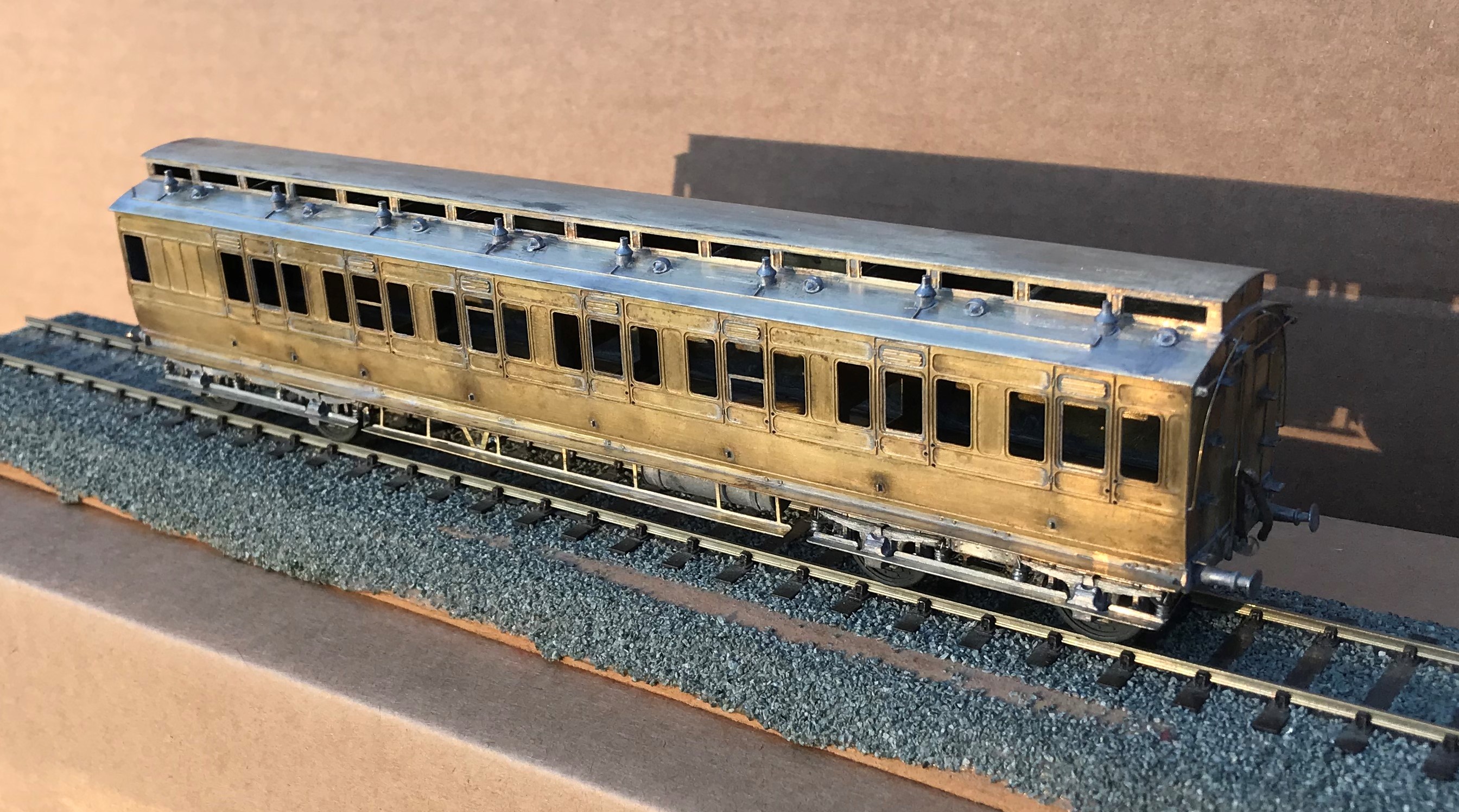
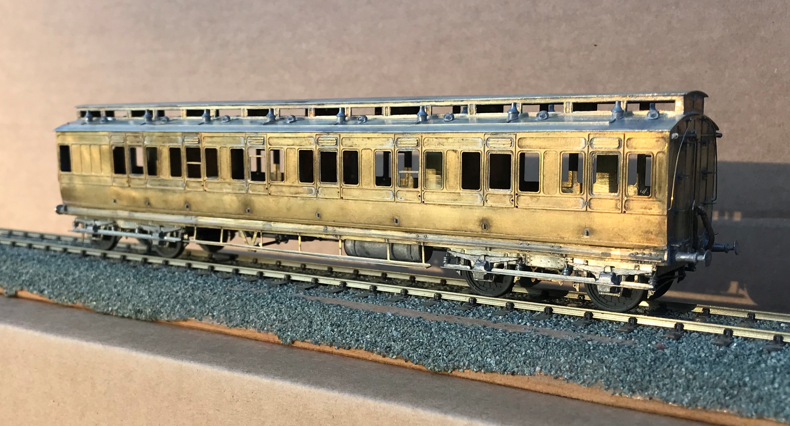
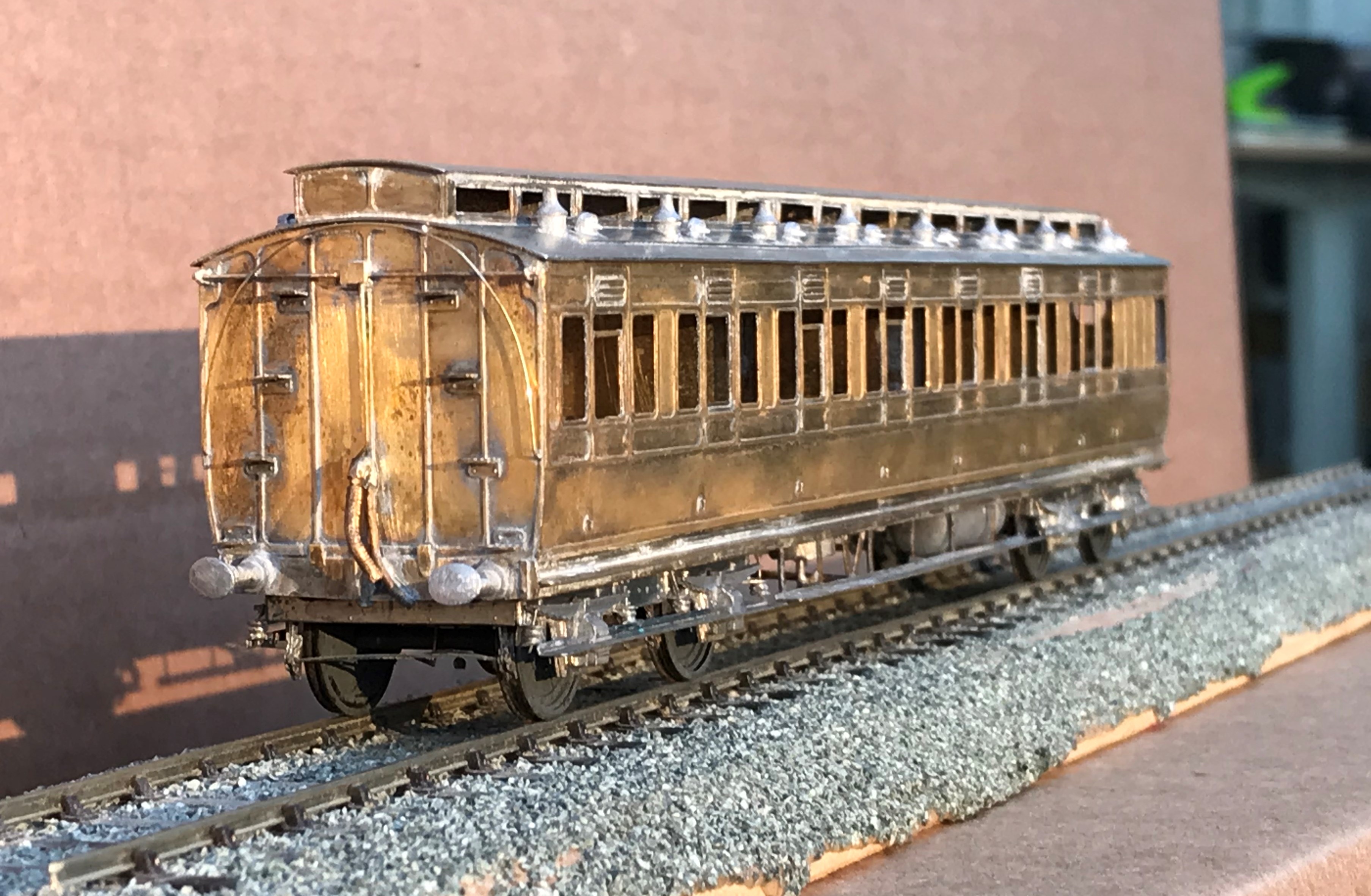
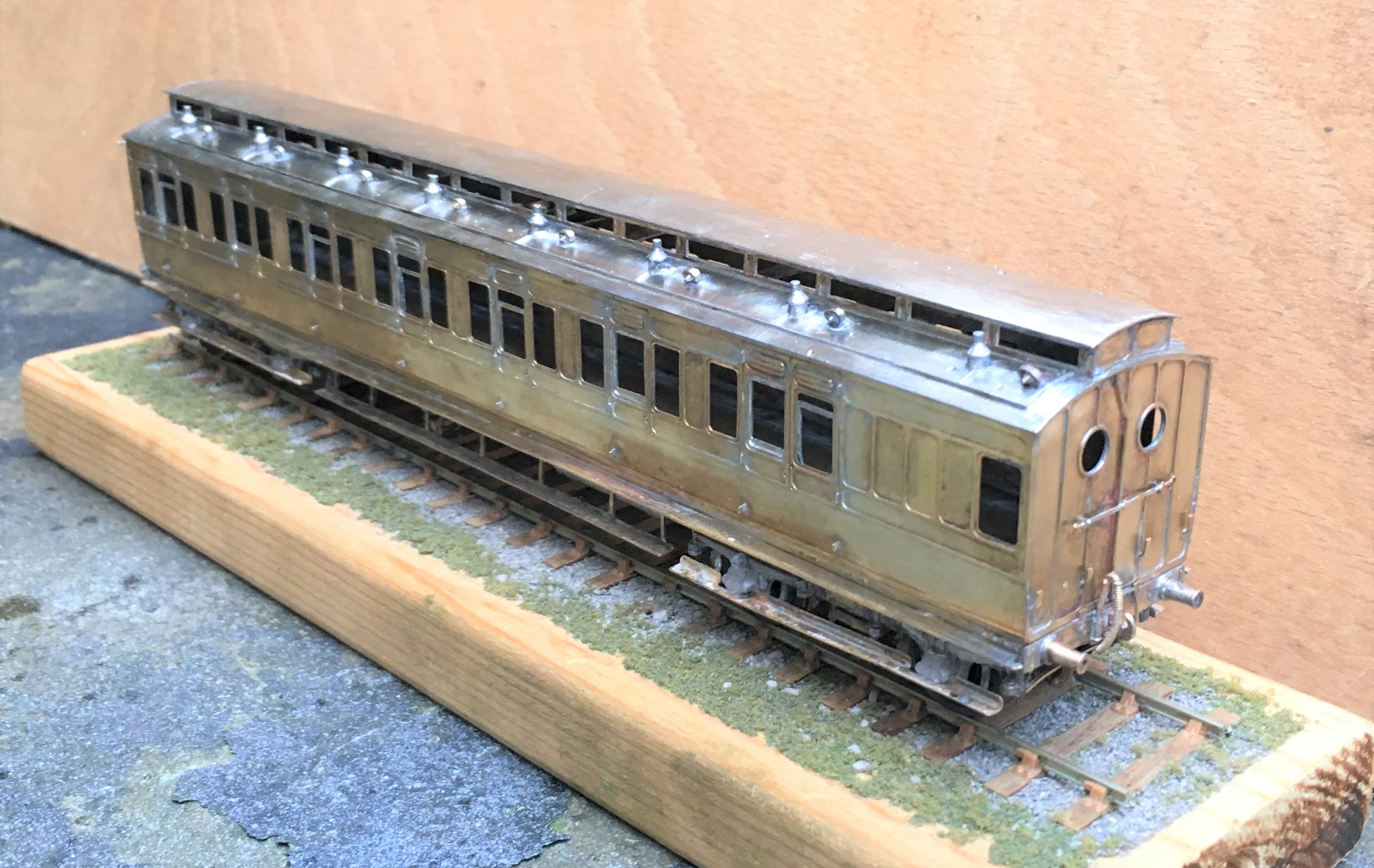
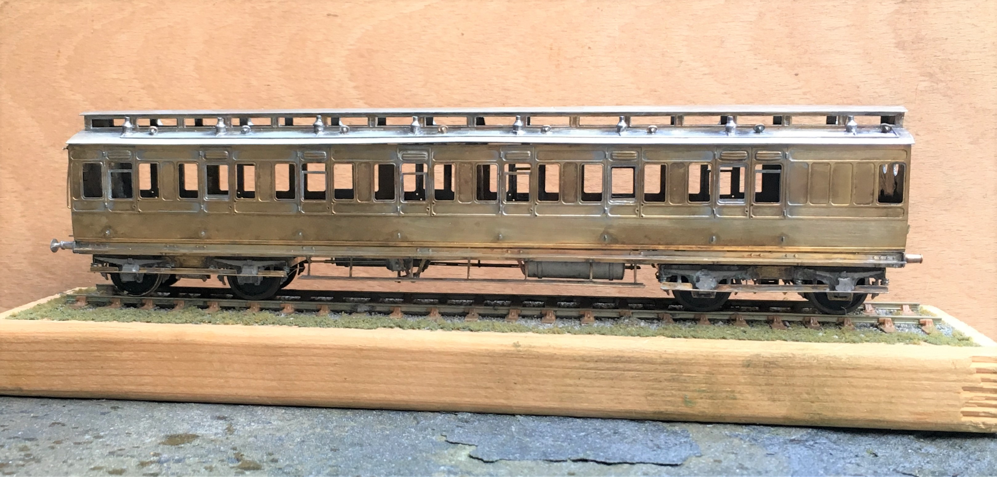
Also in the rake is an all third, which is probably my favourite of the build as it feels quite “pure” and also wihtout the problems of the composite…….see below…….
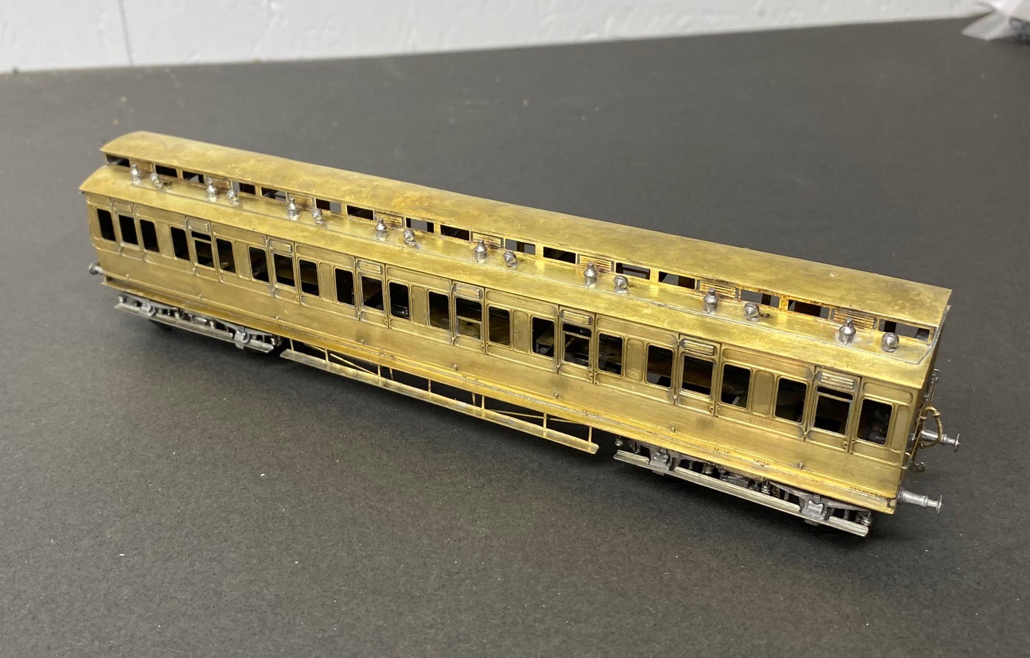
The rake only needed a modicum of first class accomodation made up from a composite diagram 7. Alas, this had a challenging problem that needed to be overcome, with the clerestory side pieces. These were much shallower than those on the other kits orwith the ends supplied in this kit. In addition to being obviously incorrect given the inconsistancy but the frames around the glazed lights were stunningly delicate. I regret persisting with this, i should have just drawn up some replacements in CAD and popped them in the next etching order.
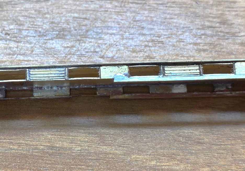
However, i solved the problem by soldering a flat strip, 1.5*0.5mm along the base. in theory it should be to both the top and bottom but that was not realistically possible and I decided life was too short. After much fighting, cussing, fighting, screaming and more fighting, I did get it there, as I hope you can see.
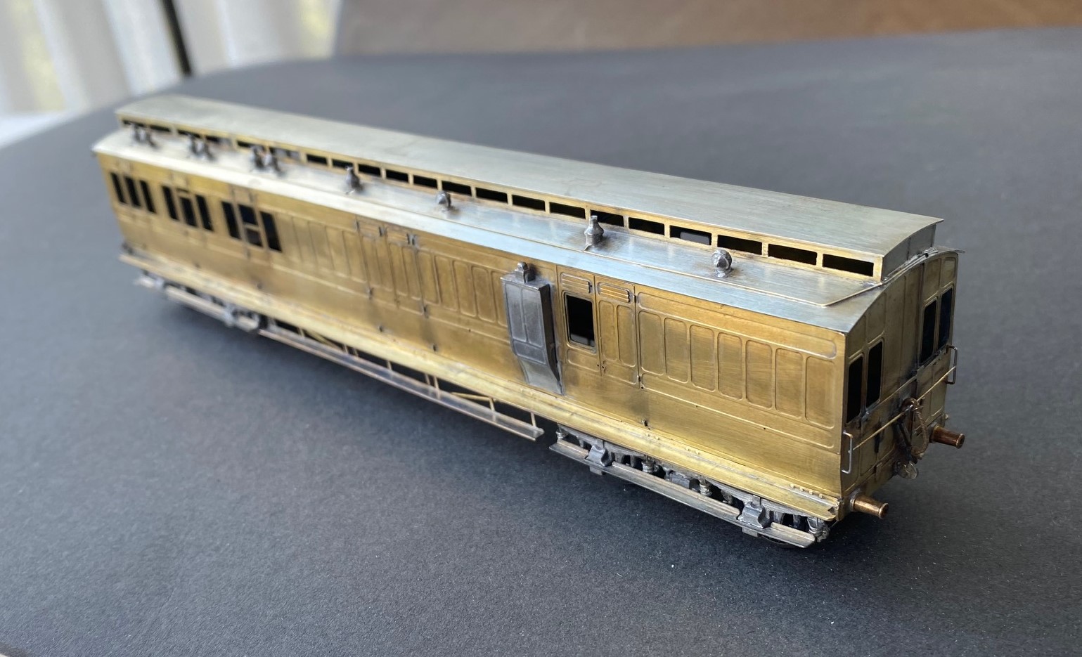
I was asked to do these as gas lit coaches and therefore there is a bit going on below, as one might say.
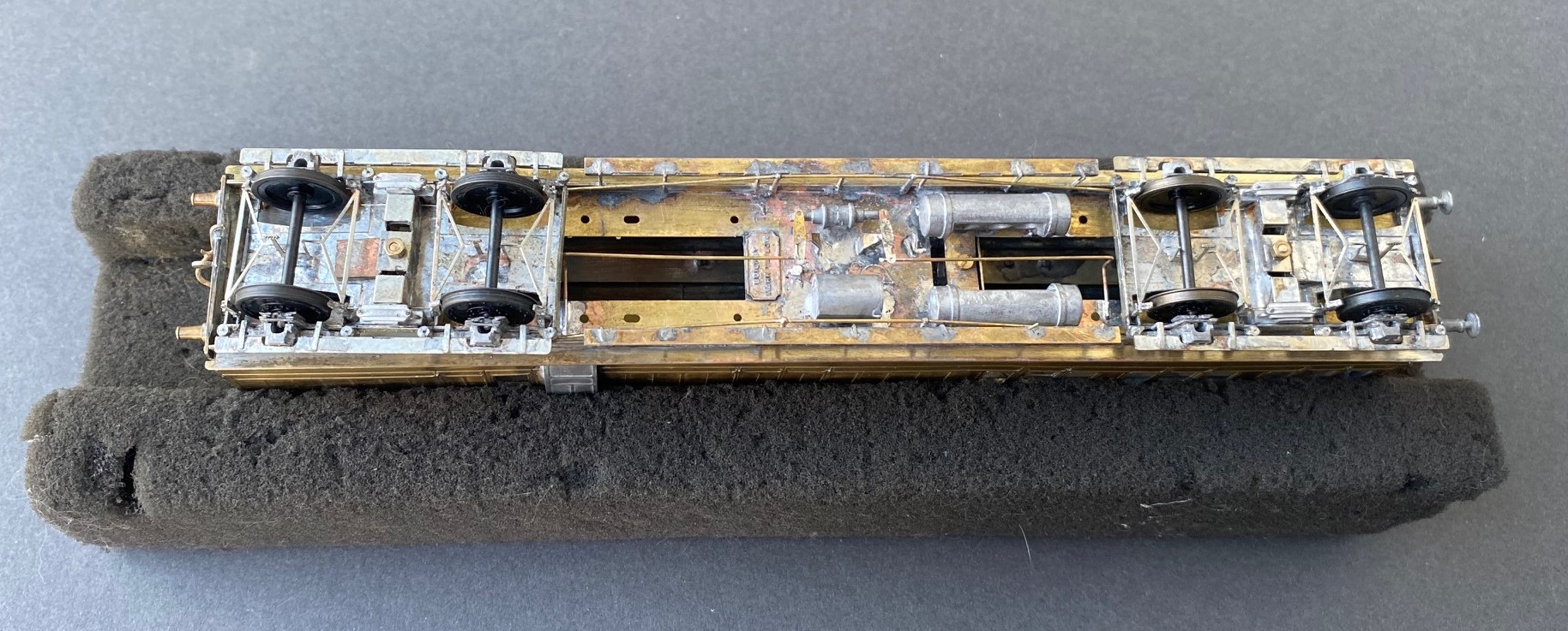
As the coaches were quite long lived, they went through many detailed changes. for anyoen who is contemplating building some, I would heartily recommend reading David Addyman’s notes on how he built his in the Scaleforu Forum https://www.scalefour.org/forum/viewtopic.php?f=39&t=7210&p=101662&hilit=ner+coaches#p101662 David’s coaches are modelled in the 1930s, so have different lighting arrangements, footsteps, bogie spring dampers and sides to the clerestories. Lots of things to be aware of if you are doing something similar.
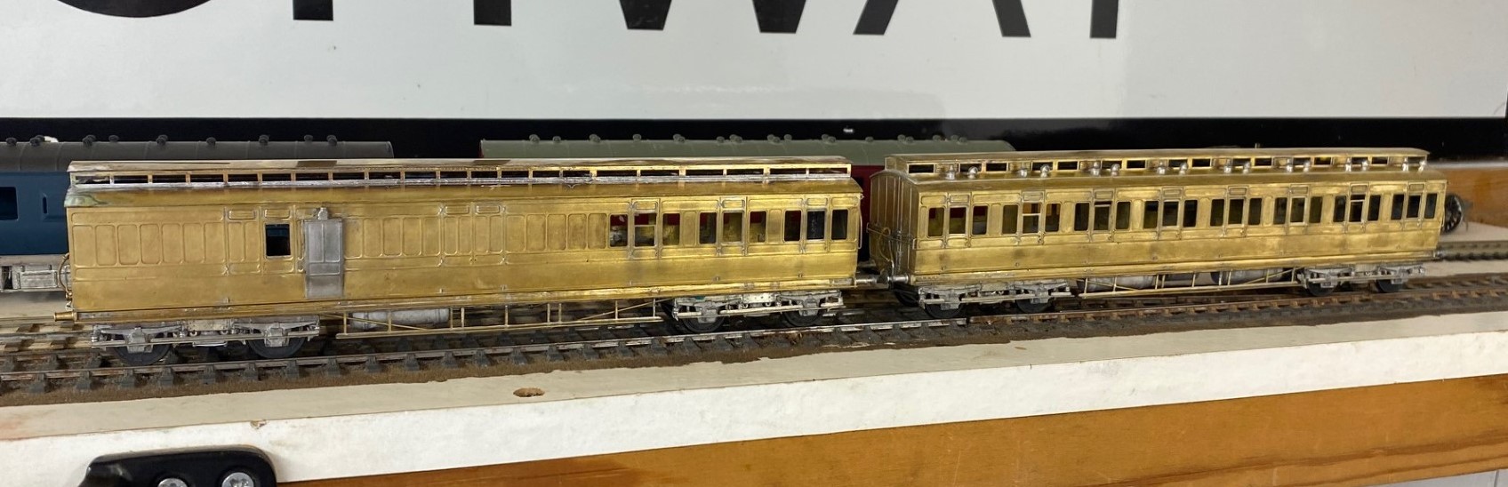
At the end of this rather mammoth build, I had four coaches that i was rather proud of. They look rather fine on John Wright’s Benfieldside viaduct.
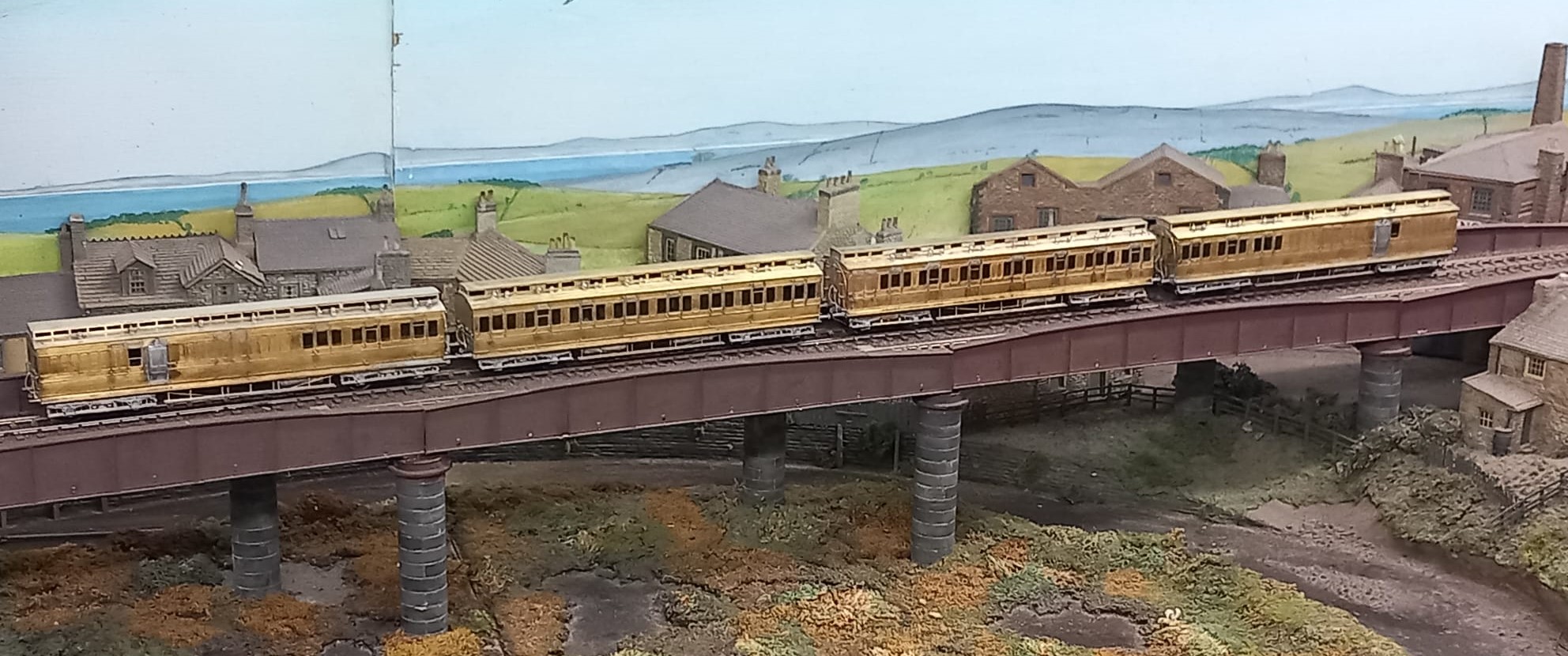
I am also pleased that i do not have to paint these; i am still looking for my lining mojo. I had it as a teenager, but have grown shy of lining. Maybe something for the Christmas break?
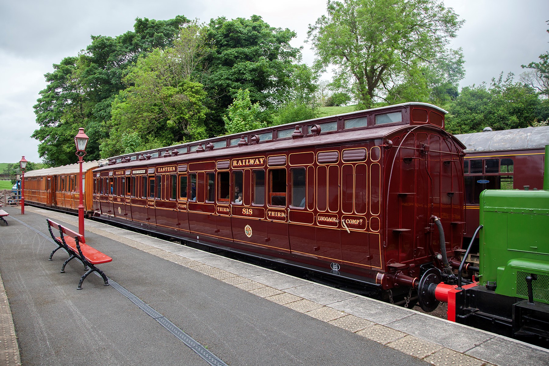
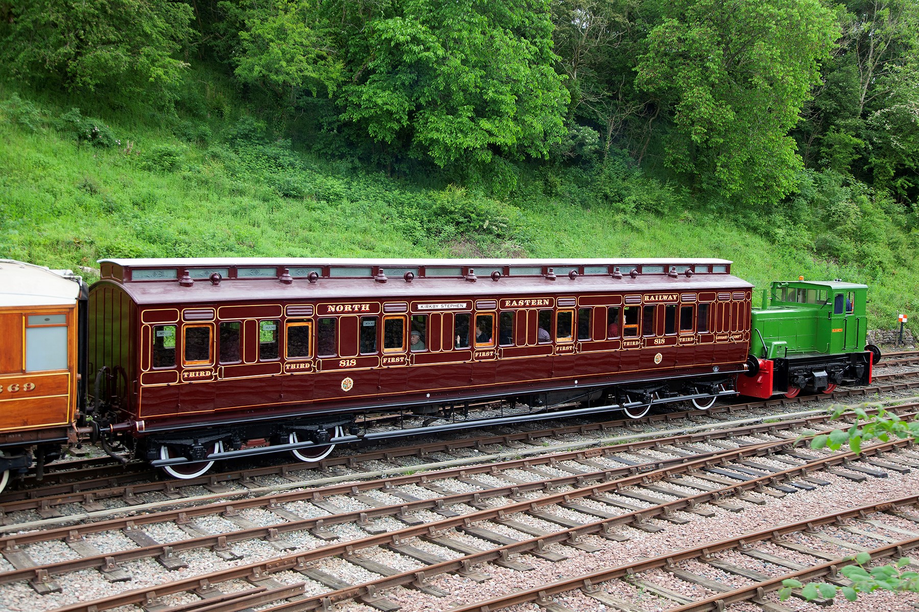
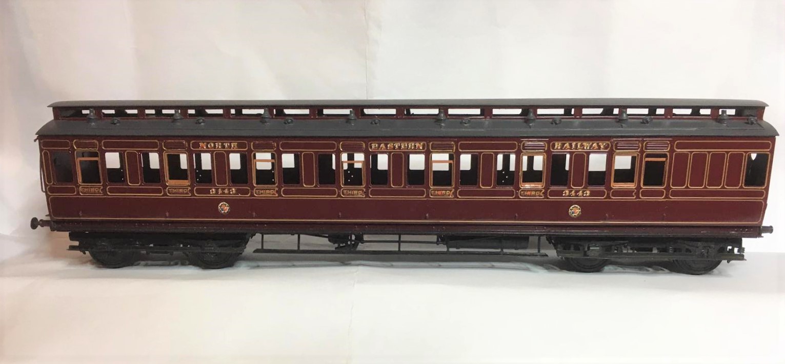
In the meantime, here are a couple of pictures of the newly restored NER coach 818 at Kirby Stephen, courtesy of the Beamish website. Does’t she look magnificant? I really must get up to see her.
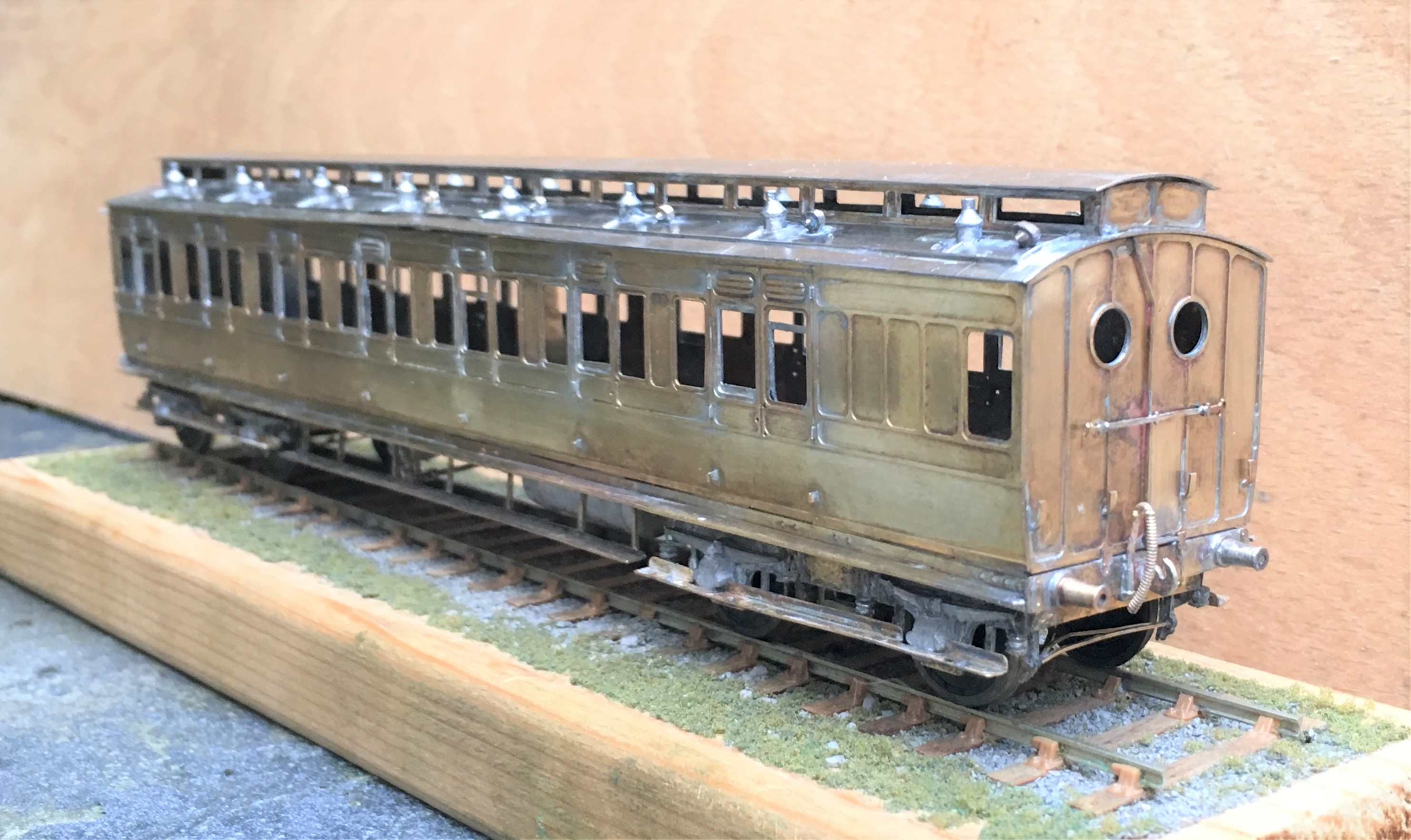
The Other Auto-coach
Some time back I posted about the construction of a NER autocoach that I was building for Benfieldside and subsequently what it looked like once painted by Warren Heywood.
The NER generally used these in pairs, with a loco sandwiched between, although they did go out singly and even as quads. In this case, the Benfieldside team wish to operate them as a pair, as the bay to the right of the layout is conceived to receive such a train, with a NER / LNER G6 in between. This means that there was pressure to build the second from the moment I handed the first over. They have recently given me a favour, so it was high time I repaid it.
It is now completed down to the final check over stage (which has indicated that I need to put the steam heating pipes on – doh!) and then it can be delivered. So I have braved the fading light this afternoon (so sorry about some of the depth of field issues) to take a few pictures and to prove to the fellas it is done!

I completed a few personal upgrades to the kit in both this and the earlier autocoach. Chief of these is around the roof where I ditched the plastic roof and replaced it with rolled brass. This was formed of 0.25mm to give it a tangible depth, which makes its rolling a fair challenge. Add to this, I elected to cut out the portion below the clerestory, so that it was a clerestory! By the time I had added the gas lines and the various gas lamps and ventilators, I reckon there is around 20 hours in making the roof alone!
The prototype coaches were fairly long lived and numerous. They thus collected a good number of alterations and differences over time. I took some guidance to David Addyman and tweaked the kit in respect of gas lines, foot steps, handrails, footboards and gas cylinders. If someone thinks this is wrong, please don’t tell me!!
It always amuses me that the driver had to stand and peer down the line through two tiny windows. They lived in different times – could you imagine the snow-flakes tolerating this in the 21st century?
These are rather beautiful coaches, but not for the feint-hearted as there is a lot of time invested in these. I am pleased I do not have to paint it!

Back from the Paintshop
Some while ago, I showed a completed NER auto-trailer and mentioned that it was for the paintshop. Given that it was to go into full NER coaching livery I am pleased it was not my paintshop!
Well, it is now back and doesn’t it look fine…………..
The painting and lining has been done by Warren Haywood and as you can see there is little to fault about it. It now needs finishing with grab handles, buffer heads and glazing.
And that reminds me that I have another one in the box and they did tend to operate as pairs……….
Only the printable words for this Wednesday!
Hmmmm……..
A signal imitating a Fresian cow was not the effect I was after…………..
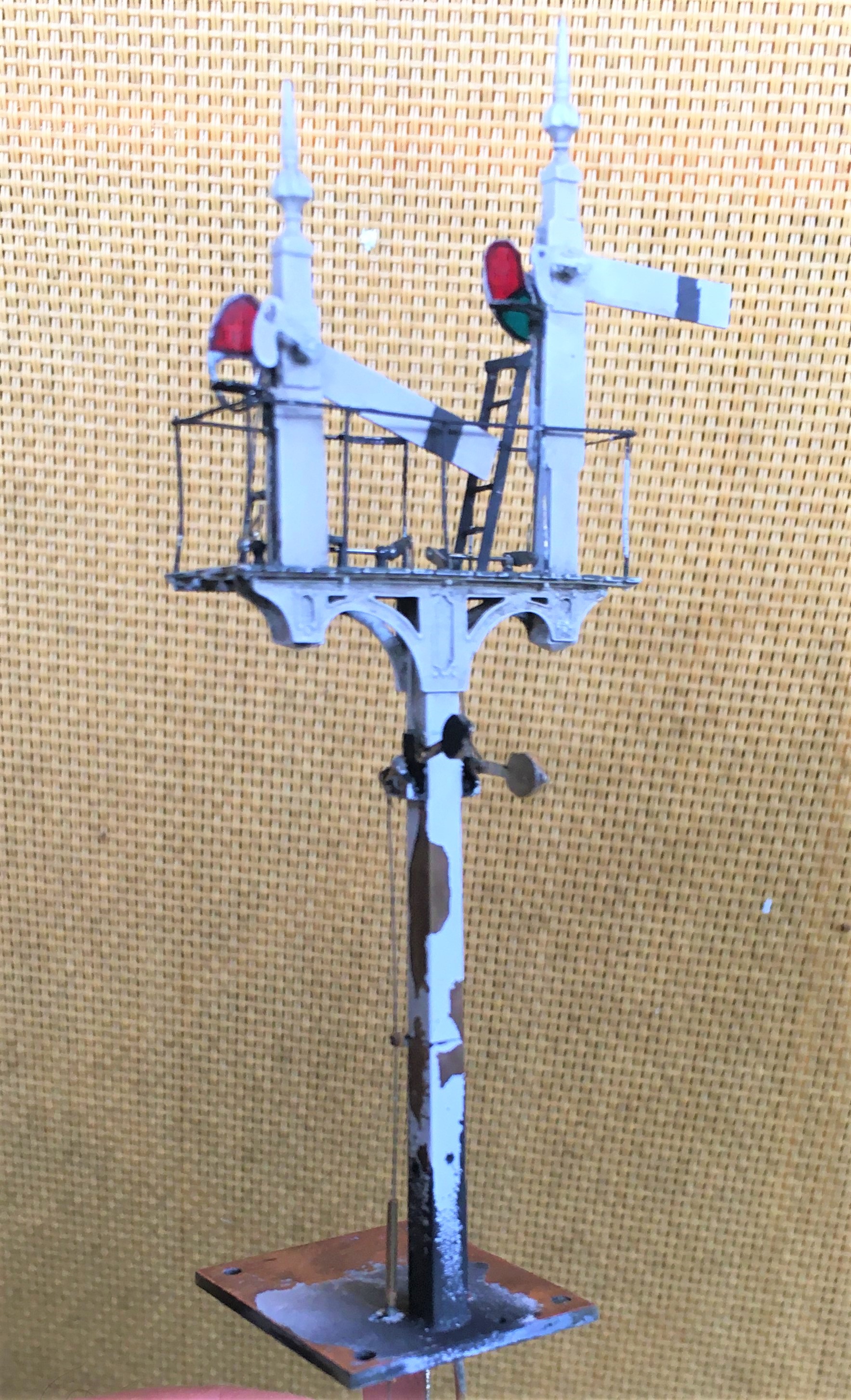
Halfords etch primer is obviously not that etchy!…………….. So someone will be waiting a tad longer for their signal than I thought…………

Benfieldside’s Missing Signal
When my friends acquired Benfieldside, it had suffered a bit of damage, notably to its signals – in essence it was this that got me volunteered for their restoration! One signal that puzzled us, however, was the up starter which was missing altogether and we could not unearth any photographs of it. Ultimately, we decided that it should be a two doll signal to also control the adjacent bay (which did have a signal, albeit inoperative) – so I have set to in order to fill this gap.
The line is set in Cumbria and is an imaginary westward extension of the Newcastle & Carlise line. In theory, therefore, it should not have the heavy cast iron brackets that the NER used. However, in reviewing the NERA’s signalling book, it became apparent that there were quite a lot of strays of signal designs, so I had an excuse to build one!
As this particular signal is going to be platform mounted, I did not need to sort out a mount for it and moved straight to the post and bracket, the latter being by MSE which I had in stock.
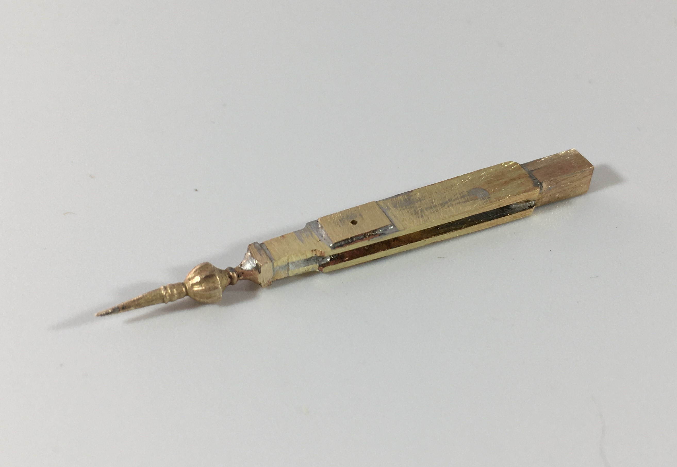
I then moved on to the prefabrication of a pair of dolls, each with slotted posts. This is made up of solid square section filed to a taper which is then cut and each end then has a tongue filed on it onto which flat plate is soldered either side to create the slots. I used a variety of temperature solders to ease this process but it was not easy – I did have one gum solid which resulted in a need to dismantle it and start again! As alluded to in the previous post, as these are slotted posts I had to depart from my usual practise of fitting the arms after painting as it is not otherwise possible to solder them to the spindle for the arm.
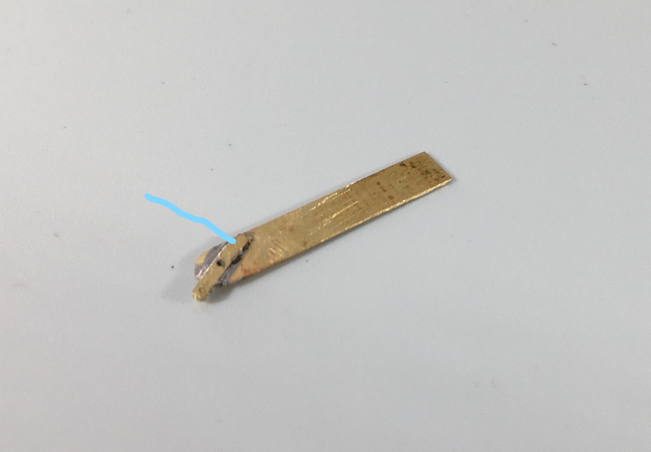
As mentioned in the last post, I came up with a bit of a dodge to successfully (well, in two of three cases!) to solder the arm to the spindle without gumming it up. By extending the ear that forms the point at which the operating rod attaches to the arm forward a bit (see the line below), it provides a point at which the soldering iron can be touched. If you use a slight excess of solder this allows the heat to transmit to the spindle and make the soldered joint.
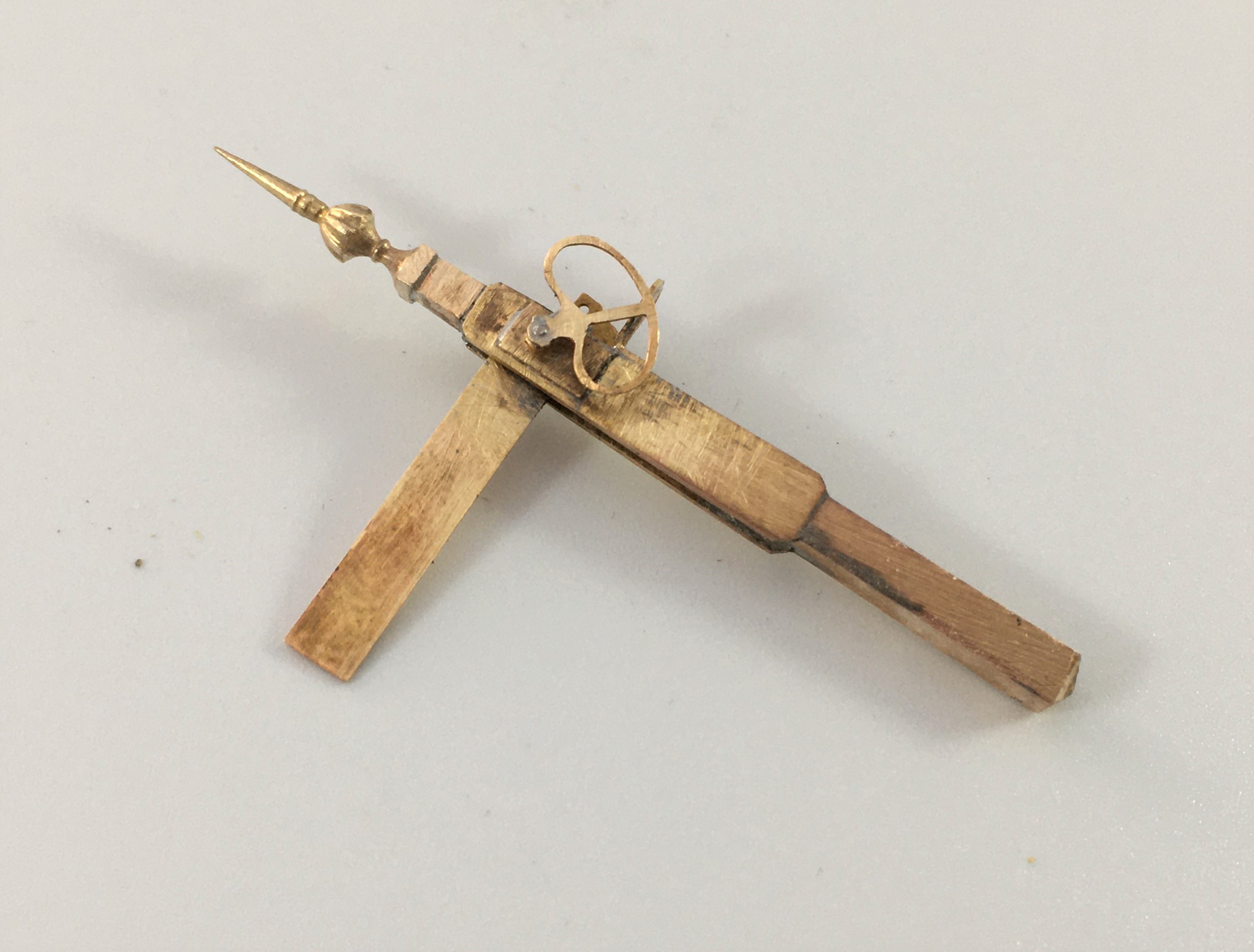
And this is what you get with a prefabricated doll, ready for the next stage of assembly.
And below of the pair of dolls now inserted to the landing.
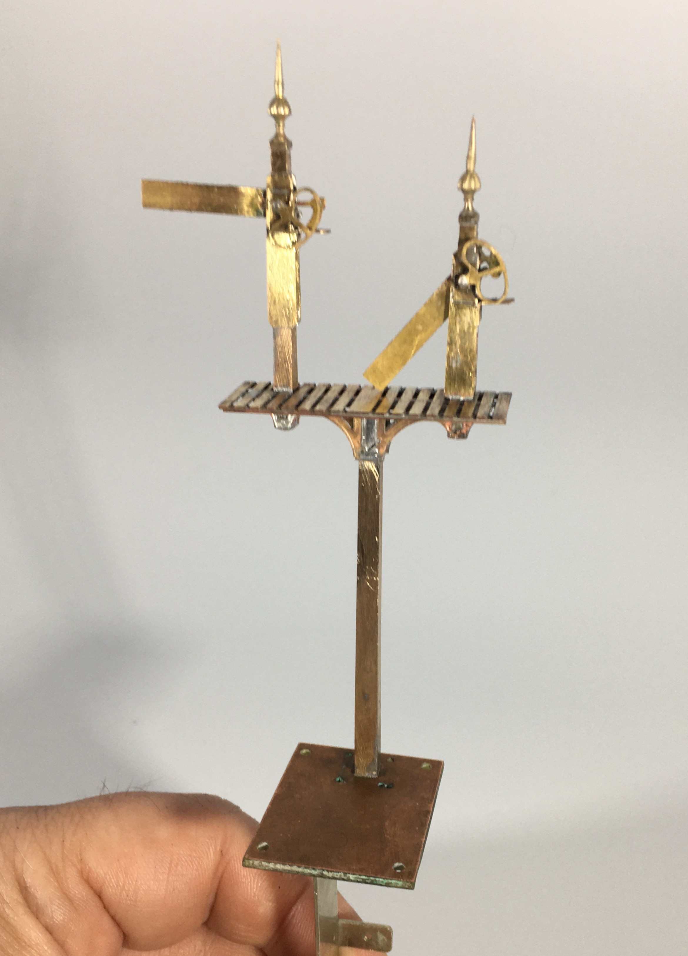
Even at this stage, there is still a lot of building to do as there are handrails, the main ladder, steps and ladders to the dolls, the operating mechanism transferring the movement to the dolls all to do. In respect of the latter(I used rocking cams in this case – you can just see the use of some handrail knobs as the bearings in the photos below, the cams will be fitted after painting.
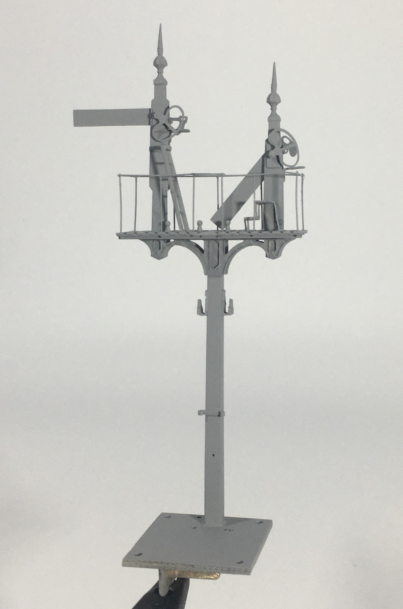
Slightly peculiarly, the NER built their landings in front of the arms whereas all the other signals I have yet built have these in the rear (excepting gantries, which can be either or both!). This view shows this most clearly.
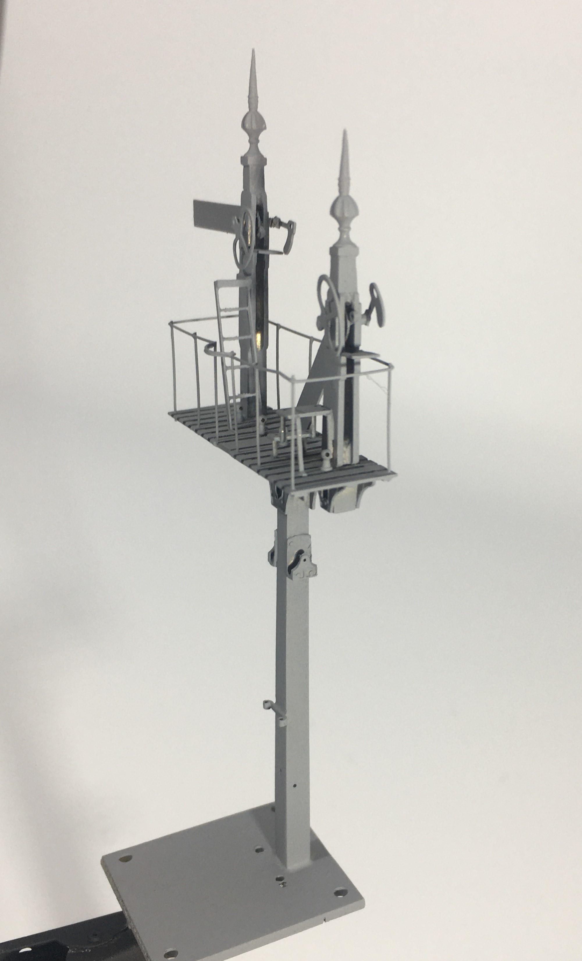
The main ladder is not visible in the views as I have made this detachable because it is much easier to spray paint these (and better, it is not easy to get a thin coat of paint by brush application and it thickens up the fine detail of a ladder too much.
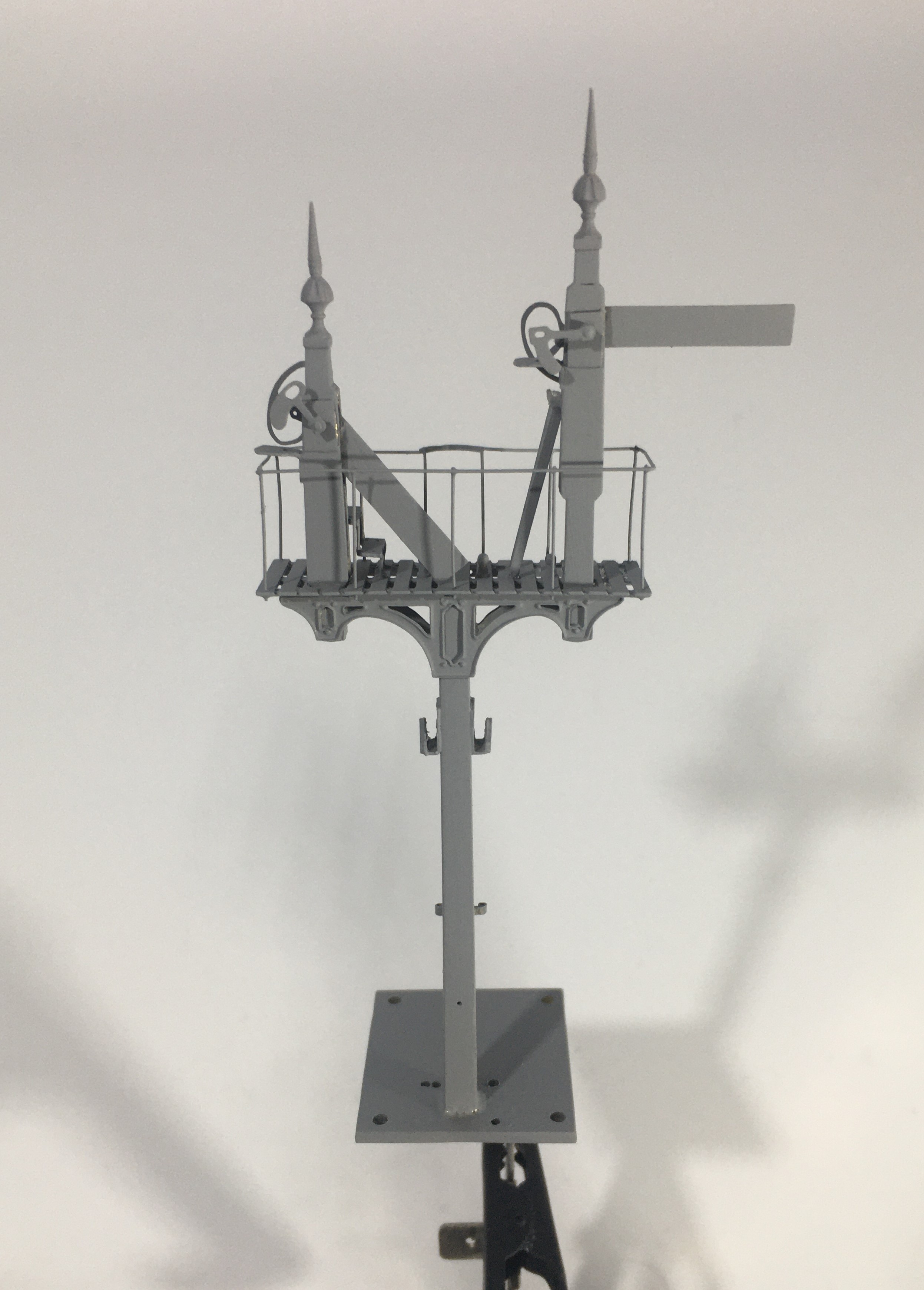
The grey primer is pretty cruel to modelling efforts but on the whole, I am pretty chuffed with this!
Tatty’s Top Tips – Signals
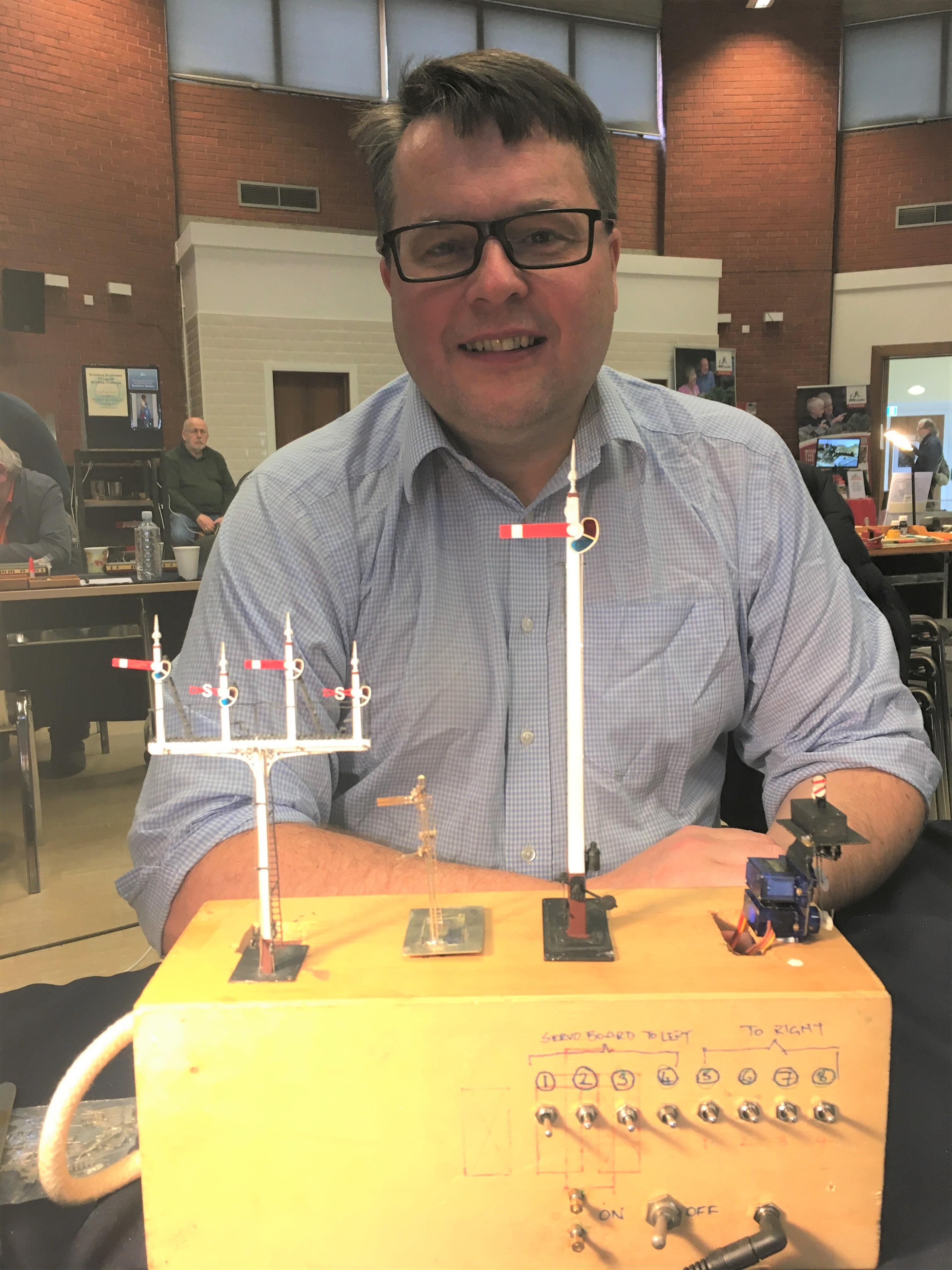
A mere three weeks ago, but a lifetime in the past now that we are in the middle (or more worryingly, perhaps just the beginning) of the Covid-19 crisis, I was a demonstrator at the joint EMGS/Scalefour Society skills day. These skills days are not really exhibitions and are instead aimed at passing some skills on to the visitors – thus they are primarily a hall full of demonstrators with only the odd layout or two to break up the rows of desks.
Here I am, in a shockingly creased shirt (!), and as you can see, I am demonstrating signal construction. I am pleased to say that at the skills day I had a solid stream of people engaging with the topic all day; so much show I had to pull down the shutters for a brief lunch as otherwise I really would not have stopped all day!
By way of preparation for the event, I thought about what I have learnt about building signals and distilled a list of my top tips. These proved to be the cornerstone of my conversations with people at the Skills Day so I thought it was worth repeating them here on the blog.
Planning Ahead
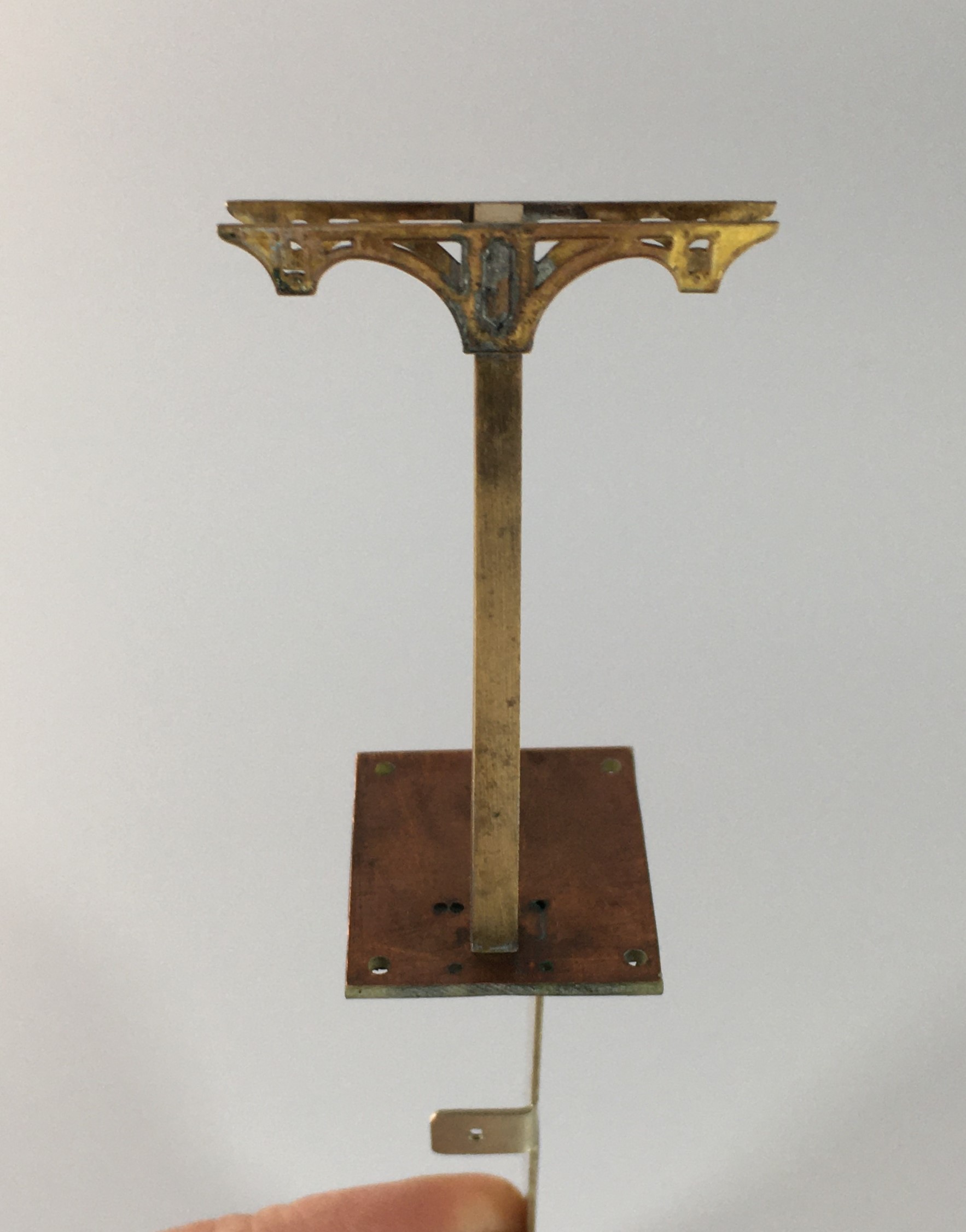
- Conceive how you are going to mount the signal; where and how, what is above the ground or below the baseboard – which might well mean you also need to;

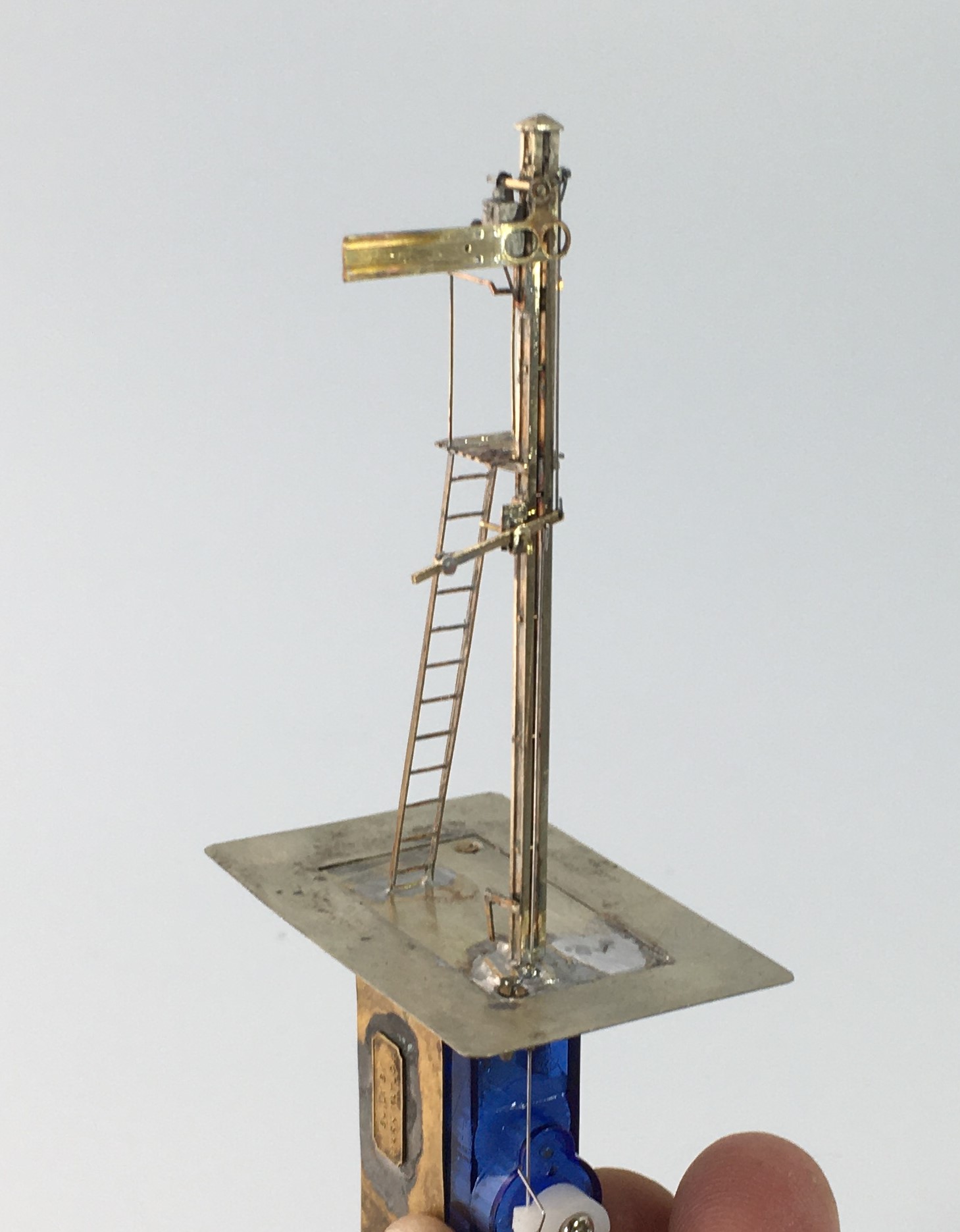
The base and mount for a two movement servo controlled signal
- Decide how you are going to operate the signal, how is the drive mechanism to be mounted and what does it need to be connected to mechanically/electrically;
- If you are going to illuminate your lamps, you need to decide how you are going to run the wires to the LEDs or fibre optic cable. It is possible to use the post as a common return but you still need one wireway;
- Consider how the movement is to be transmitted (especially bracket signals) and how you are going to replicate this? Multiple movements in close proximity to each other can lead to interference, compromises to reduce this risk are sometimes desirable (especially for triple or more movements in close proximity);
- Conceive how you are going to paint and assemble the signal before you start – it is generally easier to paint arms and ladders before you assemble them so it is possible to create sub-assemblies to be attached later – the touching in of local areas of damaged paint caused through assembly is a small price to pay for the ease of painting the remaining areas;
A Southern rail built home signal; the post was formed of two pieces of nickle silver rail.
Construction
- Tight, tight, tight – the most important part of building a signal is to keep all holes of operating parts as tight and snug as possible as slack leads to sloppy movement;
- You will use a lot of fine drills, down to 0.3mm, and a good quality pillar drill will mean you break rather fewer of them!
- Use the file up the length of the post not across it as much as possible – the files leave less scars and any that do occur mimic the grain of the wood;
- Pre-form or pre-drill elements such as balance weights, holes to the posts or landings early on before they are assembled when it is easiest (well potentially!);
- The prototype of most of the components to a signal are pretty delicate with fine sections; thus, to capture their character these needs to be similarly fine, however:
- There is a trade-off to make with the operating components such as balance levers which are typically best made over scale and with laminated brass to give them more strength;
- Generally, build the bigger more robust elements first and potentially alter the build sequence in the light of thermal mass and whether adjacent items might be disturbed by later additions – consider using different temperature solders and prefabrication of elements such as dolls with all of the lamps/landings finished;
A prefabricated doll and arm – I wouldn’t normally fit the arm until after painting but this is not true for slotted post signals
- Don’t use the flat etched ladders, they are too flexible to look real. Either use the built up versions or solder 0.3mm wire on both front and back of stringers and file the outside face flat – they look more realistic and are more durable.

A flat etched ladder with 0.3mm wire being soldered to the stringer
- Lots of delicate parts and complicated sections means that ultrasonic baths are really helpful for cleaning without damaging elements;
Slotted Post Signals
- Not the easiest because of the need to solder the arm to the spindle inside the slot. Use a laminated piece to the ear that is the point at which the operating rod attaches to the arm and extend it cross the back of the arm by 3mm so that it is would project beyond the slot slightly. Be liberal with the solder but make sure that the rubbing faces are cleared of any excess. Wrap the arm in cigarette paper and insert it into the slot. After the spindle has been inserted, touch the cigarette paper with light oil and allow it to soak through. Then put a little flux on the laminated ear and apply the iron. The heat will transmit along the solder joint and reach the spindle.
Operation
- Protect the signal from excess throw; they are delicate – therefore set the servo up to an approximate centre point through before connecting it to the model;
- Leave room to be able to see the signal as you are setting it up, otherwise it takes ages and a lot of bending under the baseboard;
- If you are going to illuminate your signal, understand what the right colours would be – oil lamps are relatively dim (so you need to resist down the voltage) and quite yellow (so modern LEDs need to toned down).
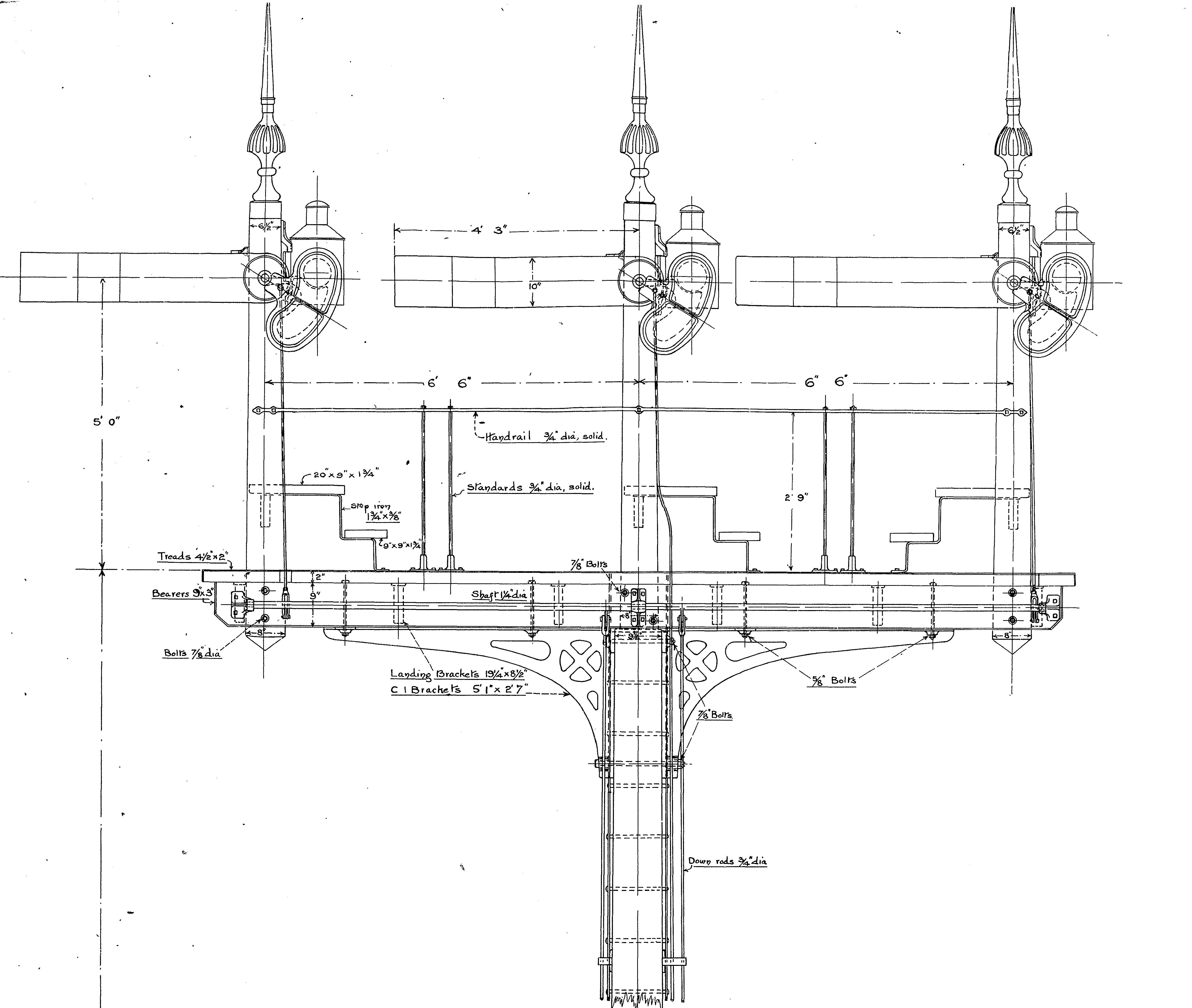
Dimensions
Dimensions were not standardised even within a company, let alone between, so offering directions on dimensions is dangerous – all I will say is these dimensions are commonplace:
- Single post wooden signals – 6” square at the top and then tapering out 3/16th of an inch for each foot of height (1.5% or so)
- Wooden doll posts – 7” square at top and tapering as before
- Main post for wooden bracket signals – 10” at the top and then tapering as before
- Single post tubular signals – 5 1/2″ to the upper portion and 6 1/2″ to the lower portion. The height of the lower portion varied with the height of the post (for details, see LMS journal no 4)
- Arm – centre pivot – 1′ 6″ from the top of the post; second arms 6′ 0″ below that;
- Spacing between dolls – 6′ 0″ or 6′ 6″ (less for shunt arms)
- Height of handrail to landings – 3′ 0″
A GER three doll bracket signal

Catching up on a Tennant
Way back in the mist of time (well 2016), I made a start on one of Arthur Kimber’s kits for a NER 2-4-0; termed a Tennant. After residing at the back of the cupboard for a bit too long (as is the way with my modelling, I do admire those that start something, see it neatly through to a finish before starting another……..!), I have made some more progress with it.
First up with the tender body which is close to finished except for some detailing around its front.
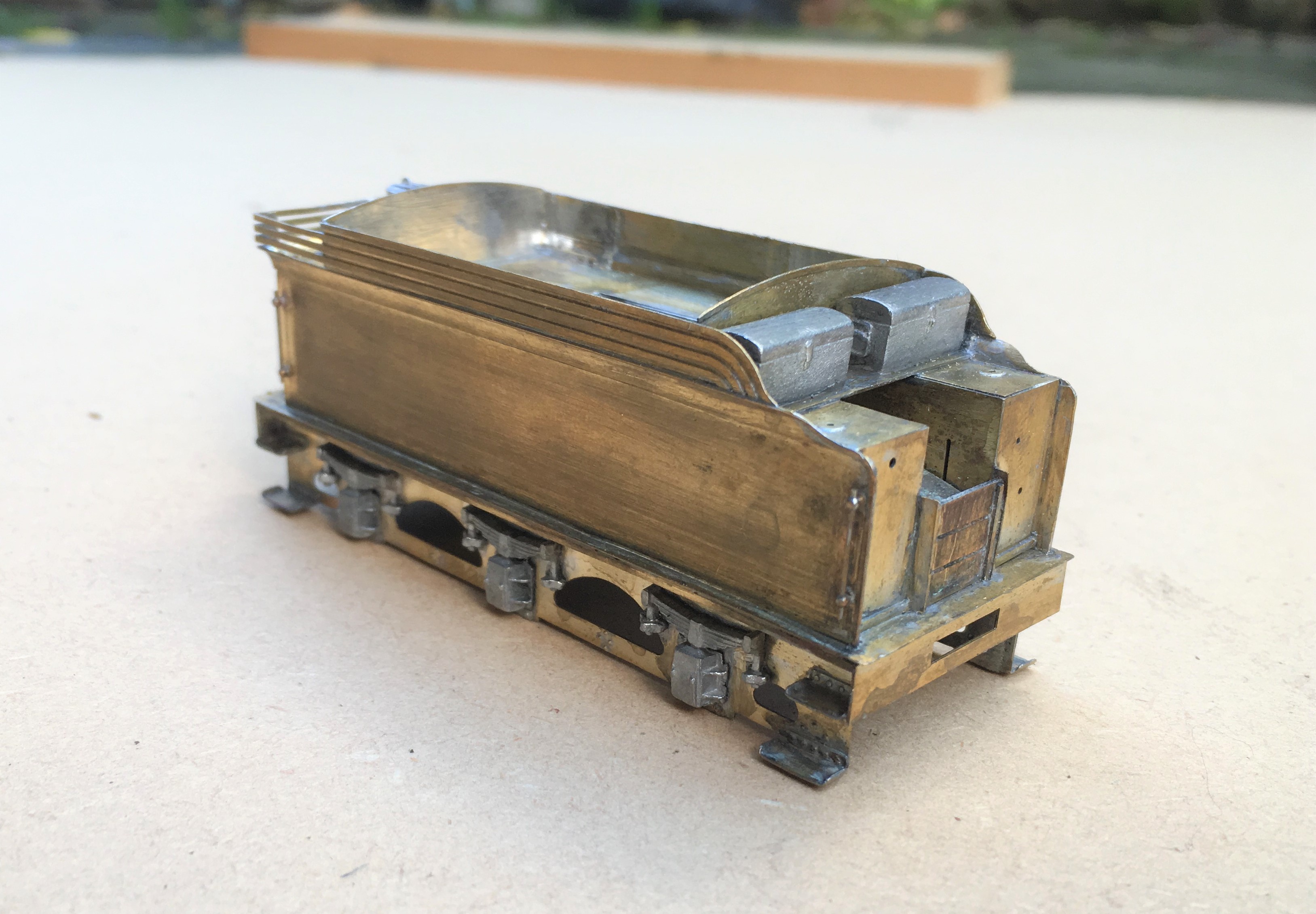
There was a bit of irritation in the building of this; despite being quite a modern kit the rear panel was much to narrow, the buffer beam a bit flimsy and there were some missing details around the front of the tender. Nothing someone raised on Jidenco’s kits can’t sort, but I rather hoped it wouldn’t happen with a modern design!
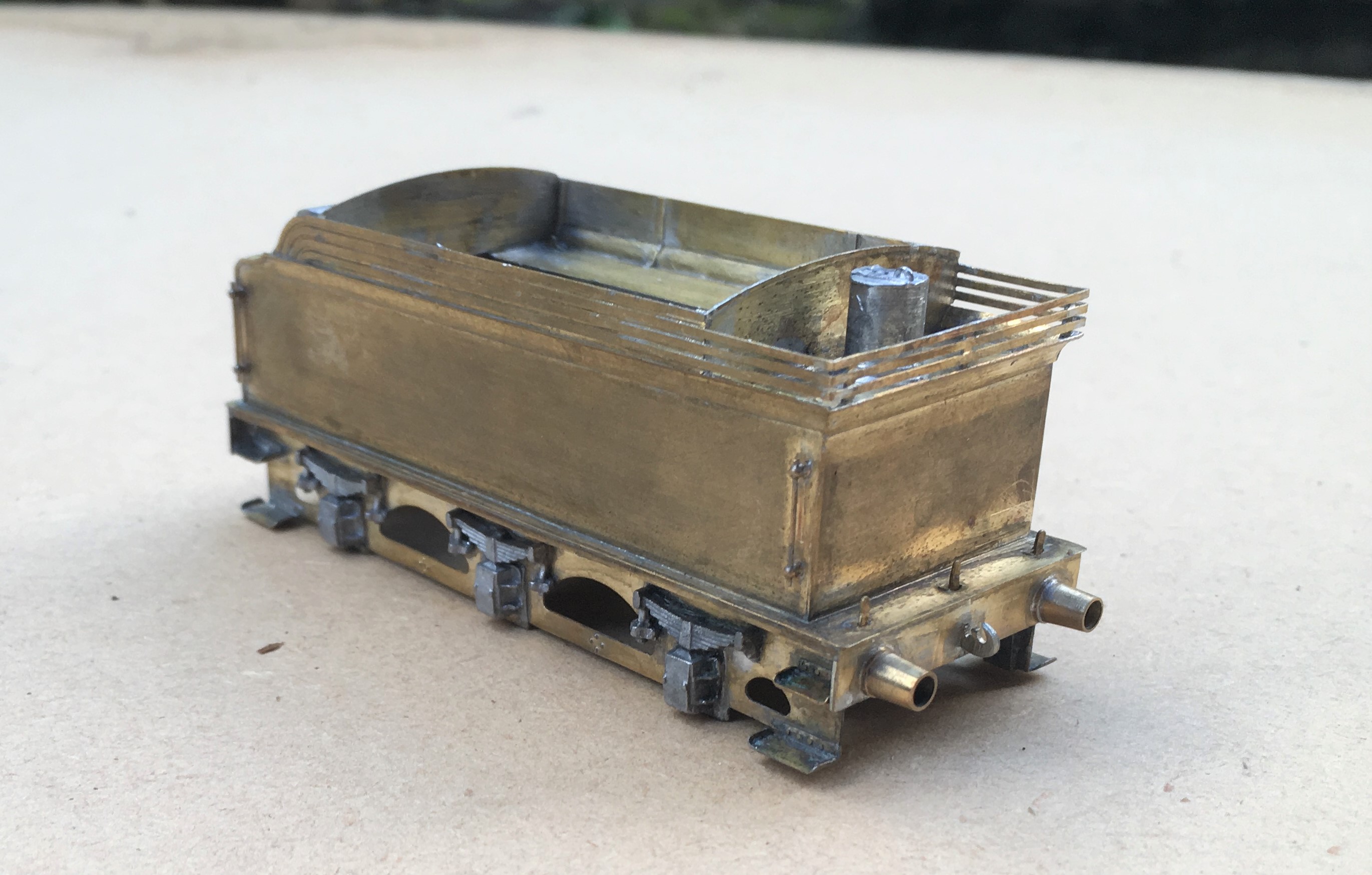
I also found that the boiler was about 0.7mm too long; a degree of filing and fettling has got it fitted. It is fair to say whilst there were these niggles, most of the rest of the kit is well designed and there are a number of neat facets to the kit, the flairs to the tender top for example are pre-rolled and they are very difficult to form without the right presses.
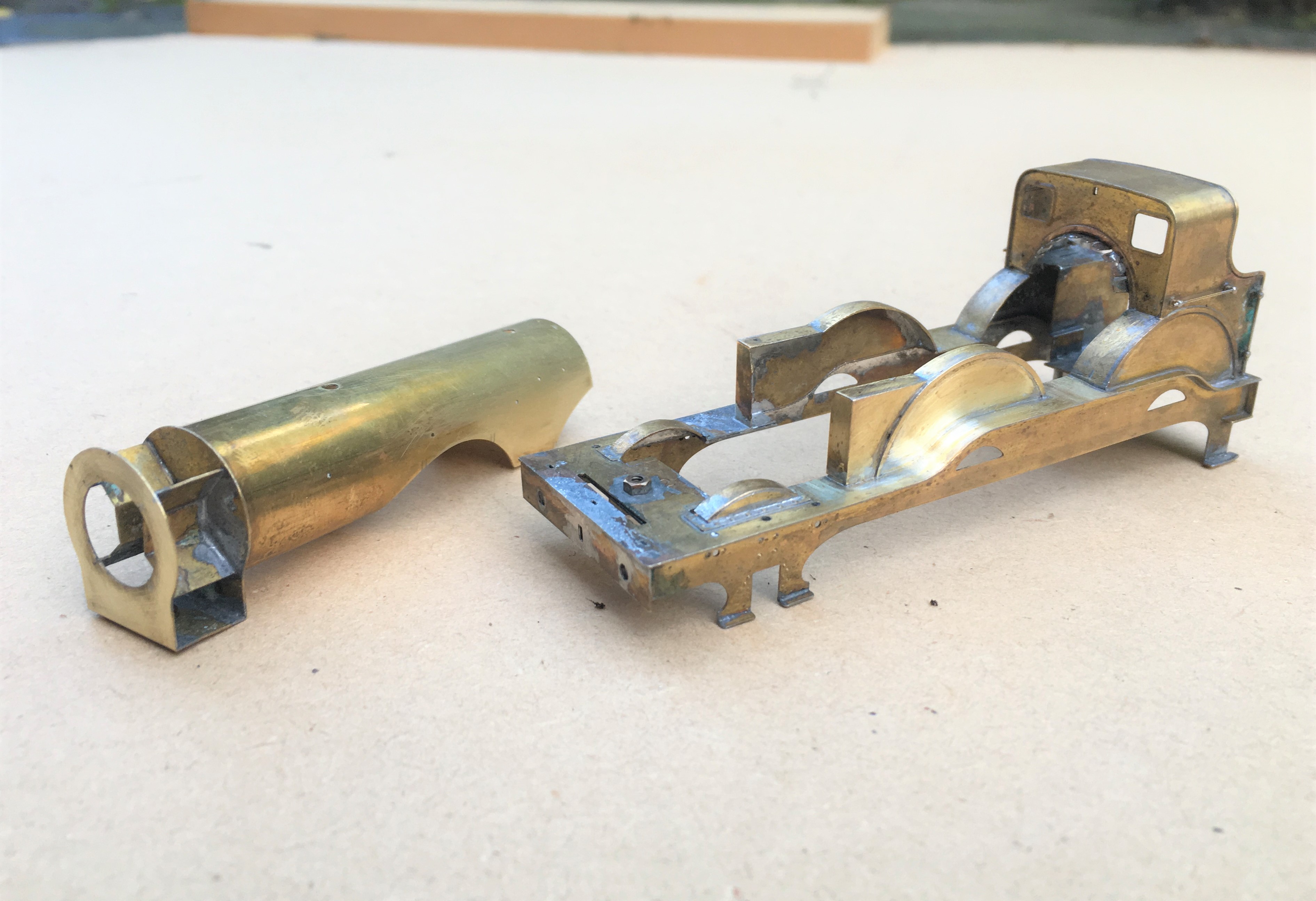
Here she is with the boiler now fitted and the first of the boiler fittings being attached. Something that grates with me on many people’s models is where these do not sit down tightly on the boiler or have overly thick flanges onto the boiler. Given that these are castings, it is understandable that these sometimes happen but they do damage the reality of the model and it pays to address these issues. For this reason, I prefer to solder them in place and am prepared to attack them with a file both before and after they have been fitted.
This does create a problem of soldering the parts in place; they are quite chunky so need a lot of heat to solder them in place and it is difficult to move them about to get them in the right place when they are so hot. I have just started to address this by drilling out the base of the boiler fitting and tapping it to take a 10BA bolt + washer. This allows the the fitting to be moved about until it is in the right place and held tight with the bolt so that it can then be soldered. I am pleased with this little trick; it definitely repays the effort and for the white metal castings, saves the risk of returning them to a blob of metal with too much heat!
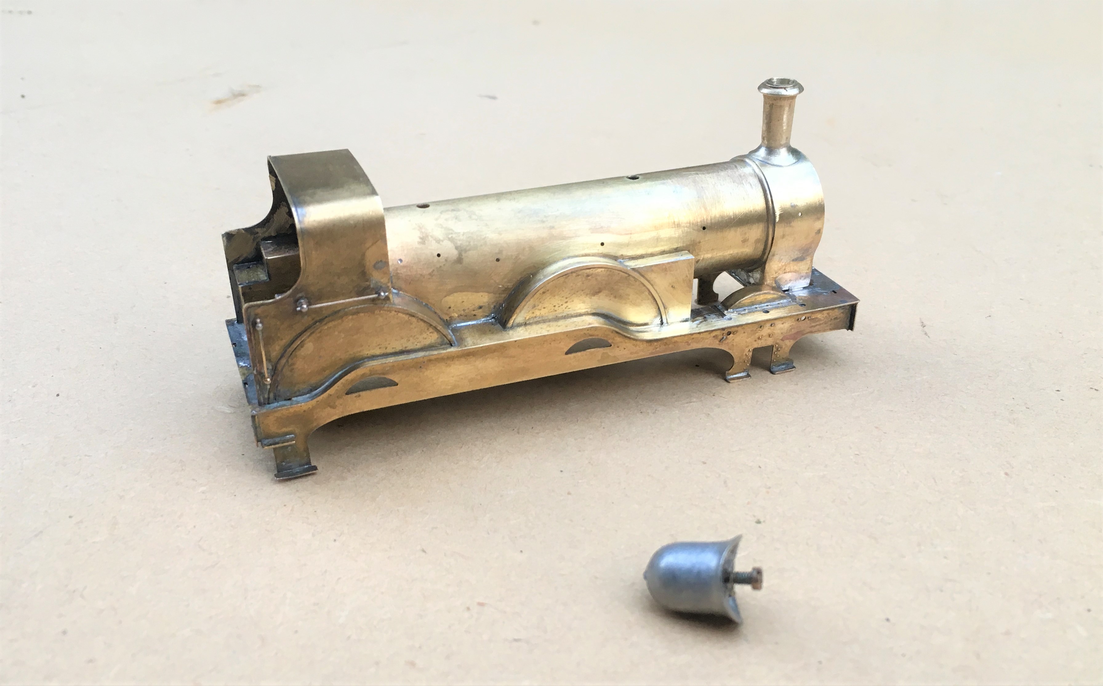
One example of a Tennant is preserved, being situated at the Head of Steam Museum at North Road Darlington Station. This has enabled me to take a good number of detailed shots but they are all rather close up they don’t really capture the prototype; so here is one from Neil Dimmer’s collection from the earlish 1920s, at (I think) York. The thin nature of the flanges to the dome and chimney I comment on above can be seen in this.
![[IMG]](https://photos.smugmug.com/LNERSteam/1884-NER-Henry-Tennant/Tennant-E5-NER-1463-2-4-0-Locomotives/i-L5bsMX9/1/794c2272/XL/1463%20Tennant%20E5%20%28NER%20%271463%27%29%202-4-0%20Locomotives-XL.jpg)
This view also illustrates how thin the boiler bands are. Given that this will be painted in NER livery that has lining on the boiler bands I am going to rely on the thickness of the lining transfer to give the impression of the boiler band rather than represent them in metal.

News from Miscellany Models
Followers of this blog will have noted that various test builds of my artwork coming together and I am now able to offer a number of these for sale under the name of Miscellany Models.
First up is a Highland Railway/LMS/BR diagram 51 full brake – priced at £48.00 for a 4mm and is suitable for OO, EM or P4. These were the last generation of full brake produced by the Highland, built with both cupboard doors and sliding doors as well as alternative forms of guards duckets (all of these are included in the kit). The kit inclusive of fully sprung Fox bogies (see below), roof, corridor connections (also see below) but all castings and buffers will need to be sourced separately. The castings for the bogies are proposed, but are not presently available.
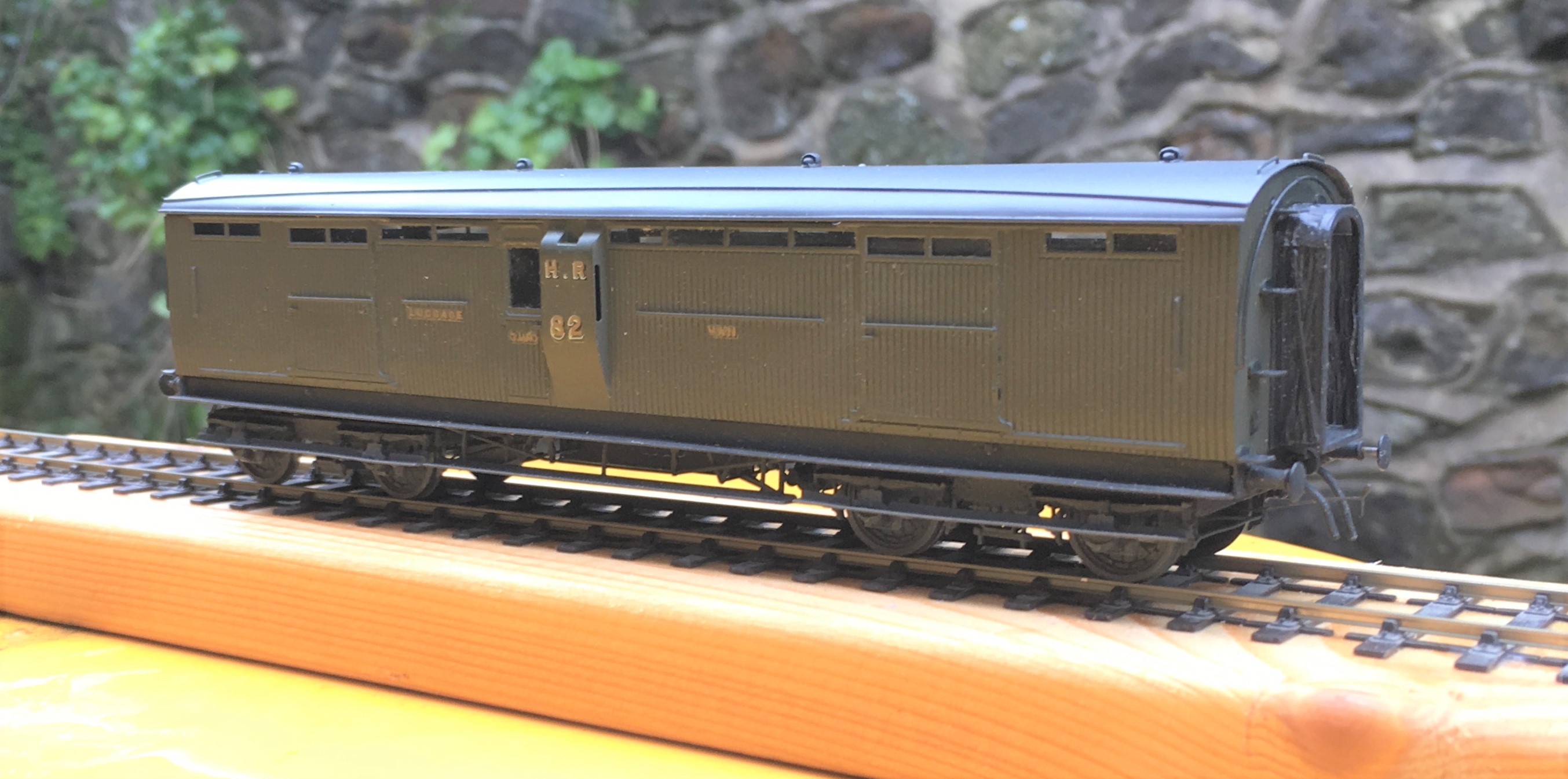
As was common with many pre-grouping coaches these vehicles utilised Fox Bogies (£16.00) and these are being made separately to the remainder of the kit, These bogies have been developed in conjunction with Justin at Rumney Models and are fully sprung, with both the axleboxes and the bolsters sprung. They really do glide across track and look as if they weigh many tons rather than a few grams! They need castings for your favoured axleboxes/springs and bolsters but do include the foot steps and all of the bogies sides, brakes and details. Suitable for oo, EM and P4.
.JPG.3b26712c4490ad68695b10226612a0a9.JPG)
The second coach kit is for a MR/LMS/BR: Dia 530 Passenger Brake – priced at £36.00 in 4mm scale (suitable for OO, EM and P4). This prototype was built in some numbers and by the 1920s they were spread extensively across the LMS system. The kit is for full etches covering the roof, body, underframe and footboards plus parts for the sliding central axle included. It needs axlebox/springs (available from Branchlines or Coopercraft), gas lamps, buffers, brake and gas cylinders.
.JPG.1678157932a192d68328755d825c54f0.JPG)
On the wagon front, there is an etch to detail the NER/LNER/BR: Dia P7 Hopper Wagon – £13.50 4mm (sufficient for two wagons). They cater for a large number of the variants to this numerous and long lasting hopper wagon. Needs wheels and the Slaters kit P7 kit for the donor model. Variants that can be made include the end braked version, improved components for the Morton braked version, outside twin W irons and also the anti-friction wheel device.

All of these are available from my website https://miscellanymodels.com/ and in addition to this from the Rumney Models stand at the following shows – Scalefour North in April, Railex in May, Scalefourum in September and South Hants in November,
All of these have been extensively road tested by me with a couple of test builds for each of them. You can see this unfold on my blog and if you are interested in seeing how they go together do take a look!
Please remember that the availability of these models is an adjunct to my own hobby and this has to be accommodated within the constraints of my day job and general life! In particular I can’t get to post these orders until Saturdays so do please give me a little slack when it comes to getting the goods to you!

One for the Paintshop
I am sure I am not alone in having in mind a list of modelling jobs to do over the Christmas break and to find that the bulk of the list remains uncompleted when it is time to go back to work!!
One item on my list was to finish a North Eastern Railway autocoach that I have had underway for a while and that at least has got itself off the list!
The bulk of this is from a D&S etched kit which I have seriously devalued by opening the box!! I have replaced the fixed bogies with some test build sprung bogies that I have had under development for rather too long now (they are finished, but for the castings which I need now to produce following the demise of Lochgorm Models for at least the time being).
I also replaced the roof with some metal sheet rolled to the curves. This proved a real challenge and took more than one attempt as I found you could not roll the section with the holes for the clerestory already cut as the bend all occurred at this weakened point. I also took the effort to put on the gas lines with fine wire as I think these add so much to a model of this era.
I think they are very attractive coaches but there is a problem with them – they tended to go in pairs so I have another to build! Just not quite yet! Fortunately, the BPT is not down to me, but I think you may find yourself under pressure soon John!!!!

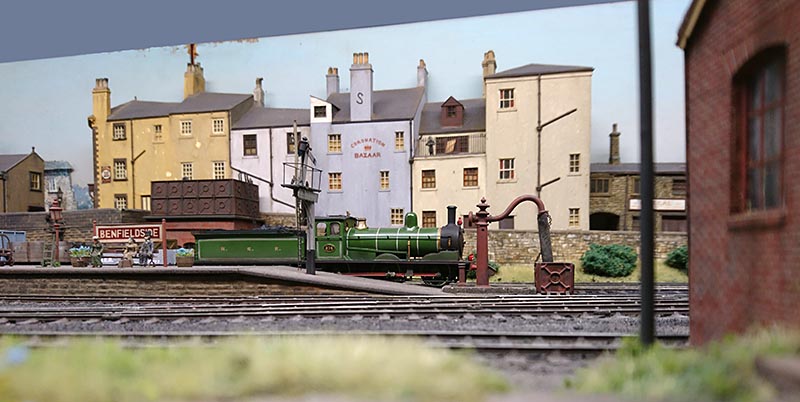
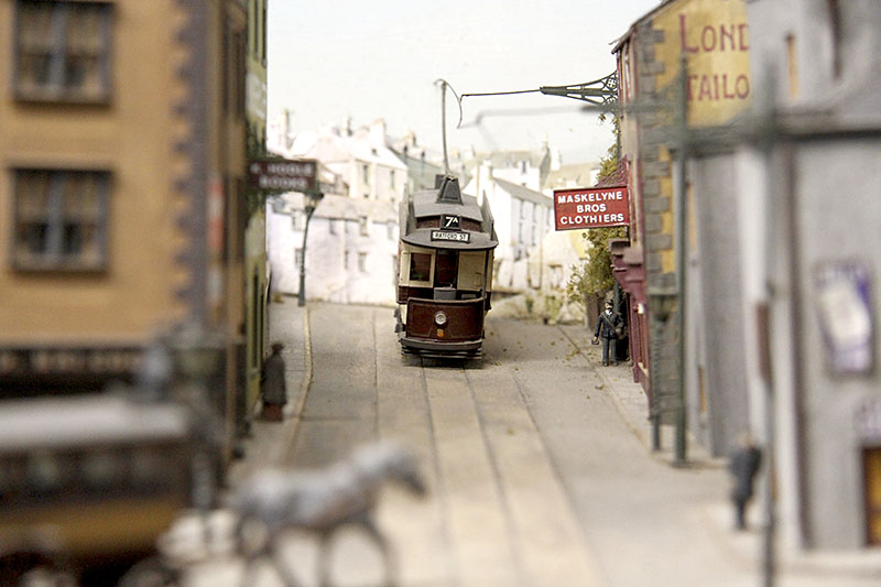
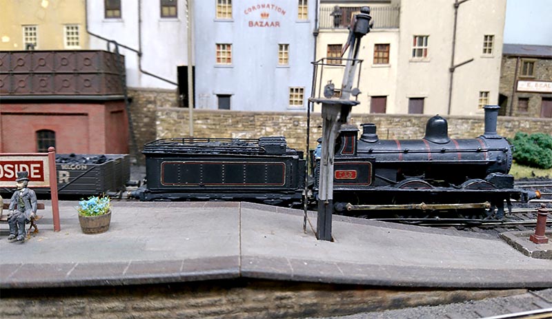
Benfieldside at South Hants – Part 2
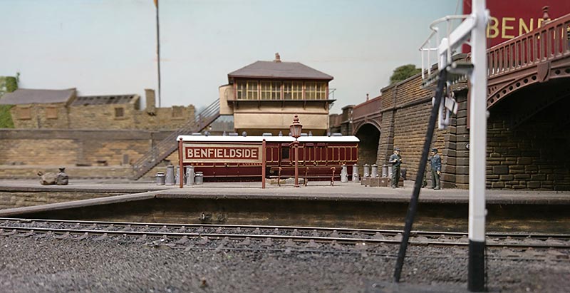
Following from last week’s post, here are a selection of further photographs from Benfieldside’s outing at the South Hants show, starting with a few around the platforms.
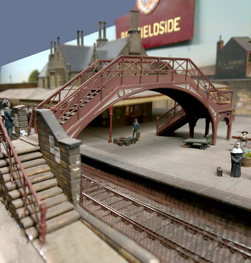
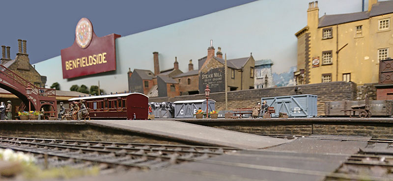
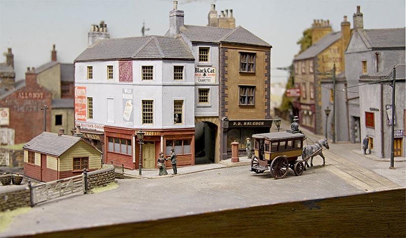
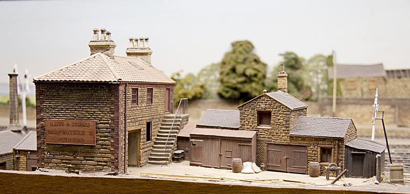
One of the charms of the layout are its buildings; typically constructed from cereal packets – good old fashioned modelling but very effective as you can see!
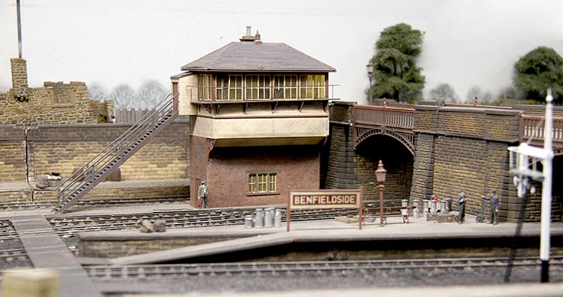
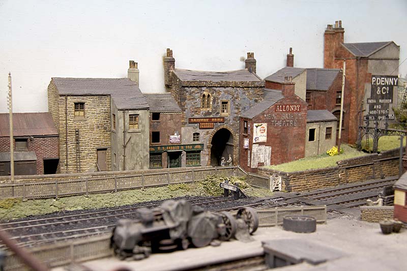
There remains a lot of stock to build for the layout and also a fair amount of restoration; the next bit of restoration can be seen in the picture below; a somewhat wonky signal (which will be rebuilt as a two doll to act as a starter signal for both the bay and the main loop). Hopefully, this will be done for ExpoEM, which is the layout’s next outing – see you there?
Many thanks to Dave Brandreth for the photographs in this post, along with some of those in its predecessor.
