Blog Archives

At last, a Finished Signal!
Well, that took a while longer to make than I had hoped! Not least because it is not the only signal I am working on at the moment.
Although the drawing did not show a landing in front of the balance weights, i felt that it was likely one would be provided given that these need maintenance at times. Hence this was formed from some L section and an etched slats and provides a useful point to secure the ladder too.
The issue with signals with dolls is that each doll is in effect its own signal; it has a ladder, arm and lamp assembly. But worse than this is that it is also necessary to get the movement to transfer over to the doll so there is even more than a seperate signal per doll. There are a number of ways the prototype used to get the movement to transfer and in this case the signal uses L shaped elbows. Sadly these are more challenging to make as there are more working components and to be prototypical they out to be little more than a couple of mm in size.
A key trick in making signals is to spray paint as much of the signal as possible. Because the components are generally fine any excess thickness of paint will quickly make the modelling crude. As a result of this, I now generally try to make the ladders detachable. In this case there is a rod attached to the top of the doll that a tube at the top of the ladder slips over, with prongs at the base.
So here it is a finished (except for a tie rod which I fortgot to paint so is to be fitted shortly).
And as is de rigeur for a blog post on the building of signals, here is a video of it in operation.
")
More Seasons Greetings (and Signals)
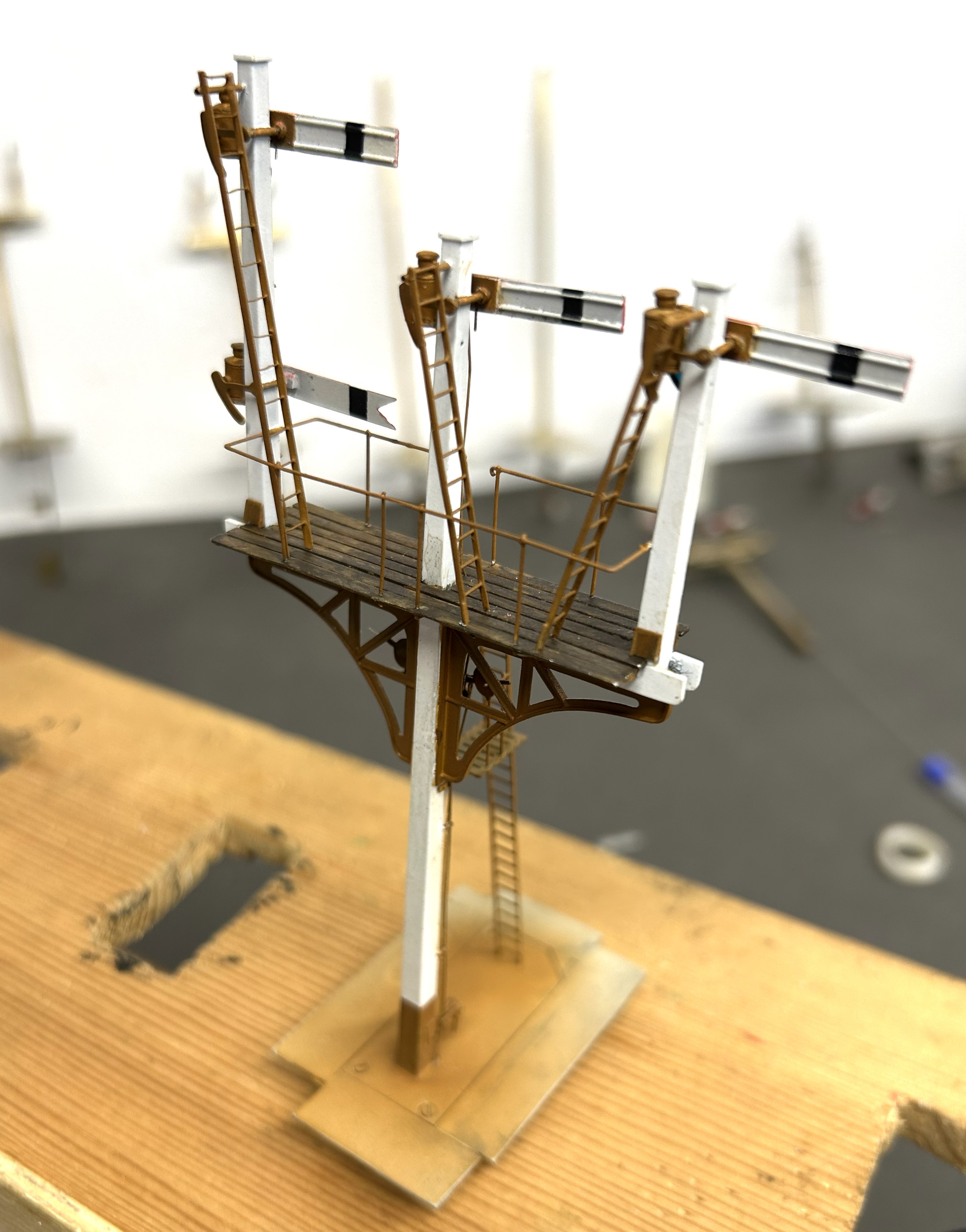
Having got the post and dolls in place, the next step was to fit the brackets.
The LNWR were unusual in not using cast brackets; instead they fabricated theirs from sheet and angle iron. Those supplied by MSE are a flat etch and therefore feel a bit one dimensional.
I therefore sweated on brass wire to one side of the strutts on both faces and also a plate on its outer edge. This helps give this a third dimension that was lacking before.

The next issue to be confronted was the landing where the MSE etch only provides a landing to the rear of the posts whereas this (and it appears many other LNWR signals) have landings both sides. I therefore had to produce support brackets and an enlarged area of landing. Foolishly, I forgot to drill holes for the guard rails before assembly, which meant that i had drill them in-situ. This is awkward due to the proximity of the dolls – it cost a couple of drill bits as a result and as a useful reminder to get it right next time!
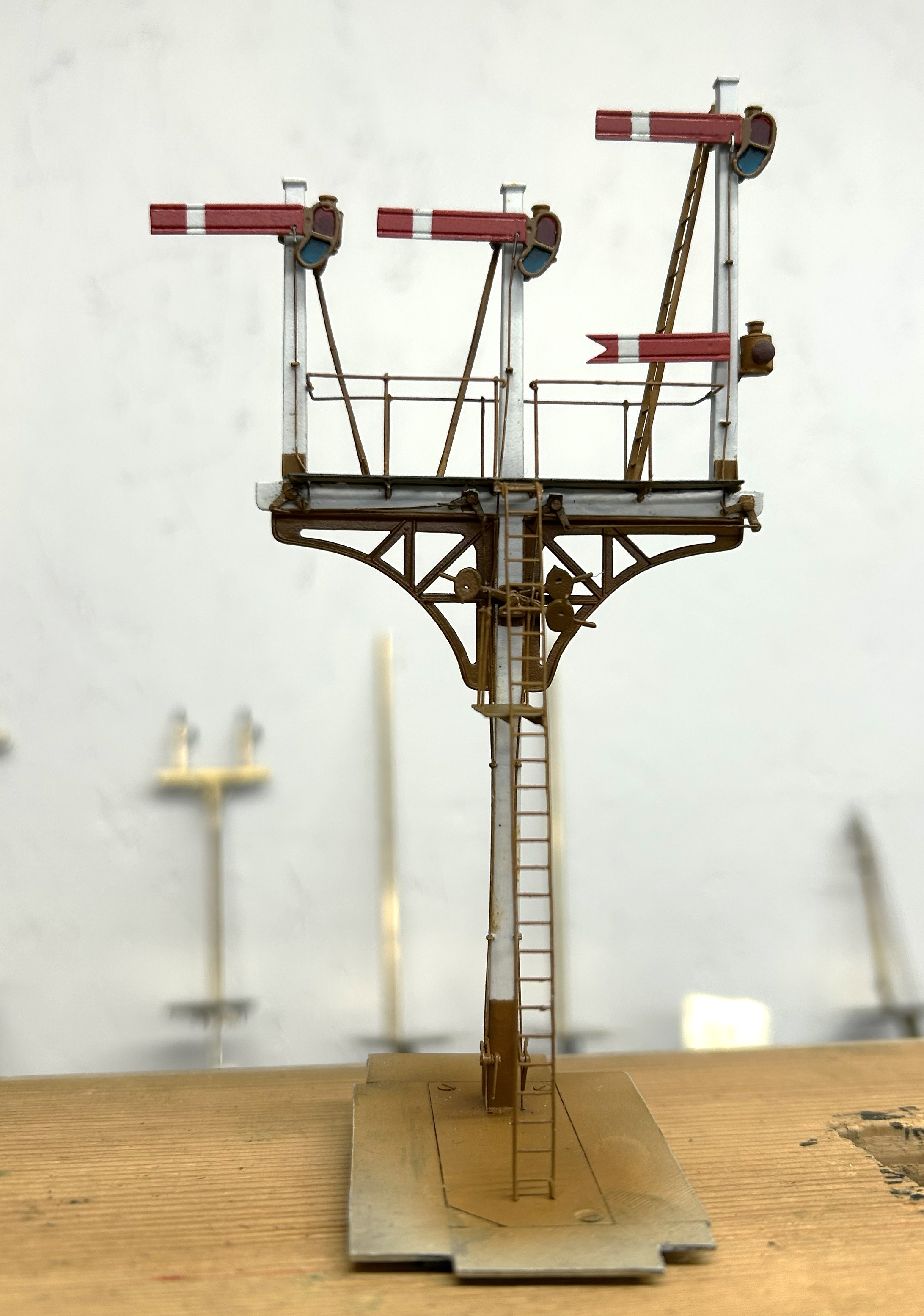
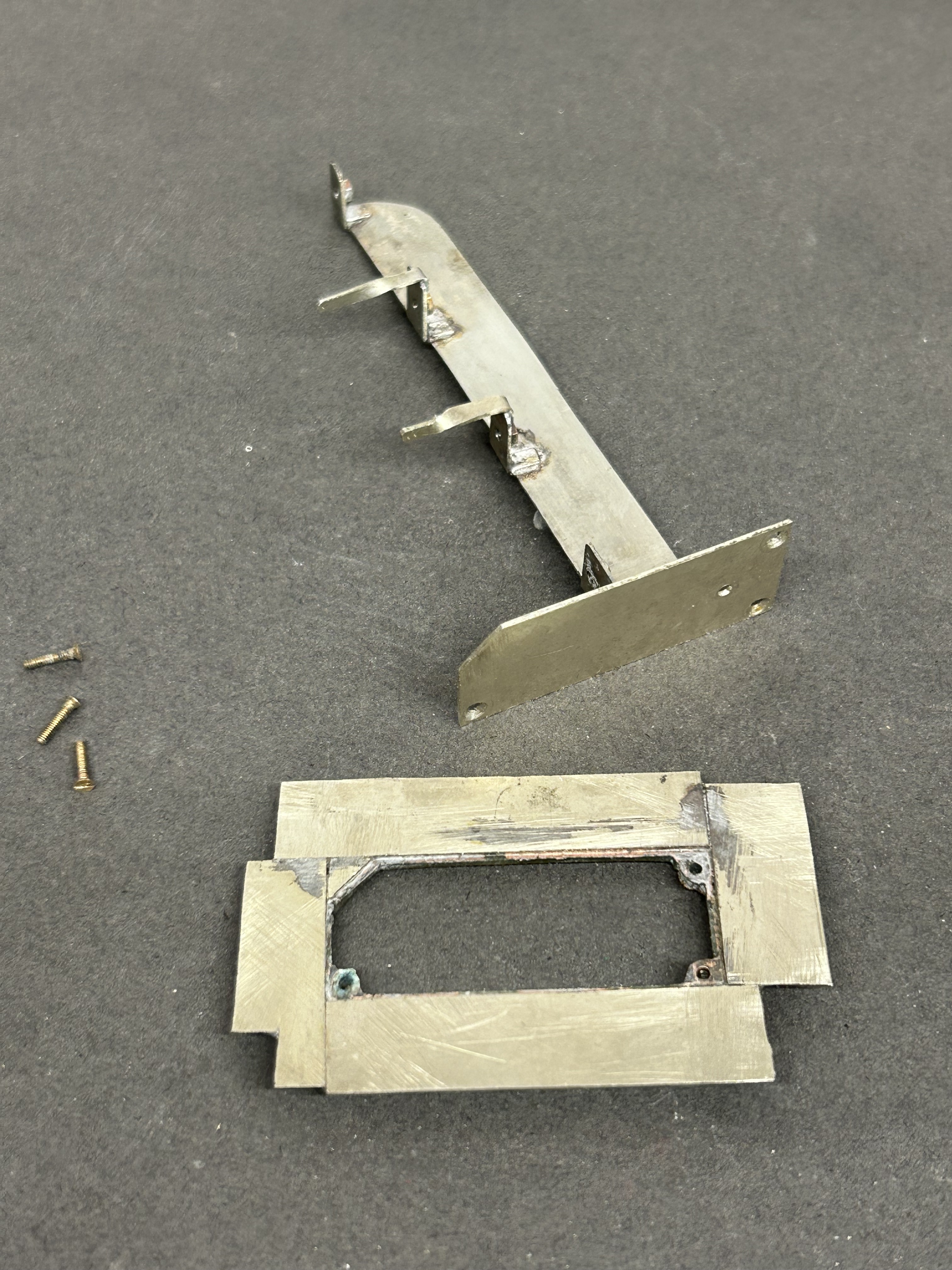
Next, I diverted my attention to the the mount for the servos. I now always form these with a lower base which is permenantly attached to the baseboard and into which a second detachable base plate is inserted. The two are a tight fit such that once a little scenary is applied to the top, the joint is invisible. These are secured together with 12BA screws to allow it to be detached both during the build and for maintenance but generally it is secured in place. This is because signals are prone to damage when being moved about and would need recommissioning to get the movement correct each time they are reinstated.
I drilled the underside of the post and tapped it 10BA in order to hold it in place. This enables me to secure it onto the base but subsequently remove it as I build it. I do solder it in place at the end of the build, but the ability to remove it during the build is helpful. The fact that the bolt holds it in place also makes it easier to get the post vertical, rather than trying to hold it vertical simultaneously with the soldering.
Whilst MSE do provide a white metal casting for the finials, I opted to fashion my own with brass as I find them crisper. To ensure these do not fall away as later tasks are completed, I use a high melting point solder for these and also include a pin drilled into the top of the post. Lamp brackets, lamps, the balance weight mount and some supports for the ladders were next.
I now have a recognisably signal beginning to form but the difficult bit, the movements are still to go.

Sam’s Trains – HR Open Wagon in 4mm/1ft
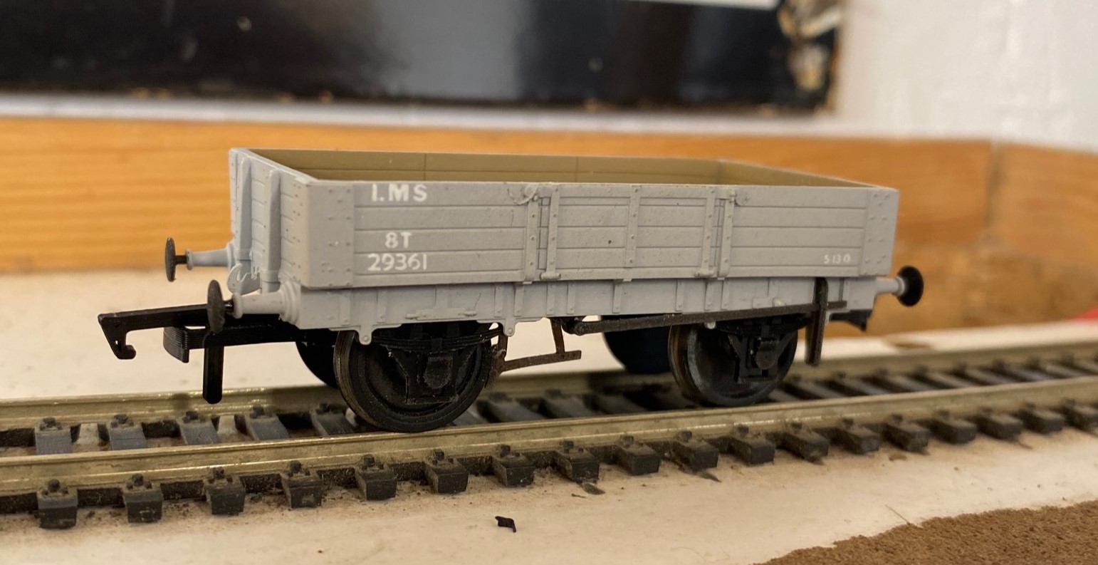
Somewhat out of the blue, I was bombarded by adverts for Etsy for something that I actually might buy (who knew that was even possible?). This was a small batch production of a HR wagon apparently being marketed as an ideal accompaniment to the Rapido’s Jones Goods. The pictures in the adverts suggested that it had captured something of the character of a highland wagon, so I allowed my loyalty to all things Highland to take a hold and I parted with £25 to see what it was like.
Sam is a youtuber who has created a niche for himself by producing caustic and generally very critical reviews of manufacturer’s products to gain views. How he has not been sued for libel for producing this clickbait I do not know, as a number of manufacturers must have thought about it given what he says about their products. As a result this, it is fair to say I was pretty concerned about what I might get – my conclusion is somewhere in the middle, some good points but there are plenty of errors too.
The model is of a Jones era open merchandise wagon to diagram 19. There are insufficient records to confirm when the prototypes were in production but probably in the 1880s upto the latter part of the 1890s. Similarly, withdrawal dates are unknown but it is probable that they lingered to the LMS era, but probably not by much. It was designed to be used for a variety of merchandise, often below a tarpaulin, but might well have been pressed into the carriage of minerals or even fish. Certainly, they were used for transporting sheep which was a seasonal (and substantial) traffic for the Highland. When used thus, they would be fitted with flakes to provide a higher fence to reduce the sheep suicide rate caused by jumping from moving trains.
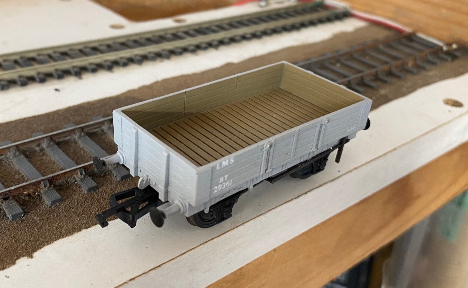
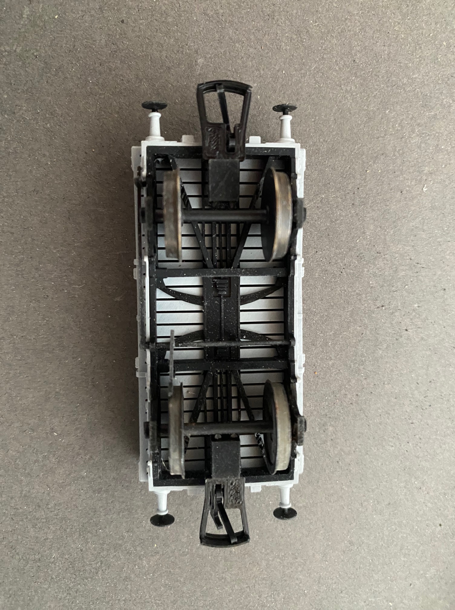
The model is 3-D printed from resin and the quality of the printing is surprisingly good with almost no stratification lines. The resin seems to have some flex to it so ought to be durable and the wheels run relatively freely in the bearings. The resin appears to be self-coloured, with the chassis being in black and the body the intended livery (mine was in grey but there is a red oxide colour for the highland livery versions). This had led to some errors of colouring in that the trunnions and couplings should be black and the grey is too light as well as needing a bit of green to be a match for LMS grey. However, the lettering livery selected is the later LMS livery with small branding suitable from 1936 and is not strictly speaking correct even then as it has the wrong layout and an impossible wagon number. To be fair to Sam, he admits this is a “what if” prospect so if this floats your boat so be it.
The principal dimensions of the model are generally good; except for one important point. Jones era wagons used 3’7” wheels and this is fitted with 3’2” wheels. One of the implications of this is that the buffer height is too low but fitting the correct sized wheels does correct this. Swapping the wheels as an OO modeller you will need a trim of the framing on the underside to allow the flanges clearance to turn and all 4mm modellers will find that the brake block fouls the wheels and has to be replaced – or as i did softened with the heat of a soldering iron and bent back. The correct wheels should be split spoke and whilst these are available from the r-t-r manufactures in the smaller size, I don’t think they do them in 3’7” so you Gibson wheels are your best bet. The impact of the larger wheels is quite striking; they look rather quaint and from a time past compared to what is generally available to the modeller – but then again, that is exactly what they are!
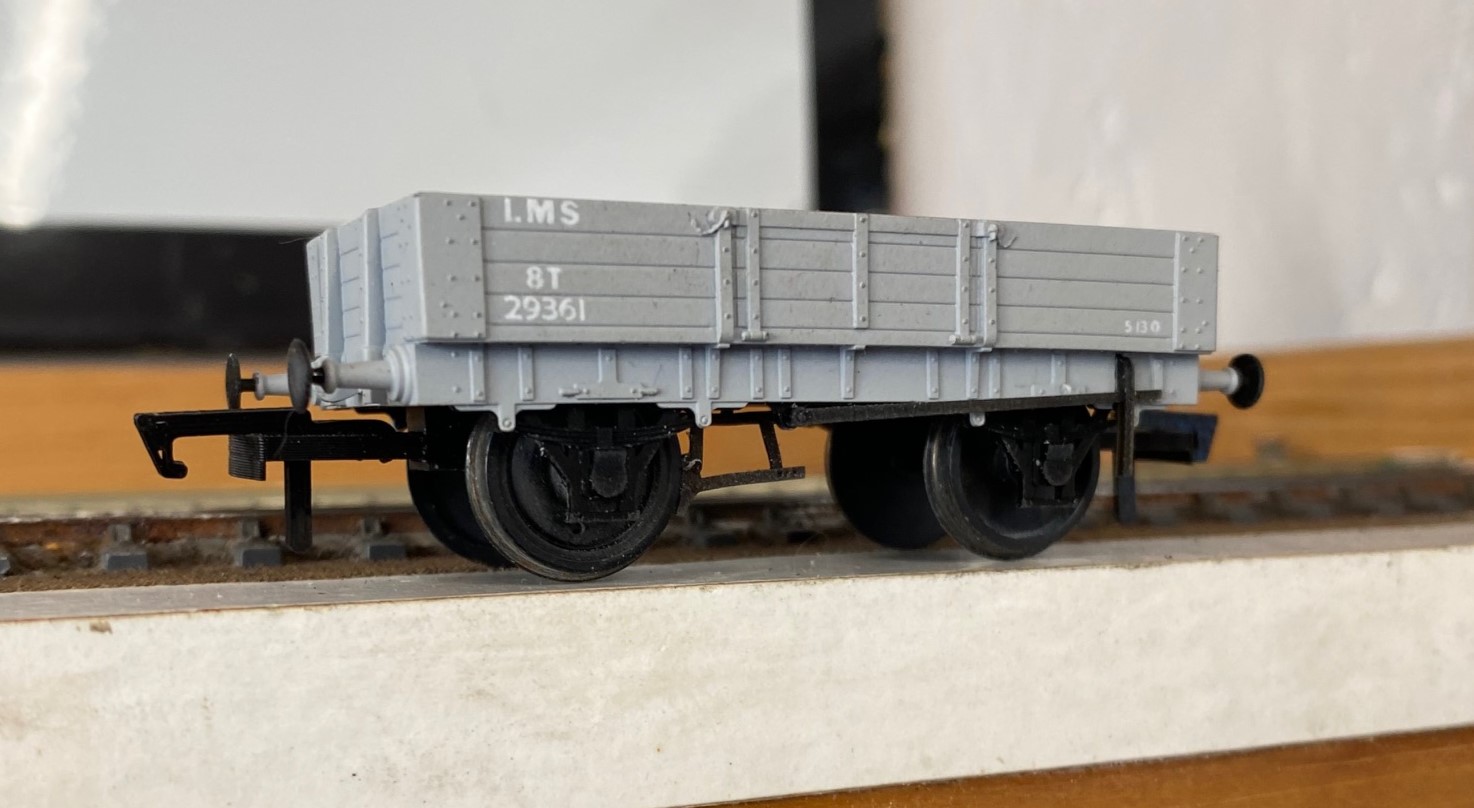
Most of the detailing is crisp and fine, but in some respects too fine such as the brake block. Conversely the body sides are too thick – possibly a compromise to make the model more durable or easier to produce – but never the less it makes the wagon a bit clunky. The buffers are separate and it looks quite realistic to convert them to sprung buffers if desired. The model comes with safety chains which are very nicely made but these would only have used early in the wagon’s life so the fixing holes need infilling for any modellers from the turn of the 19th century onwards. The trunnions also seem to be overly wide and the operating rod for the brake pivot has been extended to the blind side of the wagon for some reason – so a little surgery is thus required.
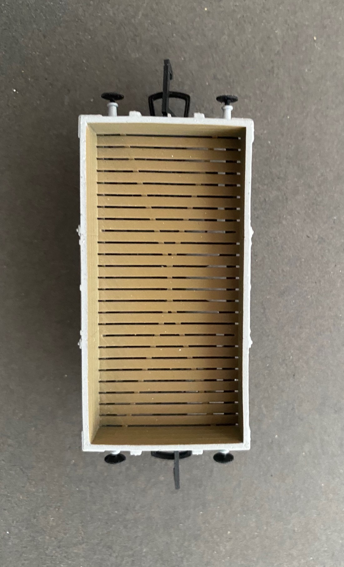
My model was bowed, with the high point to the middle of the wagon – whilst many wagons did bow over life, it would normally be the other way with a sag in the middle. This is likely to be a function of the manufacturing process – I suspect that putting it in very hot water will soften the resin and allow the bow to be corrected. What will not correct with hot water is the rather odd slatted floor – not sure where this comes from as there will have been no desire to deposit the commercial material on the track! A new plasticard floor is thus required. Less easy to fix will be the axlebox / springs which are significantly undernourished but are integral with the W irons so adjusting these will require the use of etched W irons and then castings if you can source these.
It is likely that this model is intended for customers who just want something “Highland” to go with their Jones Goods’ and for whom these errors are not going to be important. Against this criteria, the model is acceptable and if this promotes a bit more interest in the Highland Railway, this is fine with me.
However, if you want a more accurate model then the list of things to be attended to is not inconsiderable and as the joke goes, if i wanted to get to there, i wouldn’t be starting from here! I will be putting mine on ebay before too long is perhaps the most succinct conclusion I can offer!
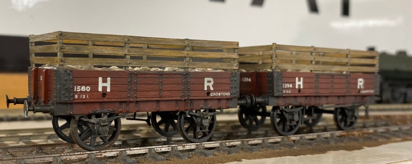
A pair of rather nicer dia 19 open wagons; this time fitted with raves for sheep traffic bult by Ian Terrell from Mircrorail kits. Whilst the origins of the kit will go back at least 40 years, they do look crisper than the Sams Trains version.
The Colour Red – or the Quest for LMS Crimson Lake
A topic that comes around from time to time, including to my lips, is what colour exactly is Crimson Lake? I thought that my analysis and that of others that have contributed to the discussions were worth sharing more widely; so here goes……….
The Historical Context
The first good insight I have is from George Dow who was a prolific author of the 1960s and 1970s, including on liveries who wrote in the Railway Modeller in 1973:
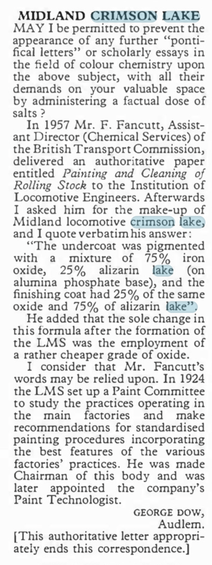
However authorative this is, fifty years later, with the change from natural to synthetic pigments this is not of great help. Also B&Q do not stock alizarin lake last time I looked as it is a pigment produced from a complicated processing of a vegetable and is probably fairly inconsistant anyway. https://www.winsornewton.com/row/articles/colours/spotlight-on-ruby-madder-alizarin/).
The Problem With Reds
Many years ago, when I was still in my shorts, I worked in a printing ink manufacturering business and red was one of our bugbears. This was for three reasons; as a colour it is less opaque than many colours so were prone to poor coverage, it is also prone to fading and like all paints, it is affected by the surface treatments, in our case varnishes. All of these issues affect how Crimson Lake appears on both the prototype and our models.
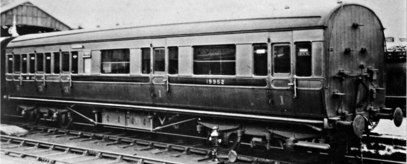
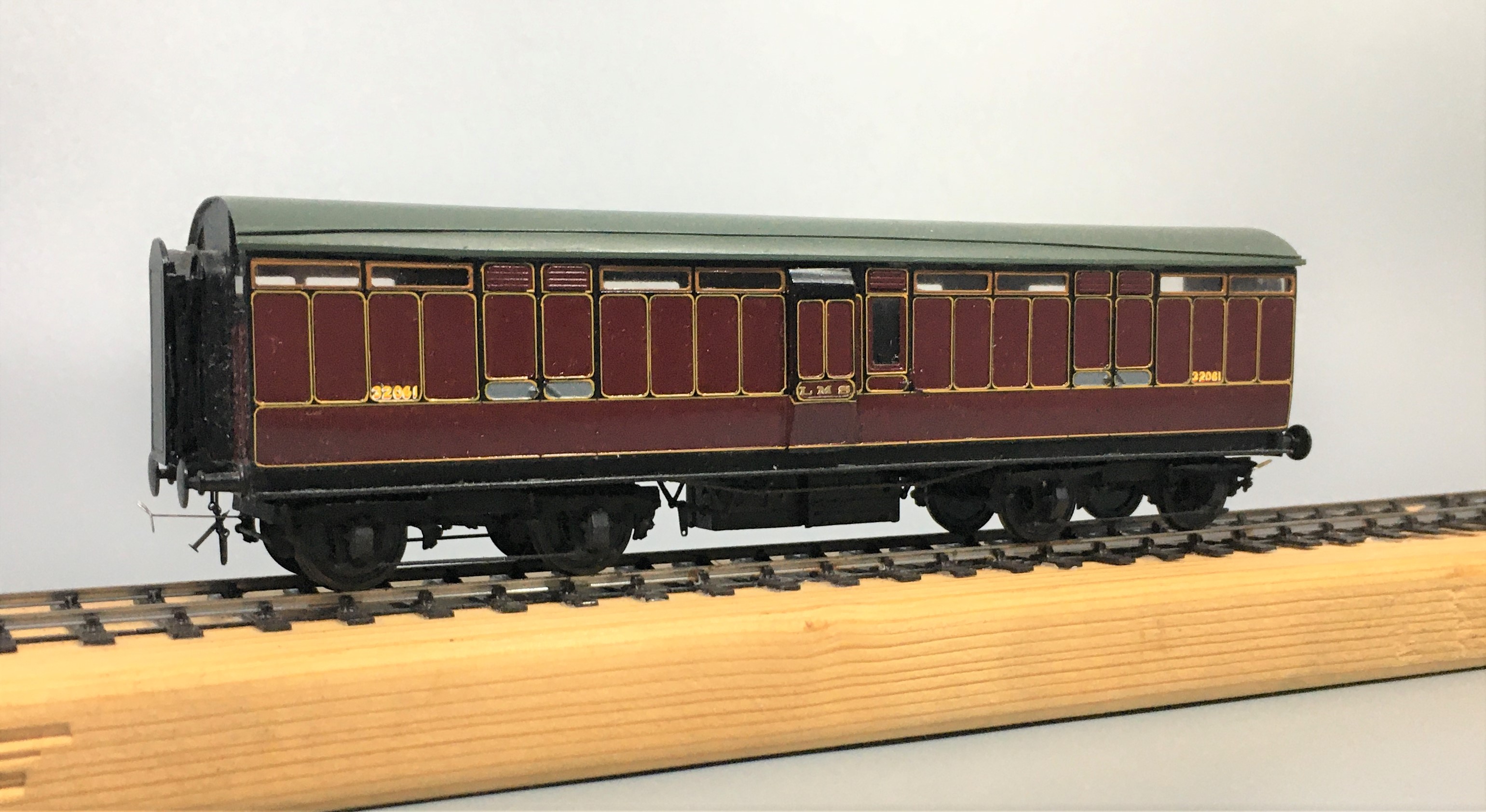
A Caledonian diagram 106 non-corridor composite shortly after being renumbered to 19952. This appears to have been acheived by painting over the predecessor number and then the application of the fresh number and then varnishing. The patches that have been so treated stare at you somewhat and ilustrate how the paint and lustre deteriorate! Photo by H.R. Norman ref 6081 and now in the NRM
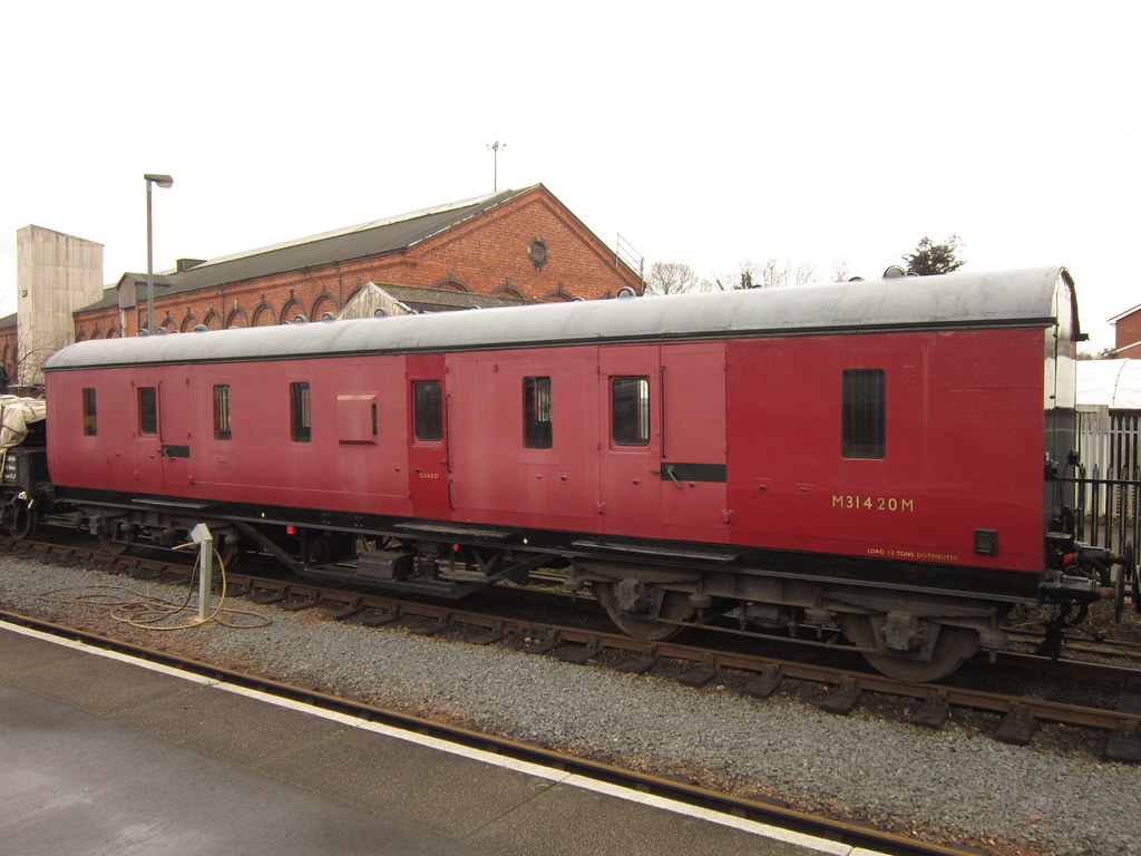
Its still a problem now too as this diagram 2171 full brake at Kidderminister shows. Photo SVR Enthusiast via Flickr
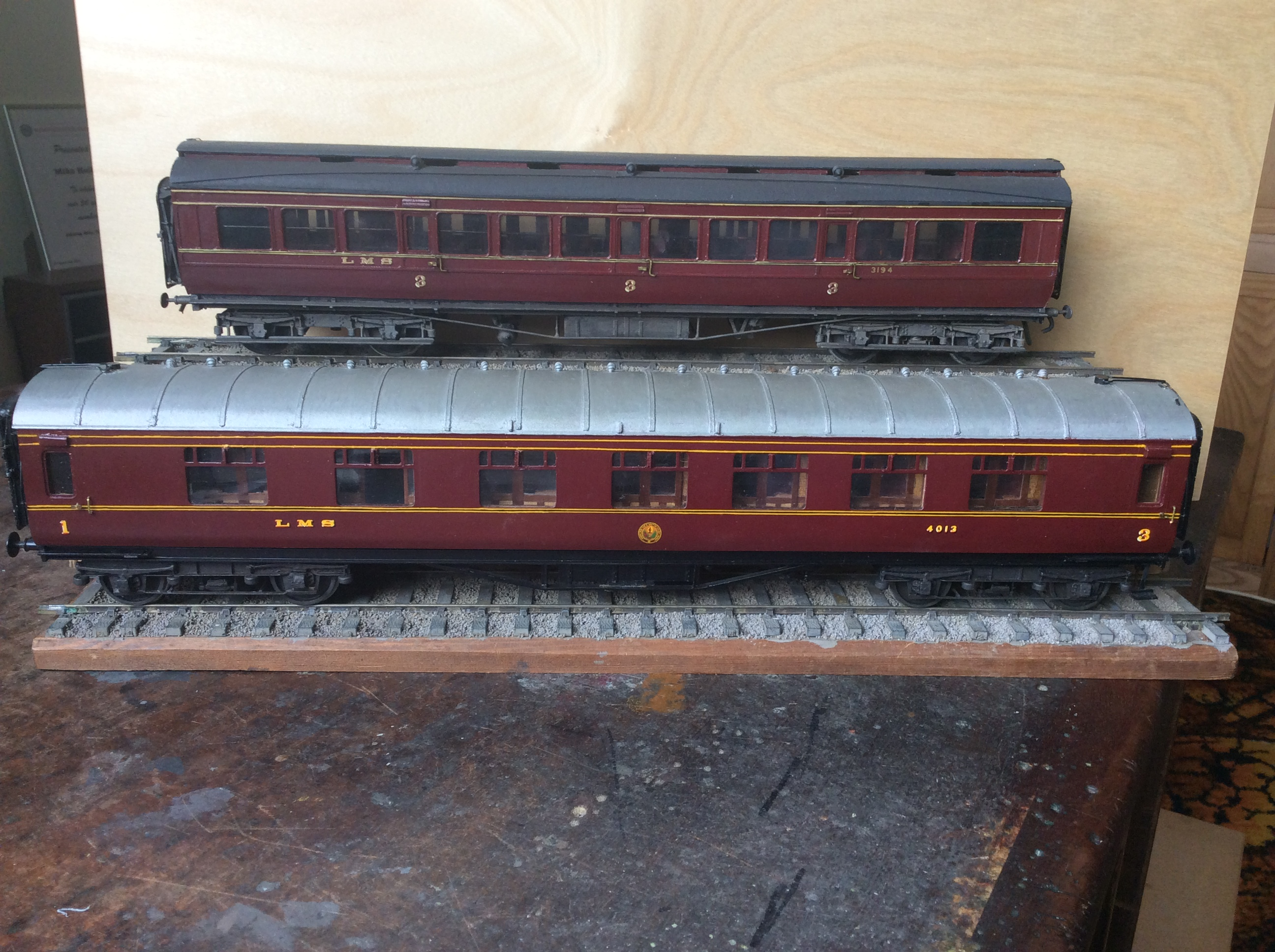
Both of these coaches have been painted in the same top coat, Precision Paints LMS Crimson Lake. The top coach, the clerstorey, followed the paint sequence noted by George Dow above – a first undercoat of LMS wagon grey, followed in turn by 75% grey, 25% crimson; 50% each; 25% grey, 75% crimson and finally 100% crimson. On the lower coach, the crimson was neat and painted over an undercoat of LNER bauxite. Both were painted at the same time, in otherwise the same manner and in both cases they were varnished but not weathered. The difference is startling! Photo and models by John Hastings Thompson.
Does Colour Scale
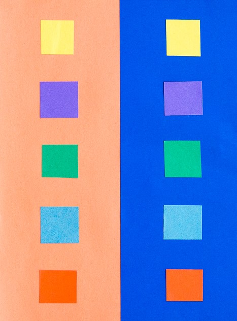
Like weight, I am not convinced that colour scales or perhaps it does but given that our models are smaller than the prototype it is more heavily heavily by contrast. I am sure we all know about the optical illusion causing the viewer to read differnt colours of the same sample by virtue of the background – is this happening to us as we perceive the colour of a model? Try the sampel from the Exploratoium below:
The presence of lining is also a major influence of the feel of the colour. The gold and black of the LMS seems to add a bit of sparkle and depth of colour to the red.
It was a Long Time Ago
We must also remember that the last LMS crimson lake locomotive or coach will have been repainted seventy years ago and even the last BR maroon loco was withdrawn sixty years ago (plus there is the argument as to whether they realy were the same colour as well!). Whose memory of colour is good enough to survive this long? Even photographs from this era as a whole cannot be relied upon due to the variability of colour rendition, the nature of the light that the subject was recorded in or the level of contrast with its surrounding – none of these issues have gone away with modern digital photographs!
I for one have never seen either original colour and my view of what crimson lake is being based on the preserved locomotives that I have seen over my life. Have the preservationist got it right? Maybe they are better informed than you or but if this was true, why is there so much variation in the colour from the ready to run manufacturers or even the paint manufactuers?
However, whether they are right or not, the preservation scene has set my expectation of what the right colour is and I suspect the same would be true for all of us. Whilst I hate making modelling decisions on any history which is not real, I have reached the conclusion that the right colour for me is one that matches what I have seen in the UK preservation scene.
Where does this leave us?
Possibly the first conclusion is that there are a wide variety of reds that we can safely consider to be correct for Crimson Lake – phew, because when I look at my models I do have variences!
The second conclusion is not only is some inconsistancy acceptable, it is actually essential because red faded so noticeably. I am less convinced that the changing of hues seen across some colours but a toning down of the colour and tinging to a more matt colour is definitely prototypical.
In my personal quest for a colour I have been through multiple agonies to get the right colour. Thirty years ago, it was Precision Paints Crimson Lake but this seemed (to me anyway) change and become too purple over time. I then used Rover Damesk Red from a rattle can but found this too uncontrolable or, if I held it further from the model prone to to giving the orange peel effect. I was then put on to the solution to all our colour problems by Jim Smellie (of Caley Coaches).
This suggestion was to use the colour that the preservation industry generally use to source paint for the 12 inch to the foot models. This comes from Craftsmaster paint who have a series of specialist railway colours for most of the colours that we will wish to use. I use a numberof their colours including Crimson Lake. I have yet to adulterate this but i do intend to let it down with some white to imitate fading – hopefully this will not send me down another quest for the right faded Crimson Lake!

Delayed Delivery – Part 2
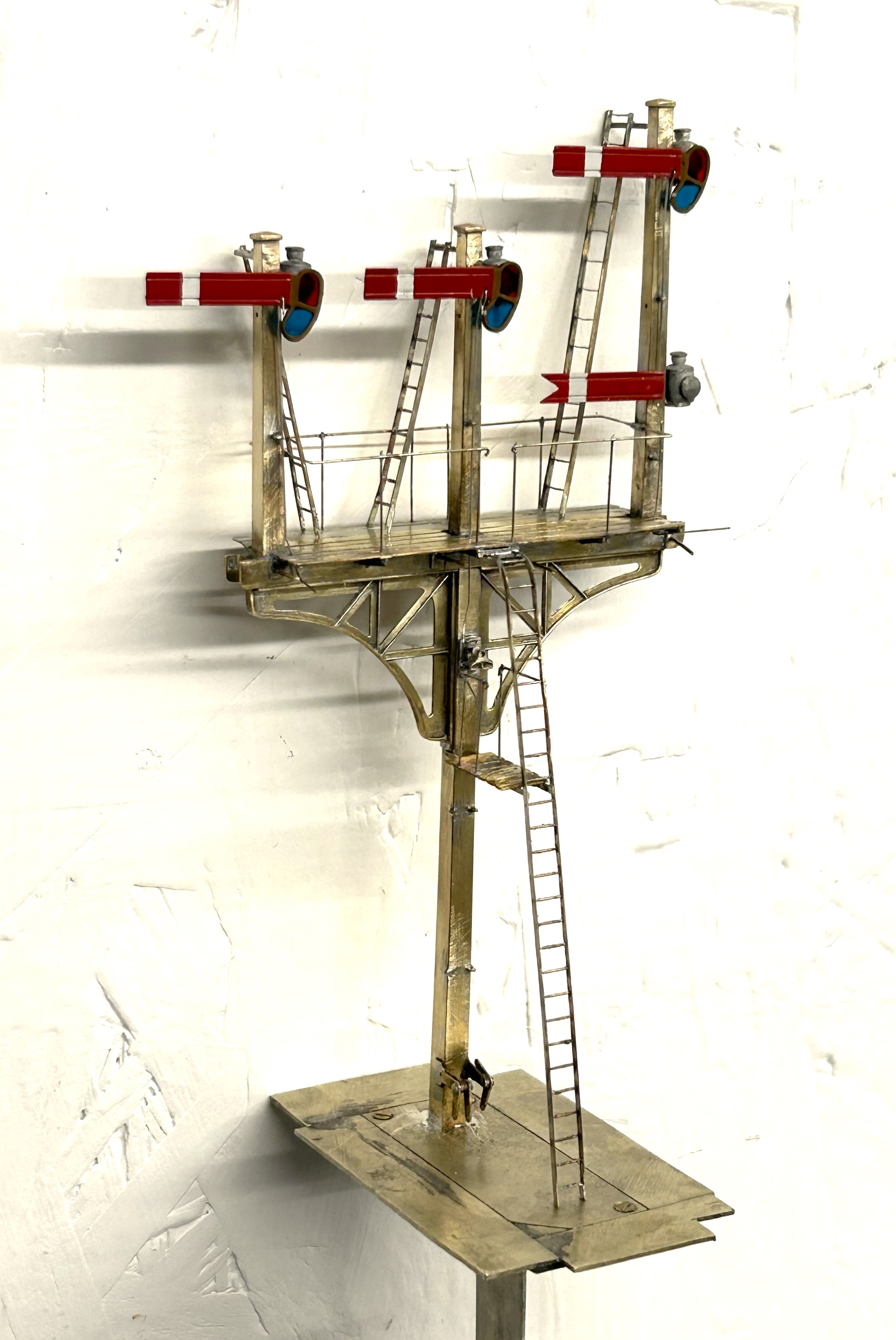
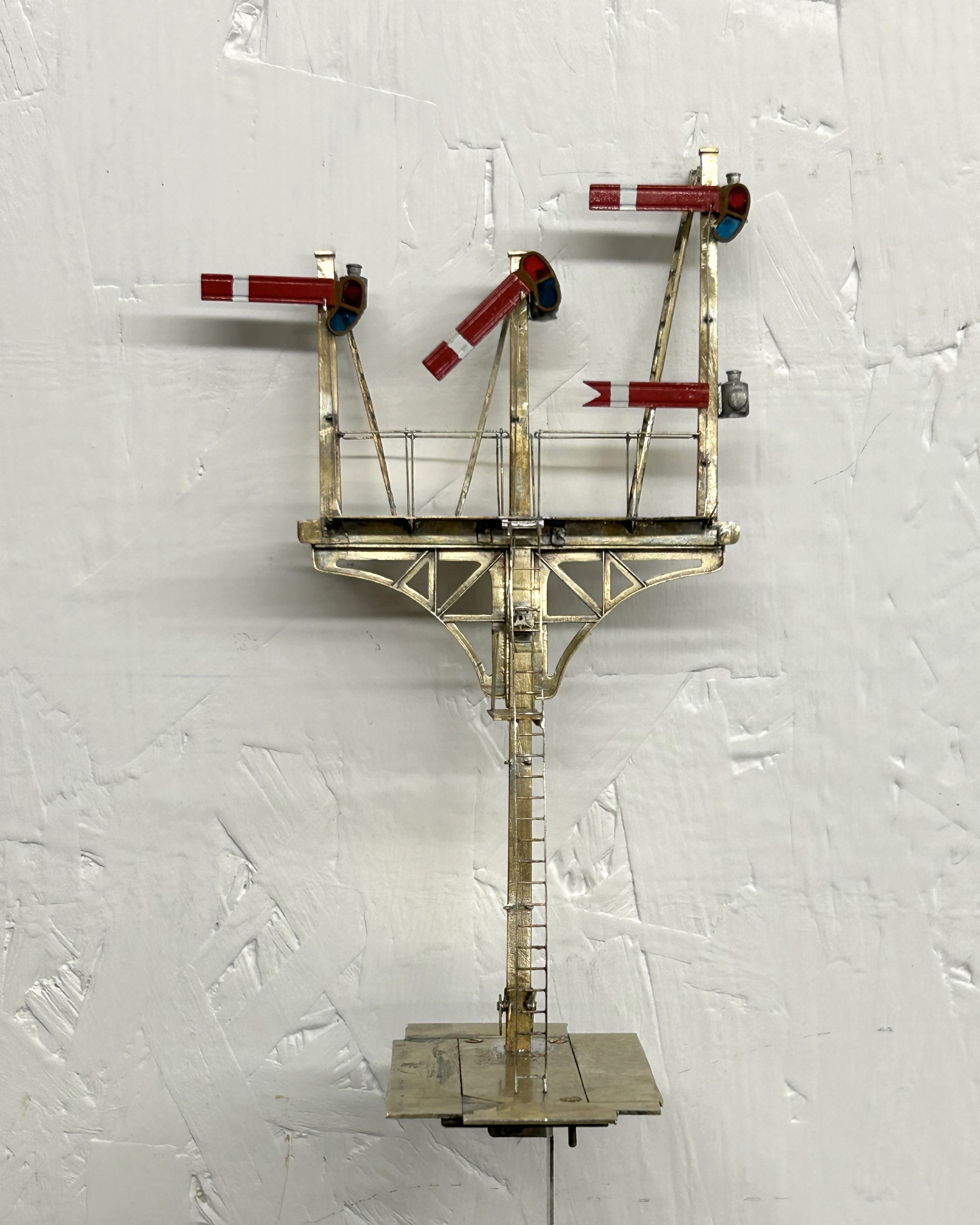
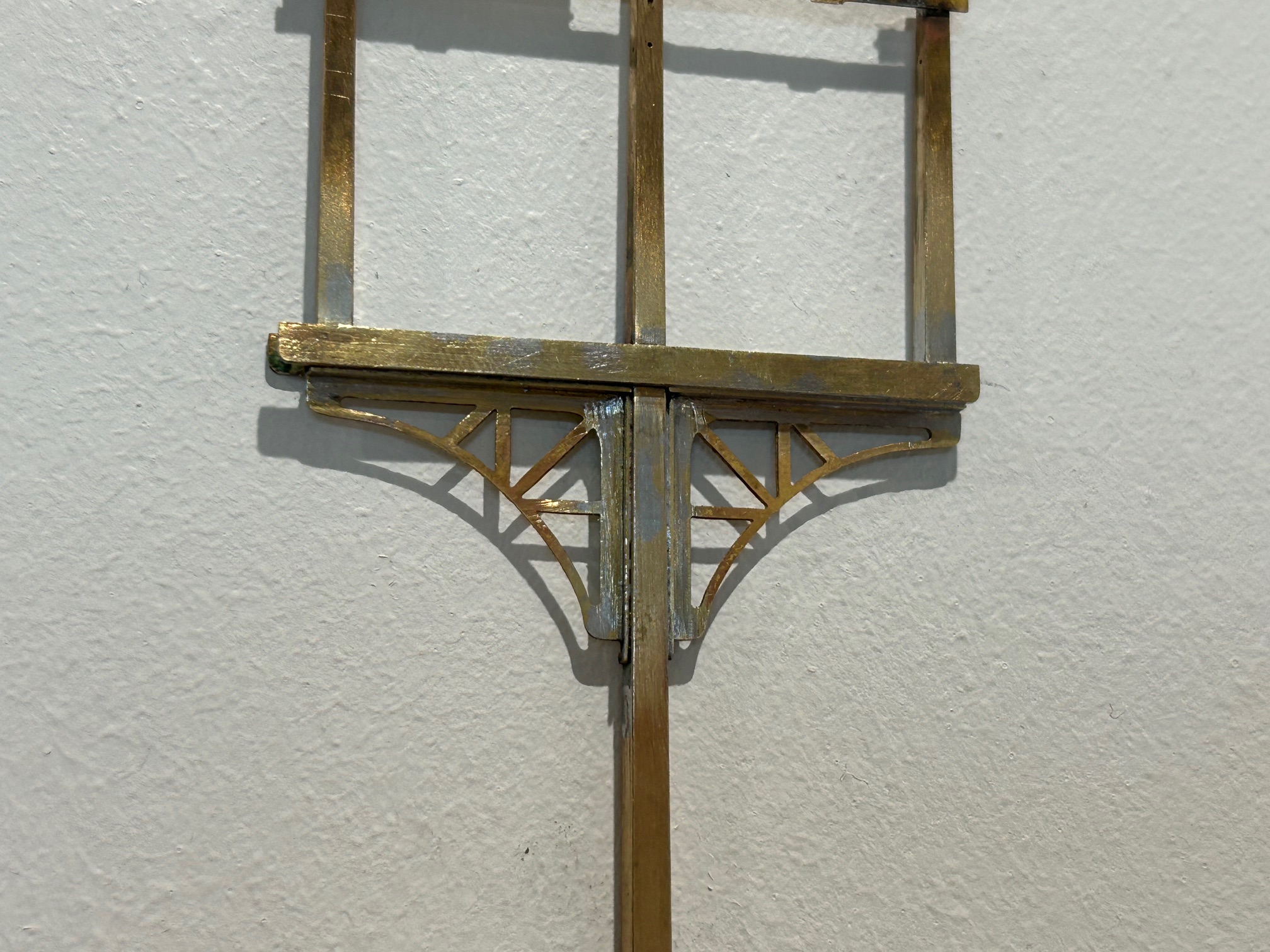
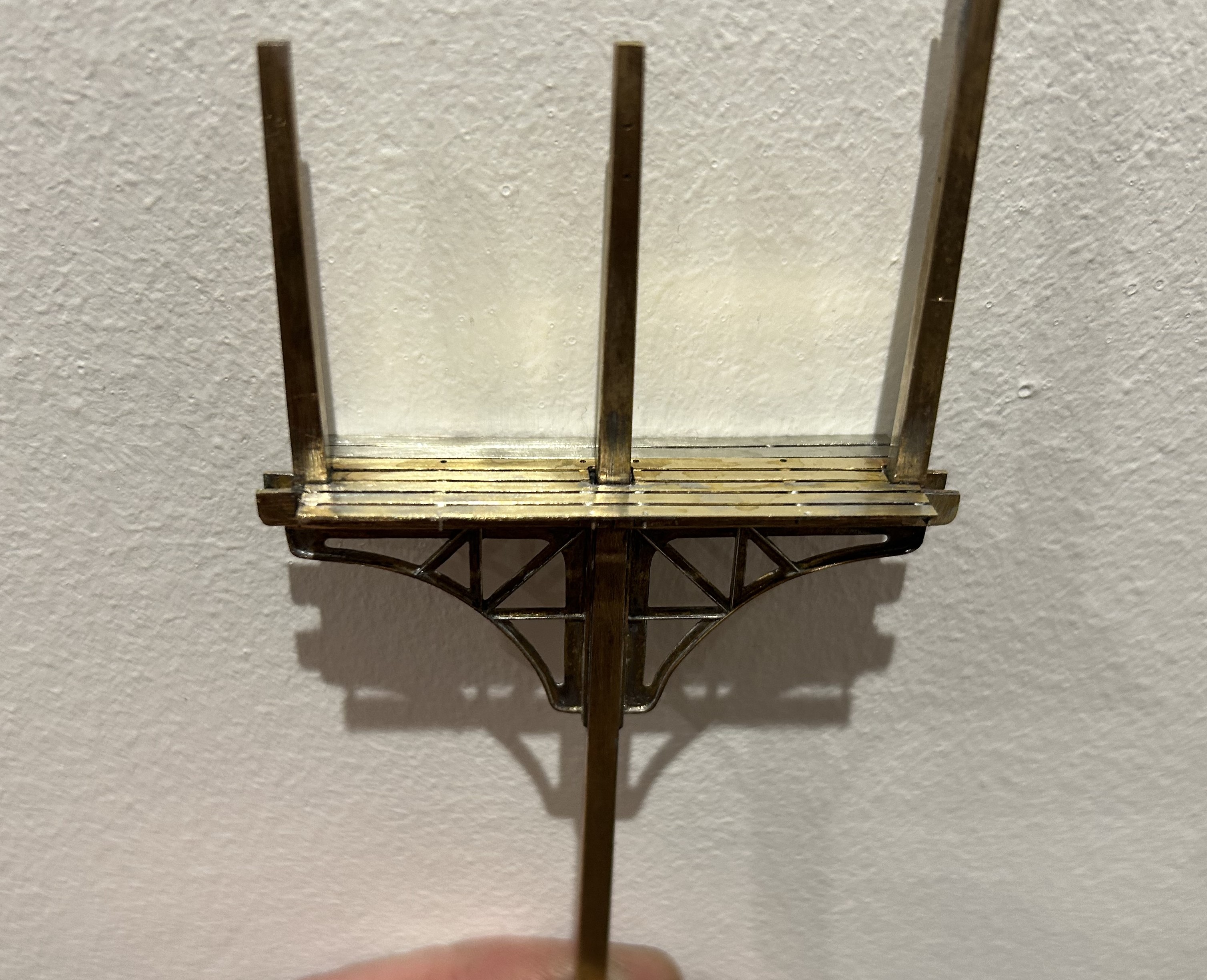
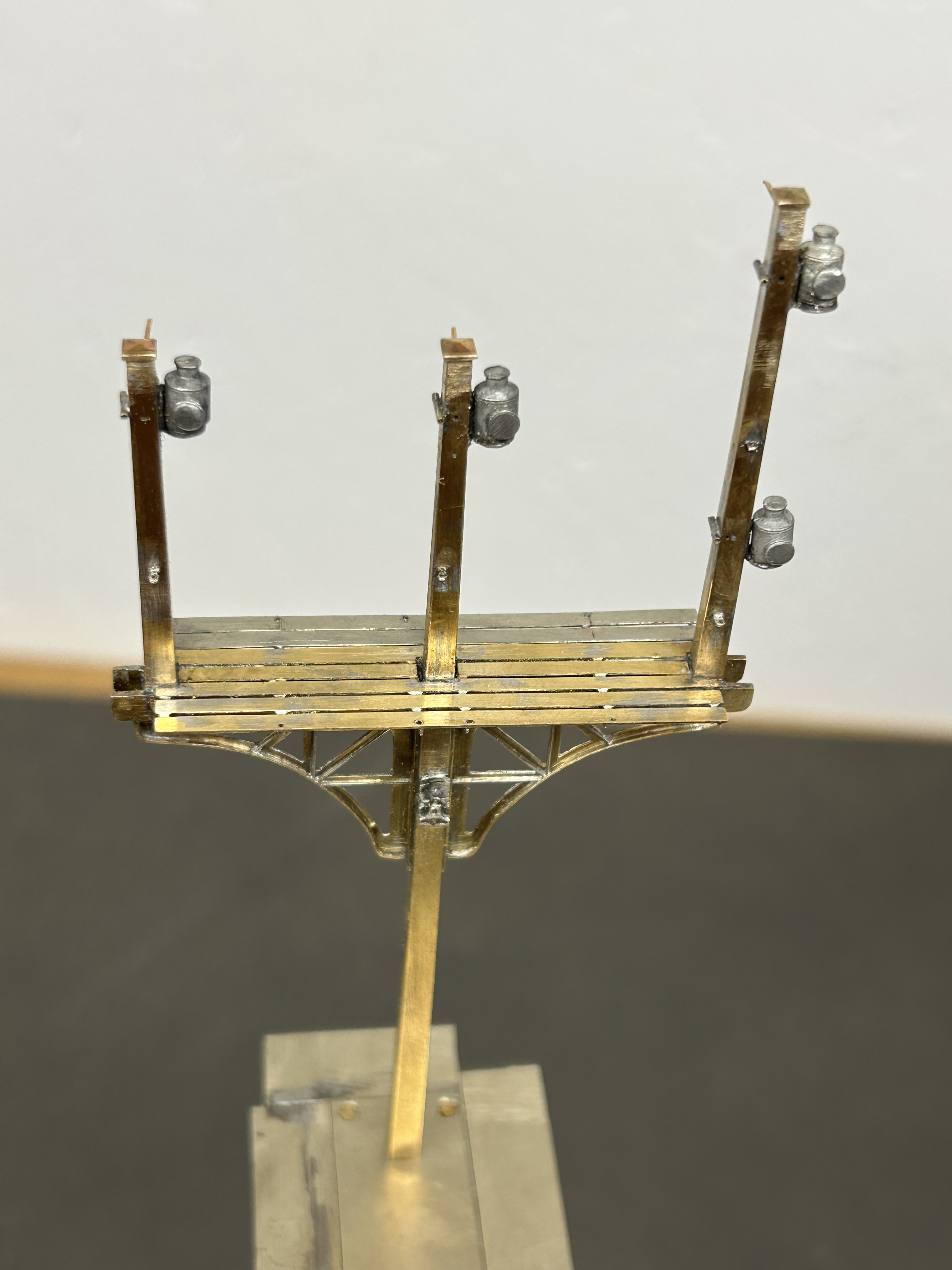
Once the basic structure of the gantry is in place, the real task of making the signals signally commences. First up were the smoke deflectors and the brackets for the balance weights. Also fitted are the main portions of the fan route indicator, but that will be explained further once I get it going!
For the arm bearing point and lamps I am using some 3D prints produced by Steve Hewitt and available from Shapeways. They can be found here https://www.shapeways.com/product/JJRSB … arketplace. They are fairly expensive but they are neat and save a lot of manufacture. There is, however, a but – they are very delicate and I am very fearful of thier long term durability. I am highly likely to draw some of my own up and get them cast in lost wax. It will make them even more expensive but I have about a 50% casualty rate at the moment, so maybe in the long term it will be cheaper!
The arms are Masokits, these are definitely the best available arms for LMS/LNER/BR semaphores. This is especially true of the minature shunt arms as the MSE ones are simply too delicate to bother with (imagine how do I know that………….!). So this is where we are now at with the arms mounted temporarly on the bearings.
There are five movements in the down direction (three of which operate via the route indicator) and then a pair in the up direction – hence the back to front arms.
The plates at the top of the dolls are mounting points for ladders. It transpires they are wrong and have already gone!
So the intensity level has dialled up a notch with these portions (especially breaking the bearing/lamp fittings) but it really gets interesting when you try and make these things work.
I don’t know myself yet (although I know for the couple of arms I have finished, so I have an inkling), but i think it might be fun to have a little sweepstake on how many moving parts there will be in the finished gantry. Five arms, three fan route indicators and each is operated by way of angle cranks. Each arm, crank and intermediate wire counts as a moving part, as do the servos………………..guesses please?

Delayed Delivery – part 1
After a long pause, caused by that irratating thing called life getting in the way, I am looking to deliver on some long made modelling promises over the holiday season.
The major task is a rather full on gantry signal with no less than eight movements on it (which is an improvement, when initially designed it had nine!), including a rather natty fan route indicator. This is for a friend’s layout and is in return for some signal cabins that he built no less than 15 years ago – I told you the promises were long made! Mind you, he hasn’t got the layout fully running yet, so I am still ahead of him!
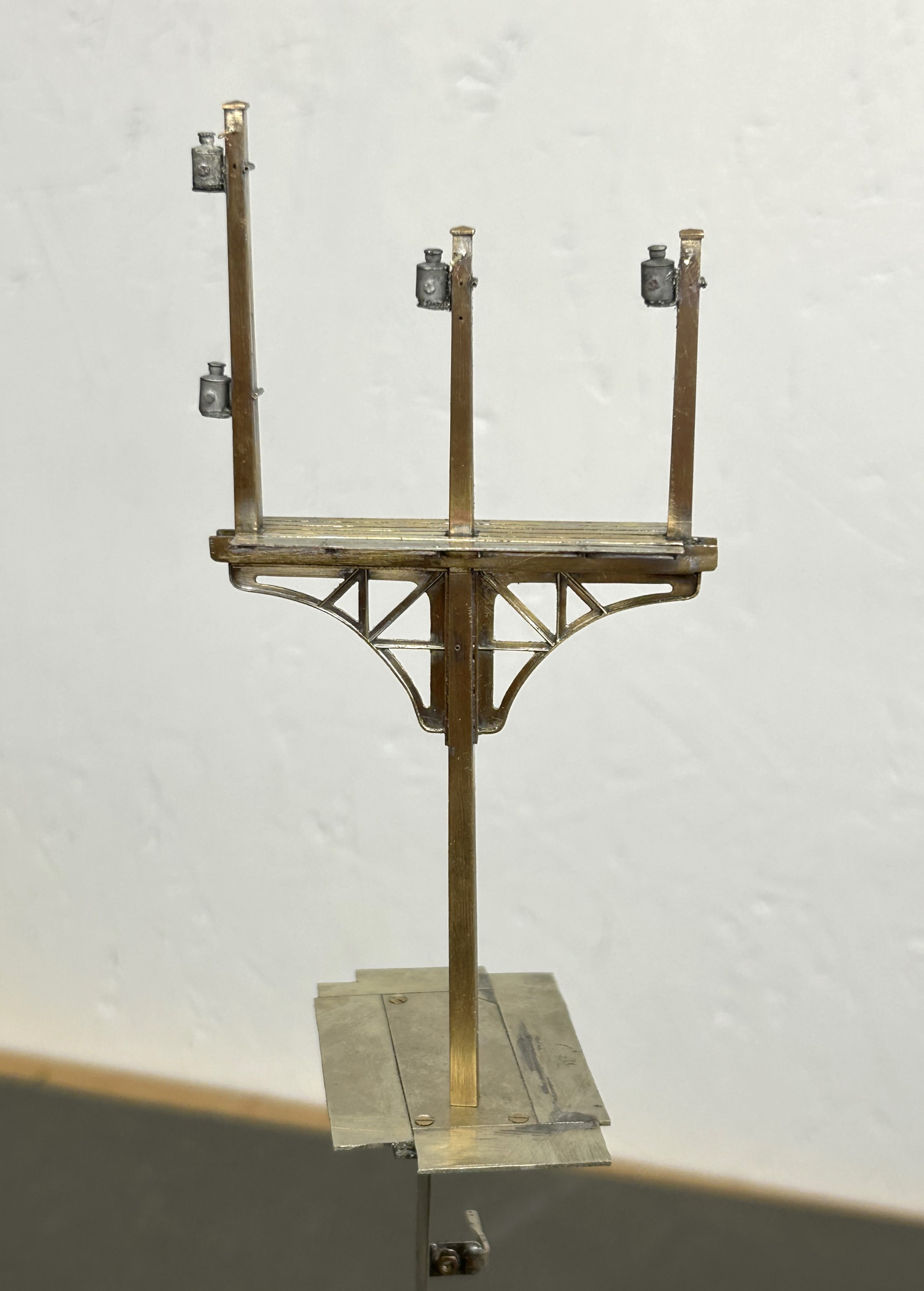
The gantry spans only two lines so it can be formed with channel section. There are good drawings and pictures in LMS Journal no 5 of this. I have made mine from milled brass section and then the landing was a custom etch I designed as it takes a surprisingly large amount of material and effort to construct this from scratch. These etches included the doll base plates although the dolls have a thickened tube at the lower level which of course I forgot and had to undo later work to put on!!
The signal is to be located on an embankment which meant that I could not simply put flat base plates on the foot of the gantry columns. Instead I have constructed a housing that matches the slope of the embankment and then the baseplates are partially sloped to match this with square sections representing the foundations of the prototype columns. Below these baseplates I have then formed housings to take the servos which will eventually operate the arm actions.
So far, this is pretty easy modelling (although I lost a number of drill bits opening up the stanchion positions on the landing – grrrrrr!). The tough bit comes next……………
There are potentially two viewers of this thread who might be thinking that I have long outstanding modelling promises to them too……………I am also working on one of these too!!
Portchullin Goes Green………….Again
Fear not, this is not an announcement that the McRats have been converted from DCC to run on ethanol (although this remains the preferred fuel of the layout’s operators). Instead it is a recognition that after 13 years on the exhibition circuit, Portchullin was getting a little faded and even battered. The colours of the vegetation were fading and the woodwork was showing all the miles they have been lugged about in the back of a van – all in all it was looking like 1970s BR, just not in the right way.
We reached the conclusion that something needed to be done about it and in anticipation of an April exhibition invite, the gang arranged a session on the layout to give it a spring refresh. Sadly the show had become a covid casualty by the time we met up but we convened anyway and even the stone-cold hearted Pete was showing emotion at seeing us all again by insisting on greeting us all with a hug!
So out came the static grass machine, modge podge and various scenic materials and away we went…….
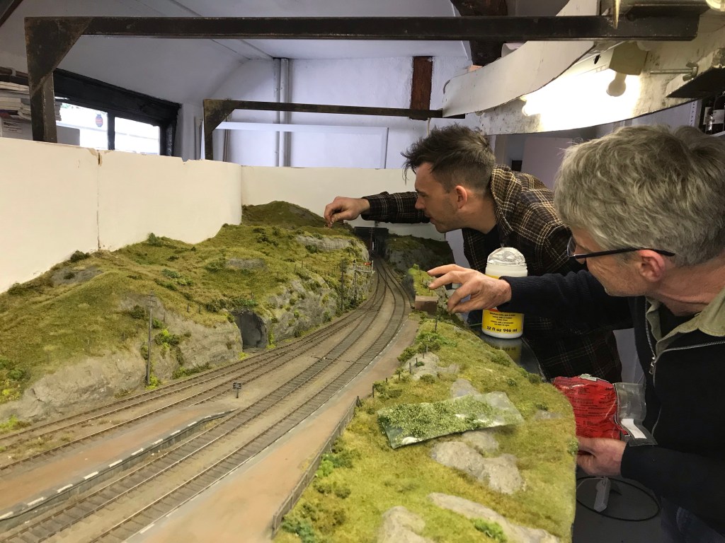
We ended up making quite a lot of difference in only a short while, but adding the dwarf bushes and other vegetation then took a lot of time and I am still thinking it needs more attention.
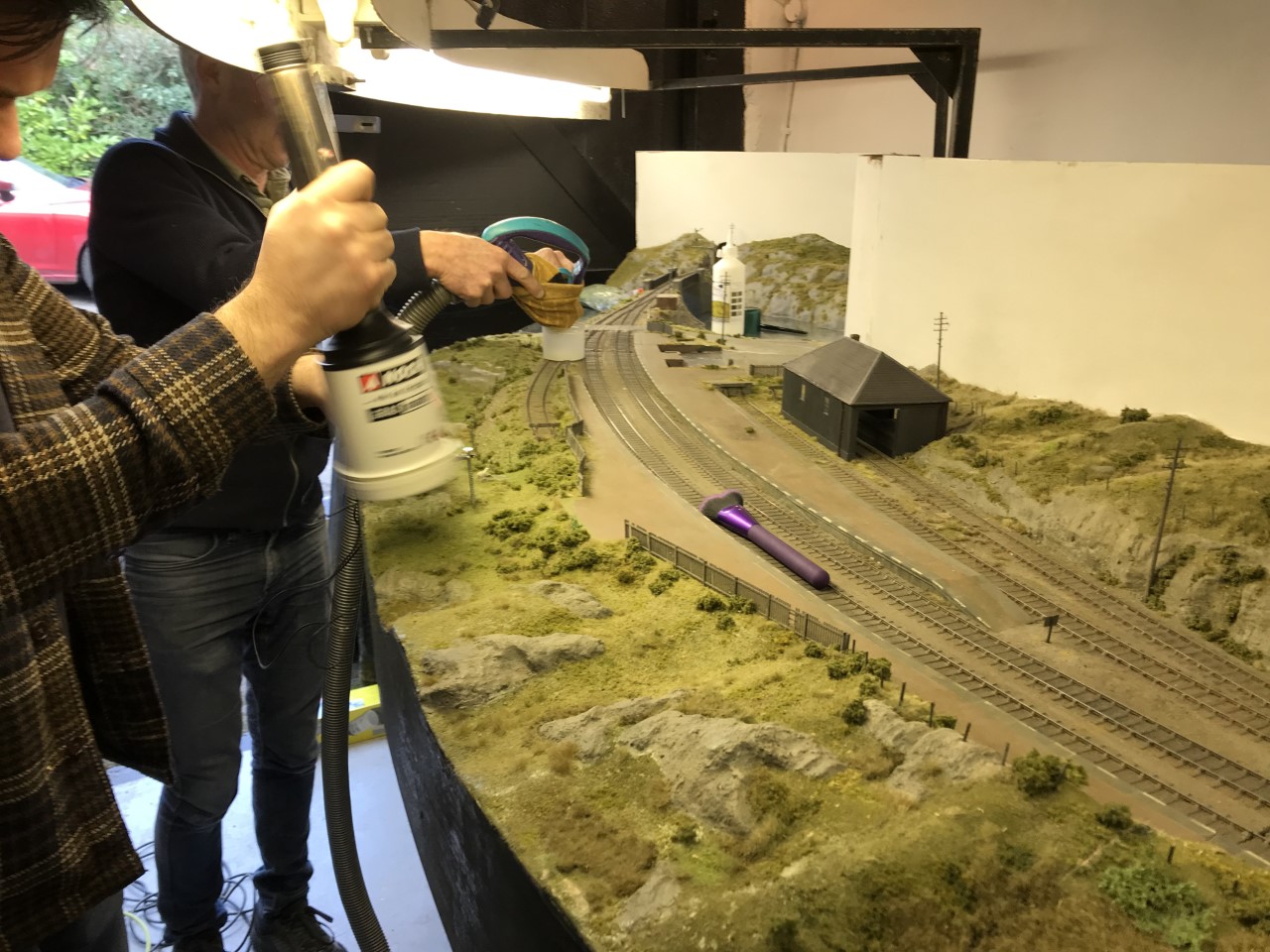
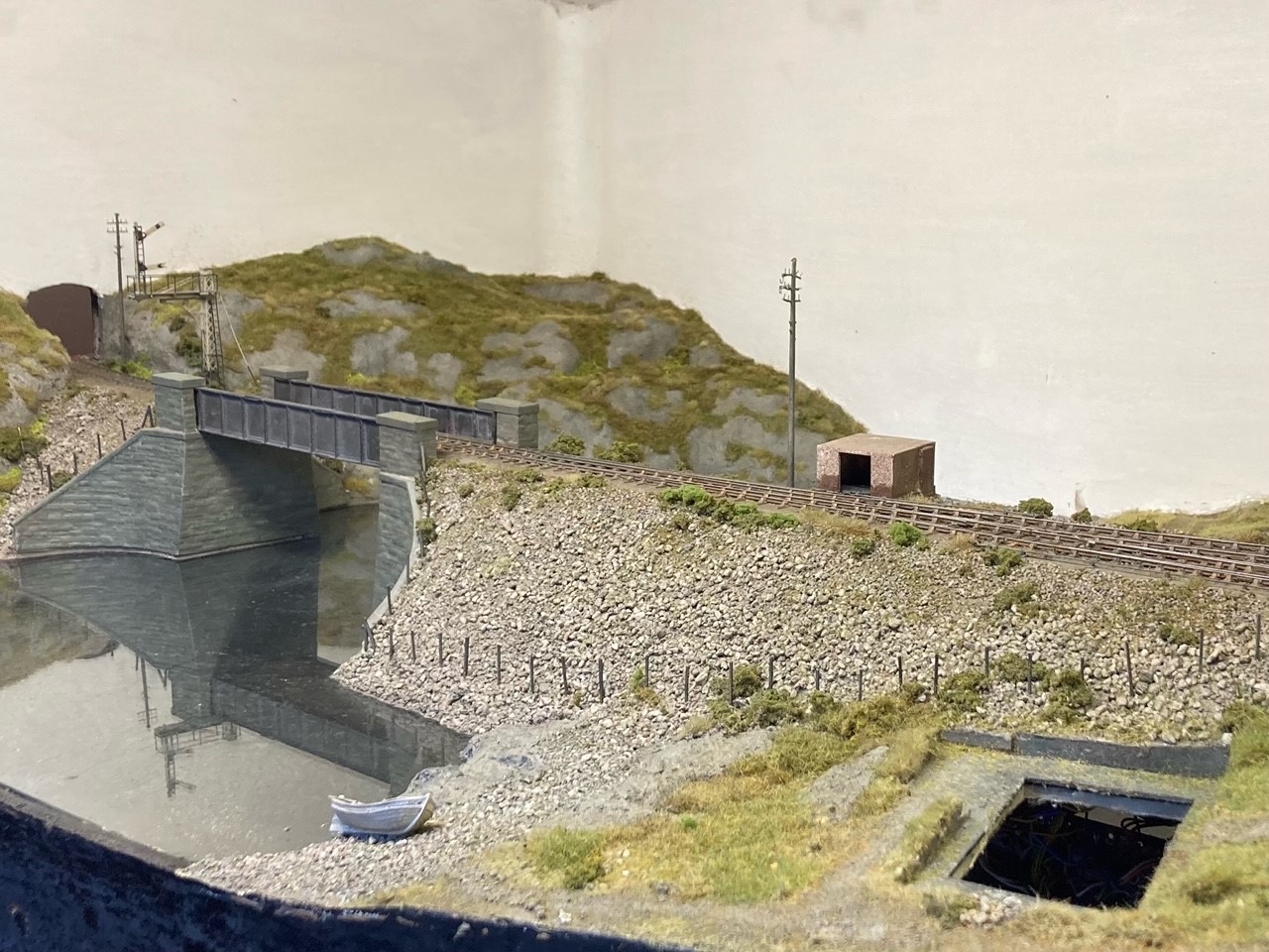
There remains a lot to do, including a revamp of all of the woodshell and lighting gantry, but the layout is looking a lot fresher.
The other main task in hand is a complete rewire. Too often we (well I, the others will have nothing to do with my wiring) have had heads under the baseboard trying to sort out either point-motors or errant wiring, it has to change!
Normal Modelling Will Resume Soon…..
Sorry for the absence of any posts for rather a long time………..
We decided to move house, for a few reasons (a pleasant side effect of which is I can build myself a larger railway room) and this has been nearly all consuming for a few months. We are now moved and whilst we remain surrounded by boxes, normality is slowly returning to our life.
So some modelling posts soon, but first a summer holiday!

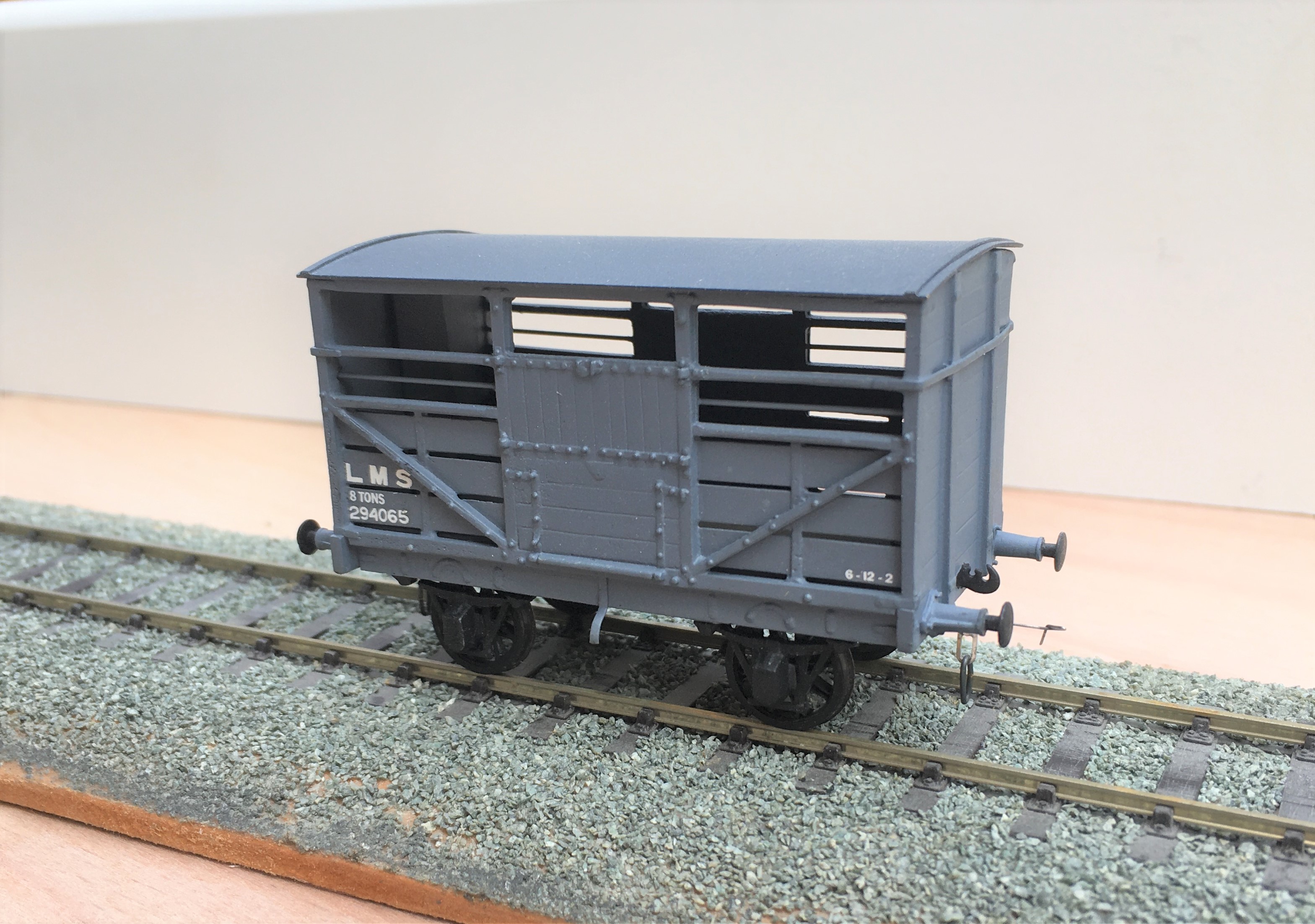
A Fold of Cattle Wagons
Your pub quiz fact for the day is that the collective name for Highland cattle is not a herd, as it would be for most cattle. Instead, and only for Highland cattle, the collective name for a group of cattle is a fold. If that does come up in a pub quiz, you owe me a pint!
Cattle were an important part of the highland economy and hence were a good source of income of the Highland Railway. In my slightly distorted version of real history, there were 4 million head of cattle to transport per annum in the Glenmutchkin area (which is remarkable given the cattle population of the entire UK at the time was only a little bit higher!). Thus, a fold of cattle wagons was obviously a pre-requisite for Glenmutchkin and this is what I have been working on of late.
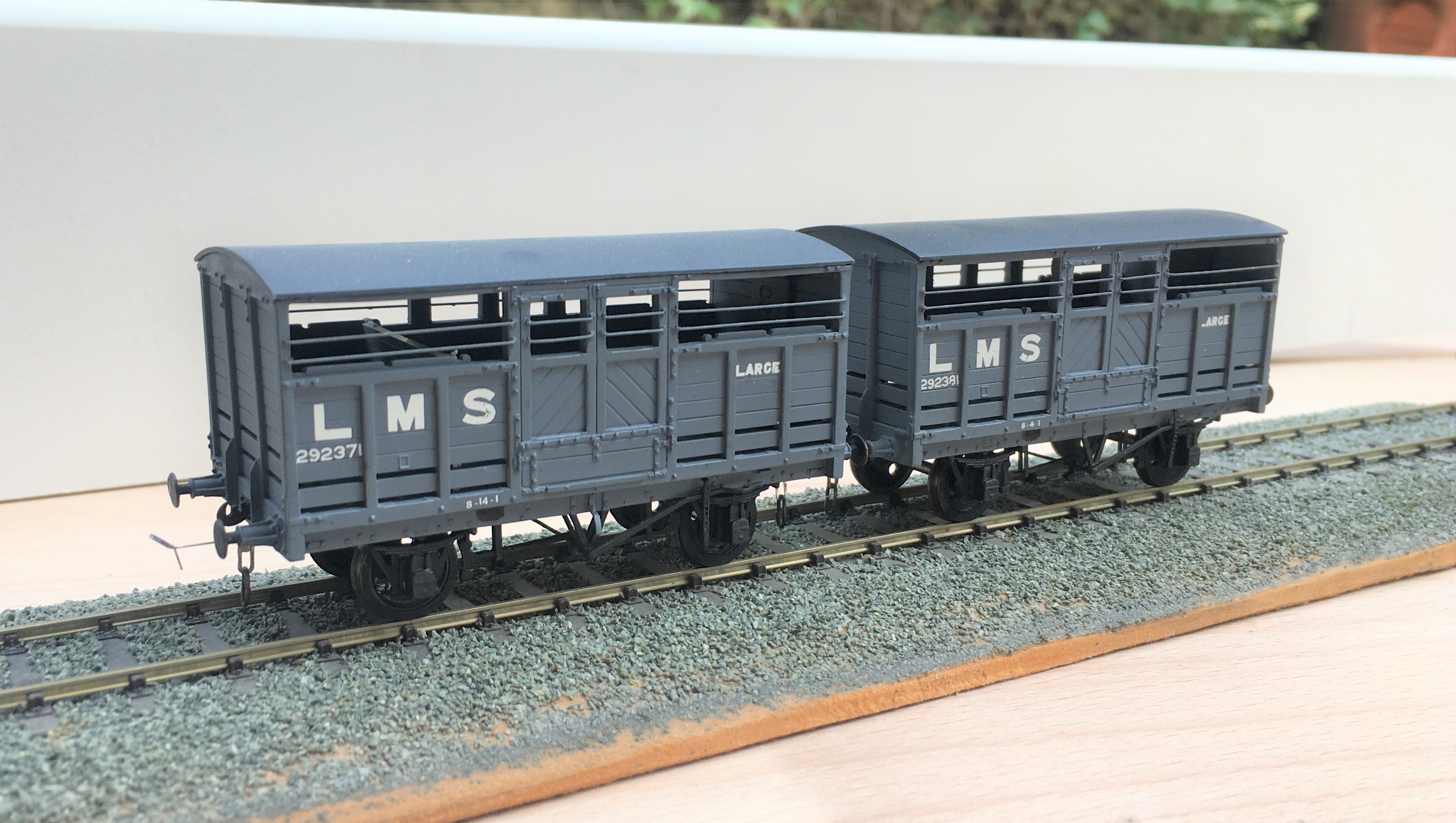
First up are a pair of LMS standard cattle wagons; to diagram 1661. These date from 1925; so they would have been fairly new at the time that my layout is set in. These were built from Parkside plastic kits with only moderate modifications around the break gear and, of course, some sprung w-irons. Being a relatively recent kit, it is generally very good and whilst it is possible to convert it to some alternative variants, these came later than my modelling period so I was not tempted. I am concerned that I have painted them rather to dark though, so I will be weathering them on the light side.
Next up is a Great North of Scotland Cattle wagon, from a Model Wagon Company white metal kit. This is a much older kit and didn’t it felt it! For reasons I am not certain of, the two sides were not the same length so in practise the body is a bit trapezoidal – but can you tell? The casting was also covered in flash which was a particular problem in the gaps between the wooden slats – this meant I spent a few hours I would sooner not have spent scraping it out to keep these clear. The GNoS vehicle was a much more basic vehicle and, strangely, did not get any large ownership lettering so they remained rather anonymous, Instead, they had simple cast plates, which I made from a locomotive number plate and dry brushed white on the letters. I have glossed over the fact it does not have the right number or even a consistent number from one side to the other – sod the “getting it all right” mantra!
I have also built a further Highland cattle wagon, built from a Model Wagon Company kit. This is the Drummond era version and I have already built a number of these so this was relatively routine – its just as well as there are still a couple in their packet waiting their turn!
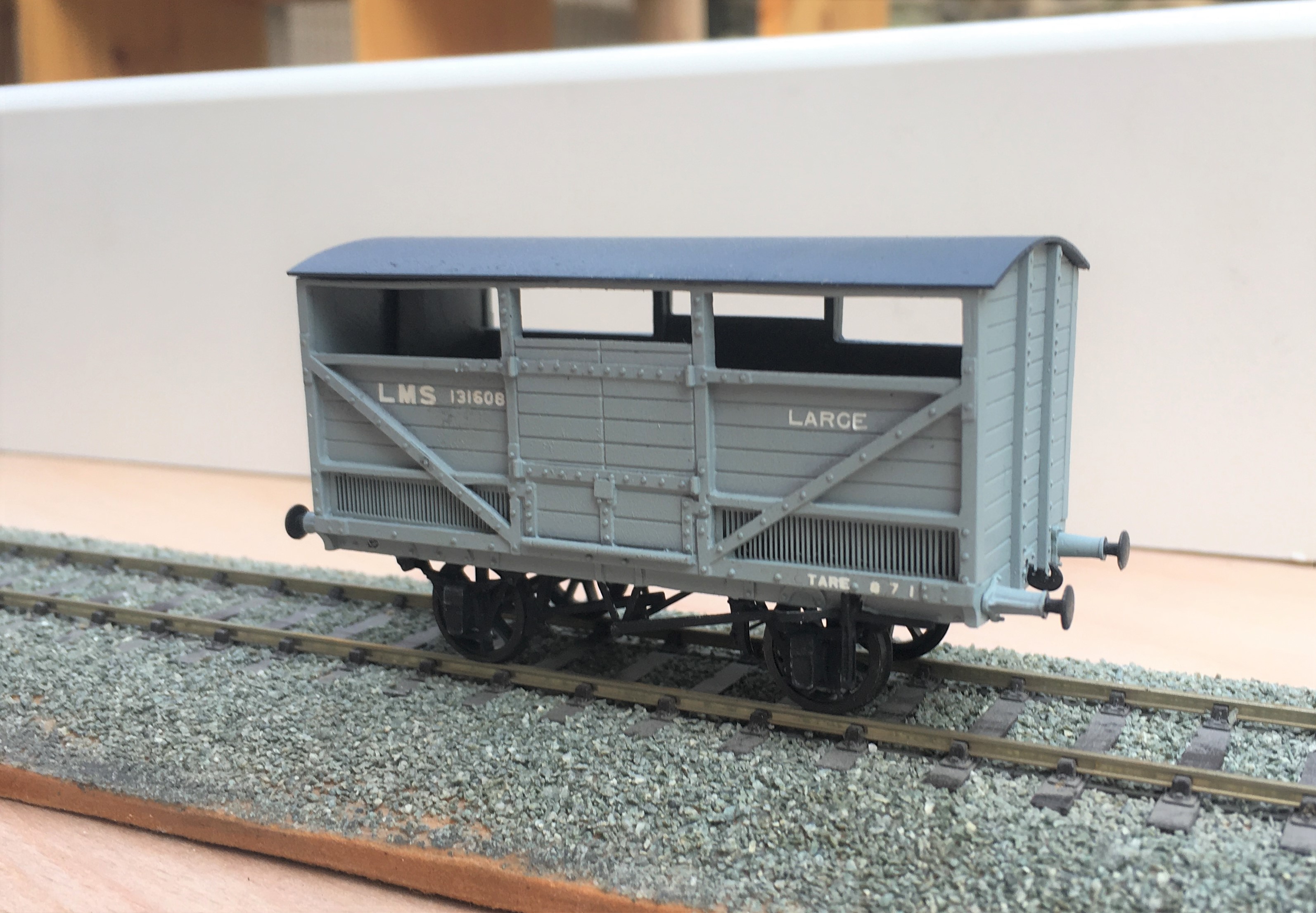
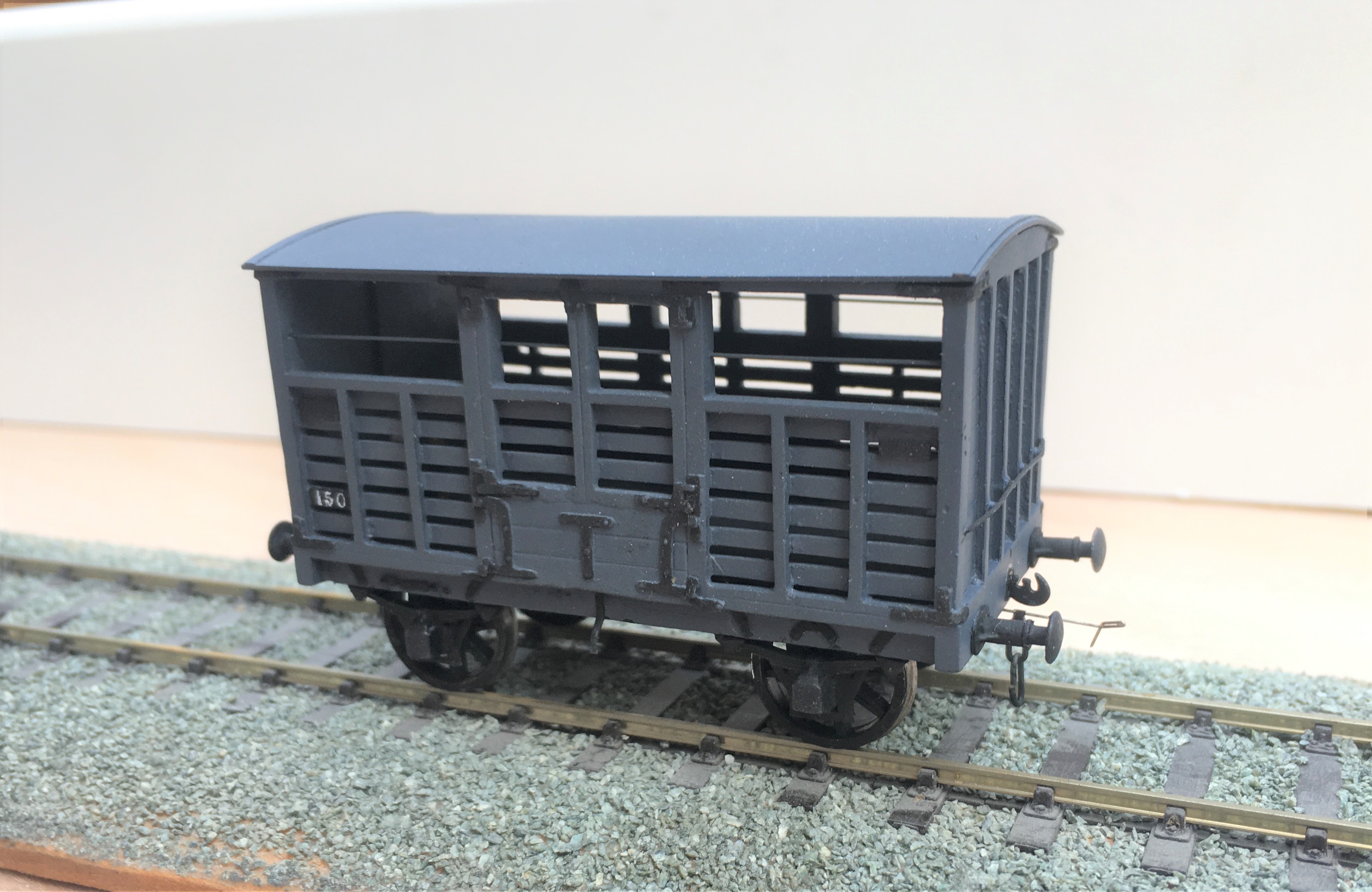
The final cattle van is a David Geen kit for the L&Y large cattle wagon. Whilst still a whitemetal kit, it is of somewhat better quality than both the Model Wagon Co kits so was rather easier to make. Even then, it did need filling at the corner joints and I felt the need to swap the brake levers for replacements – why to even the better manufacturers use the same material for all of their kits?
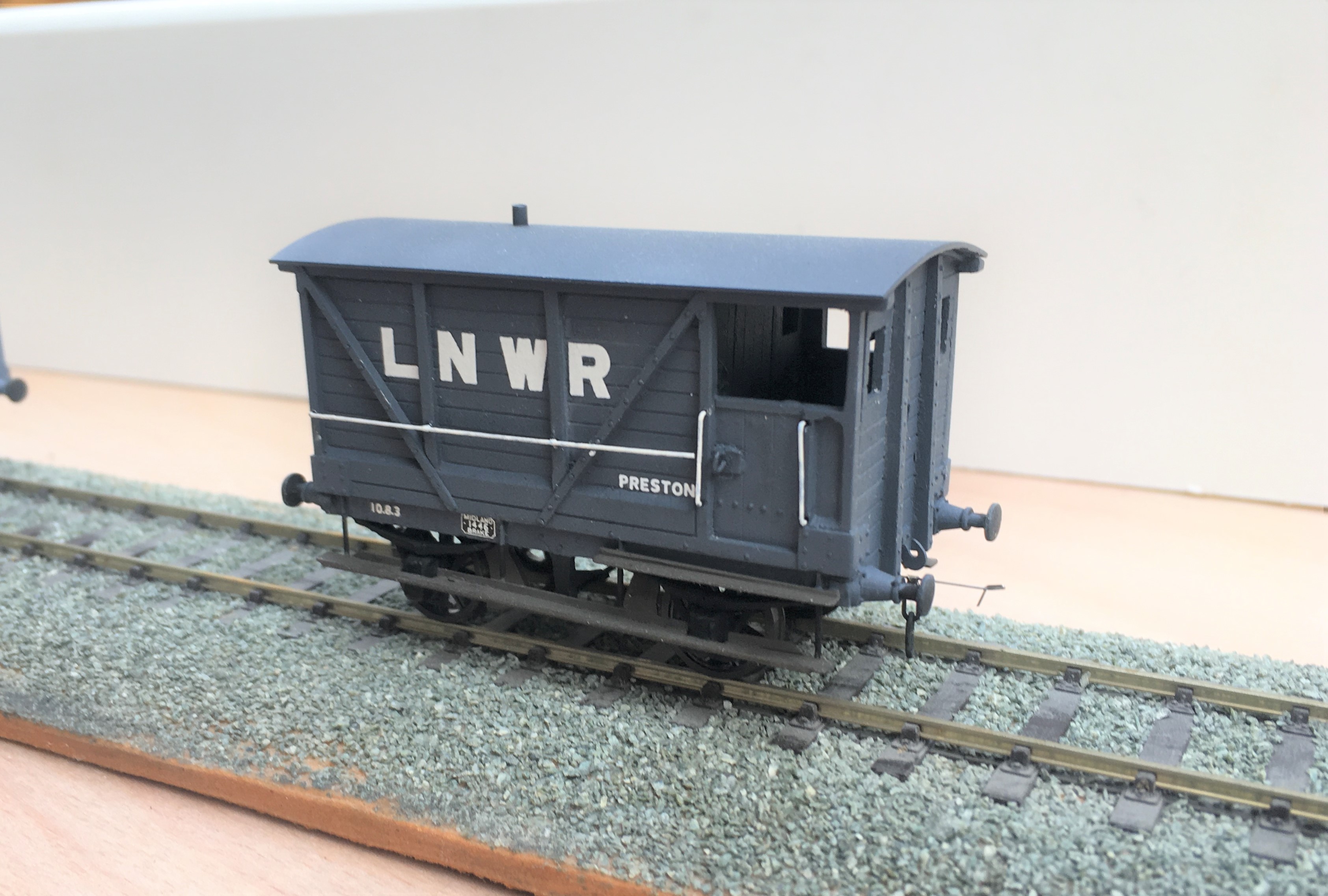
To finish of this little rake, I obviously need another brake van. This is not so obvious because this is brake van no 11 in the collection and I know I have at least one more spirited away! Whilst this was a kit build, it was first a kit unassemble as this was a vehicle I had first built in my teens. Generally fairly well but a couple of bits had got damaged over the years so I felt it needed rejuvenating.
And here they all are on parade.
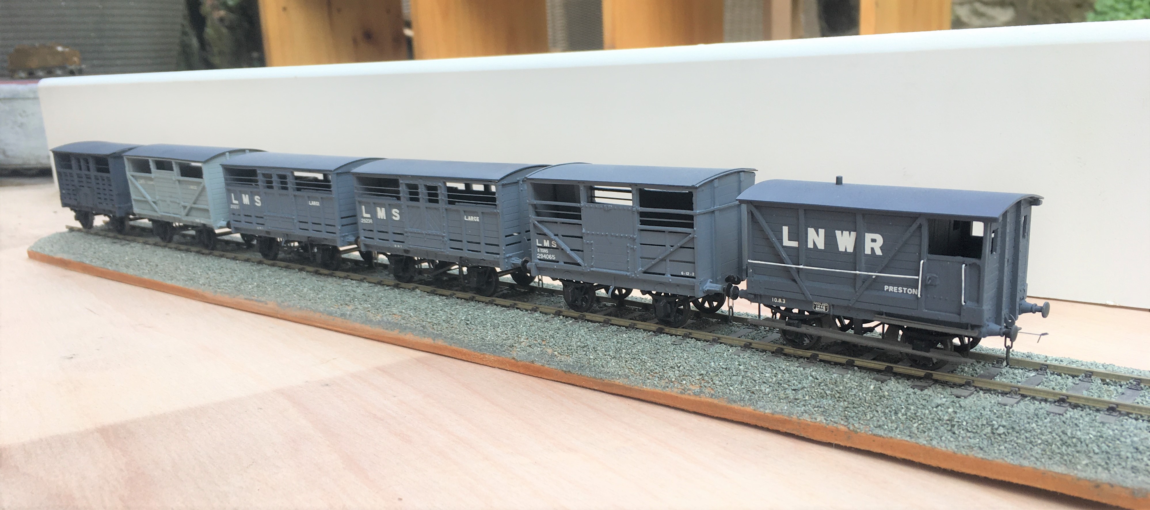
Now all I need is rather a lot of heilen coos to fill them up with. I have been working on this but it seems that resin casting is a tad more difficult than I thought……………..
Oh and yes, they are all way to clean; another weathering sess’ is required guys………..

Euston Departure
Being fundamentally an LMS man, I have recently joined the LMS Society. The cover photograph of the first Society newsletter that greeted me was so fabulous I thought it was worth sharing.
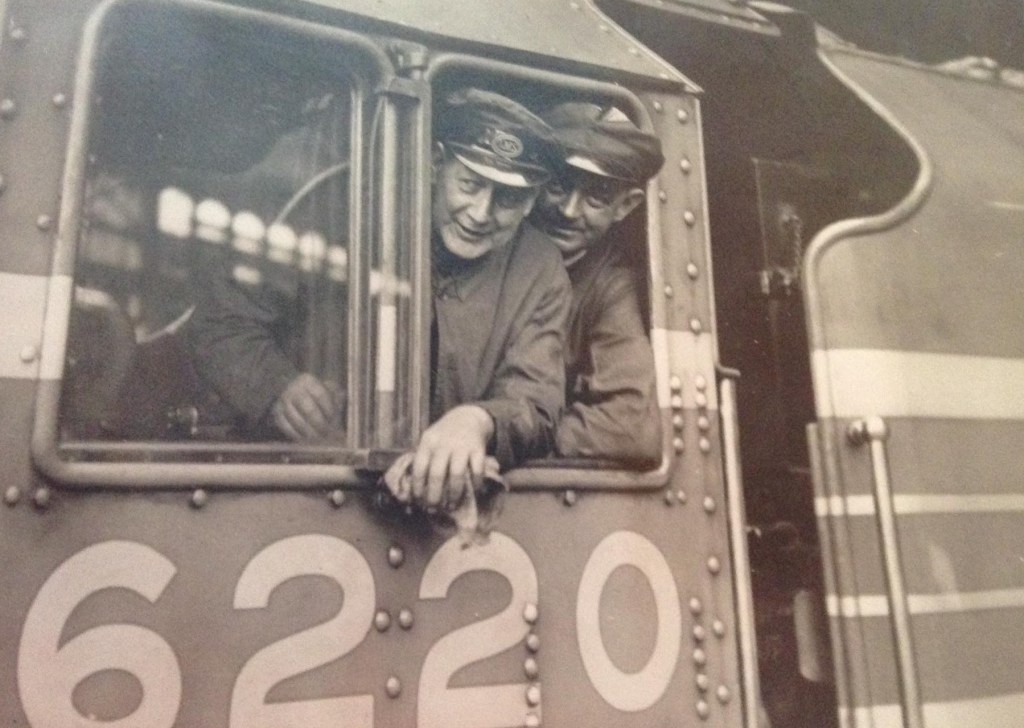
This is 6220 Coronation awaiting the right of way from Euston, sometime between June 1937 and the outbreak of the war. Driver Fred Bishop is peering out of the cab roof ventilator in what must be an official photograph posed shot for publicity purposes.
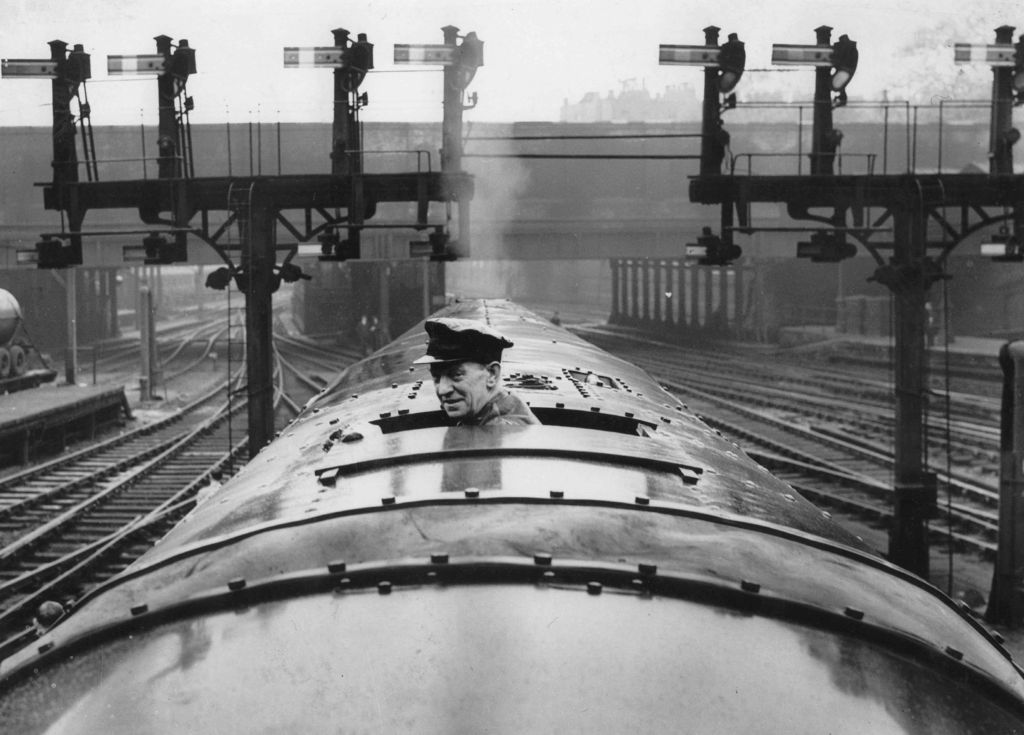
Coronation was the first of the Coronation / Duchess class introduced to pull the LMS’s premier train, named the Coronation Scot, and inaugurated on 29 June 1937. This was launched in competition with the LNER’s comparable train which was launched a week later and called the Coronation. Both trains were named in honour of the coronation King George VI.
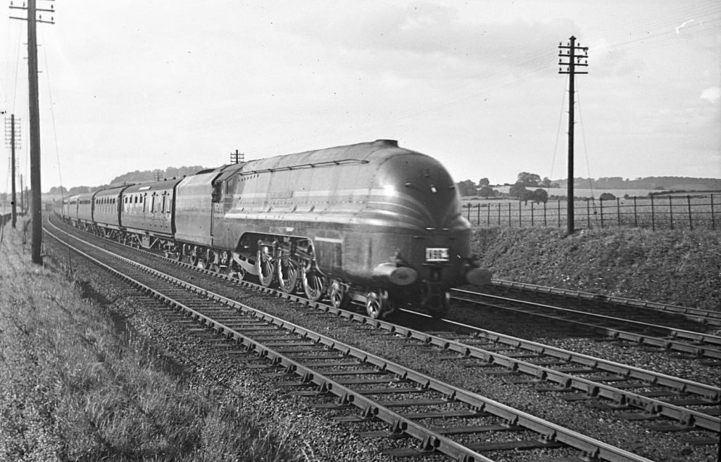
On its inaugural press run Coronation became the world speed record holder with a speed of 114 miles per hour on Madeley Bank south of Crewe. Unfortunately the jubilation of taking this record became consternation as the footplate team realised the train was still making 110 mph only a mile and a half from Crewe. Urgent braking brought the speed down but the locomotive still passed through the station’s reverse curves at 57 mph, well in excess of the 20 mph limit. The resultant bouncing alarmed the passengers and destroyed a quantity of crockery in the dining coach! It discouraged more record breaking attempts for a while, although famously the LNER’s Mallard retook the accolade in July 1938 with a record that still stands today.
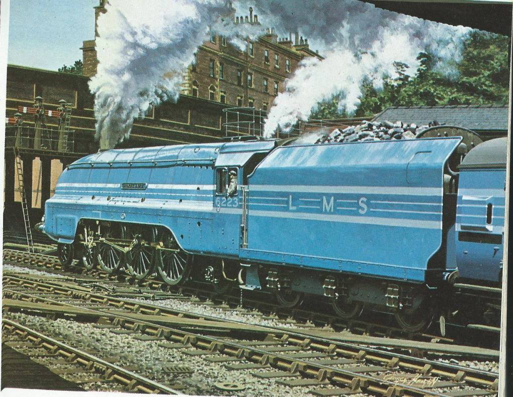
Whilst I am not against the A4’s, surely the blue Coronations with their stripes and a matching train behind had the ultimate wow factor of the pre-war railways?
What tends to get forgotten these days is that in the 1930s the top link drivers on the crack trains were major celebrities of their day. Had Ant & Dec existed back then, you would have found some of them in the jungle alongside annoying footballers and has been musicians! Fred Bishop was one such driver and his auto-biography (Queen Mary of the Iron Road – Jarrods, 1946) was a well known book of his time. It seems a long way from the grime of the inside of a locomotive cab being worked hard!
Only the first batch of Coronations were painted in blue; the second set of streamliners were in Crimson Lake with gold lining and were aimed at hauling prestigious but not bespoke trains. This (I think) is King George V and is in this livery.
Whilst they may have only really existed in this form for three years (as once war was declared, many were painted black and they were de-streamlined after the war), the LMS streamliners do hold quite a soft spot in my heart!
Hornby already produce a very good model of the locomotive and are shortly to produce a number of the matching coaches; maybe I will be able to resist, maybe I won’t!
photographs with thanks to Ian Beattie and Jim Smellie
