Blog Archives

Calming an Exhibition Manager’s Nerves…………
So with nine weeks to go (a couple of which will be lost with a summer holiday) to Glenmutchkin’s first outing at Scaleforum, the state of progress is at the forefront my mind! It is probably rather more at the forefront of the exhibition manager’s mind!
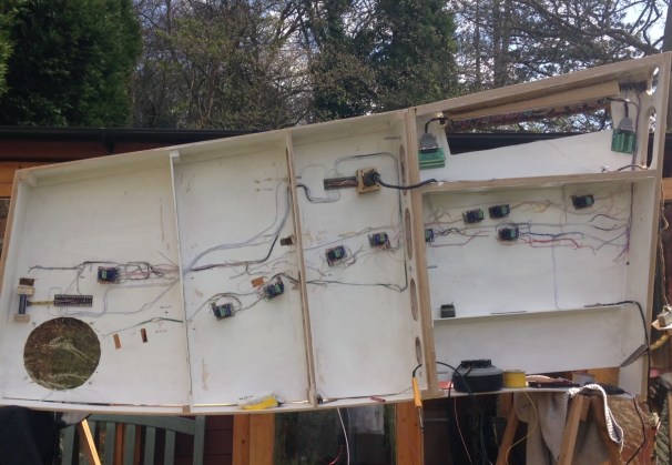
So help to calm the Scaleforum’s exhibition manager’s nerves, here is a progress report and update photographs to prove that even if I have not been providing many posts, progress is being made on a number of fronts:
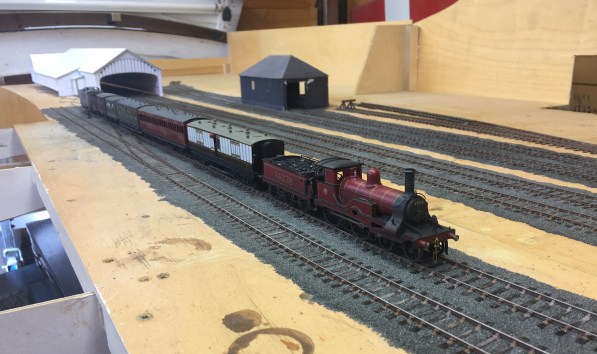
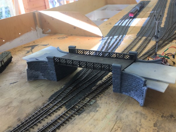
Most of the track is laid and wired; much of it is also ballasted, although it still needs colouring.
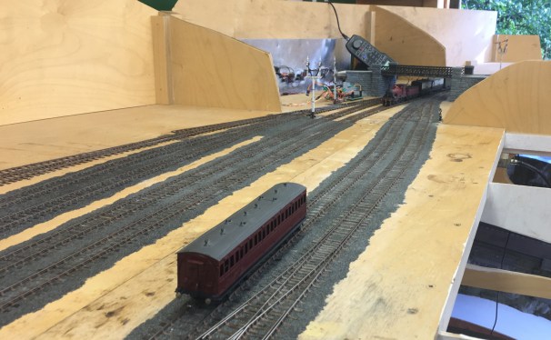
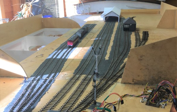
Most of the signals are finished but not yet linked up (which explains some of the droopy angles of the arms!). There will be more posts on this topic soon.
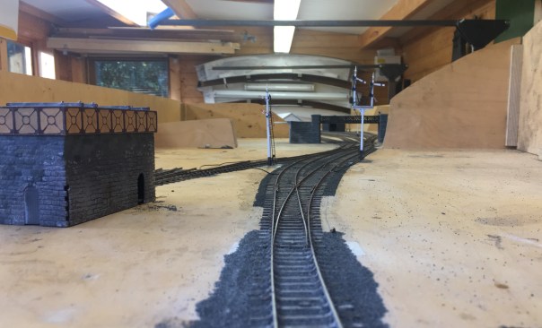
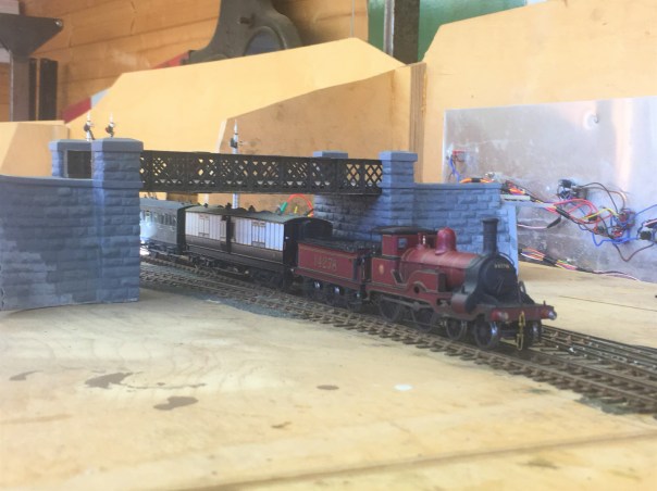
The principal bridge has been finished for a while, but it is looking a bit more “at home”.
…..especially with a fine loco to set it off.

The Glenmutchkin Pharmacy – Part 1 The Etchings
It is a fair time since I built my last building, so feeling that it was time that I rediscovered my mojo for architectural things I have made a crack at a building that will be a fairly key feature on Glenmutchkin – its pharmacy .
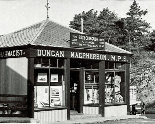
This is inspired, and largely a facsimile of, The Kyle Pharmacy that could be found on the approach to the ferry pier. Or at least it could until the 1970s when it was swept away to make a larger car holding pool for the ferry. In addition to being a characterful building, as you can see below, the real pharmacy at Kyle was a key part of the local community and I wanted to capture this feature in Glenmutchkin.
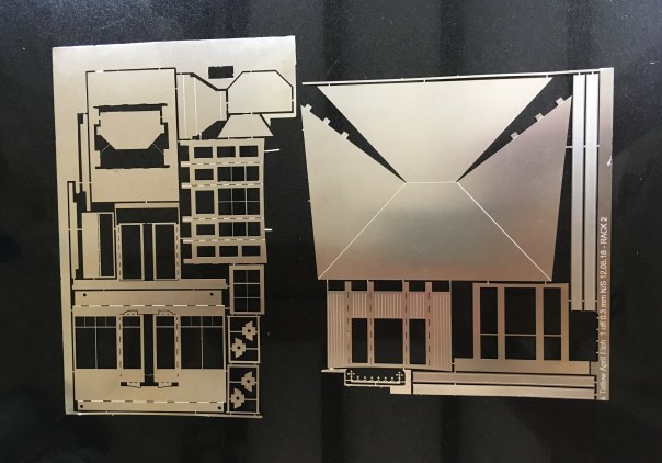
The pharmacy building is going to be located on the most prominent position at the front of the layout, so it definitely deserved some time being spent on it. Taking Peter Bond’s advice, it is going to be assembled in components which will make painting a great deal easier but rather than using plasticard throughout as he would have done, I have arranged to have the shop front and bay etched. I did so as I concluded that getting the slenderness and crispness of these was going to be key to get the feel of the model convincing. Peter is a professional architectural modeller and bending plasticard to his will is therefore his stock in trade – not quite so me!
So these are the basic etches back from PPD:
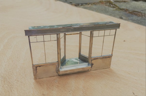
Some of the bay assemblies and the bay largely completed:
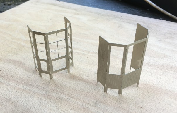
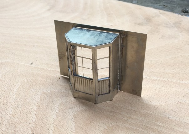
The real value of etching the components can be seen in the shopfront – I at least can’t get plasticard to look like this!

Two Steps Forward and One Back
Having taken a few days off to make a long Easter break and absent the family for a few days, I have set about the wiring of the layout as it has laid untouched for too long!
First things first was to mount the control panel and rather smart it looks too……….
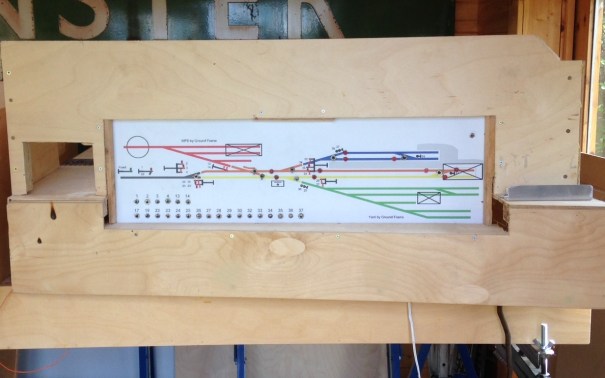
Control panel mounted in situ; a gap for the controller to the left and the aluminium strip to the right masks the power district switches.
Then onto the wiring itself, which takes a surprisingly long time…………….this is only about 50% finished!
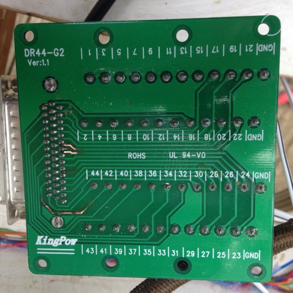
The two key boards to the station throat
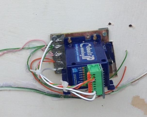
One of my slightly better ideas (you’re about to find out about a less good ones!) has been to make up mounting pieces for the DCC Concepts Cobalt point motors. These are inspired by those designed for the Tortoise units and work on the same principal; they have a uniform mounting arrangement so once set up the actual point motor can be swapped over if need be without disturbing the set up. This is what they look like:
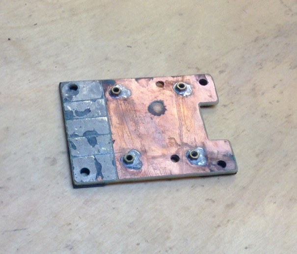
Cobalt Point Motor Mount
Nothing too revolutional, but I hope it will make changing these at exhibitions a lot easier as this is the absolute devil on Portchullin.
And the less clever idea? Remember the multigang sockets I had used on the control panels (link here) well they are not rated at a sufficient capacity to operate the point motors. I think this is because Cobalts operate on a stall basis (the motor doesn’t turn off, it just stalls when it reaches the resistance of the physical stop). My guess is that this results in quite high ampage draw and has led to the following:
The multi-gang sockets with burnt out sections to the left.
Ooops! Back to the drawing board (or rather traditional tag strip) for the linkage of the control panel to the board.
There have been other problems too; the carefully recorded wiring lists proved to be wrong on occassions so I have had to prove each cable run (dooh!) and I found one of the power district switches was defective (but only after a couple of hours of trying to trace the fault!)
So things are getting there, but we are still not at the stage of the first wheel moving!
