Blog Archives
Slips, Moans and the Third Way
A while back I outlined the struggle (that may have been largely in my head!) with wiring the single slip into the MPD. After some frantic reappraisal of this as the layout was being set up at Scaleforum (thanks Chris!), it was fully operational.
Given this is a further blog post on this slip, you can tell there is a but……….. In this case it was that route setting the turnout such that it was electrically correct was not intuitive. The difficulty lay in the straight through route – to set it electrically for the route through on the main required a different arrangement of the switches to that for the straight run from the loop to the MPD. This was even though the physical route setting could be exactly the same, so it become quite confusing! Not having a power district breaker meant that the layout locked down rather too frequently as a result.
Although I don’t see it myself, the guys think that one of my main operating crew has a bit of a reputation for being a moaner when things aren’t as easy as they could be…… With this in mind, it is clear that I have to do something about this to keep the peace. In addition to the use of LED route identification lights on the control panel, I have found a third way of powering the crossings on the slip. Its this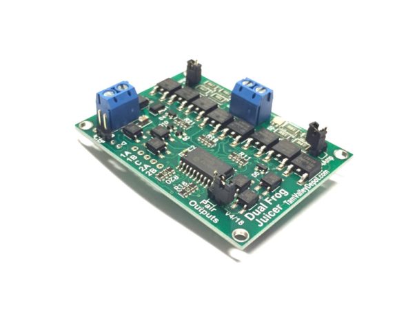
This is a frog juicer (apologies for the Americanism!) and is simply a device that detects a short-circuit when a vehicle hits the crossing. Instead of tripping out (as a power district breaker would), it swaps the polarity. This happens faster than a circuit breaker can trip or the locomotive motor react so can be relied upon to switch the crossing without any visible effect on operation.
The net impact of this is that my slip only needs to be set for the route that is being used. The crossings will not be changed by this route setting, instead as the first wheel touches each crossing it gets switched to the correct polarity.

A Bit of a Slip Up…….
I have been continuing with the wiring of Glenmutchkin, but have hit a snag; one that I should have been ready for – the wiring of the slip, I had been aware that a diamond crossing was a challenge to wire and I was suckered into thinking that the switches on a slip could over come the challenge, Well I go that wrong…….!!
The basic problem is that there are a choice of two routes through a diamond crossing and each route requires the polarity of the crossings to be different. The diagram below, which shows how a diamond crossing needs to be wired, should illustrate the problem. The only solution to this is to power the crossing polarity by way of an approach turnout – if you really don’t have one to set the polarity with, then you are going to have to resort to some switches – but at least it will give you a good excuse to interlock the diamond crossing with some signals to remind you on which direction it is set!
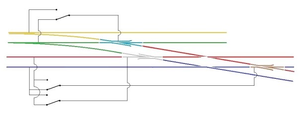
Hopefully this is clear that the crossings on the diamond crossing are activated by detecting the direction of the switch on the approach turnout. If it is set for straight ahead, then a train can’t travel over the crossing and therefore the parallel line can so the polarity of the crossings are set accordingly. Conversely, when the approach turnout is set to the branch, the line across the diamond can be used and the polarity is set to suit.
The principal with the diamond crossing needs to be heeded when the crossing is replaced with a single slip as I have, but it does get more complicated because the switch of the slip can also lead to a different route through the crossings. The crossing to the left of the slip is the more straight forward as it is only activated by the approach turnout. However the right hand crossing is more complicated as if the approach turnout is set for the branch then it always needs to be in the red polarity whereas if the approach turnout is set for the main, then it then needs to be controlled by the slips switch.
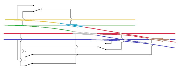
Hopefully the diagram above shows how this works.
The irritation I have, in addition to having wired it up wrong already (!) is that the approach turnout is on a different board to the slip. To reduce the number of wires crossing the boards, I have decided to simply use a duplicate point motor for the approach turnout located on the same board as the slip. It is expensive but rather more simple than the additional wires.
NB – please see also a follow up post on this wiring arrangement for an alternative approach.
Glenmutckin Shed Area
Glenmutchkin’s shed area is modelled on Kyle of Lochalsh’s (it is a mirror image) and I wanted to capture the typically cramped feel of the inspiration. This is the original OS map for the shed (ie old enough to be outside of copyright).
Key to this is the way that the whole complex centres around the turntable and the first turnout is almost tight against the turntable’s wall as this photo extract shows (notice there is not even a buffer stop on the far side of the well):
The first turnout is, you will see, a tandom and whilst it is not visible in this picture, almost certainly it was interlaced (as the Highland always seemed to always use interlaced turnouts). Well, interlacing gets quite crowded on a tandom turnout, as you can see:
It takes a long time to do all of the sleepers as there are a lot of them but once it is done, it does look rather impressive don’t you think?
_________________
Mark Tatlow
No Point Hanging Around
Whilst I have not put any posts up showing progress with the boards for Glenmutchkin, progress is being made and the last two boards are essentially now finished. I am hoping that with one more day’s work which will mostly be to build up a carrying box for the final two, they can all come home.
In anticipation of this, I have been building some turnouts and a bit of the basic trackwork.
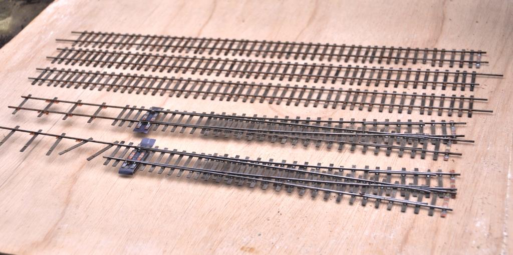
I am only able to do the turnouts which I am reasonably confident will not change shape when the track is finally laid out on the boards. In essence this means the crossings in the bay, the main line and the goods yard. I have also done one of the turnouts in the yard. So seven down, twelve to go including a slip!
I have also developed my approach to TOU’s slightly from Portchullin. As a finished article they look like this:
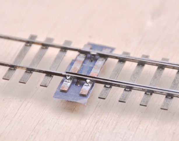
You will see that relatively little of the TOU is exposed (and when it is painted it blend away further). Equally it is much more durable than most of the other options out there because the switchblade is held by both a wire strip but also to some brass strip that is tight to the underside of both the switchrail and the switchblade. By installing this strip in this location, the switchblade is held in a vertical plane much better than other solutions. I think this leads to better running.
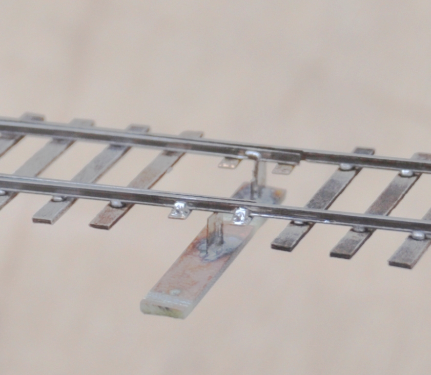
This is what it looks like as it is being assembled. You will see that in essence is it is merely a bit of copper clad below the switchblades, but lowered somewhat further due to the use of the brass strip. This allows the whole lot to be hidden below the boards.
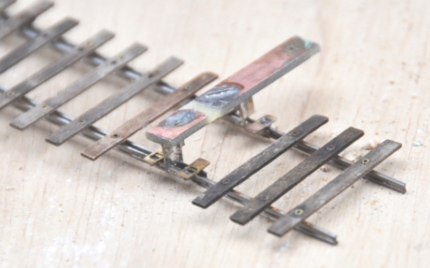
You will note the rather unusual arrangement of sleepers. This is called interlacing and was very common on many pre-grouping lines, including the Highland. I will expand on this in a future posting.
