Blog Archives

At last, a Finished Signal!
Well, that took a while longer to make than I had hoped! Not least because it is not the only signal I am working on at the moment.
Although the drawing did not show a landing in front of the balance weights, i felt that it was likely one would be provided given that these need maintenance at times. Hence this was formed from some L section and an etched slats and provides a useful point to secure the ladder too.
The issue with signals with dolls is that each doll is in effect its own signal; it has a ladder, arm and lamp assembly. But worse than this is that it is also necessary to get the movement to transfer over to the doll so there is even more than a seperate signal per doll. There are a number of ways the prototype used to get the movement to transfer and in this case the signal uses L shaped elbows. Sadly these are more challenging to make as there are more working components and to be prototypical they out to be little more than a couple of mm in size.
A key trick in making signals is to spray paint as much of the signal as possible. Because the components are generally fine any excess thickness of paint will quickly make the modelling crude. As a result of this, I now generally try to make the ladders detachable. In this case there is a rod attached to the top of the doll that a tube at the top of the ladder slips over, with prongs at the base.
So here it is a finished (except for a tie rod which I fortgot to paint so is to be fitted shortly).
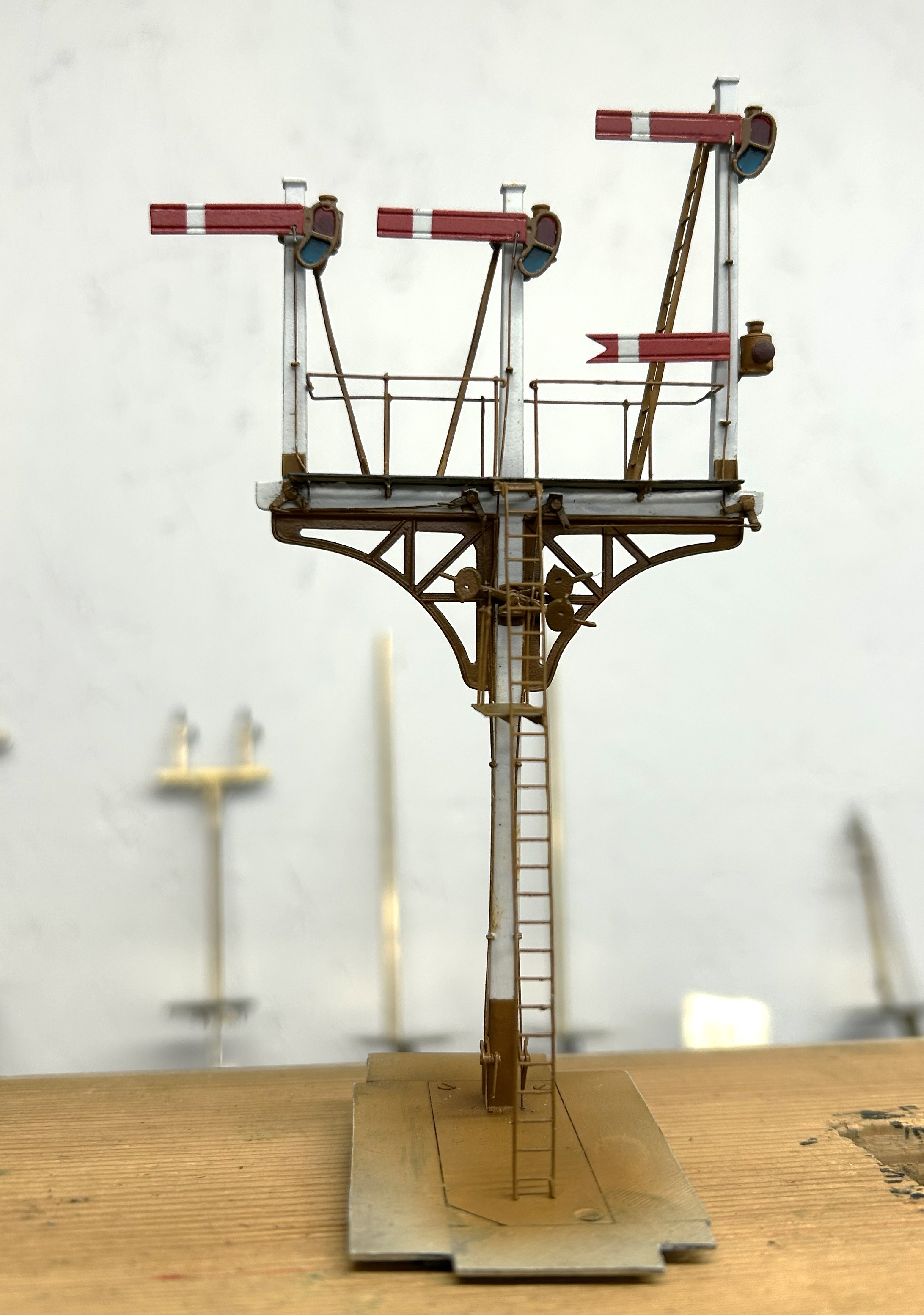
And as is de rigeur for a blog post on the building of signals, here is a video of it in operation.
")
More Seasons Greetings (and Signals)
Having got the post and dolls in place, the next step was to fit the brackets.
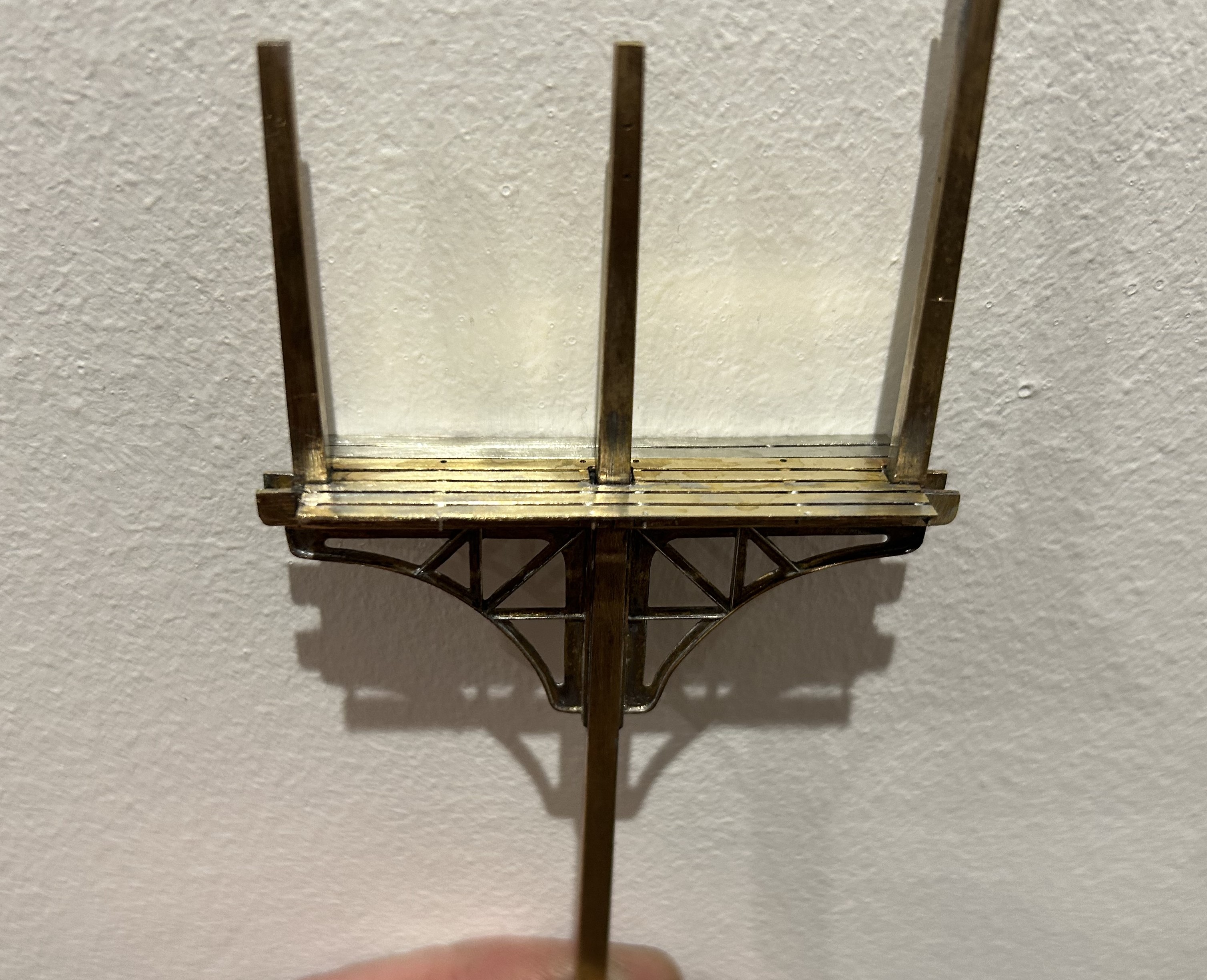
The LNWR were unusual in not using cast brackets; instead they fabricated theirs from sheet and angle iron. Those supplied by MSE are a flat etch and therefore feel a bit one dimensional.
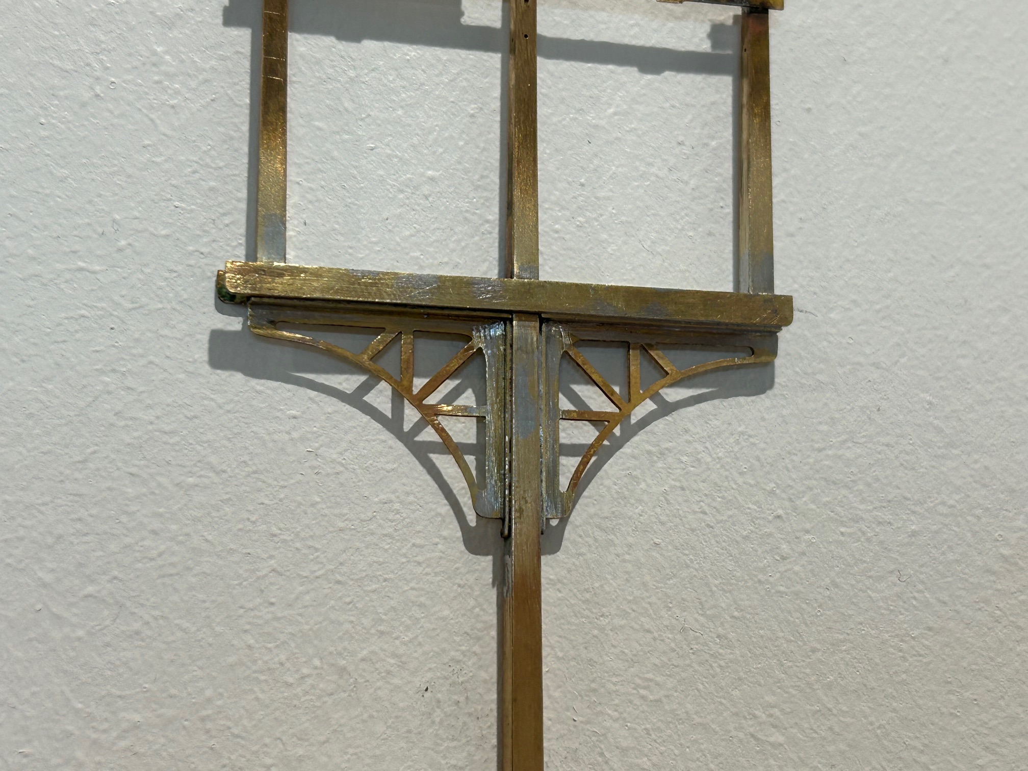
I therefore sweated on brass wire to one side of the strutts on both faces and also a plate on its outer edge. This helps give this a third dimension that was lacking before.

The next issue to be confronted was the landing where the MSE etch only provides a landing to the rear of the posts whereas this (and it appears many other LNWR signals) have landings both sides. I therefore had to produce support brackets and an enlarged area of landing. Foolishly, I forgot to drill holes for the guard rails before assembly, which meant that i had drill them in-situ. This is awkward due to the proximity of the dolls – it cost a couple of drill bits as a result and as a useful reminder to get it right next time!
Next, I diverted my attention to the the mount for the servos. I now always form these with a lower base which is permenantly attached to the baseboard and into which a second detachable base plate is inserted. The two are a tight fit such that once a little scenary is applied to the top, the joint is invisible. These are secured together with 12BA screws to allow it to be detached both during the build and for maintenance but generally it is secured in place. This is because signals are prone to damage when being moved about and would need recommissioning to get the movement correct each time they are reinstated.
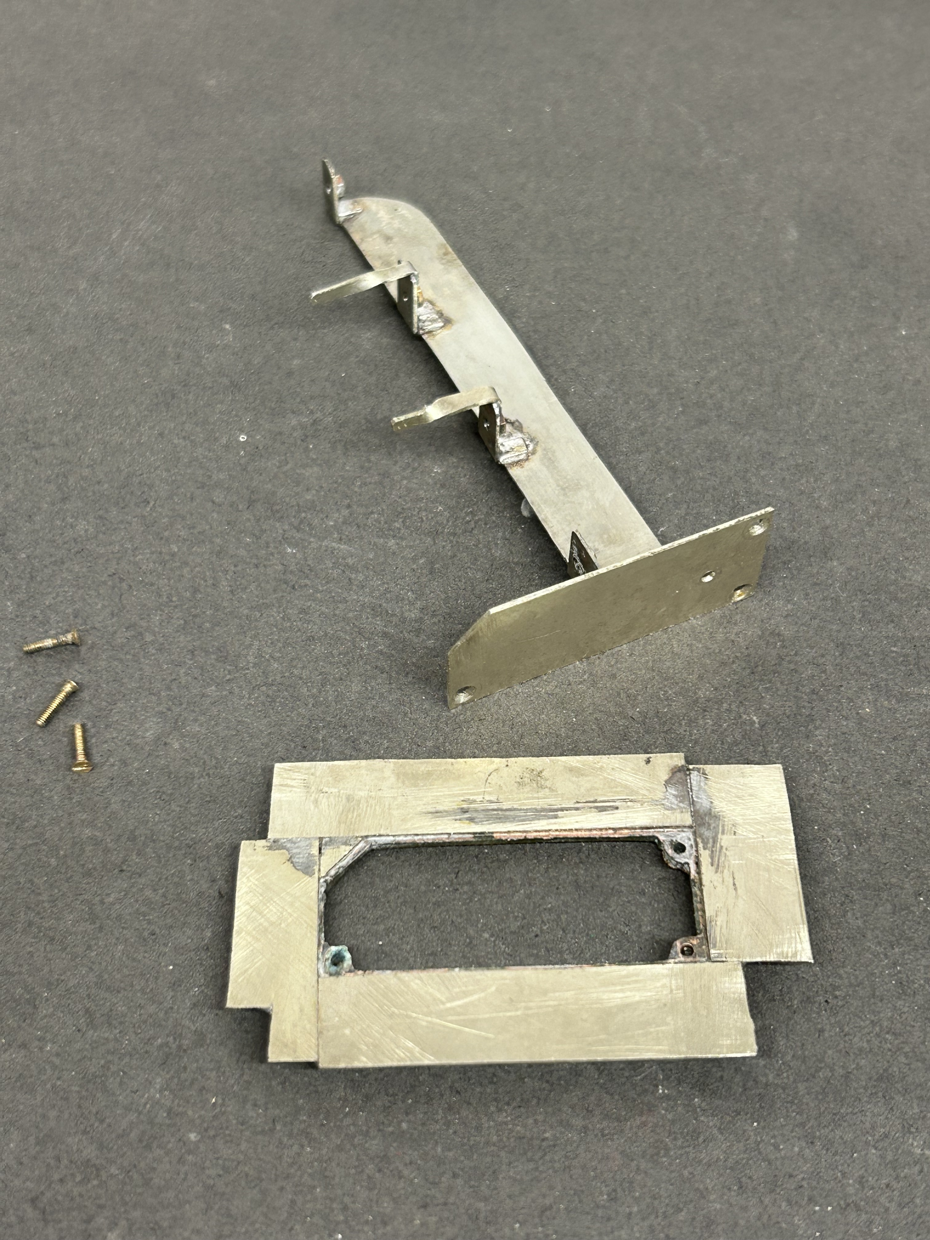
I drilled the underside of the post and tapped it 10BA in order to hold it in place. This enables me to secure it onto the base but subsequently remove it as I build it. I do solder it in place at the end of the build, but the ability to remove it during the build is helpful. The fact that the bolt holds it in place also makes it easier to get the post vertical, rather than trying to hold it vertical simultaneously with the soldering.
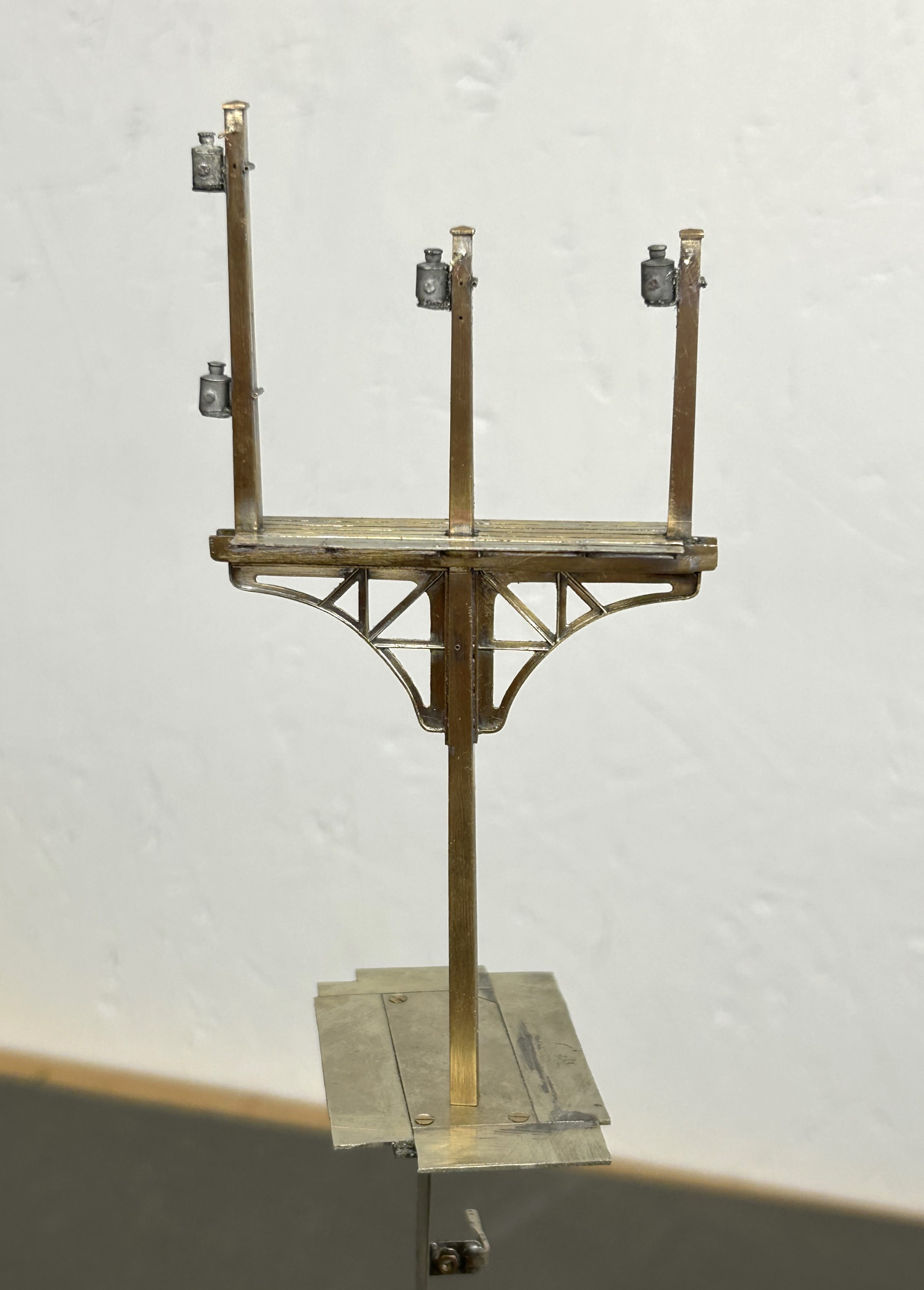
Whilst MSE do provide a white metal casting for the finials, I opted to fashion my own with brass as I find them crisper. To ensure these do not fall away as later tasks are completed, I use a high melting point solder for these and also include a pin drilled into the top of the post. Lamp brackets, lamps, the balance weight mount and some supports for the ladders were next.
I now have a recognisably signal beginning to form but the difficult bit, the movements are still to go.
")
Seasons Greetings (and Signals)
Work (at least real work) is now over for 2025 so I can get a bit of time in for turkey, mincepies and, of course, some signals.
I have built up a number of promises to make people signals; more than enough to keep me fully entertained for not only Christmas but quite a lot of time afterwards! It is time to start delivering on these promises.
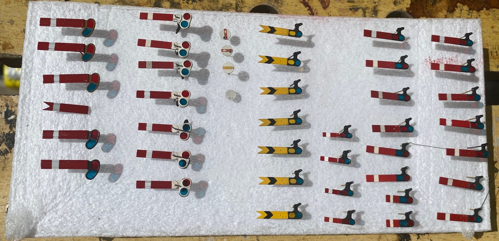
First uo has been to paint the arms. I know do these in advance as there is a lot of effort to paint them well and the best finish is by masking and spraying most of the colours. I can’t seem to brush paint to a good enough standard. I do, however, form the black shevron on the distant signals with black transfers as it is difficult to mask this neatly and the bars on the ground signals are a transfer from 51L.
I should be busy with this lot…………
In another departure, i have borrowed a milling machine to assist me in making the tapered timber posts. I form these from 4mm square brass section, a selection of files and a lot of elbow grease. It is a chunk of work for one signal but I have six taper posts and eleven taper dolls to do – I am not sure i have enough elbow grease to do this many!
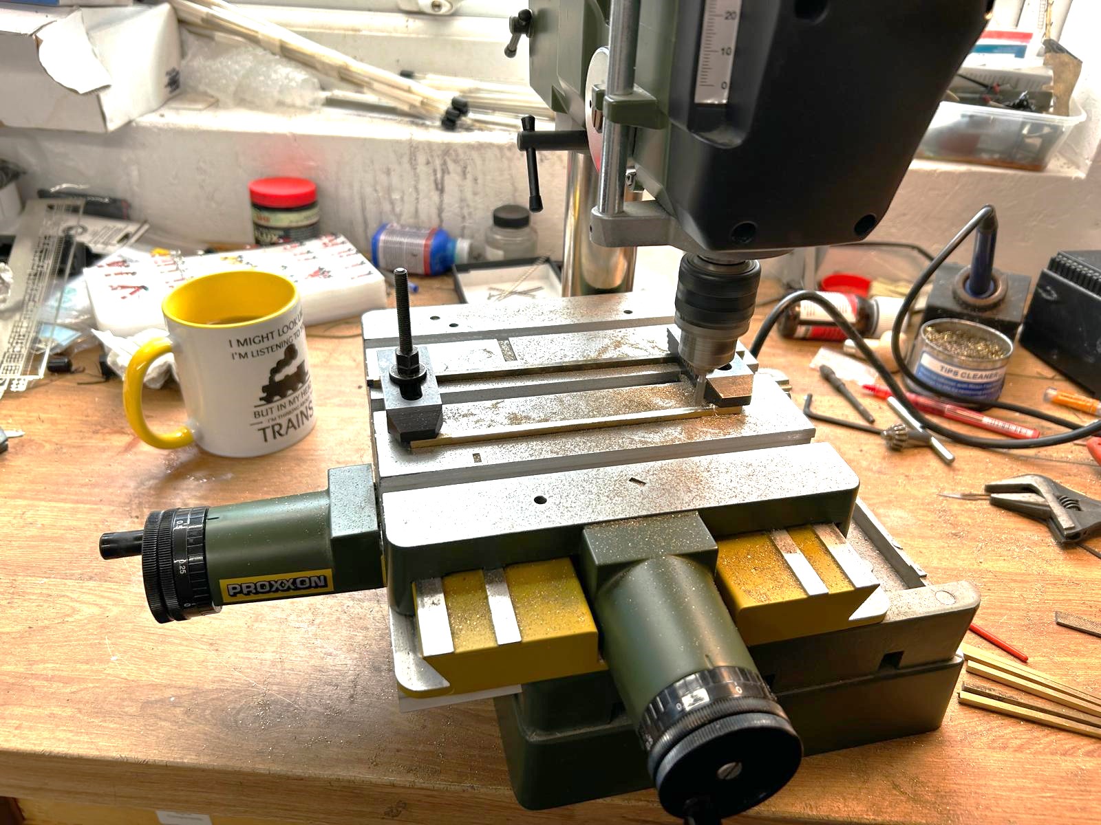
I propped one end of the post to form the correct taper with the mill travelling level. it was not without problems as the brass tended to flex (upwards oddly) where it was not supported. I ended up using the mill to take most of the weight off the metal and then went back to the files to finish the task off. It does reduce the effort, but it is still hardwork – and i have only done half of them so far!
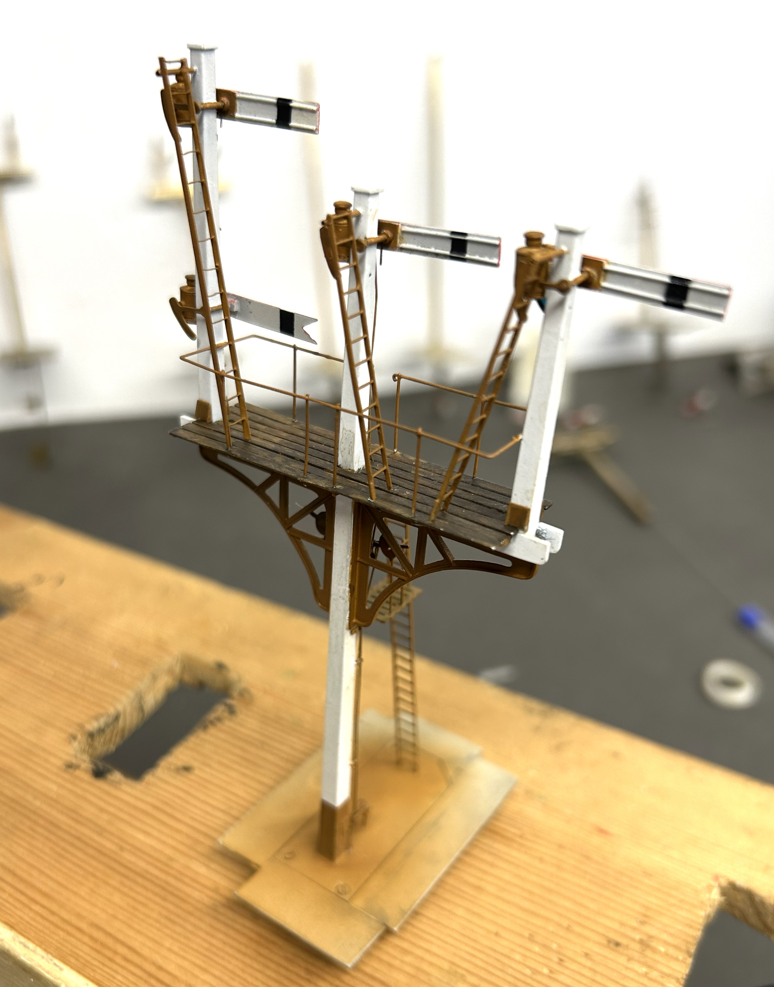
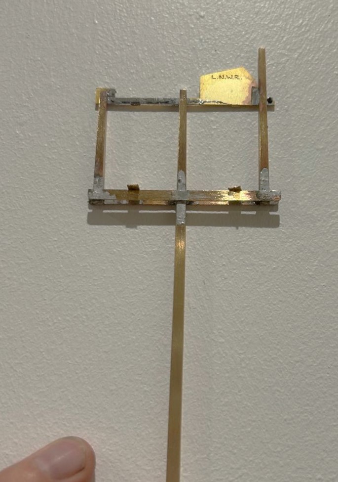
The first signal up is a LNWR three doll signal with three moving arms plus a fixed distant. Nearly as shown in this official drawing.
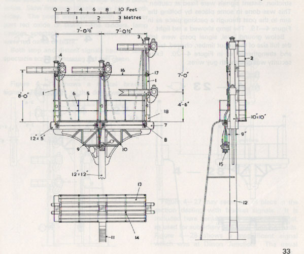
The basic posts and dolls are now in place; with various scarp etch temporary strutts to keep it square. Still a long way to go though!
So i wish you all a great Christmas and a Happy New Year.

What Have I Been Doing…………..?
Gosh, another year where my intentions to increase my rate of posting have got away………..
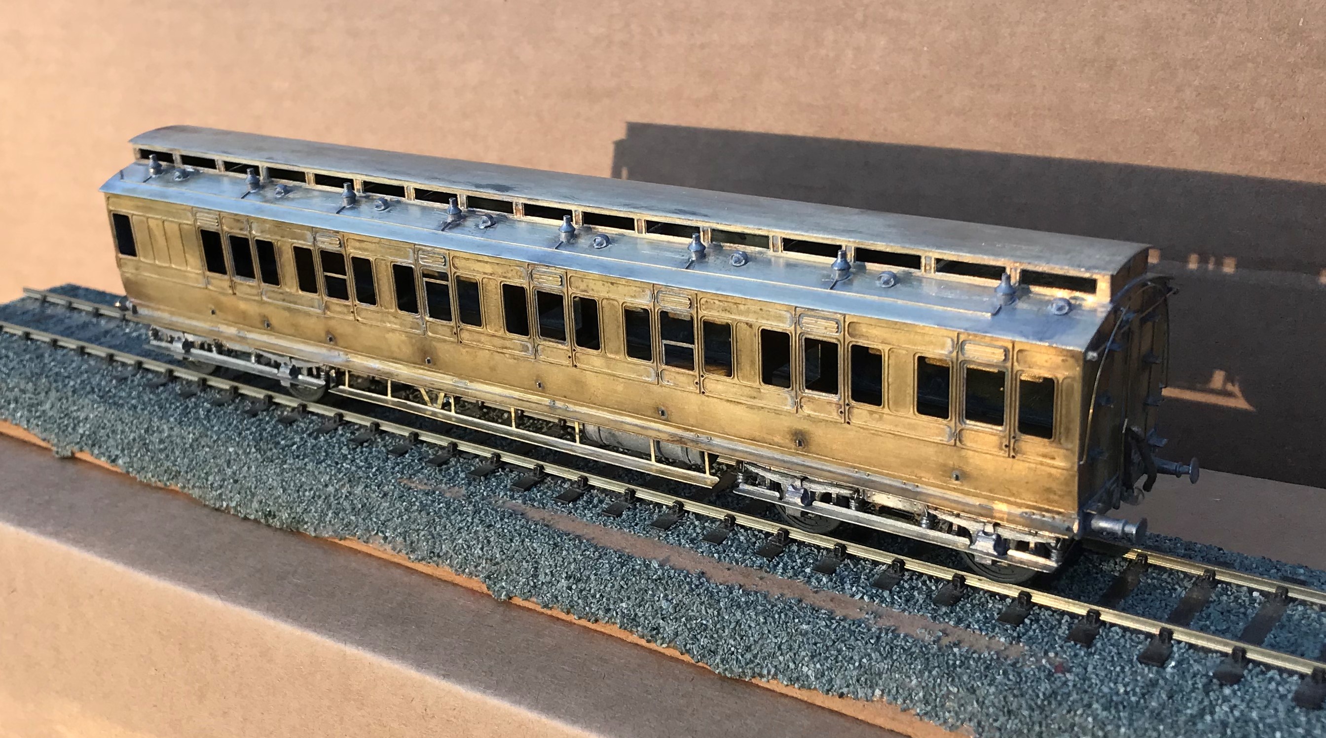
Whilst work and home life have intruded, I have still managed to get some modelling done; including a rake of NER coaches for John James for which i do get something in return in due course.
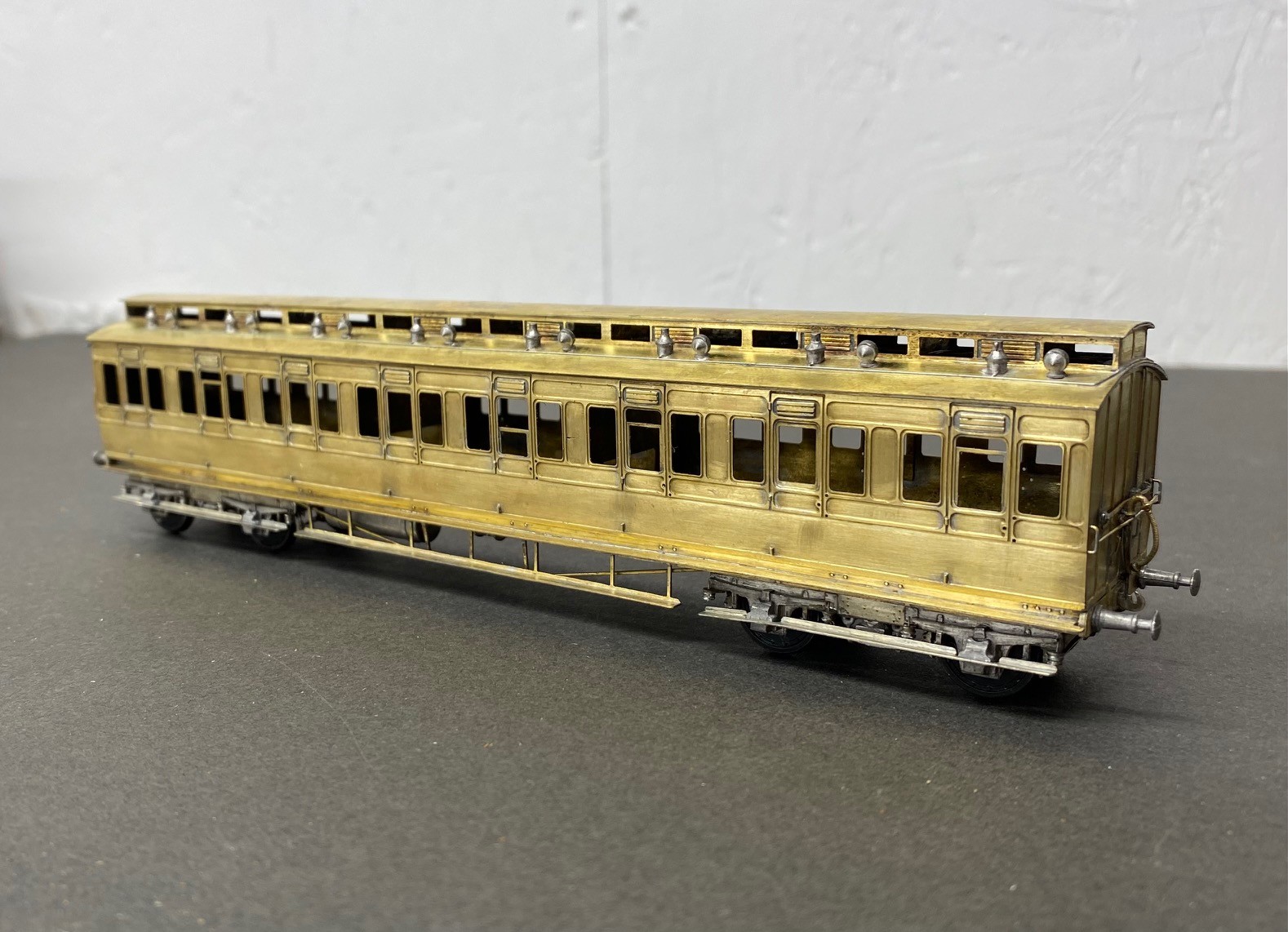
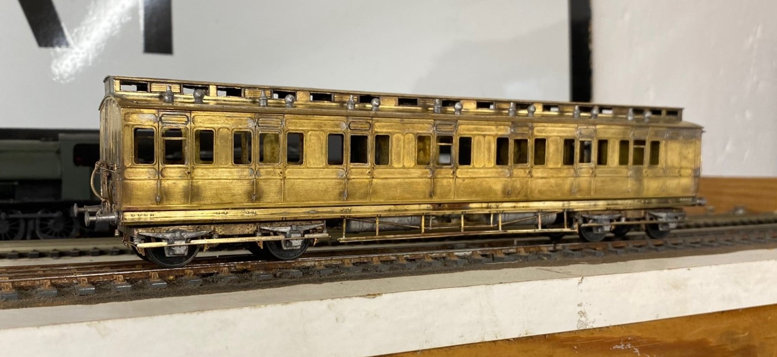
The rake had a pair of three compartment thirds, of which this is an example:
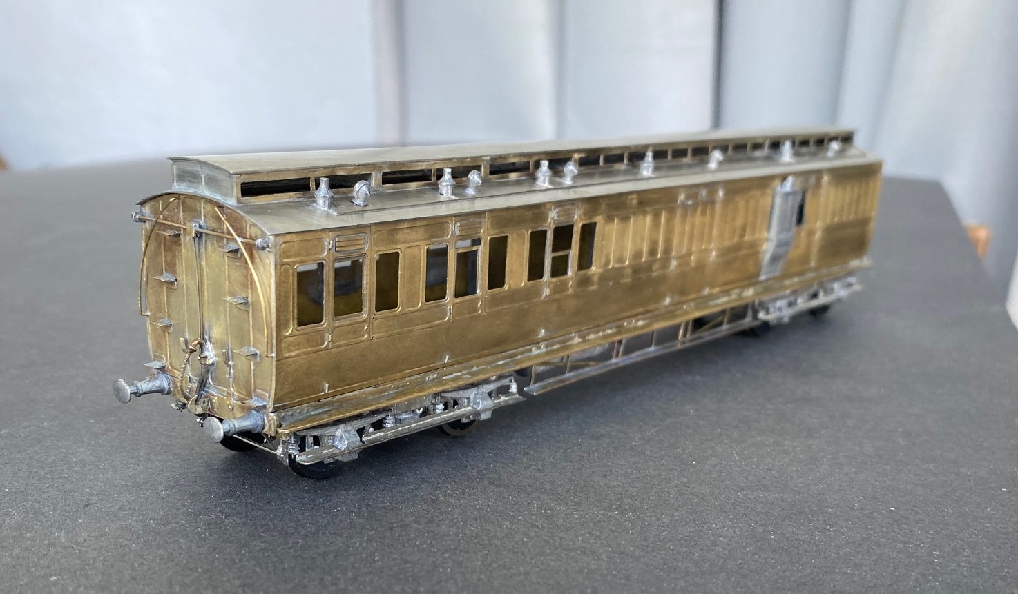
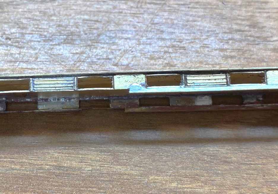
All of the coaches were constructed from D&S kits on my Miscellany Models Fox bogies with replacement roofs formed of nickle silver sheet. I find that the plasticard offering in the D&S kits to be their weakest point. The problem with this is that if you make your own roofs i find you might as well also cut out the section below the clerestory – it makes a huge difference for the coach to be illuminated from above. The issue is, that there is a lot of work in these roofs – I found that for each there was 15+ hours of work just in the roof!
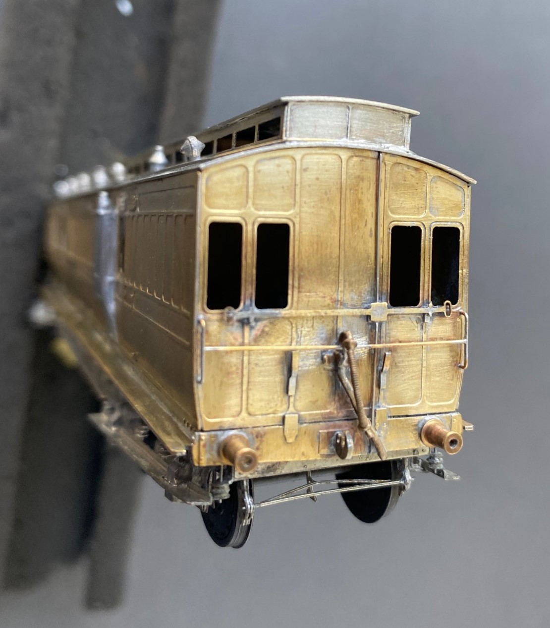
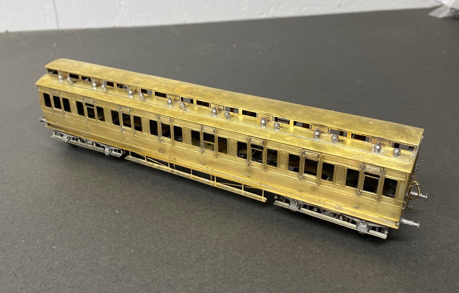
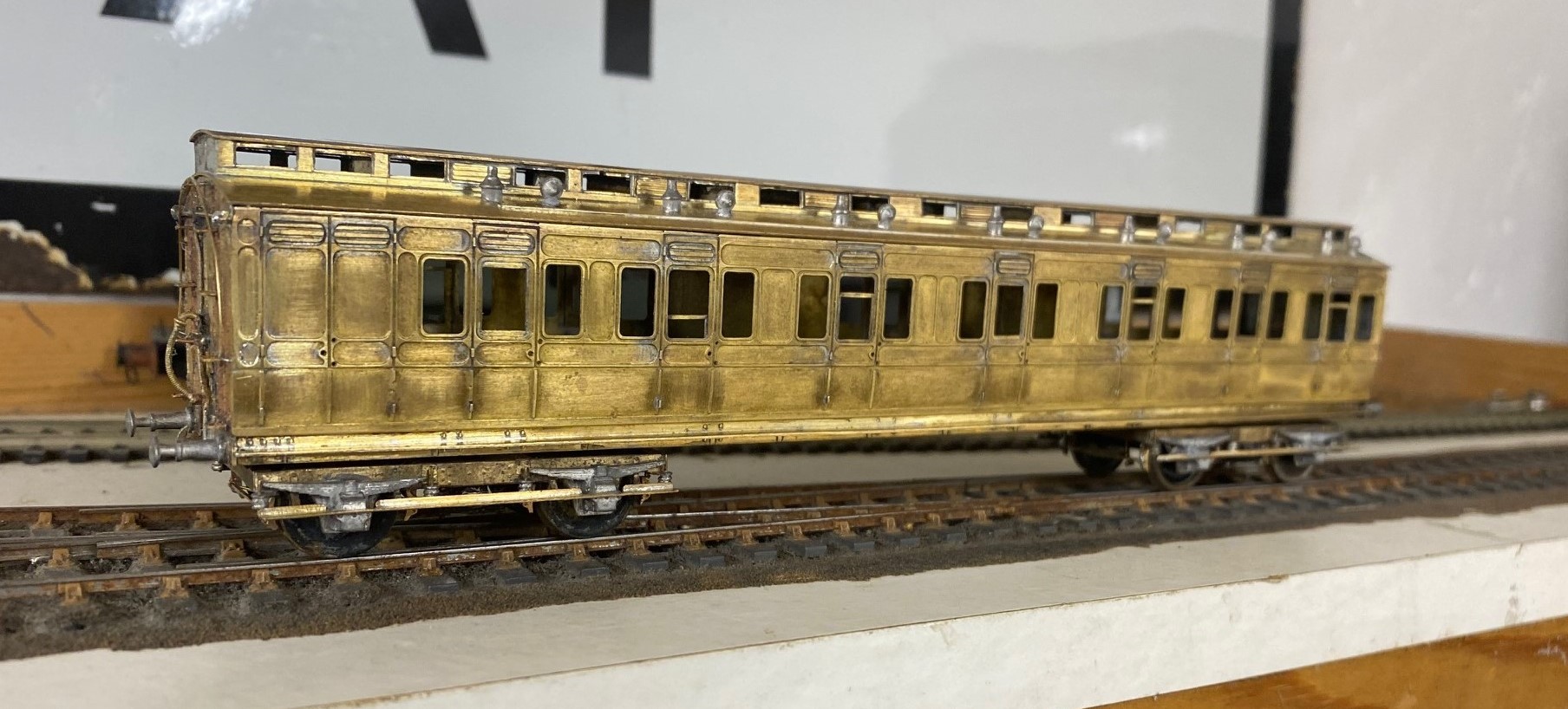
Also in the rake is an all third, which is probably my favourite of the build as it feels quite “pure” and also wihtout the problems of the composite…….see below…….
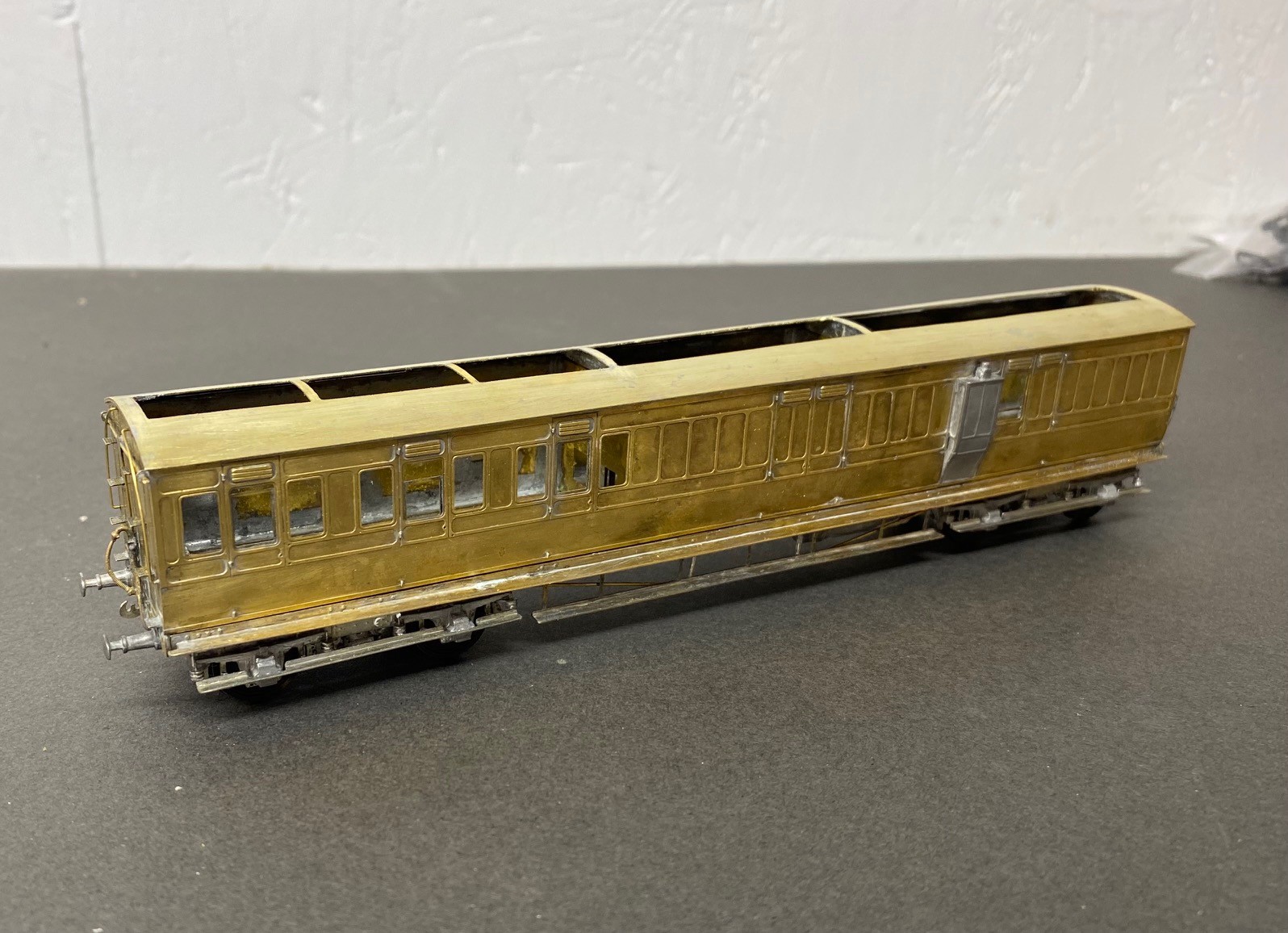
The rake only needed a modicum of first class accomodation made up from a composite diagram 7. Alas, this had a challenging problem that needed to be overcome, with the clerestory side pieces. These were much shallower than those on the other kits orwith the ends supplied in this kit. In addition to being obviously incorrect given the inconsistancy but the frames around the glazed lights were stunningly delicate. I regret persisting with this, i should have just drawn up some replacements in CAD and popped them in the next etching order.
However, i solved the problem by soldering a flat strip, 1.5*0.5mm along the base. in theory it should be to both the top and bottom but that was not realistically possible and I decided life was too short. After much fighting, cussing, fighting, screaming and more fighting, I did get it there, as I hope you can see.
I was asked to do these as gas lit coaches and therefore there is a bit going on below, as one might say.
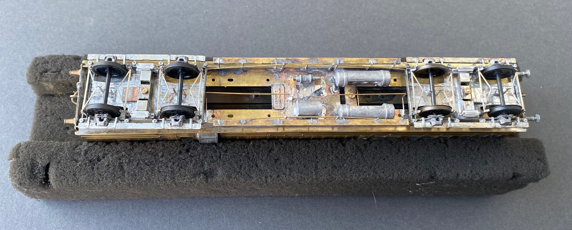
As the coaches were quite long lived, they went through many detailed changes. for anyoen who is contemplating building some, I would heartily recommend reading David Addyman’s notes on how he built his in the Scaleforu Forum https://www.scalefour.org/forum/viewtopic.php?f=39&t=7210&p=101662&hilit=ner+coaches#p101662 David’s coaches are modelled in the 1930s, so have different lighting arrangements, footsteps, bogie spring dampers and sides to the clerestories. Lots of things to be aware of if you are doing something similar.
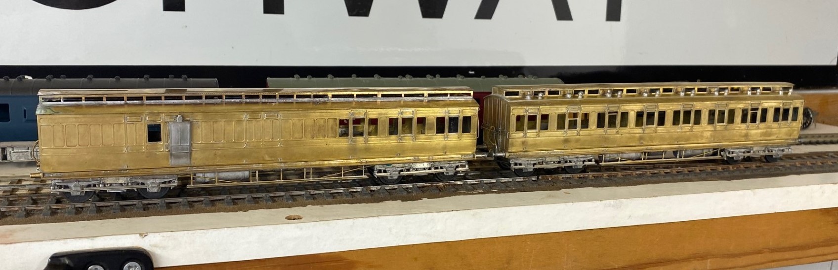
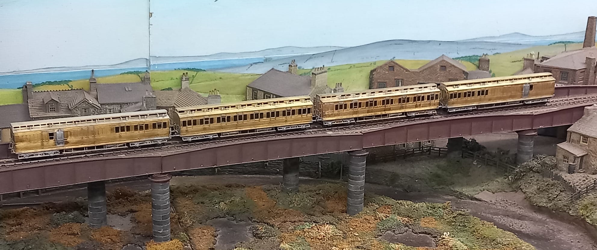
At the end of this rather mammoth build, I had four coaches that i was rather proud of. They look rather fine on John Wright’s Benfieldside viaduct.
I am also pleased that i do not have to paint these; i am still looking for my lining mojo. I had it as a teenager, but have grown shy of lining. Maybe something for the Christmas break?
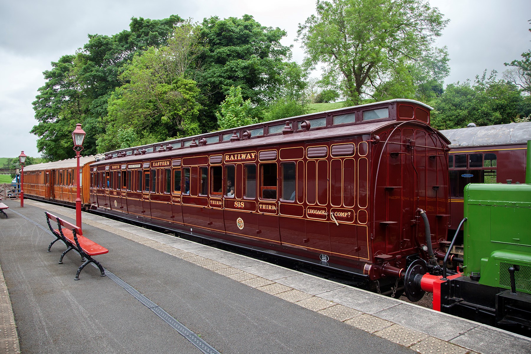
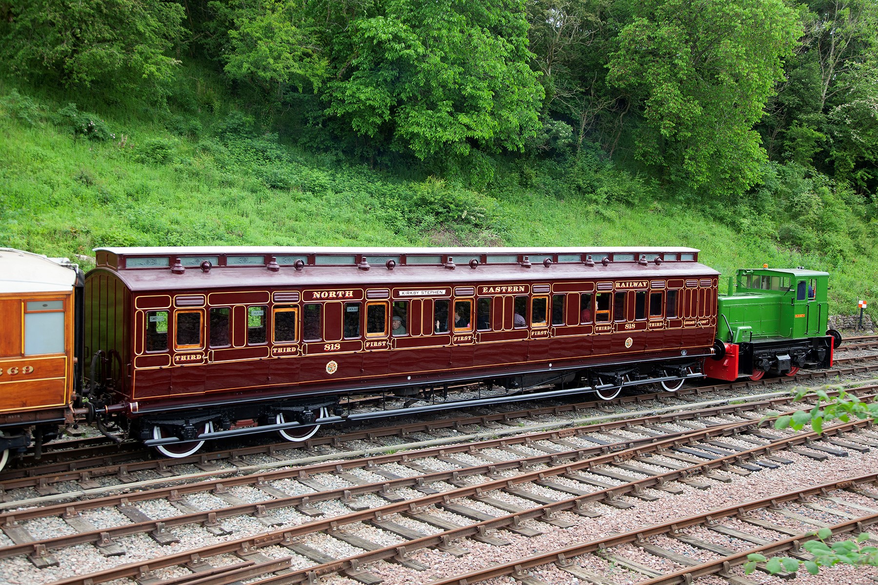
In the meantime, here are a couple of pictures of the newly restored NER coach 818 at Kirby Stephen, courtesy of the Beamish website. Does’t she look magnificant? I really must get up to see her.

Delayed Delivery – Part 2
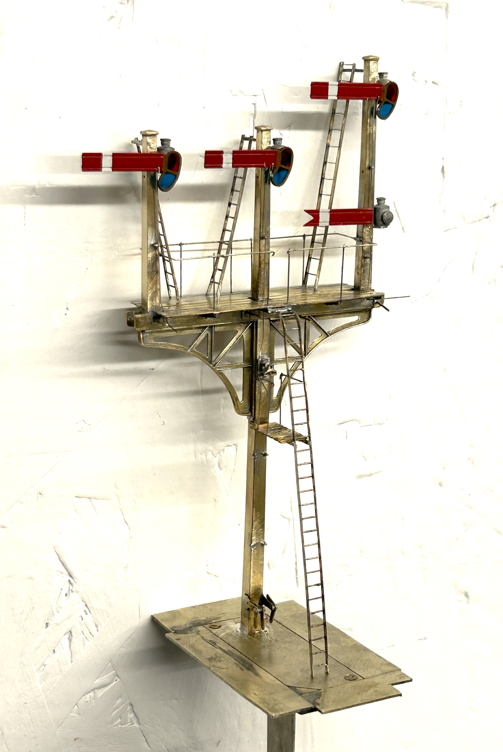
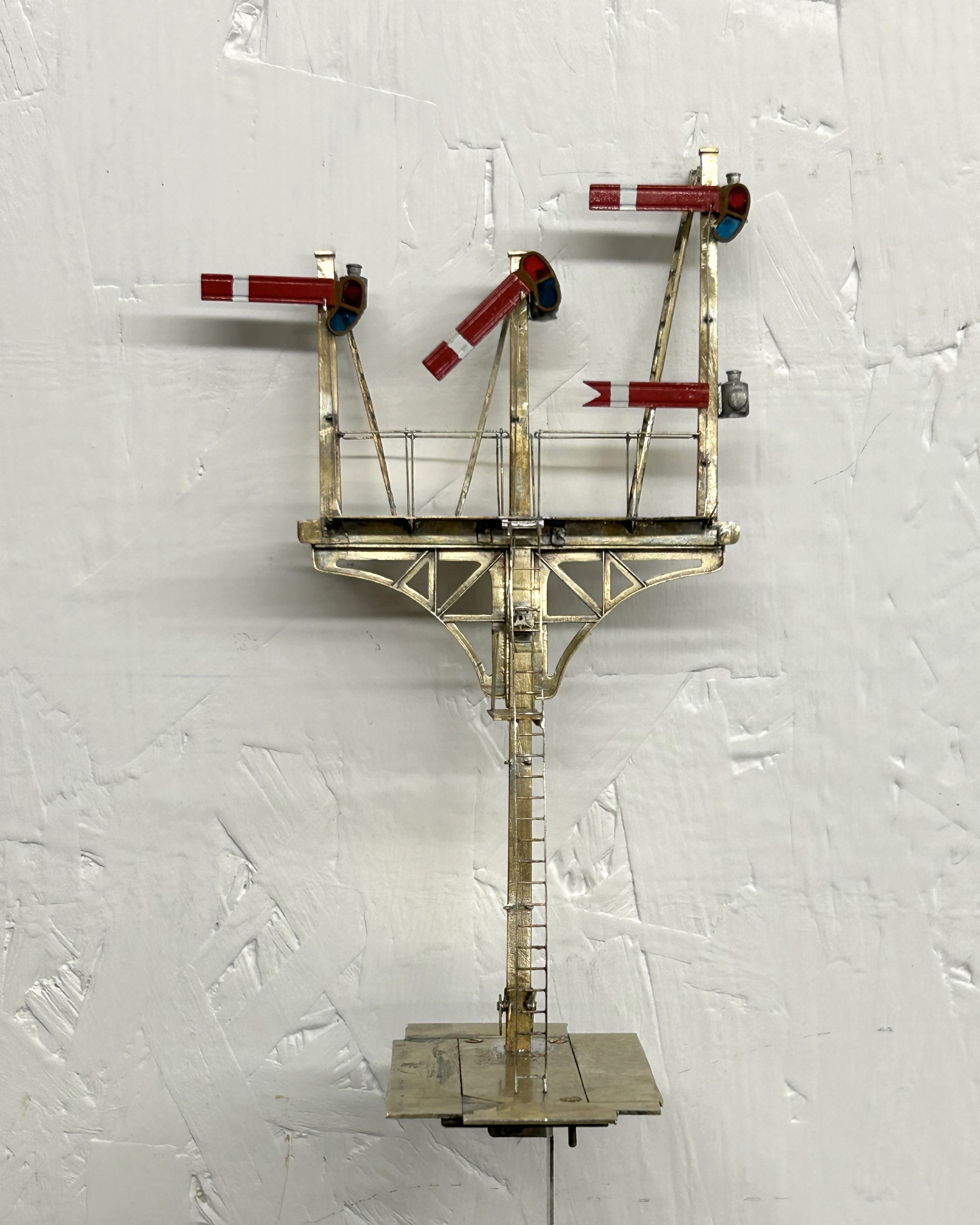
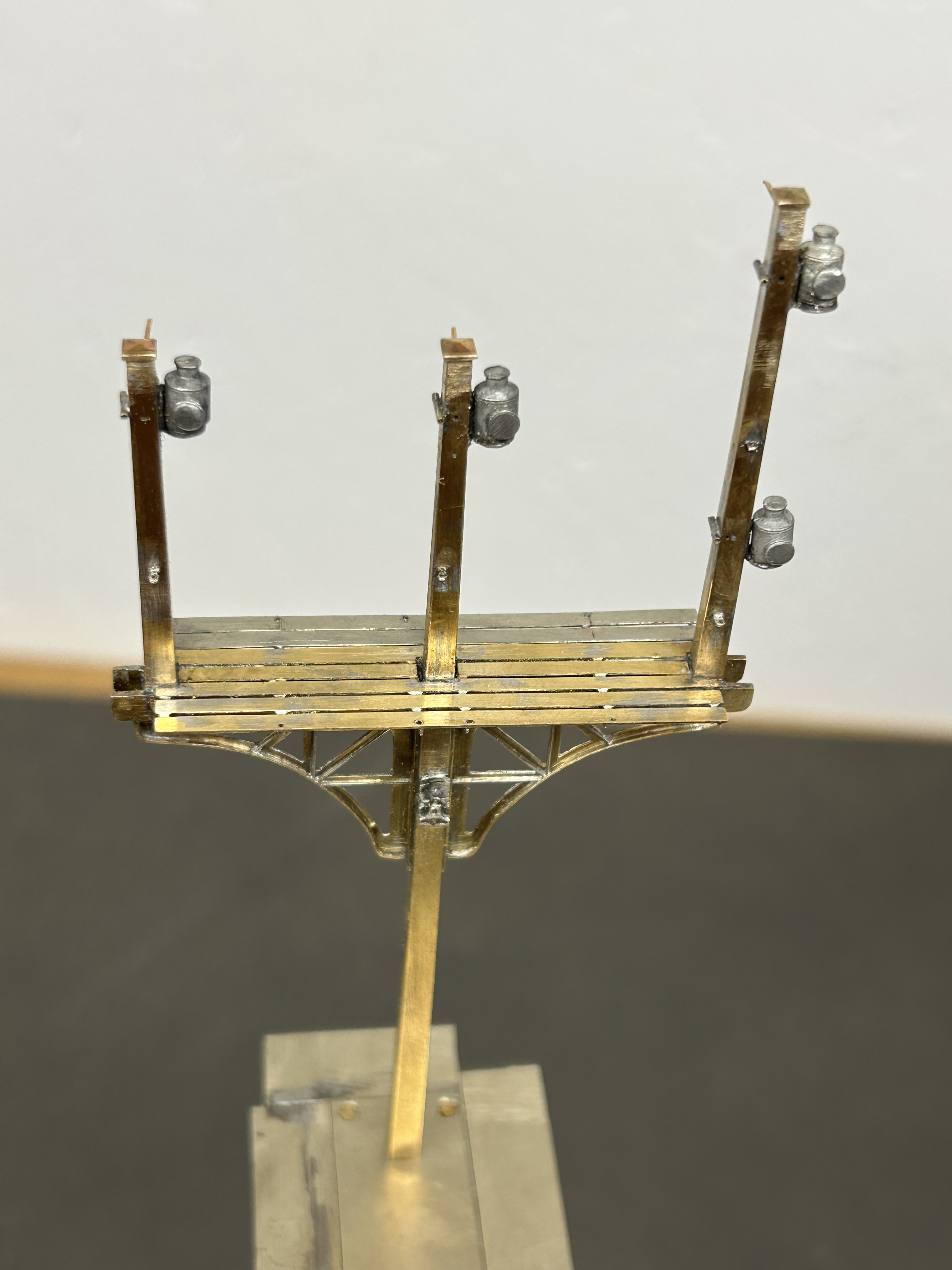
Once the basic structure of the gantry is in place, the real task of making the signals signally commences. First up were the smoke deflectors and the brackets for the balance weights. Also fitted are the main portions of the fan route indicator, but that will be explained further once I get it going!
For the arm bearing point and lamps I am using some 3D prints produced by Steve Hewitt and available from Shapeways. They can be found here https://www.shapeways.com/product/JJRSB … arketplace. They are fairly expensive but they are neat and save a lot of manufacture. There is, however, a but – they are very delicate and I am very fearful of thier long term durability. I am highly likely to draw some of my own up and get them cast in lost wax. It will make them even more expensive but I have about a 50% casualty rate at the moment, so maybe in the long term it will be cheaper!
The arms are Masokits, these are definitely the best available arms for LMS/LNER/BR semaphores. This is especially true of the minature shunt arms as the MSE ones are simply too delicate to bother with (imagine how do I know that………….!). So this is where we are now at with the arms mounted temporarly on the bearings.
There are five movements in the down direction (three of which operate via the route indicator) and then a pair in the up direction – hence the back to front arms.
The plates at the top of the dolls are mounting points for ladders. It transpires they are wrong and have already gone!
So the intensity level has dialled up a notch with these portions (especially breaking the bearing/lamp fittings) but it really gets interesting when you try and make these things work.
I don’t know myself yet (although I know for the couple of arms I have finished, so I have an inkling), but i think it might be fun to have a little sweepstake on how many moving parts there will be in the finished gantry. Five arms, three fan route indicators and each is operated by way of angle cranks. Each arm, crank and intermediate wire counts as a moving part, as do the servos………………..guesses please?

Delayed Delivery – part 1
After a long pause, caused by that irratating thing called life getting in the way, I am looking to deliver on some long made modelling promises over the holiday season.
The major task is a rather full on gantry signal with no less than eight movements on it (which is an improvement, when initially designed it had nine!), including a rather natty fan route indicator. This is for a friend’s layout and is in return for some signal cabins that he built no less than 15 years ago – I told you the promises were long made! Mind you, he hasn’t got the layout fully running yet, so I am still ahead of him!
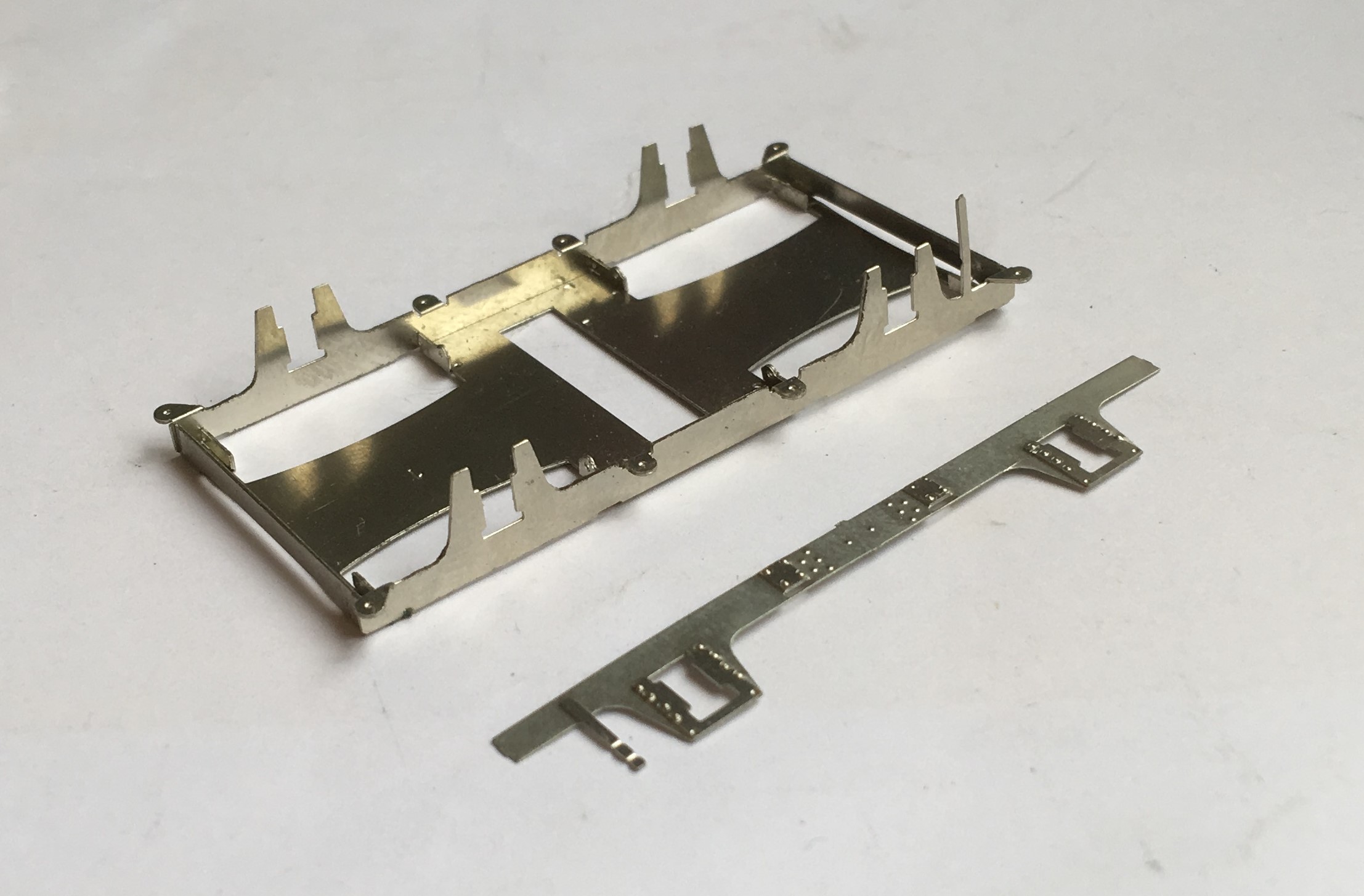
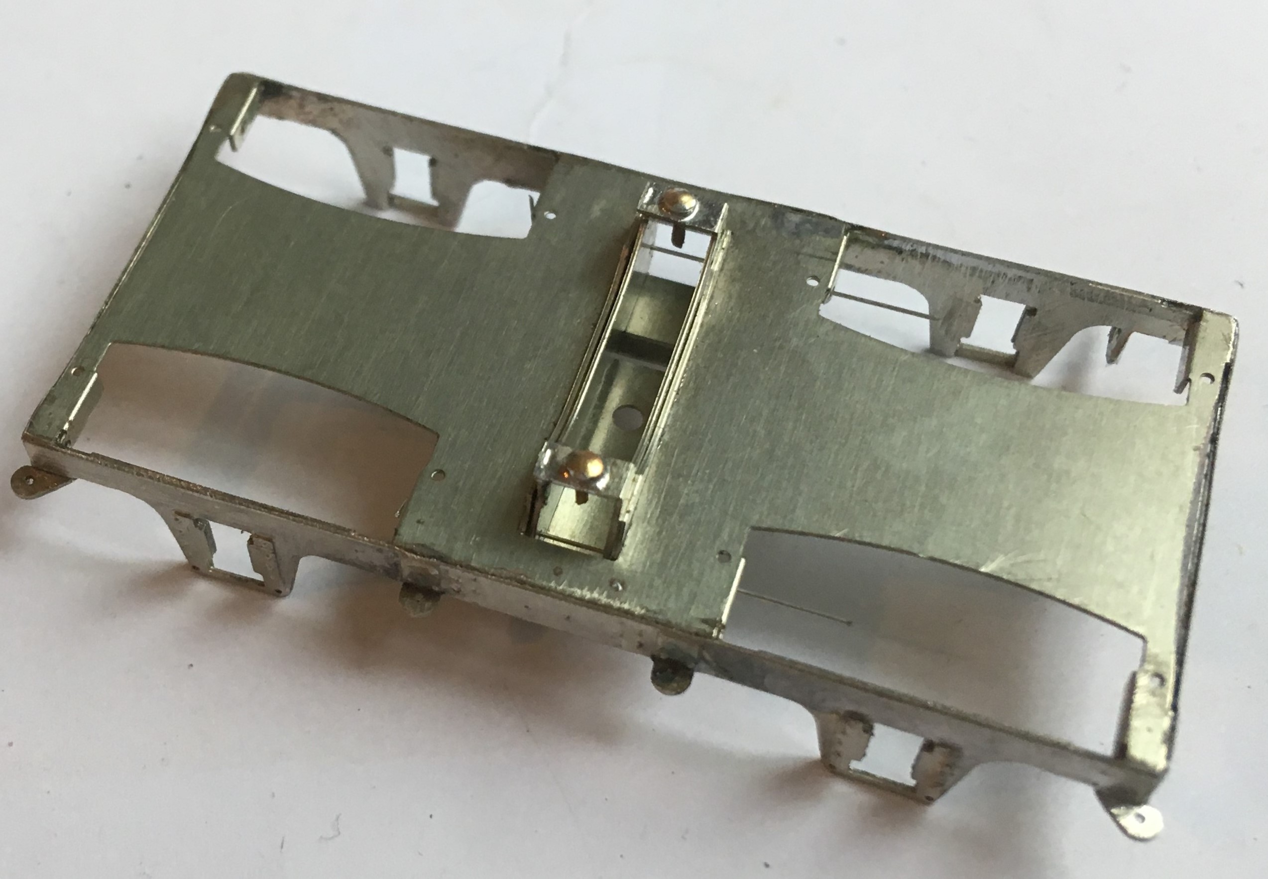
The gantry spans only two lines so it can be formed with channel section. There are good drawings and pictures in LMS Journal no 5 of this. I have made mine from milled brass section and then the landing was a custom etch I designed as it takes a surprisingly large amount of material and effort to construct this from scratch. These etches included the doll base plates although the dolls have a thickened tube at the lower level which of course I forgot and had to undo later work to put on!!
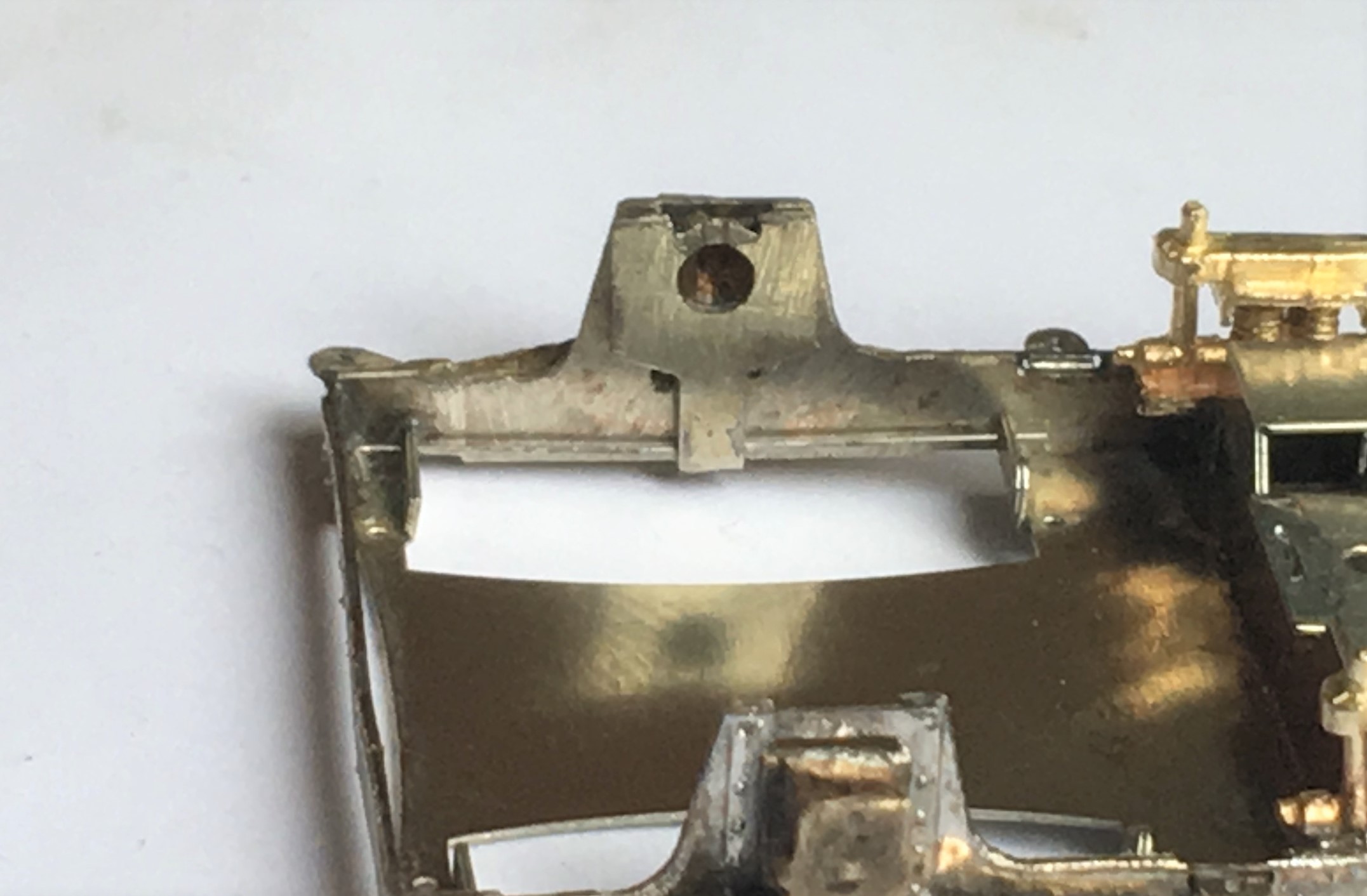
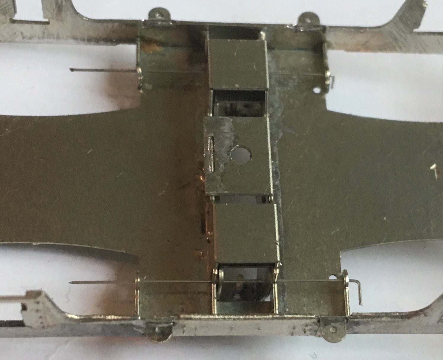
The signal is to be located on an embankment which meant that I could not simply put flat base plates on the foot of the gantry columns. Instead I have constructed a housing that matches the slope of the embankment and then the baseplates are partially sloped to match this with square sections representing the foundations of the prototype columns. Below these baseplates I have then formed housings to take the servos which will eventually operate the arm actions.
So far, this is pretty easy modelling (although I lost a number of drill bits opening up the stanchion positions on the landing – grrrrrr!). The tough bit comes next……………
There are potentially two viewers of this thread who might be thinking that I have long outstanding modelling promises to them too……………I am also working on one of these too!!
The Other Auto-coach
Some time back I posted about the construction of a NER autocoach that I was building for Benfieldside and subsequently what it looked like once painted by Warren Heywood.
The NER generally used these in pairs, with a loco sandwiched between, although they did go out singly and even as quads. In this case, the Benfieldside team wish to operate them as a pair, as the bay to the right of the layout is conceived to receive such a train, with a NER / LNER G6 in between. This means that there was pressure to build the second from the moment I handed the first over. They have recently given me a favour, so it was high time I repaid it.
It is now completed down to the final check over stage (which has indicated that I need to put the steam heating pipes on – doh!) and then it can be delivered. So I have braved the fading light this afternoon (so sorry about some of the depth of field issues) to take a few pictures and to prove to the fellas it is done!

I completed a few personal upgrades to the kit in both this and the earlier autocoach. Chief of these is around the roof where I ditched the plastic roof and replaced it with rolled brass. This was formed of 0.25mm to give it a tangible depth, which makes its rolling a fair challenge. Add to this, I elected to cut out the portion below the clerestory, so that it was a clerestory! By the time I had added the gas lines and the various gas lamps and ventilators, I reckon there is around 20 hours in making the roof alone!
The prototype coaches were fairly long lived and numerous. They thus collected a good number of alterations and differences over time. I took some guidance to David Addyman and tweaked the kit in respect of gas lines, foot steps, handrails, footboards and gas cylinders. If someone thinks this is wrong, please don’t tell me!!
It always amuses me that the driver had to stand and peer down the line through two tiny windows. They lived in different times – could you imagine the snow-flakes tolerating this in the 21st century?
These are rather beautiful coaches, but not for the feint-hearted as there is a lot of time invested in these. I am pleased I do not have to paint it!

News from Miscellany Models
Followers of this blog will have noted that various test builds of my artwork coming together and I am now able to offer a number of these for sale under the name of Miscellany Models.
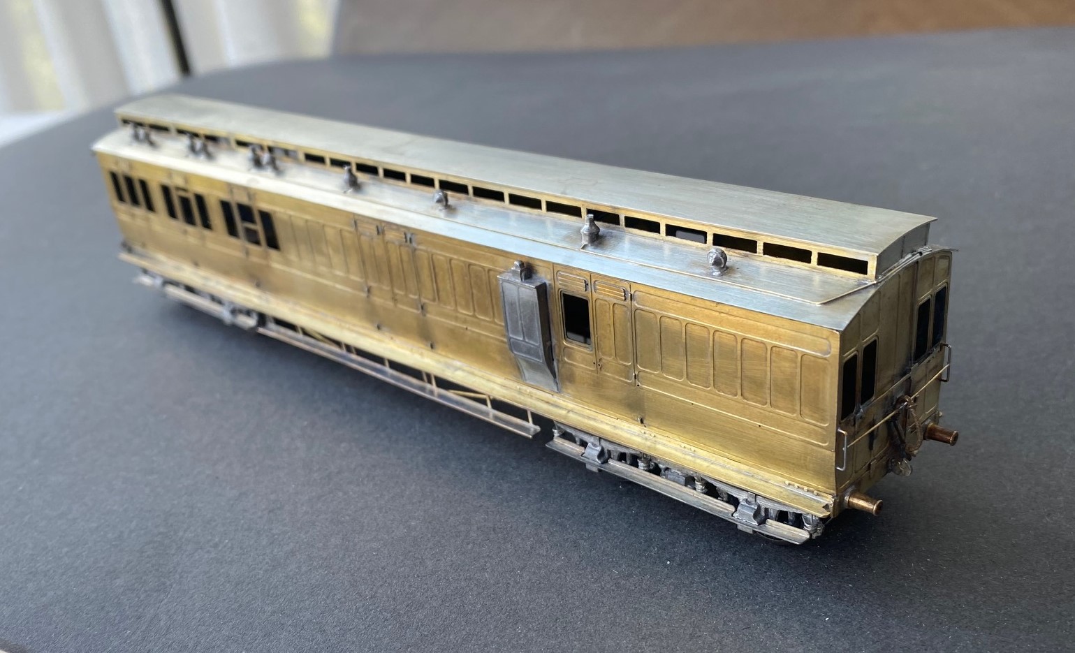
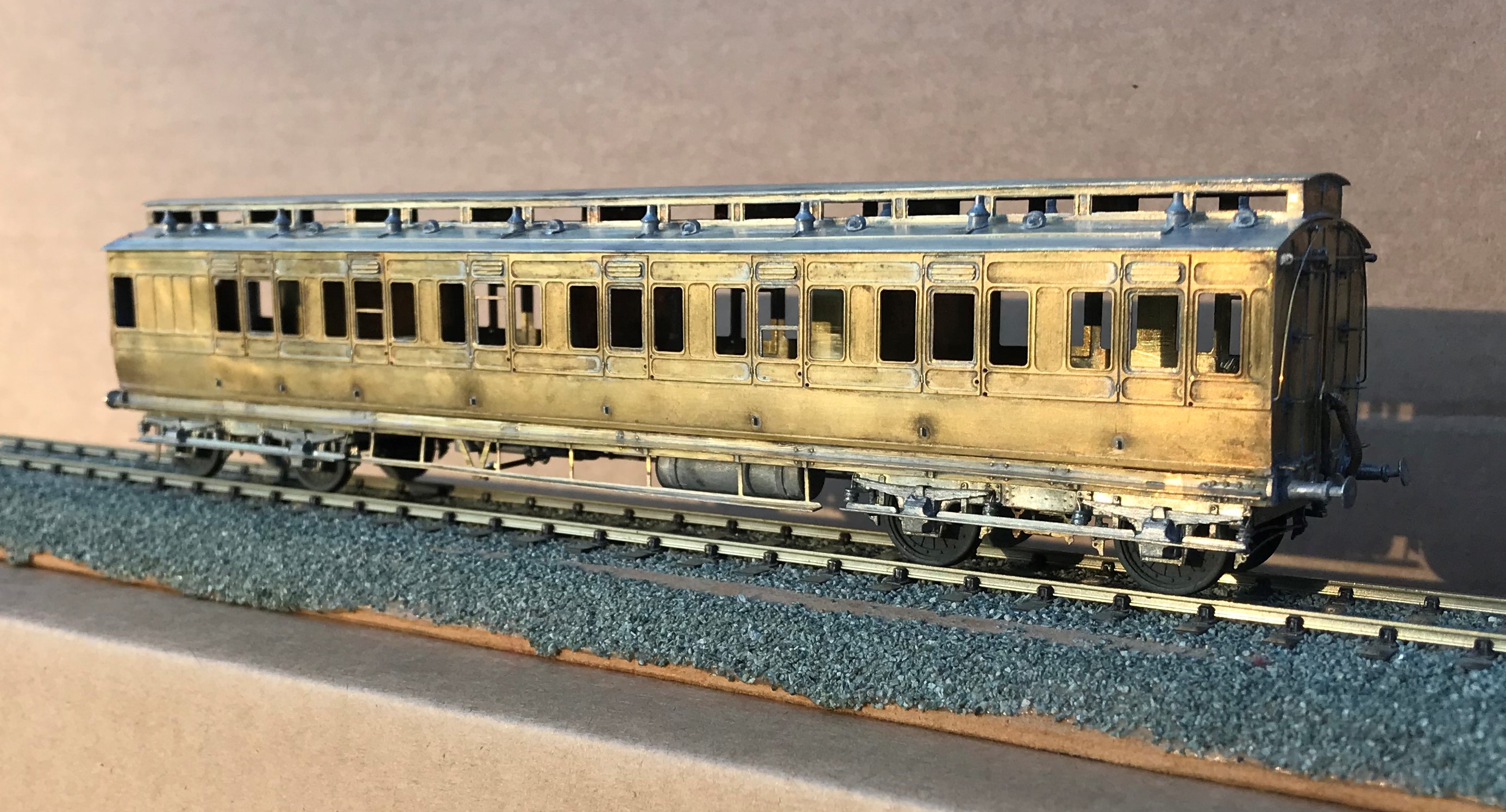
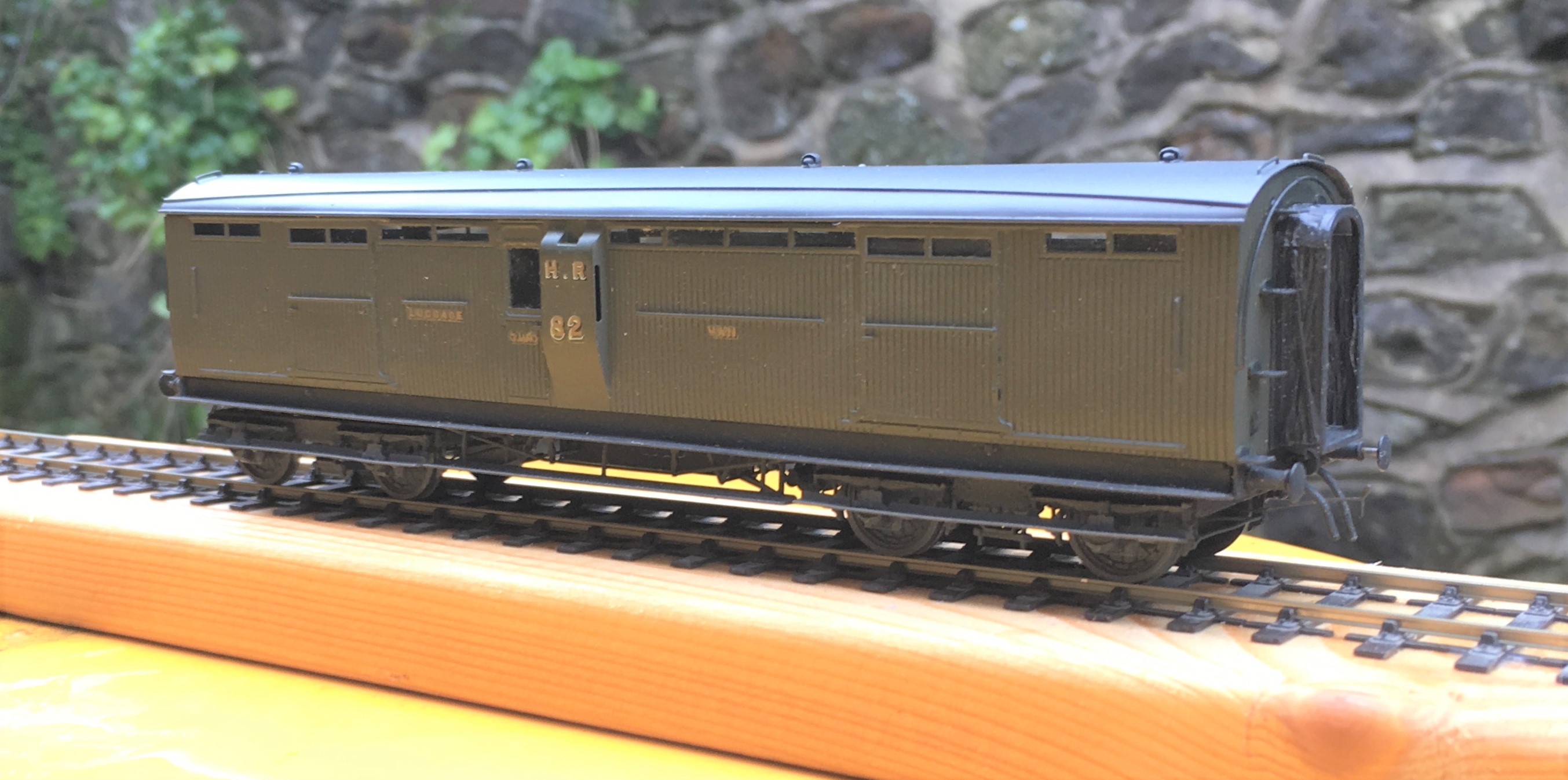
First up is a Highland Railway/LMS/BR diagram 51 full brake – priced at £48.00 for a 4mm and is suitable for OO, EM or P4. These were the last generation of full brake produced by the Highland, built with both cupboard doors and sliding doors as well as alternative forms of guards duckets (all of these are included in the kit). The kit inclusive of fully sprung Fox bogies (see below), roof, corridor connections (also see below) but all castings and buffers will need to be sourced separately. The castings for the bogies are proposed, but are not presently available.
As was common with many pre-grouping coaches these vehicles utilised Fox Bogies (£16.00) and these are being made separately to the remainder of the kit, These bogies have been developed in conjunction with Justin at Rumney Models and are fully sprung, with both the axleboxes and the bolsters sprung. They really do glide across track and look as if they weigh many tons rather than a few grams! They need castings for your favoured axleboxes/springs and bolsters but do include the foot steps and all of the bogies sides, brakes and details. Suitable for oo, EM and P4.
.JPG.3b26712c4490ad68695b10226612a0a9.JPG)
The second coach kit is for a MR/LMS/BR: Dia 530 Passenger Brake – priced at £36.00 in 4mm scale (suitable for OO, EM and P4). This prototype was built in some numbers and by the 1920s they were spread extensively across the LMS system. The kit is for full etches covering the roof, body, underframe and footboards plus parts for the sliding central axle included. It needs axlebox/springs (available from Branchlines or Coopercraft), gas lamps, buffers, brake and gas cylinders.
.JPG.1678157932a192d68328755d825c54f0.JPG)
On the wagon front, there is an etch to detail the NER/LNER/BR: Dia P7 Hopper Wagon – £13.50 4mm (sufficient for two wagons). They cater for a large number of the variants to this numerous and long lasting hopper wagon. Needs wheels and the Slaters kit P7 kit for the donor model. Variants that can be made include the end braked version, improved components for the Morton braked version, outside twin W irons and also the anti-friction wheel device.

All of these are available from my website https://miscellanymodels.com/ and in addition to this from the Rumney Models stand at the following shows – Scalefour North in April, Railex in May, Scalefourum in September and South Hants in November,
All of these have been extensively road tested by me with a couple of test builds for each of them. You can see this unfold on my blog and if you are interested in seeing how they go together do take a look!
Please remember that the availability of these models is an adjunct to my own hobby and this has to be accommodated within the constraints of my day job and general life! In particular I can’t get to post these orders until Saturdays so do please give me a little slack when it comes to getting the goods to you!

Dia 51 Test Build – Fox Heavyweight Bogies
After the painting disaster, I have been working on the latest version of the Fox Bogies. The prototype utilised a patented design with pressed steel plates to form the sides and ends which produced a stiff and resilient frame, better than the other contemporary options. Thus these bogies were very common amongst the pre-grouping companies with most of using them to at least some degree.
Although there are several model manufacturers that produce Fox bogies, there are no versions that use springing which I now prefer. As they were the primary form of bogie used by the Highland Railway, I need a few of them and thus I have been putting some effort into getting a top notch solution. In this regard, I have been assisted greatly by Justin Newitt if Rumney Models whose design of sprung bogie has formed the basis of this.
The model has primary suspension on the pin points based on guitar wire springs,
In addition to this, the design has a sprung bolster, also based on a guitar string suspension.
The castings I have used on these are from Lochgorm Models and the design has been conceived to enable these to be used either retaining their dampers (the cylindrical appendage at the end of the leaf springs) or with replacements that are a little more defined.
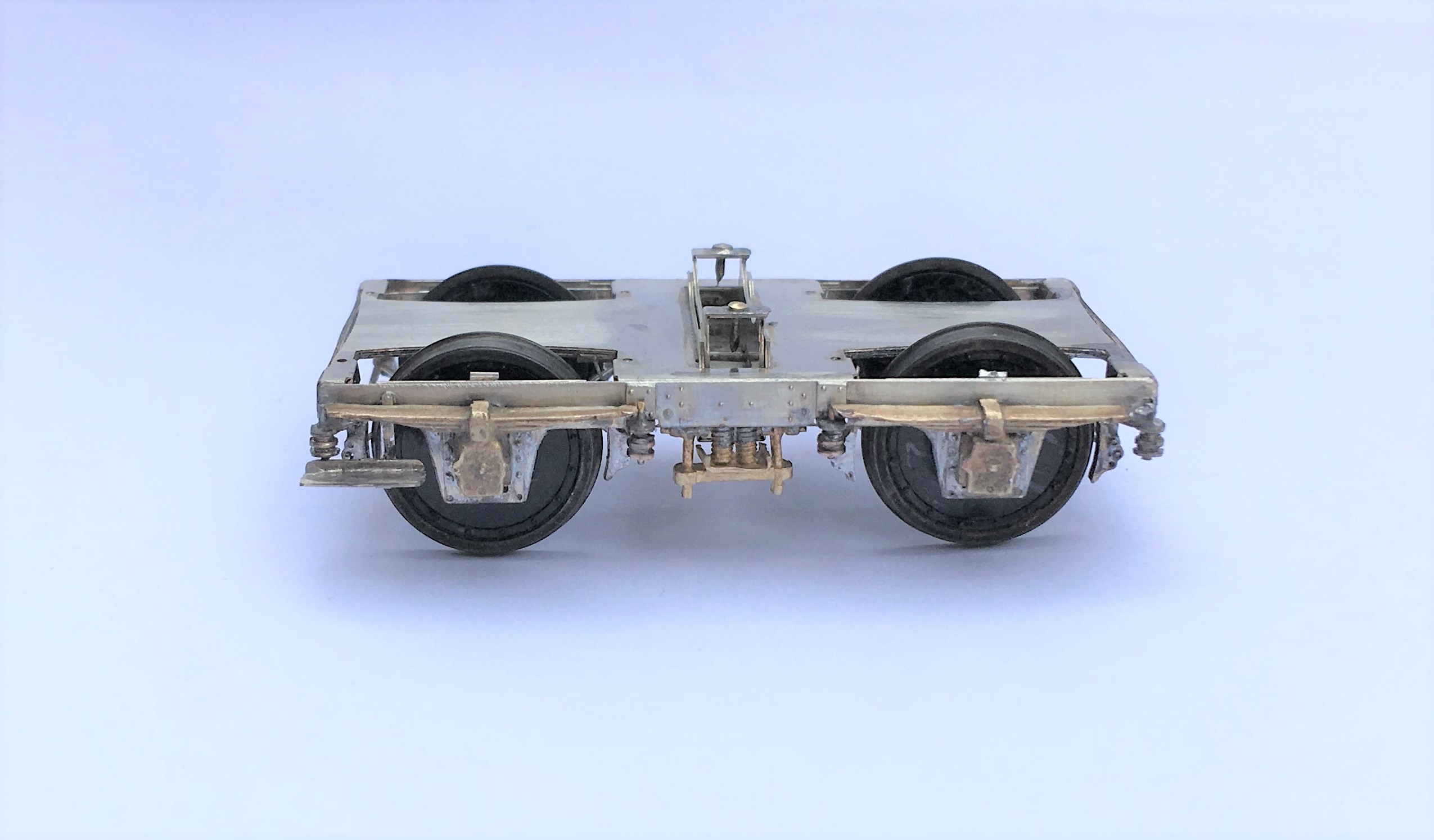
The etch is also designed to be provided with full stepboards as below or with only a short section to one end – as they typically were converted to during their life.
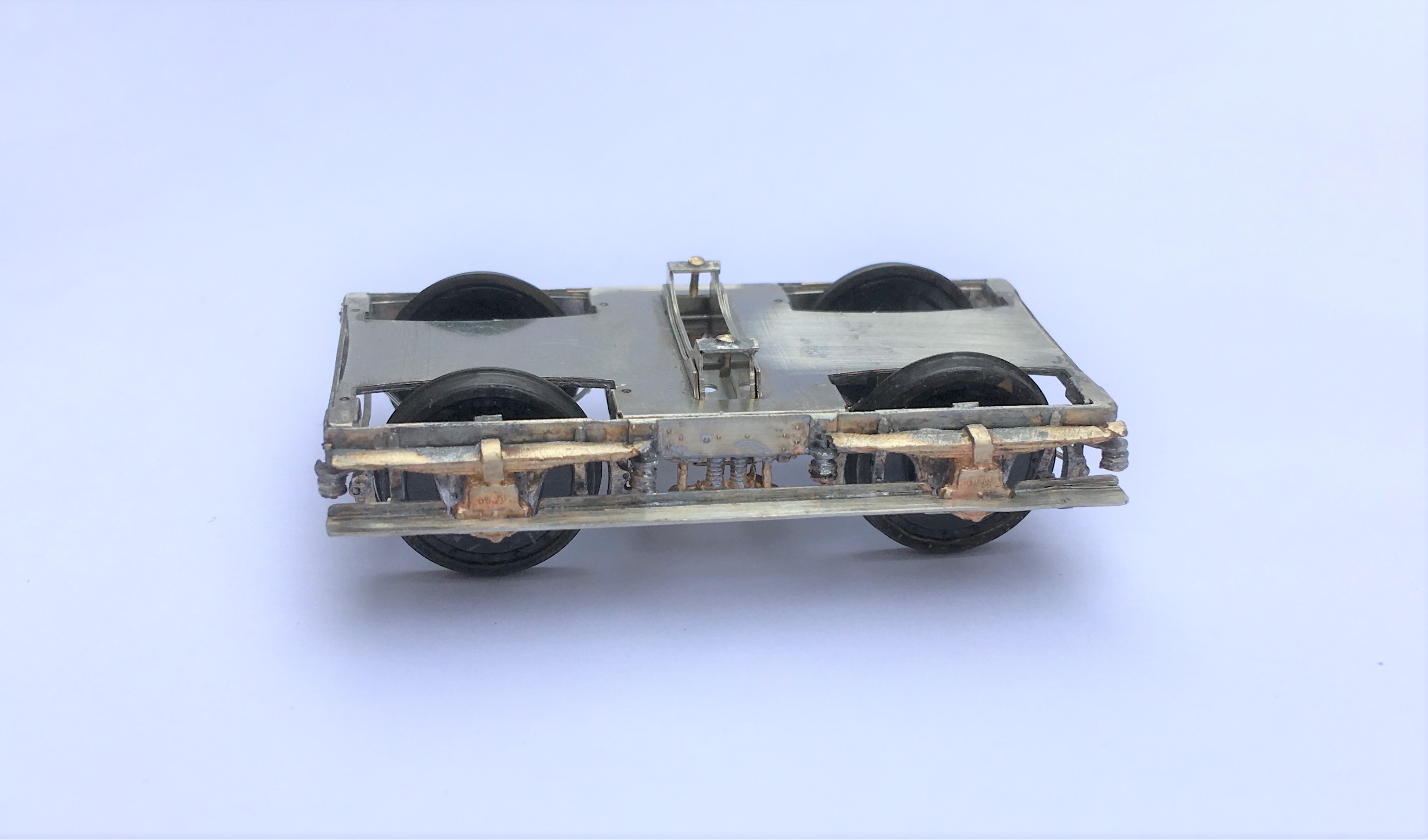
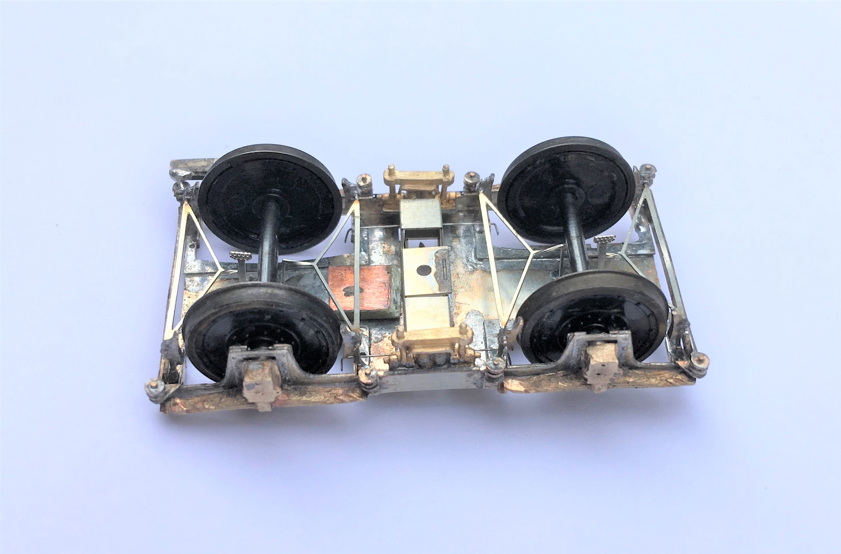
There is full brake gear provided, with a little trick where they do not pass under the axle (remember this view is upside down!) – this enables the wheel to be removed if this is required.
This is not the first version of these (don’t accuse me of not test building my designs!) and they are very close to done. The final change is to adjust the primary spring hangers slightly so that they are not visible when they are depressed (you can just see it poking above the sides in line with the axlebox), The advantage of computer drawn artwork is that things like this can be changed relatively easily.
These, and indeed the rest of the dia 51 full brake, will be made available for sale quite soon.
Previous parts to the test build can be found here:
- part 1 – the main body shell of the cupboard door version
- part 2 – the underframe
- part 3 – the second one, the sliding door version

Dia 51 Test Build Part 3 – and then there were two…..!
Following the first test build of the dia 51, I took account of what I had learnt from this and completed various amendments to the artwork. There was nothing truly major, so I was fairly confident that the corrections would get the model to the point where the artwork was done. But of course, to prove this, another test build was required and this is where we got to………..
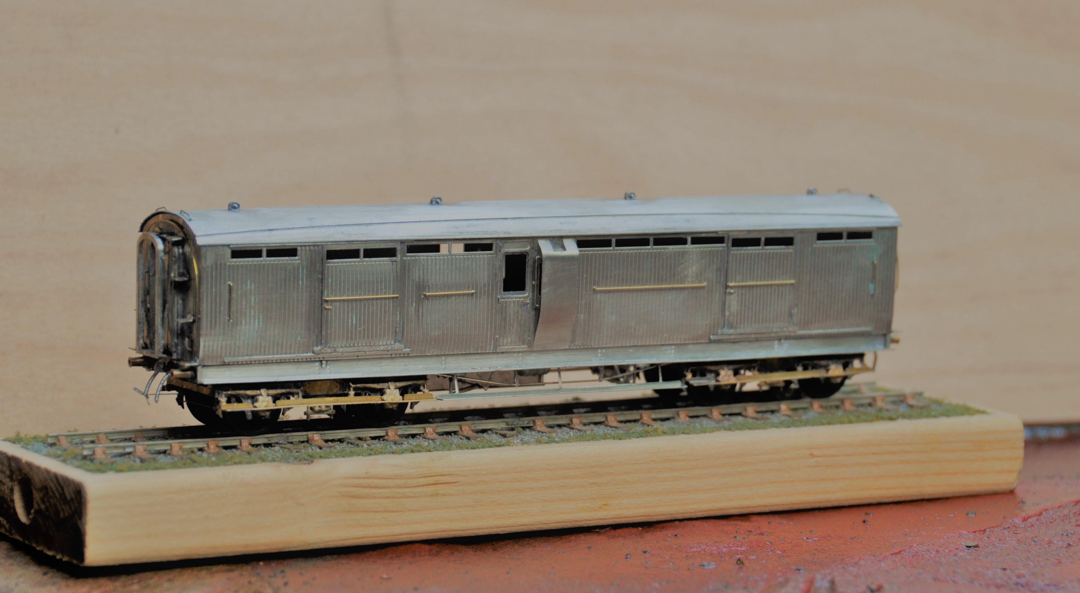
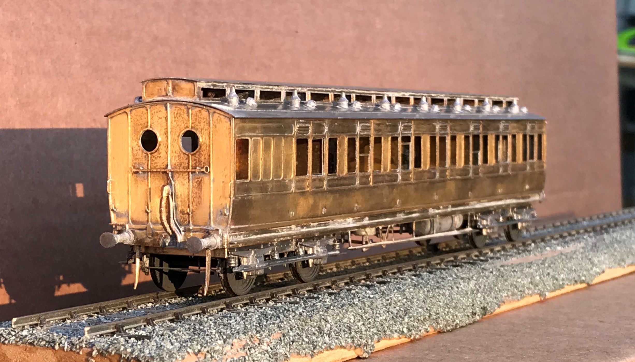
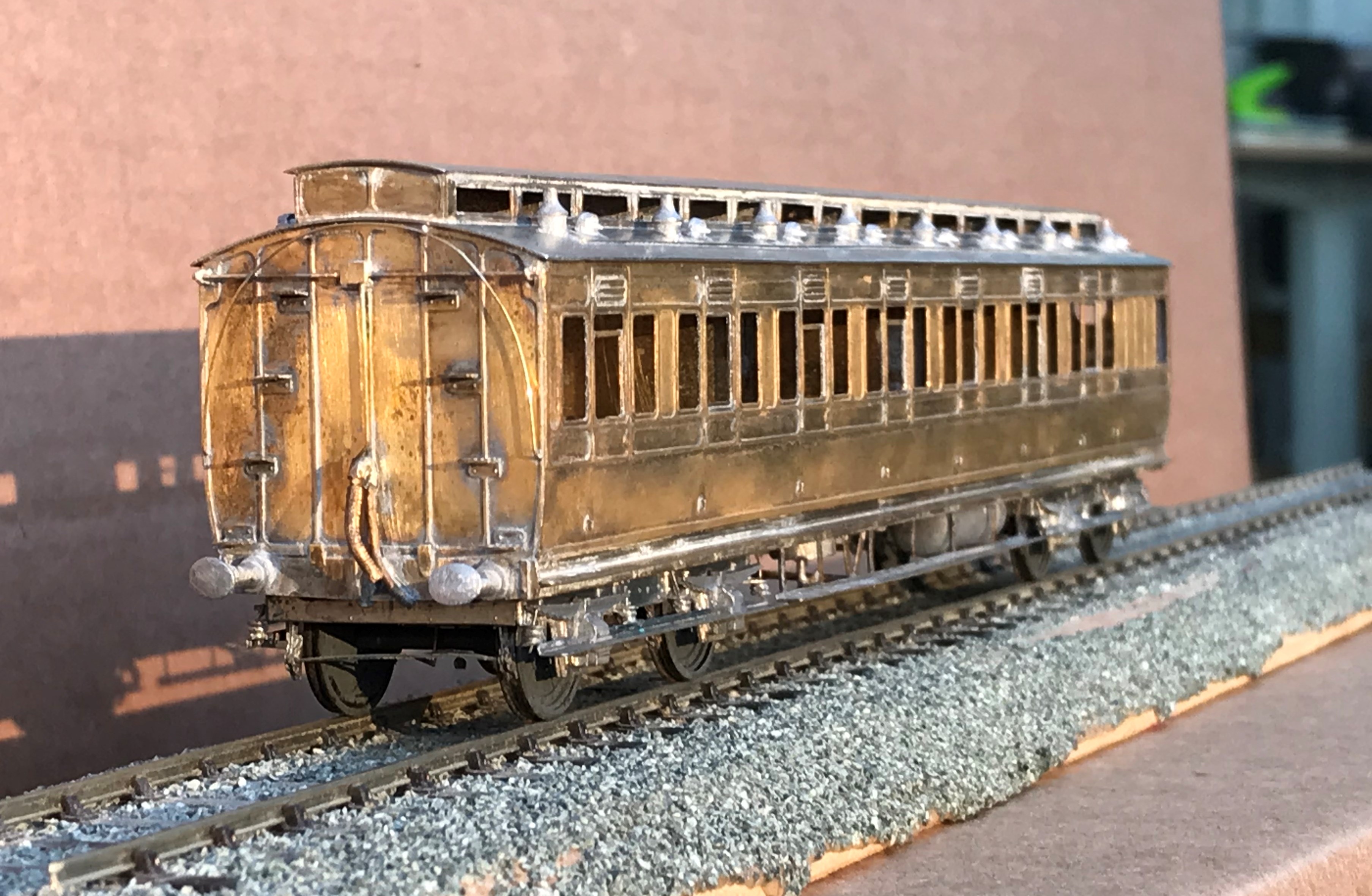
And this is what it looks like……..quite handsom I think and certainly quite differnt from all the pother stock I presently have.
The eagle eyed will spot that the vehicle is slightly different in that this one has sliding doors, whereas the previous had cupboard doors. The kit is intended to cover both options and does successfully do so.
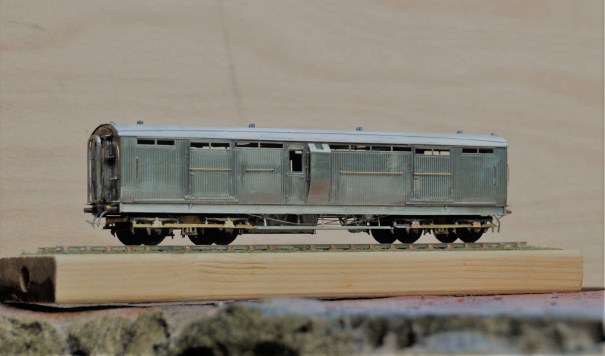
The ducket also has cut outs for a lamp at its head (a feature of Highland duckets). This proved quite challenging to model and I will avoid doing it again because it seemed to fall out of favour prior to the end of the Highland era so having only one or two would be right for my timeframe.
There remains a bit more work on the bogie to do; they can be made up to work very well but are a little more difficult to build than I had hoped. Once this is cracked, I will be making the dia 51 available for sale.
