Category Archives: Miscellany Models

News from Miscellany Models
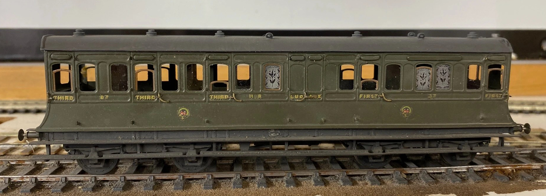
With the assistance of Duncan Petford, Miscellany Models are now offering engraved glass windows featuring the thistle emblem that the Highland used to obscure the windows of toilet compartments. They come in packs of five, for £7 postage included and are available here.
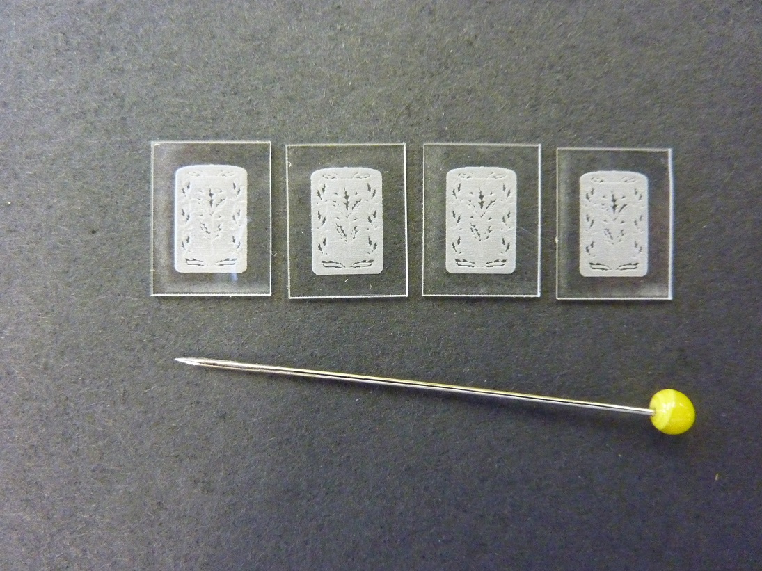
These are laser engraved on 1mm perspex and really lift the appearance of a Highland coach, as you can see:
Sadly, I have also had to increase the prices for most of the products. The costs of the last few deliveries from my etchers have been eyewateringly expensisve, so I need to defer a degree of this. The good news is that this is an indication that more products will soon be featured too – so Highland and LMS modellers keep an eye out.

News from Miscellany Models
Followers of this blog will have noted that various test builds of my artwork coming together and I am now able to offer a number of these for sale under the name of Miscellany Models.
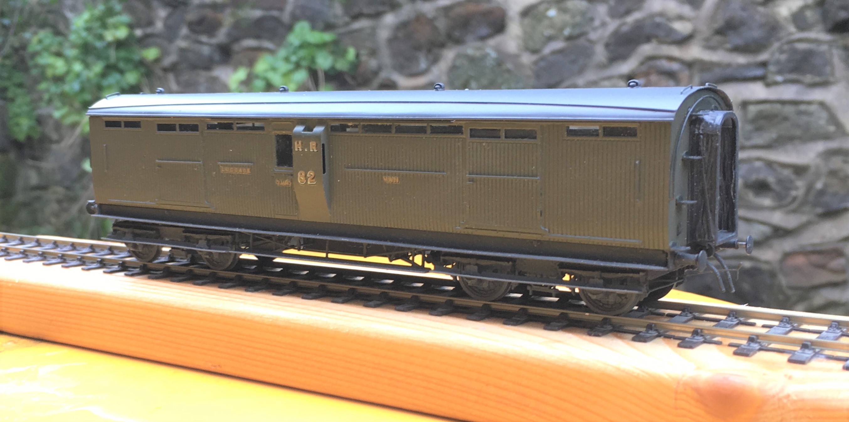
First up is a Highland Railway/LMS/BR diagram 51 full brake – priced at £48.00 for a 4mm and is suitable for OO, EM or P4. These were the last generation of full brake produced by the Highland, built with both cupboard doors and sliding doors as well as alternative forms of guards duckets (all of these are included in the kit). The kit inclusive of fully sprung Fox bogies (see below), roof, corridor connections (also see below) but all castings and buffers will need to be sourced separately. The castings for the bogies are proposed, but are not presently available.
As was common with many pre-grouping coaches these vehicles utilised Fox Bogies (£16.00) and these are being made separately to the remainder of the kit, These bogies have been developed in conjunction with Justin at Rumney Models and are fully sprung, with both the axleboxes and the bolsters sprung. They really do glide across track and look as if they weigh many tons rather than a few grams! They need castings for your favoured axleboxes/springs and bolsters but do include the foot steps and all of the bogies sides, brakes and details. Suitable for oo, EM and P4.
.JPG.3b26712c4490ad68695b10226612a0a9.JPG)
The second coach kit is for a MR/LMS/BR: Dia 530 Passenger Brake – priced at £36.00 in 4mm scale (suitable for OO, EM and P4). This prototype was built in some numbers and by the 1920s they were spread extensively across the LMS system. The kit is for full etches covering the roof, body, underframe and footboards plus parts for the sliding central axle included. It needs axlebox/springs (available from Branchlines or Coopercraft), gas lamps, buffers, brake and gas cylinders.
.JPG.1678157932a192d68328755d825c54f0.JPG)
On the wagon front, there is an etch to detail the NER/LNER/BR: Dia P7 Hopper Wagon – £13.50 4mm (sufficient for two wagons). They cater for a large number of the variants to this numerous and long lasting hopper wagon. Needs wheels and the Slaters kit P7 kit for the donor model. Variants that can be made include the end braked version, improved components for the Morton braked version, outside twin W irons and also the anti-friction wheel device.

All of these are available from my website https://miscellanymodels.com/ and in addition to this from the Rumney Models stand at the following shows – Scalefour North in April, Railex in May, Scalefourum in September and South Hants in November,
All of these have been extensively road tested by me with a couple of test builds for each of them. You can see this unfold on my blog and if you are interested in seeing how they go together do take a look!
Please remember that the availability of these models is an adjunct to my own hobby and this has to be accommodated within the constraints of my day job and general life! In particular I can’t get to post these orders until Saturdays so do please give me a little slack when it comes to getting the goods to you!
")
Christmas Layout Wiring (Not!)
I promised a number of people that I would be making sure that the layour had at least the main elements wired up over christmas, so that it could at last run. But then it was a bit wet and cold so I did not fancy it out in the summerhouse so I applied rule no 1 – its my trainset!
Instead, I stayed at the bench and made a pair of the signals that still remain to be made for Glenmutchkin. The signalling plan has developed very slightly since I originally showed it back here and is shown below (actually this is the artwork for the control panel facia).
The signals that I built were those that control the main loop prior to the shed link – levelrs 27 & 28 – and then the outer starter (that covers both the main loop and the main line) – levers 23, 24, 25 & 26. Only a pair of two doll signals, I thought, they shouldn’t take more than a day or two? Phew, well that wasn’t right; the more you look at the prototypes, the more you find there is to model!
Having created much of my own etchings and castings for MacKenzie & Holland signals I have obviously made good use of these. In this case, the small brackets, arms, ladders and castings.
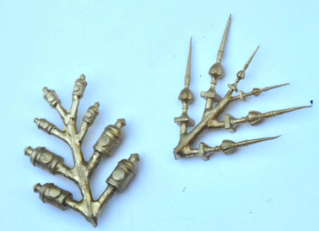
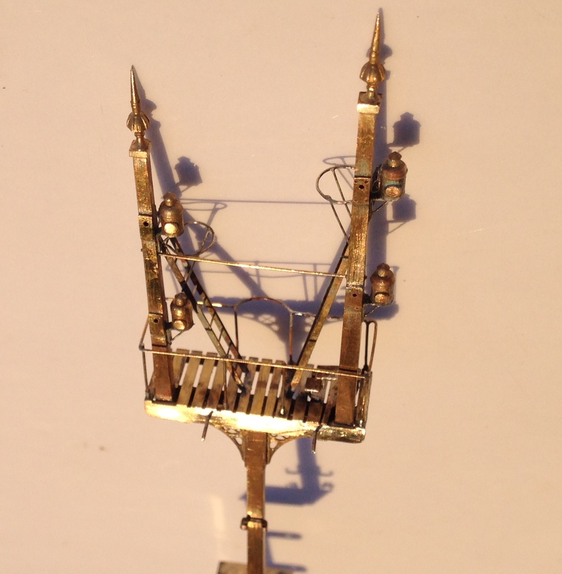
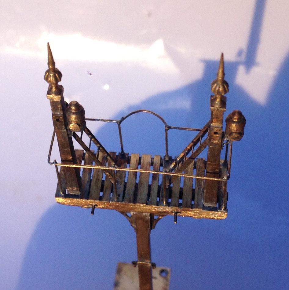
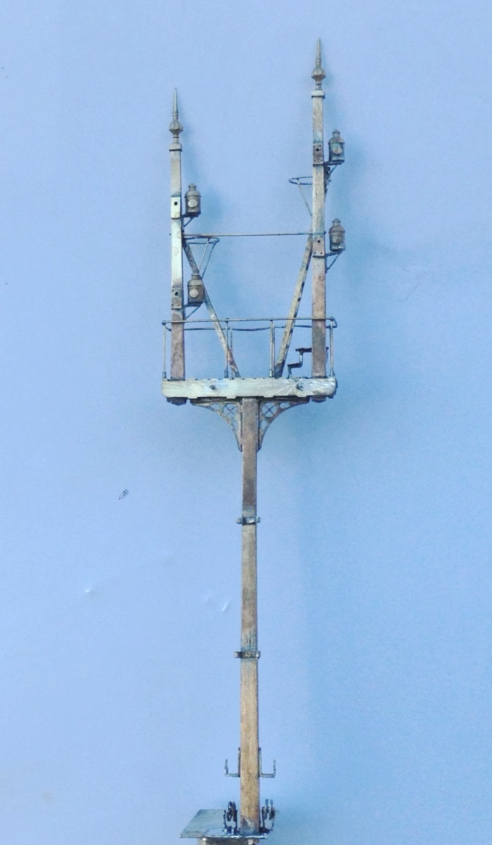
Both of the signals have used the small brackets to create smallish landings. The smaller of the two signals has only one arm per doll, the larger two. The dolls and the posts are made up of square brass section which is filed to a taper – a certain amount of elbow grease is needed to acheive this! The posts are then sandwiched between some transom beams that also clasp the doll post – this is all soldered with a high melt solder to stop it ungumming later.

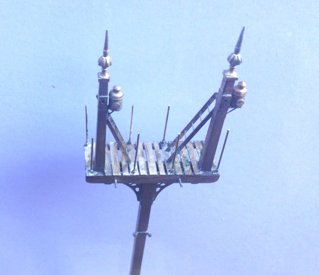
The brackets are then offered up from below, with scrap etch forming the bearing plates to pick up the transomes. In the etch I also included smaller brackets to pick up the free end of the landing, along with the landing itself. This gets you to the stage shown above.
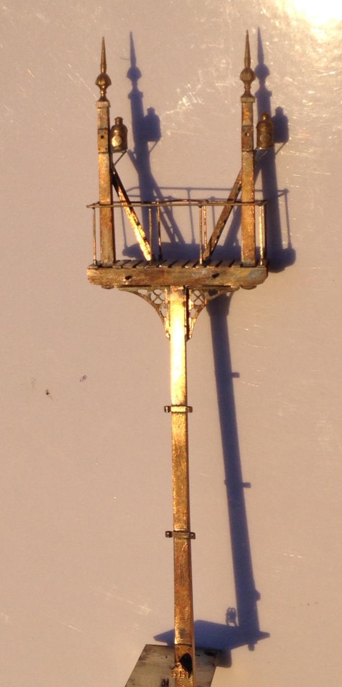
But this is not the half of it on a signal, there are the finials, lamp brackets, lamps, cross stays, access steps, access ladders, pivot plates, handrails, operating cams, safety hoops and ladder still to do………..
 .
.
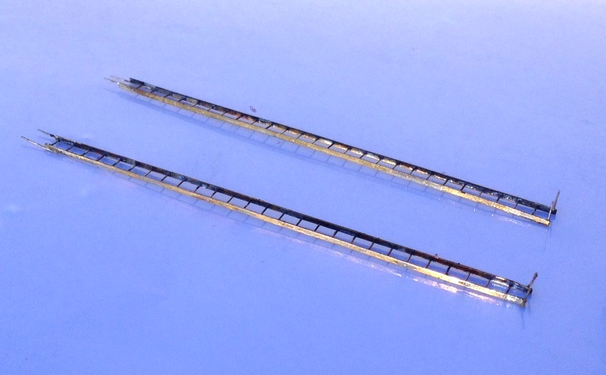
In a departure from my previous practise, I made the main ladders detachable (they will be held with the wire that can be seen in the pictures being turned over in secret pockets. I am also going to paint this prior to the final assembly; which will mean some touching uo of the painting later but I hope will make it easier.
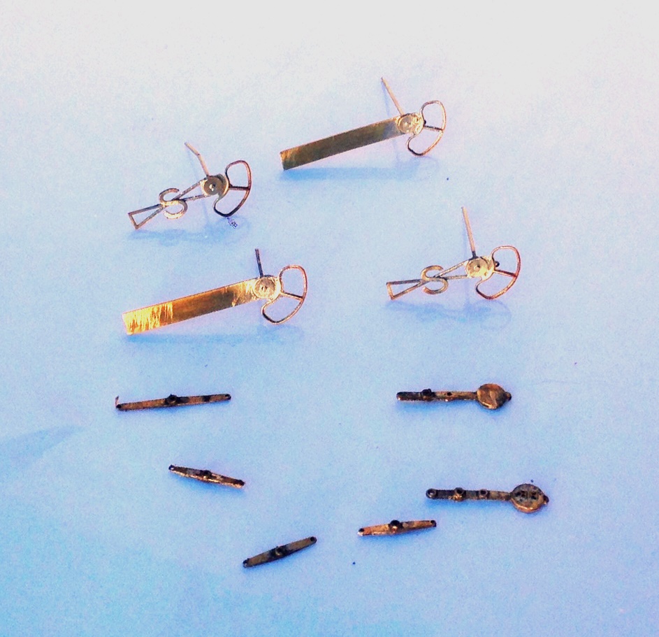
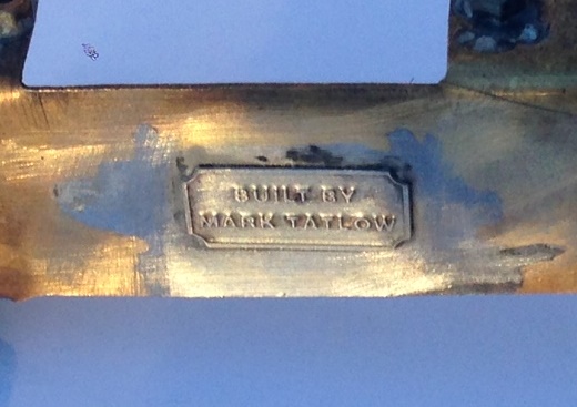
And of course, I had to sign them with these rather nice custom name plaques from NBR 4mm Developments.
This is the first time that I have used the brackets in signal making and I was pretty chuffed with how they have come out. This is where things presently stand and we head for the paint shops tomorrow…….

Going Long…….Part 1; the Underframe.
In comparison to the coaches that I use on Portchullin, most coaches from the 1920s (my chosen period for Glenmutchkin) are shorter and in many cases, even without considering the six wheeled vehicles, a lot shorter. This was driven by the technology and in particular the materials available to the railways of the time. There were exceptions though, and my present build is dealing with one of these – an East Coast Joint Stock 12 wheeler.
In the early 1890’s, the journey north was all about speed and culminated in the Railway Races to the North where the rival east and west coast companies competed to get their services to Aberdeen first. This came to an abrupt end in July 1896 when a west coast train took curves too fast at Preston and left the rails. Although the loss of life was relatively limited (for the time), excessive speed as a result of the desire to “speed to the north” was firmly blamed. As a result, the competing companies agreed no longer to race each other and instead sought to compete on the basis of the quality of their service and the luxury of their trains.
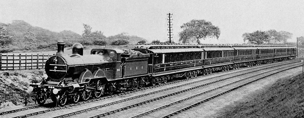
A GNR small altlantic hauling an ECJS express at the turn of the 19th Century made up predominantly of 12 wheeled stock
One product of this competition were some really fine 12 wheel coaches built for the East Cost Joint Stock Company (which was a joint company with the GNR, NER & NB contributing to the cost for trans-company trains). Built from 1896 onwards, these were several different lengths (this particular example was 66’11″) but all were long, seeking to use length and mass to iron out any track irregularity. To support this length of coach, six wheeled bogies were used, although these were rather infant in their design and used big transverse leaf springs as bolsters. In addition to being really characteristic and obvious – so they need to be modelled – I suspect they gave a somewhat bouncy ride!
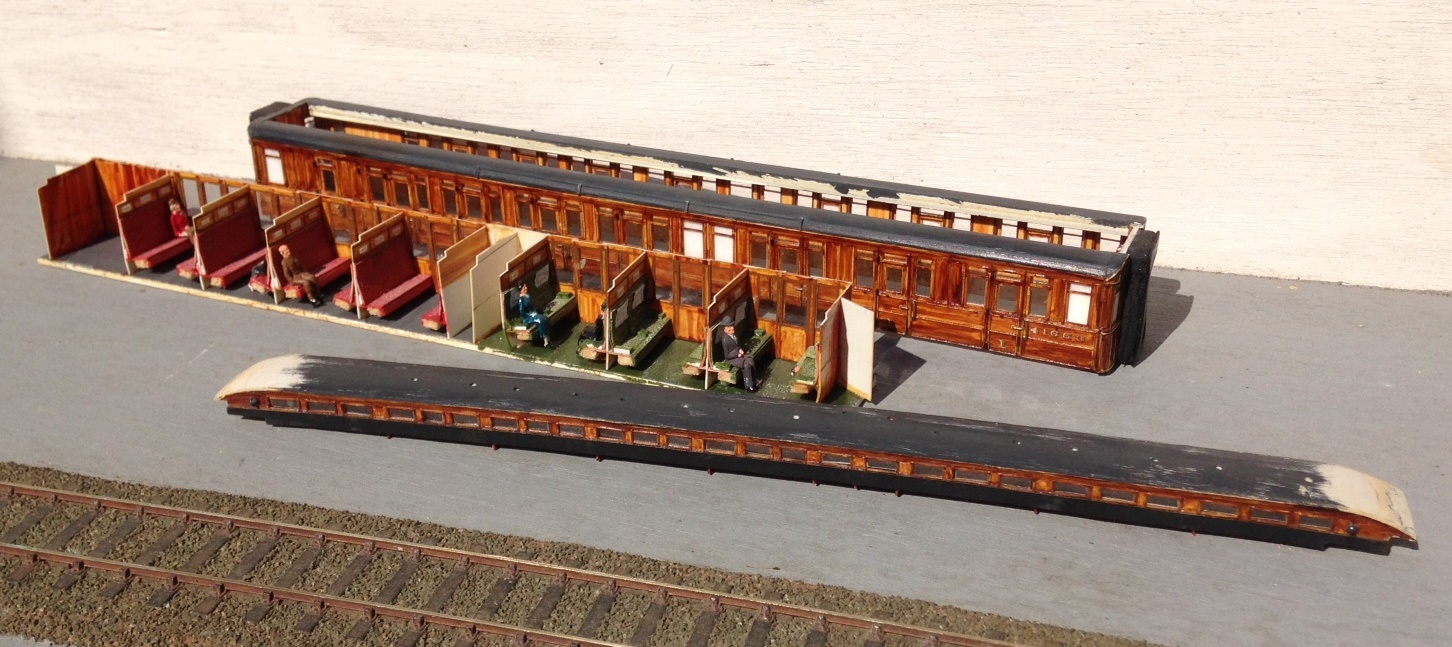
Barry Fleming’s scratchbuilt body and part completed roof
I have been given a big headstart on this build by virtue of being given a nearly complete body/roof for a luggage composite (diagram 6 for those in the know). This was scratchbuilt by the late Barry Fleming in the 1980s and is a class bit of modelling! Barry gave it to my father, along with a couple of other coaches, to complete but as he has not managed to get this particular one, he has passed it to me to have a bash!
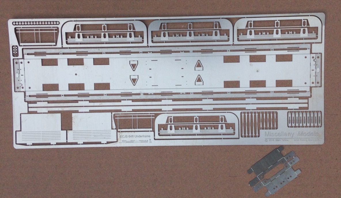
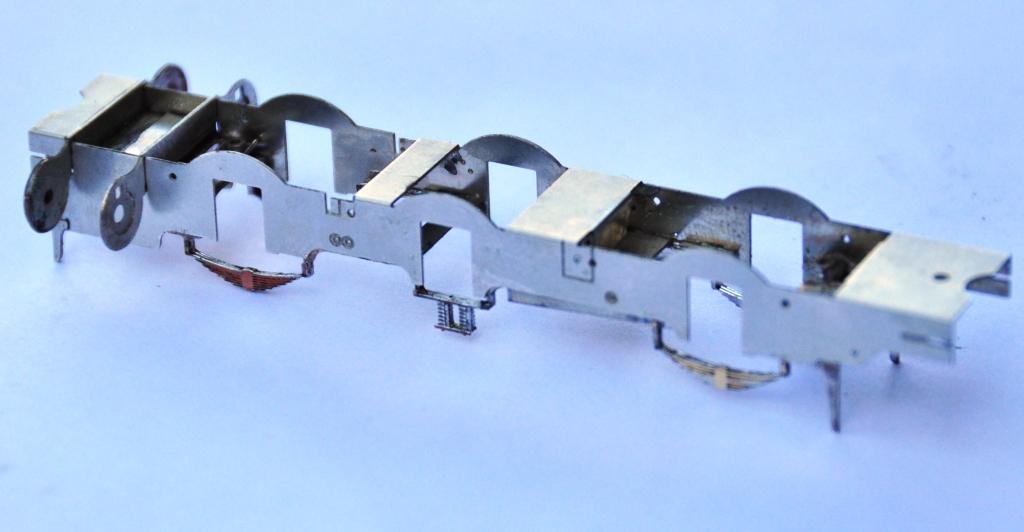
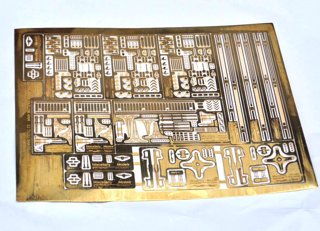
My etchings back from PPD
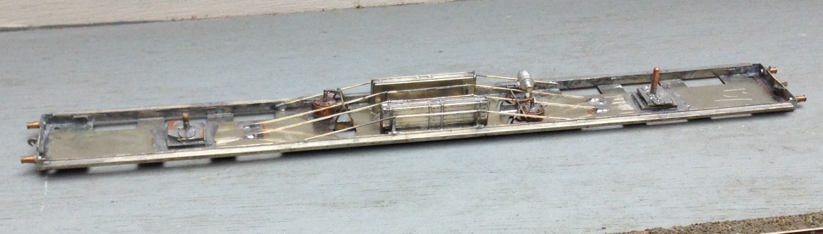
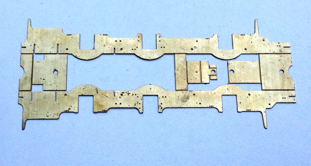
One of the reasons that this model was put to the back of the queue previously was that almost none of the parts required to complete it – in particular the bogies – were available, so it was all going to be a scratchbuild. As I was pouring over the drawings and pictures in the bible on things ECJS it dawned on me that the missing parts would be best dealt with as an etch and given my developing skills in etch designing, I might was well have a go. This is the product, an underframe, some cosmetic bogie sidesand some underframe details fresh back from the etchers.
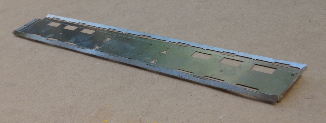
The basic underframe has fold up solebars and buffer beams. Each of these also has integral fold over layers to laminate on the cosmetic exterior. This just about worked for the solbars but definitely did not for the buffer beams which distorted due to their thinness. I will make these seperate pieces next time, but might use folding jigs.
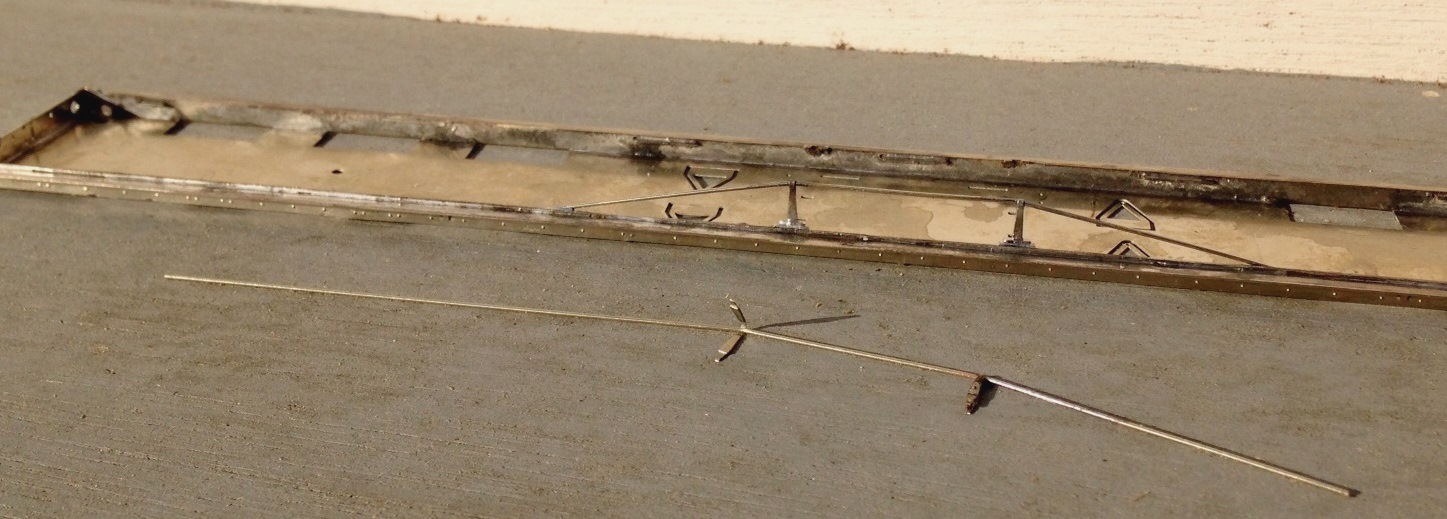
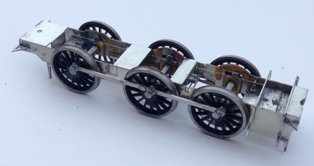
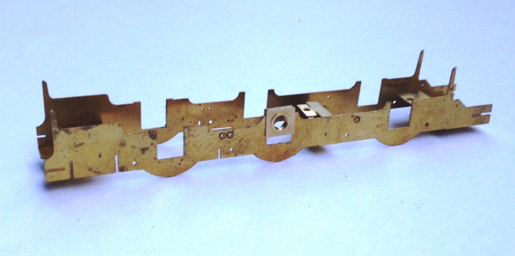
Coaches of this era tended to have four truss rods, each with a pair of queen posts. Stealing an idea from Alistair Wright’s designs, I made the queen posts up by a long etch that has a half etch length to wrap around the wire used for the tie rod. By folding this over the wire and then laminating the two parts together, a robust and simple post can be created. As it is two layers soldered together, it has the strength to allow it to be filed to a round shape to create the appearance of the original.
Although originally gas lit, by the time I will be modelling this vehicle it was electrically lit. Whilst I probably could have bought cast batter boxes, I decided to include them in the etch and very pleased I am too – they have come out much more crisp than any of the castings I have seen and were really easy to both draw and make. The remainder of the fittings seen here were bought in castings though, typically from Comet Models (now distributed by Wizard Models).
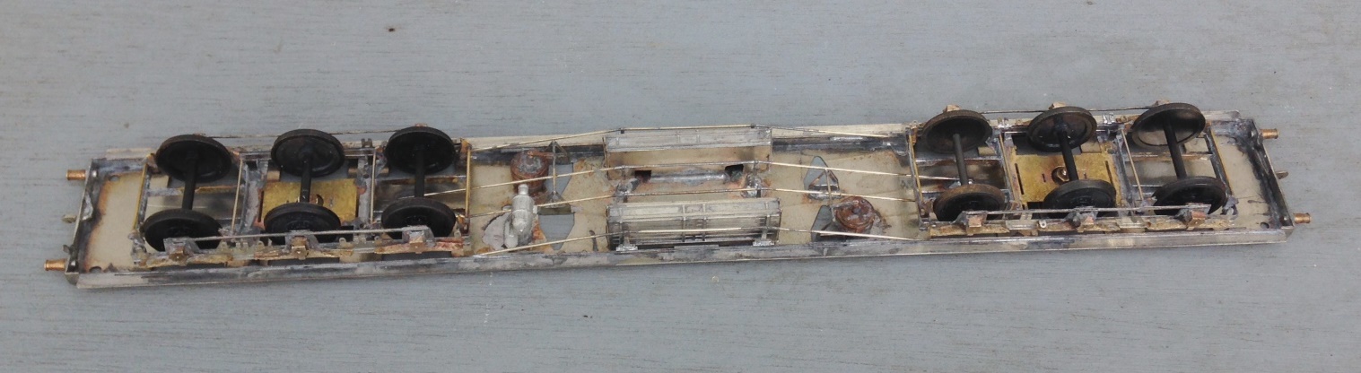
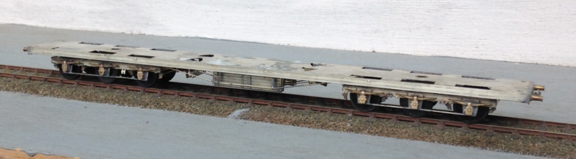
And this is where the underframe has presently progressed to.
I will describe the building of the bogies in the next installment, they are not for the faint-hearted!
Transfer Update
Back in November 2013, I hinted that I was trying to crack transfers for the Highland’s locos in LMS days; something that is not realistically available via other sources and there does not seem to be much prospect of anyone else doing them.
Anyway, hopefully, I have cracked all I need to with regard to these and the final artwork is complete. This is what it looks like – hopefully it has covered all the locos you might fancy!
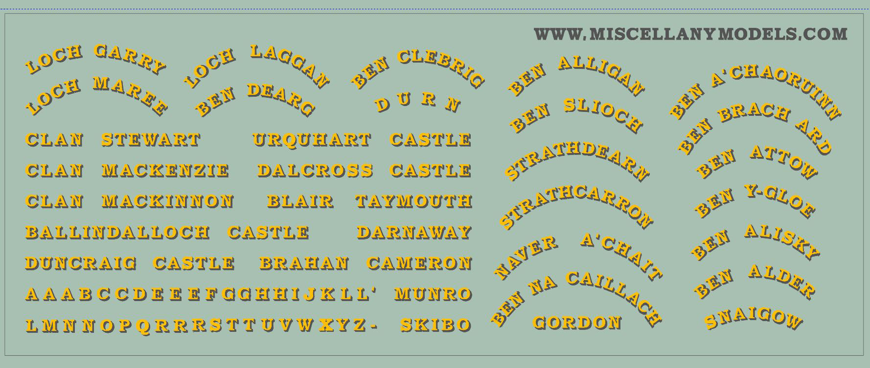
Also on the sheet are one or two other things; but I am less certain that these will work so I’ll keep these as a secret until I find out.
The intention is that these will be available in 4mm & 7mm scales; pricing to be confirmed but I am afraid they will be fairly expensive as the production run is not big and you 7mm chaps in particular eat the page with the size of the prints!
Once they come in, I decide whether they are viable.
Scrap Tank Test Build 8 – Casting Masters
The update on the Scrap Tank test build shows it looking like this:
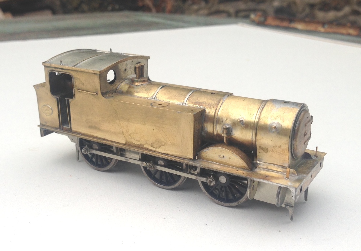
The eagle eyed, and indeed the slightly less than eagle eyed, amongst you will notice that this is not a whole lot different to the last update, just a few fittings have been installed – basically the ones I could glean off other things; the safety valves/bonnet and smoke box from Lochgorm Models and the clack valves from Alan Gibson (but much cut down as they are really much too big). I have not been able to fit any other castings because they don’t exist, so I have had to do some more work on these.
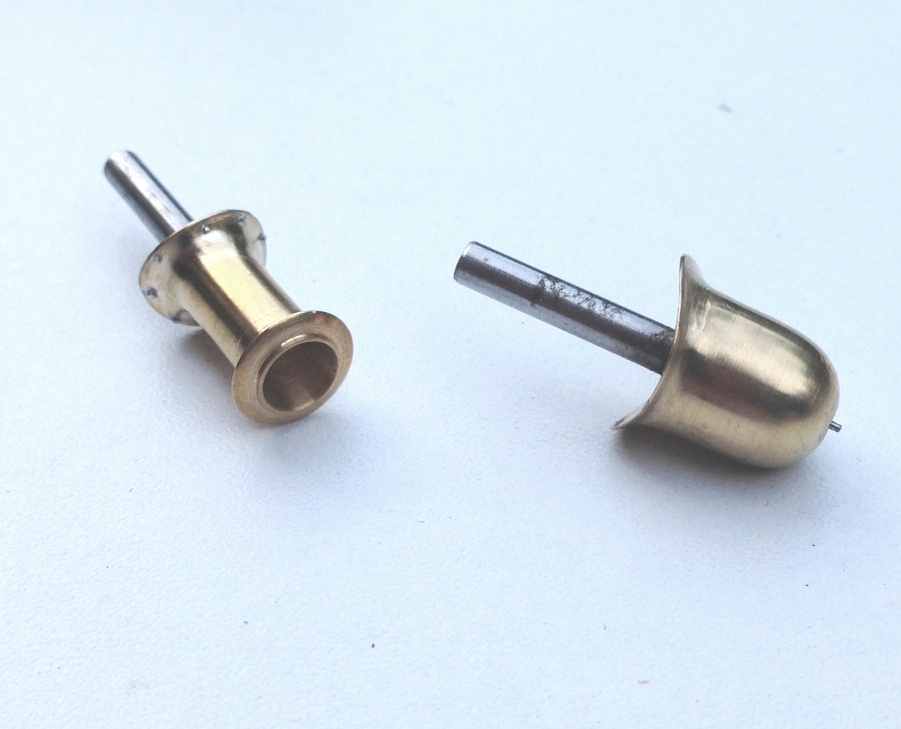
So it is back to the CAD machine to draw up a series of 3D masters; in the top view some piston rods/part of the cross head, rear sand boxes, clack valves (now the right size which is much much smaller) and some lubricator valves. The bottom view has some tank filler lids, front sandboxes and piston ends.
These have been printed for me by Alan Butler of Modulu who is a new entrant in the field of 3D printing and has a system/machine that can do really small parts very well indeed; definitely better than Shapeways. Alan is a railway modeller here and blogs here – well worth a look I suggest and if you are thinking of having some things printed then I would get in touch with him.
I did not get Alan to print the dome and the chimney, partly because I had my doubts that the print would do the fine lip of the metal where it meets the boiler but mostly because I just could not work out how to draw the damn thing! Instead, therefore I commission Jeremy Suter to make these for me:
……..and very fine the look too!
So, these are the masters all sorted and they will shortly be sent of for casting. I will be using lost wax again, as I much prefer this to white metal; although I do accept that the better white metal casters do do a grand job.

Scrap Tank Test Build – Part 7; Boiler Assembly and Finishing the Cab
Next up is the finishing of the detailing of the cab. Common with many tank engines there were grilles over the rear windows. For these, I toyed with the idea of doing these as a single etch, a bit like the Mainly Trains one (and possibly others) but elected instead that the slight roundness of the bars needed to be captured, so this meant that brass rods were going to be required. If I had either etched small holes or soldered these on top of the cab etch, I felt that getting consistency of spacing was unlikely and that this would detract from the finished effect. Thus, it was time for a little jig.
This jig is simply a sheet of brass with holes for the wire at the appropriate spacings along with half etched lines arranged such that when the jig is folded over, the wire is trapped between them. This is what it looks like with the wire in and the jig folded over (along with a dab of solder to hold it all still):
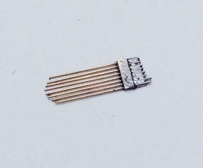
You will note that in the picture above, I have trimmed the wire rods to a gentle curve to reflect the curve of the spectacle plate and in the picture below, this has been soldered on the ring around the window. The jig is then snipped off and the rods can be cut away. I found that by using a scalpel, it was possible to cut a nick in the rods and then the wire could be carefully lifts so that it snapped at the point of the nick. It was necessary to ensure that the rods were soldered well to the sides as if this joint failed it was then pretty difficult to get them soldered back down neatly; I will include a space jig in the production etch of the kit to give the user a second chance!
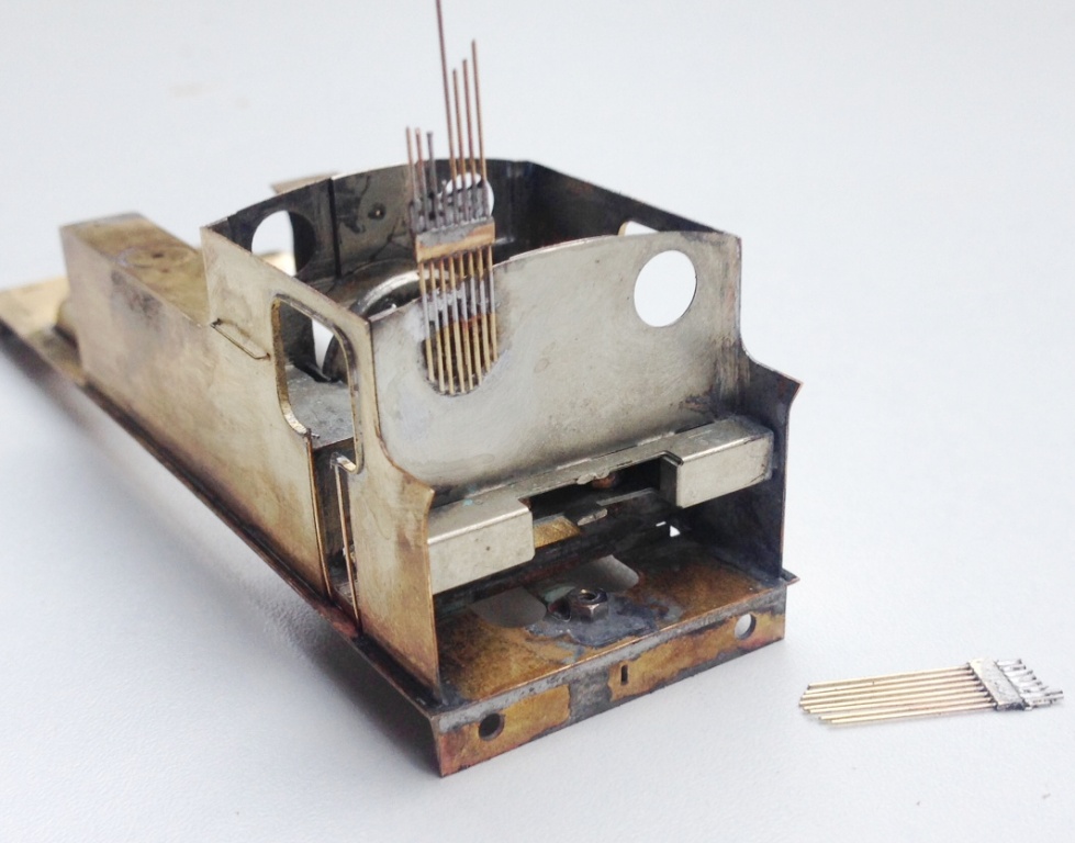
There is also a beading around the cab side openings, a common feature on pre-grouping locomotives. This was relatively simple to fit, although I did make it a tad too fat deliberately to assist in the process – it can then be filled back to a thinner dimension and in the process any slight irregularities taken away in the filing. In this example the stanchions are probably a bit far away from the cab sheets, so there will be a slight adjustment on the final version.
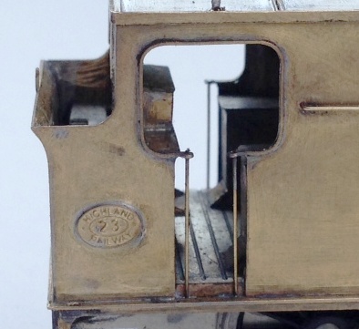
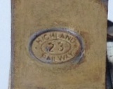
Also worthy of note is the cabside number plate, which I am dead chuffed with. This is a cruel enlargement as the whole plate is only 6mm across and to clearly be able to read the text which is only 0.7mm high is pretty good I reckon!
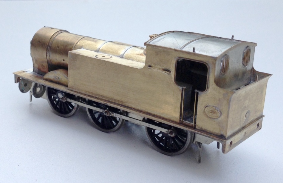
After finishing the cab detailing, it was time to add the boiler onto the tanks/running plate and she is beginning to look like the real thing, although perhaps looking a little naked due to the missing dome and chimney at present!
I have fitted a safety valve bonnet and safety valves from those intended for the Strath/Loch and available from Lochgorm Models. I also formed the front splashers, which I had tried to make easier by the use of some tabs and formers. These did assist in the assembly but I then found that they fouled with the wheels, as I had made the splashers true to scale and the tolerances did not allow for the tabs. I will have another think here and might come up with a jig, as splashers are sometimes a bit painful to fit.
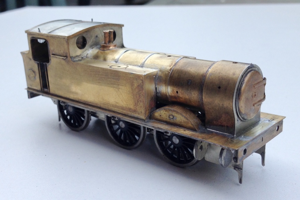
And this is what she presently looks like; definitely beginning to look like the real thing (a reminder of which is below). For those of you that are coming to Scalefour North I will bring her along for you to have a look at. As we are now about up to date with her construction (you didn’t think I can build that quickly did you?!?!) and because I am away the whole of this weekend at Scalefour North, there will be a hiatus a bit before the next posting.
Scrap Tank Test Build – Part 6; Boiler and Running Plate
Now that the much of the bulk of the above running plate work has been completed, the running plate valences can be fitted. As these are nearly always long and thin, they are prone to distortion in the kits I have built – so it is time for another jig!! This one holds the valences at numerous places to stop it flexing and to hold it straight.
With this, it is a doddle to fit the valences in their correct place and solder them without distortion. I did find that the running plate flexed significantly at the end of the tanks; so the final version is going to include a pair of temporary stiffeners that fold down and stop this. This would be the moment when they are removed to allow the valancing to take their place.
And onto the boiler. In a departure from normal practise, I am not including a flat etch to be rolled into a boiler – it is relatively difficult to get even a pre-rolled boiler into a neat tube without a visible seam and if you do not have a rolling machine it is effectively impossible to do so. In addition, where boilers have been half etched to create boiler bands I find that the half etched elements that remain are overly delicate. This was something that caught me out a while back when I drilled such and area to take handrail knobs and badly distorted the metal – this kit is still sitting in its box now and I am probably going to have to replace the boiler.
With these problems in mind, I simply used a piece of brass tube from Eileens; easier and much more durable and if I were sratch-building I would not even think of taking a different route. This did still leave the need for some rolled parts, to make the smokebox and I have sought to use another little trick here to make these easier to fit – some tags and eyes. The tags are strips of half etching that pass through the eyes and then tugged back. This can’t impart a curve into the metal but does allow the parts to be pulled tight and makes it easier to solder into place without much of lip. Mind you, they were a tad short and will be lengthened slightly in the production run.
A second additional laminate is then needed to form the outside of the smokebox and down onto the saddle.
I did find another little error when it came to the front of the smokebox. Whilst the diameter for the front that I had drawn had allowed for the thickness of the two laminates, when you fit these there is also a layer of solder between them and whilst this ought not be that thick, it was just enough to make the fronts too small. In the production run, I will deliberately make this a tad too big as it is easy enough to file it back but much more difficult to add the missing metal (I didn’t, I just made a fresh one from sheet metal). The smokebox door is not mine, the door from the Lochgorm Models Loch is the right size judging by the photographs (note the drawing in the old man’s book has it being smaller but this does not match the photos, so I ignored it in this respect – sorry Dad!).
The downside of using tube as a boiler is that boiler bands need to be considered. I have provided these in the kit (again using the strap and eye technique). I chose to fit them on this kit although in practise I think any metal boiler band is too thick and would probably have done it with a transfer sheet if this was not a test build (done prior to painting, the thickness of the transfer is enough to show through the paint on what will be a single colour to the boiler).
Only the top of the boiler is visible after the first ring and a bit, so can be cut away to leave lots of room for the motor, weighting and DCC chip. I may try and fit this with sound, so who can give a view on what it might have sounded like – a jinty is my favoured guess?

Scrap Tank Test Build 5 – Getting on with the Chassis
With the basic chassis made, it is essential to fit the nuts to secure the body to the chassis as both of these will be concealed with later work. So a quick test fit looks like this and we can get onto the next bit, the coupling rods. 
As is not uncommon, these are made from a pair of layers of brass laminated together. You can see that the outer layer is half etched for much of its length, with the full depth only being present at the bosses. I have also sought to make it easier to build these by including them in a folding jig – the folding is underway in the bottom portion of the view. The logic of the jig, indeed the whole kit, is to make a really smoothly running chassis much easier to make. Modern CAD and computer operated phototool creation techniques by the etchers means that it is possible to easily draw and then etch such that each dimension is faithfully repeated on the product. Thus, it is possible to be confident that the wheelbase will be repeated exactly on each side of the frames and also on the coupling rods. However, this accuracy is completely lost if the user has to laminate the two parts together by hand; it is not possible to get them superimposed on each other exactly or repetitively so the spacings of the crankpin holes will change. The jig overcomes this as the fold line is so long that there can not be any twist as it folds, so the two parts will meet consistently and accurately. 
It is true that there remain two areas of variability. The first is that the degree of etching will not be exact on every occasion so the holes will be slightly bigger or smaller on each occasion. This can be easily overcome by making all critical holes a tiny bit too small and then opening the holes up with a ream (not a file, reams will open up a hole consistently). The second problem is that a fold is not always consistent on a fold line so the jig can protect against twisting but might not necessarily put the two laminates directly on top of each other. However, the important point is is that they will be correct horizontally, any error can only crop up vertically. Thus, when the crankpin whole is opened up, it is possible that it will move vertically slightly but this will not change the dimension between the holes so the critical dimensions should be retained perfectly.
The above is all true in theory but in practise there was an almighty cock up in my artwork; so I was deprived of finding out. A total case of designer error and when this is yourself, there is no one else to blame………………. 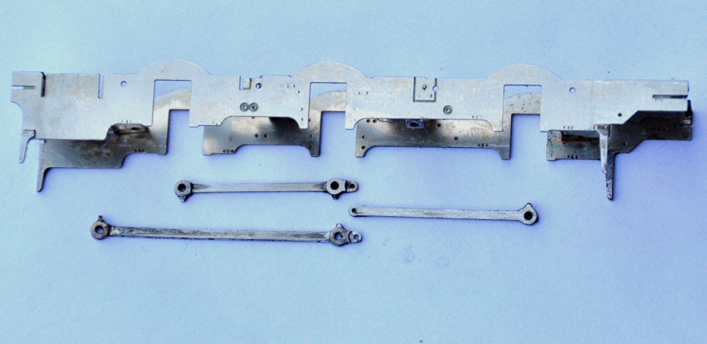
………..I made one of the coupling rods no less than 8mm too long – doh! I have no idea how, but it needed chopping; so it was back to the old fashioned way of making coupling rods despite my high ideals! Fortunately, as they were laminated, it is possible to stagger the cut to make the splice – essentially the same technique as Alan Gibson’s variable length coupling rods. Anyway, after the cutting and splicing, I did get a sweetly running chassis and this is what it looks like. The unusually large wheels for a shunting loco are already making their presence felt! 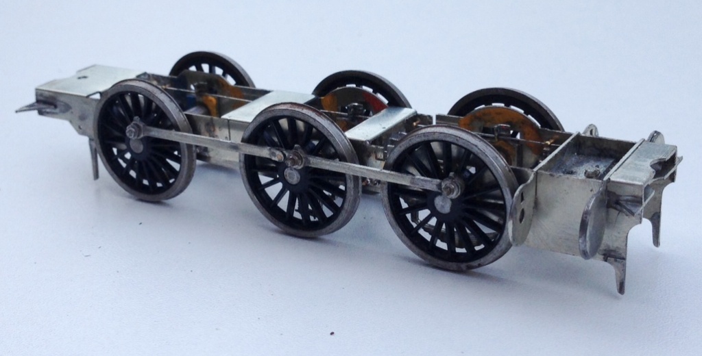
The chassis is created around CSB’s; continuous springy beams. A spring wire is anchored to the chassis at four points per side (for an 0-6-0) and at the centre of each hornblock. Thus each hornblock is supported on either side and can “bounce” on the spring. However, the clever thing about CSBs is that when a hornblock is depressed, not only does the spring wire flex a bit as suspension, but it also rocks on the anchors so the adjacent wheels push downwards a bit to equalise out some of the deflection. It produces a really smooth chassis and, if it is conceived at the design stage, I think is actually rather easier to both design and build than traditional compensation. This is a close up of a pair of hornblocks and a pair of the anchor points (the other is hiding behind the frame spacer on the right). Also worthy of note is the colour coding of the hornblocks; to enable them to be reinstated in the same hornguide each time. This is probably unnecessary with modern (and therefore consistent) hornblocks and the accuracy of the etching I have noted but old habits die hard! 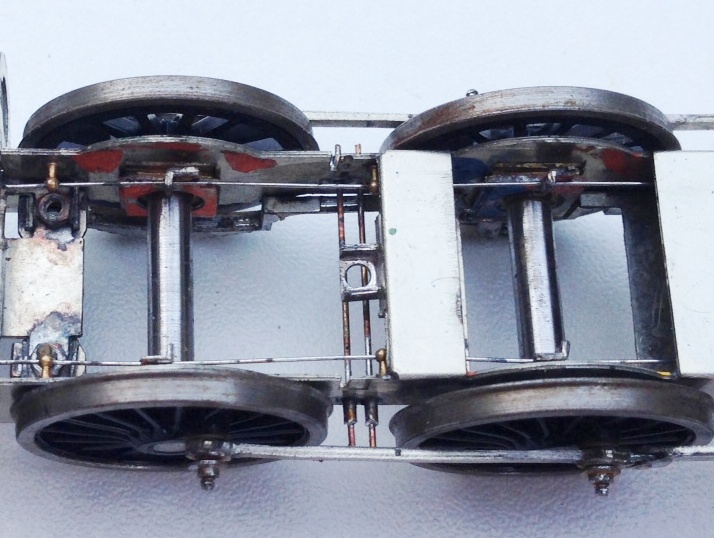

Scrap Tank Test Build – Part 4; Beginning the Chassis
Putting aside the body for a while, to take a look at the chassis because it is necessary to mount the two together and it is not possible to close up some of the element of the body until this is sorted out.
As with the body, I am trying to take a moderately fresh approach to the chassis to make this a little easier to build than certainly most of the kits I am used to. In this regard, most of the kits for the Highland are quite traditional in their design and I readily admit that all but two of my ideas has been either all out pinched from other designers or at least significantly inspired by them. All I am trying to do is use more of these neat ideas in a single kit to make the life of the builder easier. I am, however, finding that it makes my life more difficult, as there are a lot more moving parts to most components, so more places for the tolerances to be catered for; so as John Price has already said, the list of little tweeks and amendments to make is growing! At least, no one can say this particular kit designer has not built their own model.
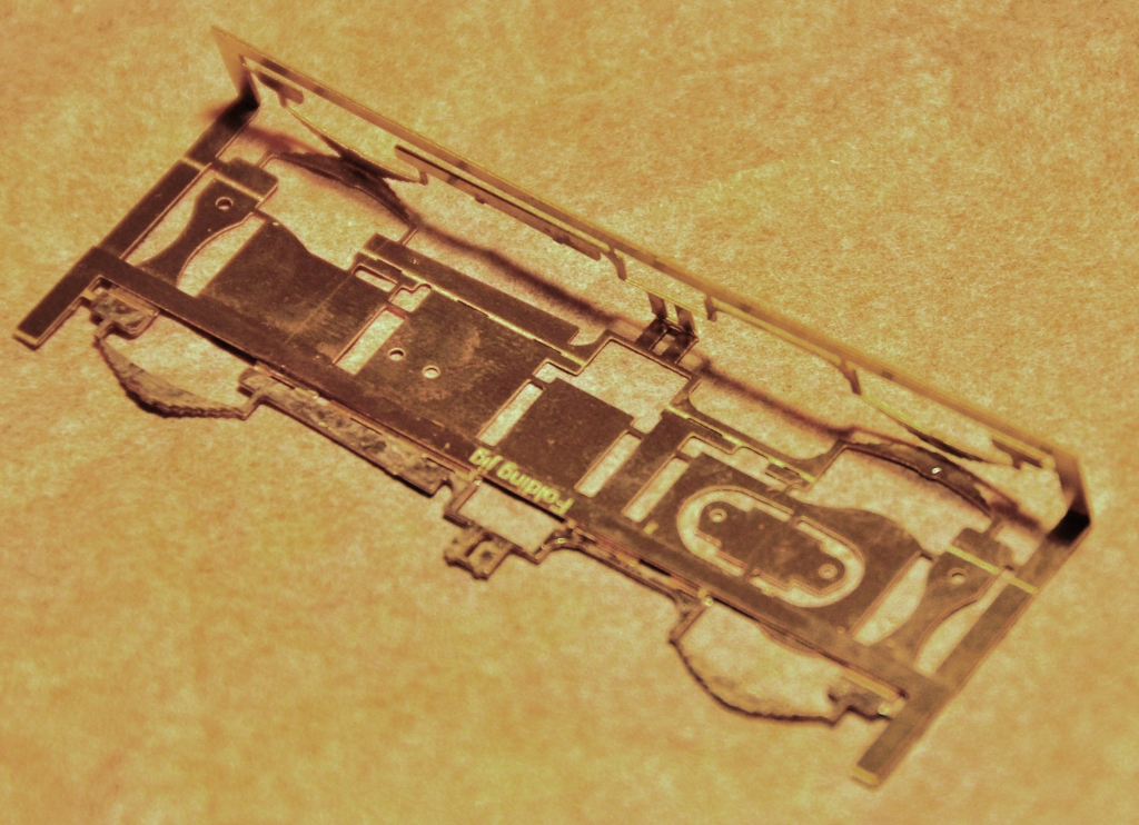
Anyway, this is what the chassis looks like in the flat; note that it is a fold up design – this is inspired by the Mousa Models chassis, so a pinched idea!
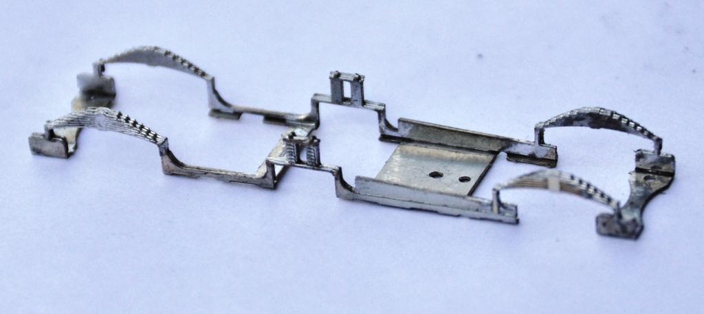
And this is what it looks like with the basic folds made up. What it achieves is really neat, as it is instantly sufficiently stiff to work as a chassis; by the time a couple of further cross braces have been installed the basic chassis is more than robust enough for its life.
My design uses the same slide in hornblocks as utilised by Comet and Brassmasters for their chassis. After a tiny bit of practise, it is possible to size the hole for the hornguides such that these are just too small when etched. This means that with a few strokes of a light cut file on each side, the hornblock becomes a tight sliding fit. Once all of the hornblocks are in, it is then possible to measure the distance between each on both sides of the chassis and also on the corresponding coupling rod. This is done with digital callipers and by the expediency of measuring the distance at its maximum with the callipers facing outwards and then repeating with them facing inwards the average being the actual distance between the centres. I reckon to be able to measure down to 2 or 3 hundredths of a mm, which is rather better than I can build to! Where there are inconsistences, this is dealt with by a few more strokes of the file on the side which needs to be adjusted to change the centre. This needs to be done anyway to turn the tight sliding fit to a snug but smooth fit for the hornblocks to work properly soif the centre does not need to be changed, the file strokes are undertaken equally on both sides of the hornguides.
This does need to be done after the coupling rods have been formed, of which we will see in the next posting. However, the chassis is also designed with a keeper plate to accommodate all of the cosmetic springing to the model and the ashpan sides. This is secured with a series of 12BA screws to enable it to be removed to allow the wheels/axles to be dropped out. A great boon as the model is built and painted.
To make the assembly of this element easier (in fact in this case a lot easier!) I have created a jig that holds the two layers of the laminate in exactly the right position. The jig is chunky enough to avoid distortion as it is folded up and it locates the parts perfectly. In this particular case, the soldering needs to be done with care as there are folds to make after the jig is cut away and it is important not to fill this with solder before hand.
And this is what the keeper plate looks like – it is pretty delicate until it is mounted but fine thereafter.
And the two components assembled look like this. The beginnings of the cylinders are also visible, this is a slide in module that can be removed for assembly and painting (although the scrap tanks were painted fairly simply, so this is not really relevant on this model).