Blog Archives

Still Swapsie – A Signal for Nampara for Hendrawna Part 2
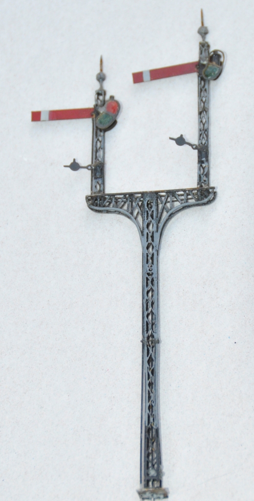
Having assembled the basic post and ensured that it was working, the bolts can be filed away and we get to the following stage.
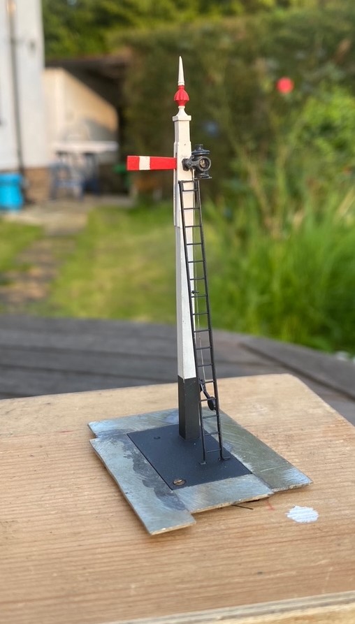
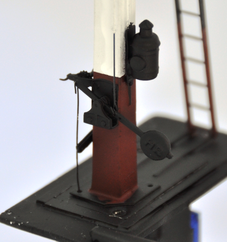
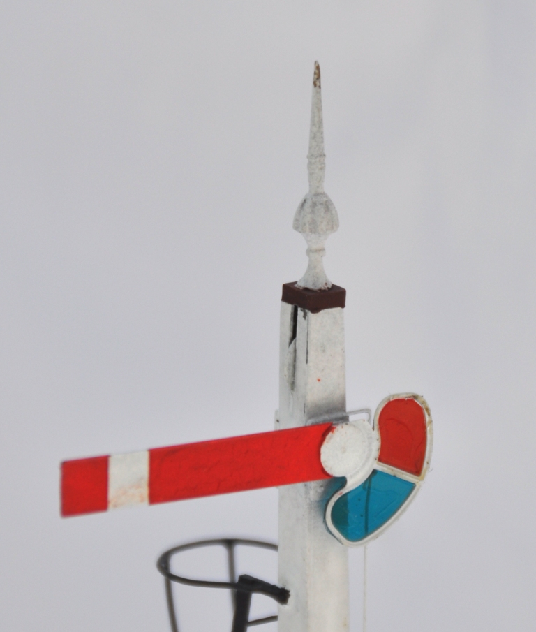
The spectacle plate plate is rather unusual in that it only has one lens which isn’t available via any manufacturer and the arm is notably shorter than I am used to so I had to etch these to suit. Although I could not find a lamp that matched what was on the prototype, I was able to modify a MacKenzie & Holland lamp from MSE to suit. Thereafter, the remaining assembly of the signal was fairly unremarkable.
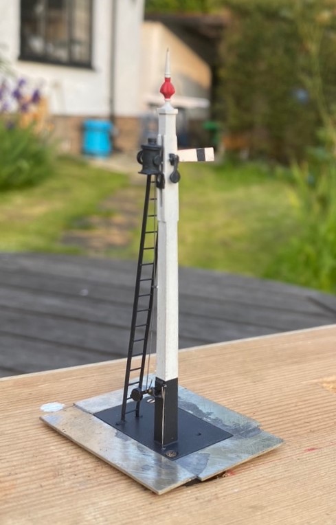
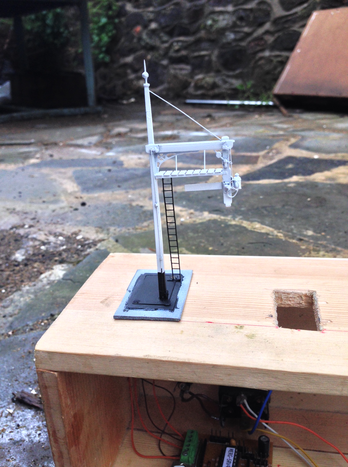
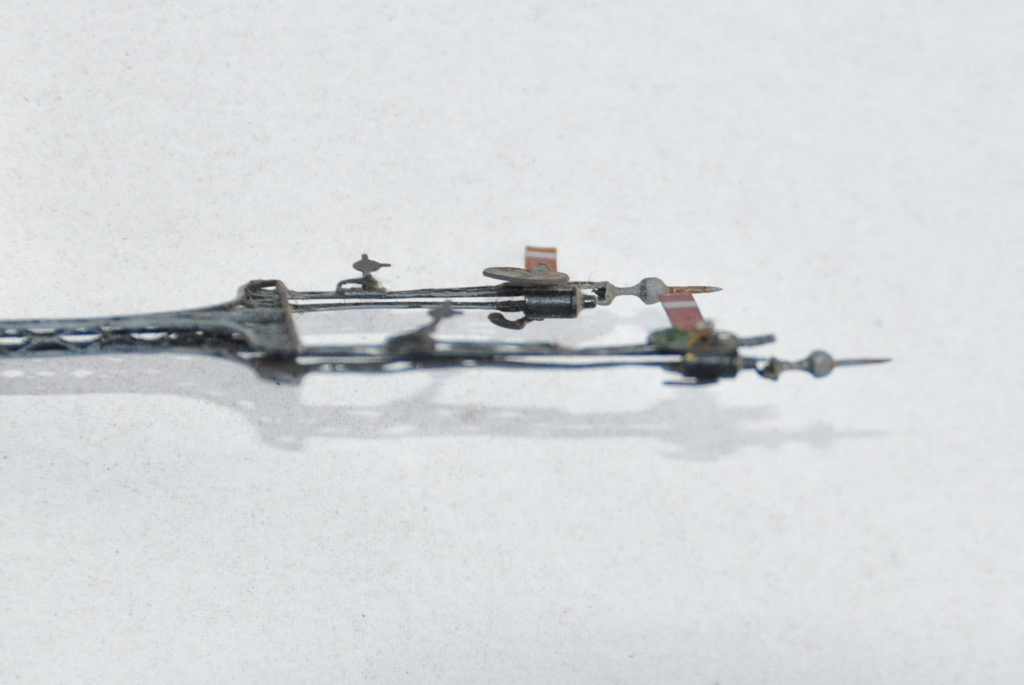
And then once it had been painted, including the unusual red highlighting on the finial that I rather like:
And of course we must have the obligatory video to show that it really does work!
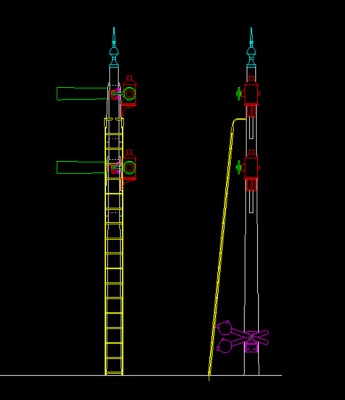
And for those of you that might want it, this is the drawing of the signal, which has two arms, at Didcot.
Swapsie – A Signal for Nampara for Hendrawna (Part 1)
Swapsie – the childish act of swapping things according to Wiktionary.
Do you remember at school swapping a Top Trumps set for a the latest Hot Wheels car or similar? I do! I remember getting roundly b*llocked by my mum for not recognising the value of things I was giving away and (metaphorically I am pleased to say) swapping gold bars for glass beads almost like the Incas and Cortez.
In the world of toy trains, the same happens and is very useful where someone can offer something that you don’t have (or find difficult to make) in return for something you do have. This is one such example. Sitting next to Duncan Redford at an EM Gauge Society/Scalefour Society skills day a few years back demonstrating signal construction a barter was arrived at whereby I would build Duncan a signal in return for him doing some 3D design and printing. I think it is fair to say that neither of us have rushed with our respective shares of the bargain but with the next ExpoEM only a week away, I have shifted into gear to finish the started signal that was my part of the deal.
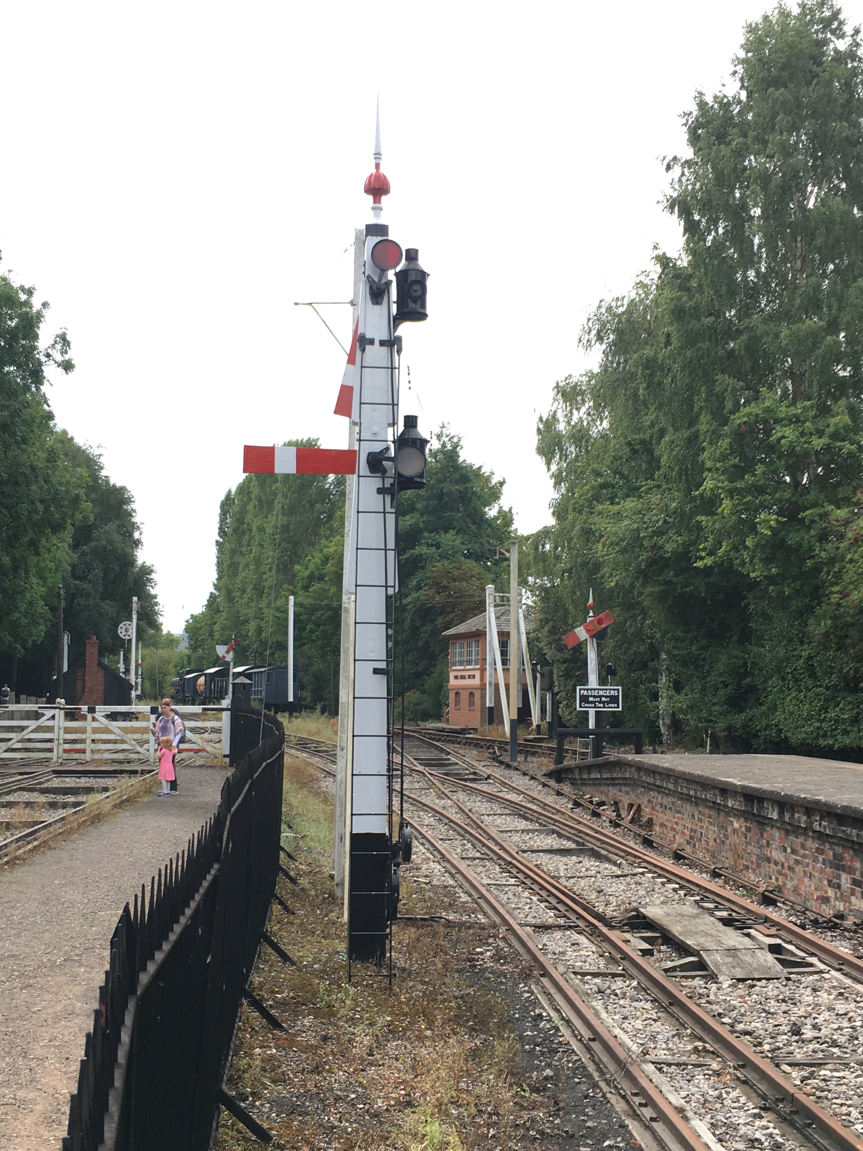
Duncan is building a GWR broad gauge era layout and wanted a close replica of a signal that the GWR Society has recreated at Didcot, but adjusted to have only a single arm. So after coming out in cold sweats about the idea of modelling anything GWR (!!!) I took a look at it. Like many signals, there are differences and similarities with other signals but after a bit of study it became clear that it was sufficiently different that a site visit to Didcot to be required.
Having measured it up including, when no one was looking, a climb to the arm/lamp to measure it, I came home to draw it. I was shocked to find that it was tiny; 3mm/1foot at best and I had a panic attack -had I mucked it up and mis-measured it. Obviously, being a professional surveyor I could not possibly have done that, could I? After a few months, the fear that I had niggled on me and so came about site visit number 2 and a further climb up the signal ladder. Nope, it really is tiny – both the post and the arm are notably smaller than I am used to.

There are several unusual aspects to the signal; the one glass spectacle plate, the tapered arm and the very pronounced stiffening around the slot in the post were all going to be key to capturing the character of the signal. So out came the computer and a small fret was added to an etching order for the arms/spectacle plates. I then formed the basic post from 4mm square section brass which I filed to a taper with a 2.5mm cross section at the top.
Despite having built a few slotted signals already, they are still pretty difficult to get to work well. The difficulty that I have had is to get a soldered joint onto the arm spindle when it is encased in the brass post around it that acts as a heat sink. On a number of occassions the joint has broken and the arm no longer operate. I was determined this was not going to happen this time and have adotped a different approach, by assembling the arm first and then mounting it within the post whilst this was being assembled.
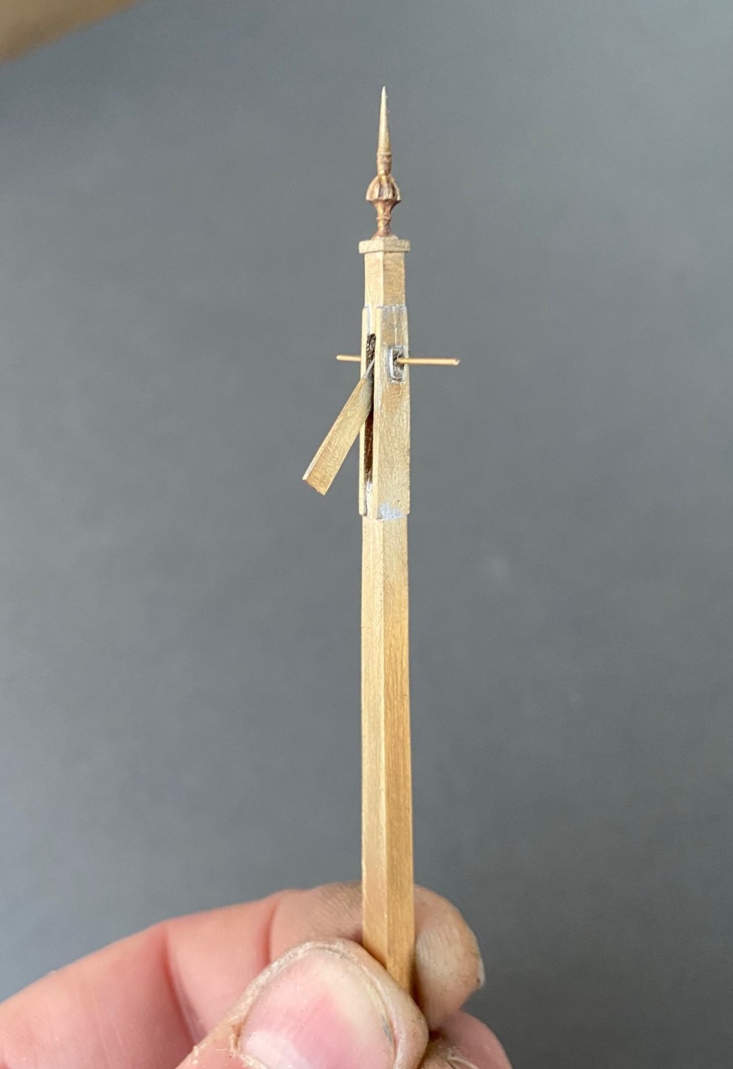
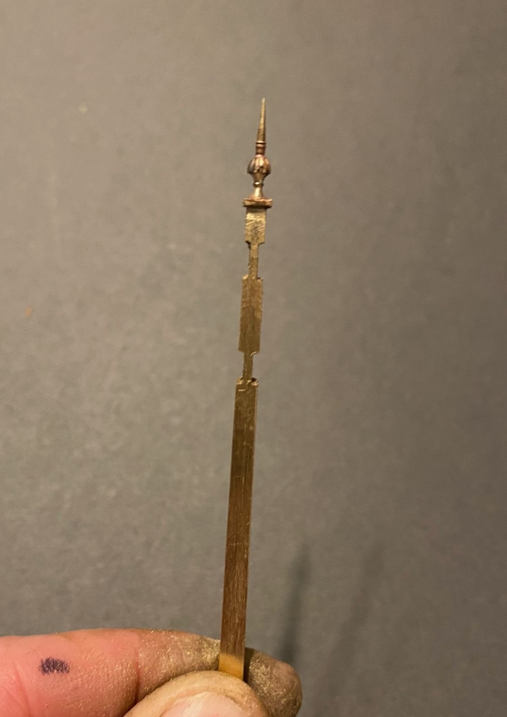
I had filed some 4mm square section into a taper to form the full length of the post. Even though I was about to cut a section of this out, it is necessary to form the full length of the taper so that it is consistent across its full length. Once I was happy with this, i filed two pairs of slots in the outside of the post on oppposing faces. The depth of these was such that the tongue between them was the correct size for the slot in the post. I chose to mount the finial at this stage, with some 296o solder and a lot of heat (from a minature blow torch). This is what it then looked like:
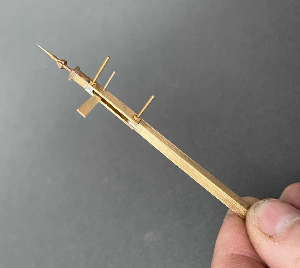
Next, I cut away the block of post that sits between the two filed sections to create a hole in my post. As there is around 2 hours of work to get the post to this point, it is a bit nerve racking chopping it like this! I then cut a pair of 1*4mm brass plate lengths to sit on the tongues and drilled both to receive a 14BA bolt. This was threaded through the first of the plates and adjusted until this a continuation of the taper of the post – this entails some filing of the metal to make the outside face match the post and plate match. It was then soldered in place, again using the 296o solder and a blow torch, to look like this:

The photograph above shows that these plates were wider than the post, in practice the prototype acheived this by planting timbers across these sections but it is easier to do this by way of using the sider plate material.
Temporarily mounting the second plate enables the hole for the arm spindle to be formed through both parts of the arm. The arm was now attached to the spindle with more use of the 296o solder and the use of a couple of minature washers either side of the arm so that I could be confident that the joint would hold.
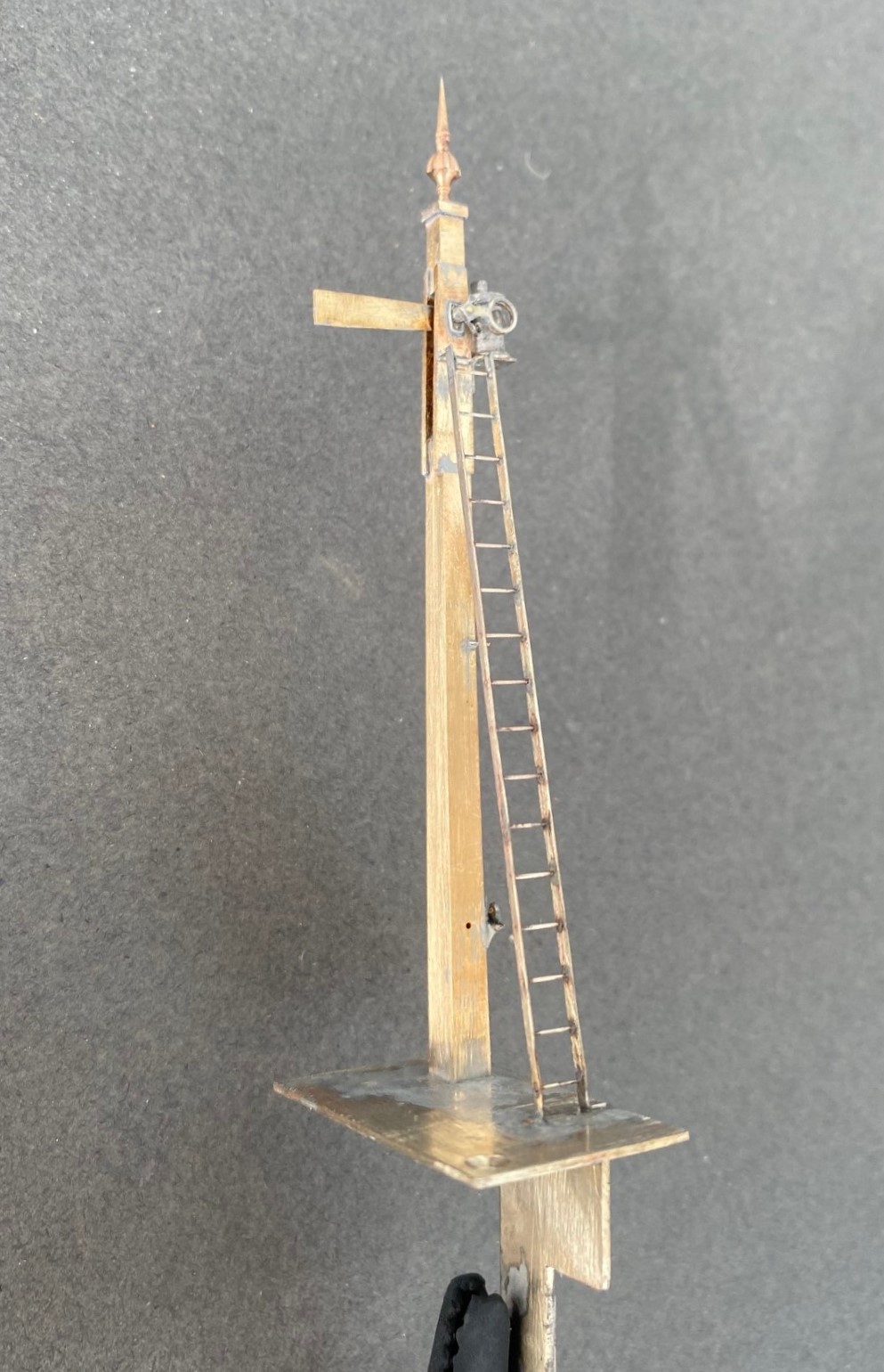
Releasing the second plate now allows the arm/spindle assembly to be inserted and any adjustments made to ensure that it can move freely in the slot by securing the second plate in place with a 14 BA nut. The nuts and bolts are scarificed in the build by leaving them in place for the next step because once I was happy that it was correct I soldered the second plate in place including the nuts and bolts. This time I used 145o solder which meant that it would not disturb the first plate as I was doing this and this is what it then looks like – a slotted post with an arm within that is firmly attached to its spindle!
More to follow; including the second piece of bartering that I know someone is looking out for progress on!
")
Christmas Layout Wiring (Not!)
I promised a number of people that I would be making sure that the layour had at least the main elements wired up over christmas, so that it could at last run. But then it was a bit wet and cold so I did not fancy it out in the summerhouse so I applied rule no 1 – its my trainset!
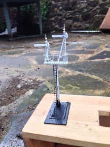
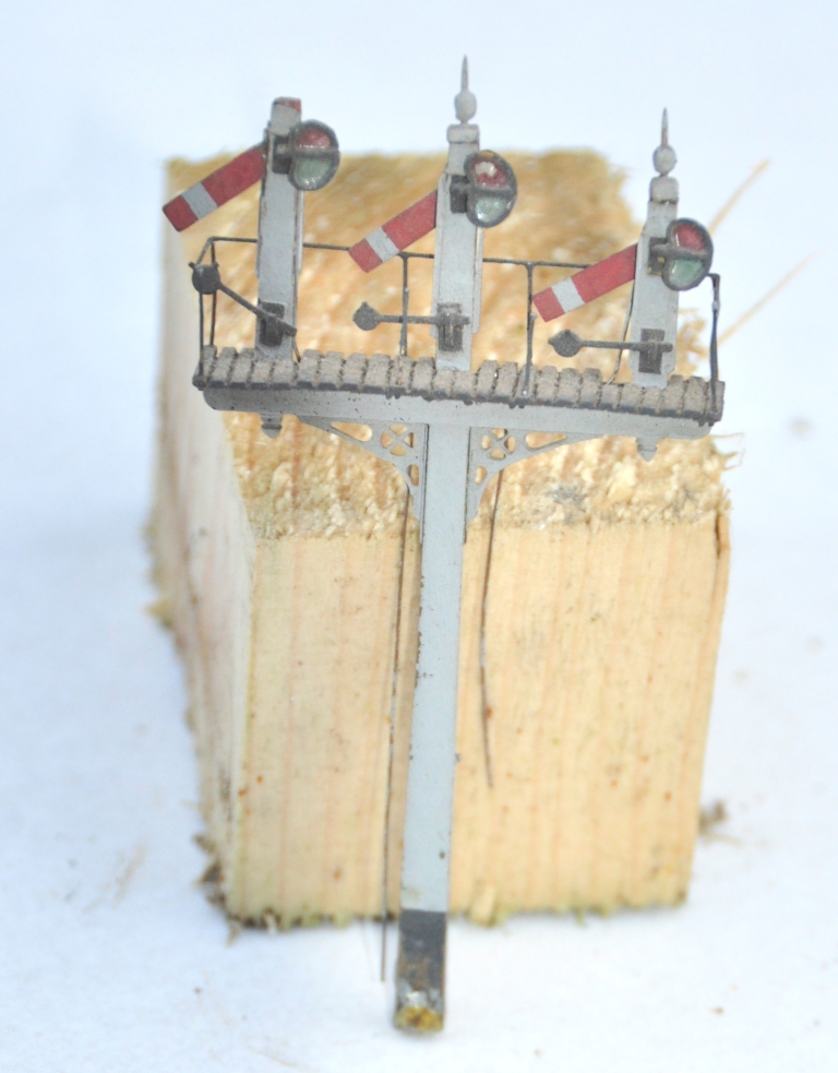
Instead, I stayed at the bench and made a pair of the signals that still remain to be made for Glenmutchkin. The signalling plan has developed very slightly since I originally showed it back here and is shown below (actually this is the artwork for the control panel facia).
The signals that I built were those that control the main loop prior to the shed link – levelrs 27 & 28 – and then the outer starter (that covers both the main loop and the main line) – levers 23, 24, 25 & 26. Only a pair of two doll signals, I thought, they shouldn’t take more than a day or two? Phew, well that wasn’t right; the more you look at the prototypes, the more you find there is to model!
Having created much of my own etchings and castings for MacKenzie & Holland signals I have obviously made good use of these. In this case, the small brackets, arms, ladders and castings.
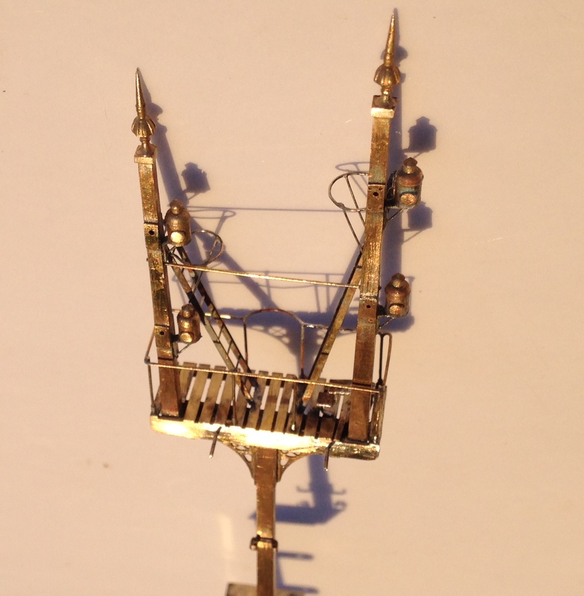
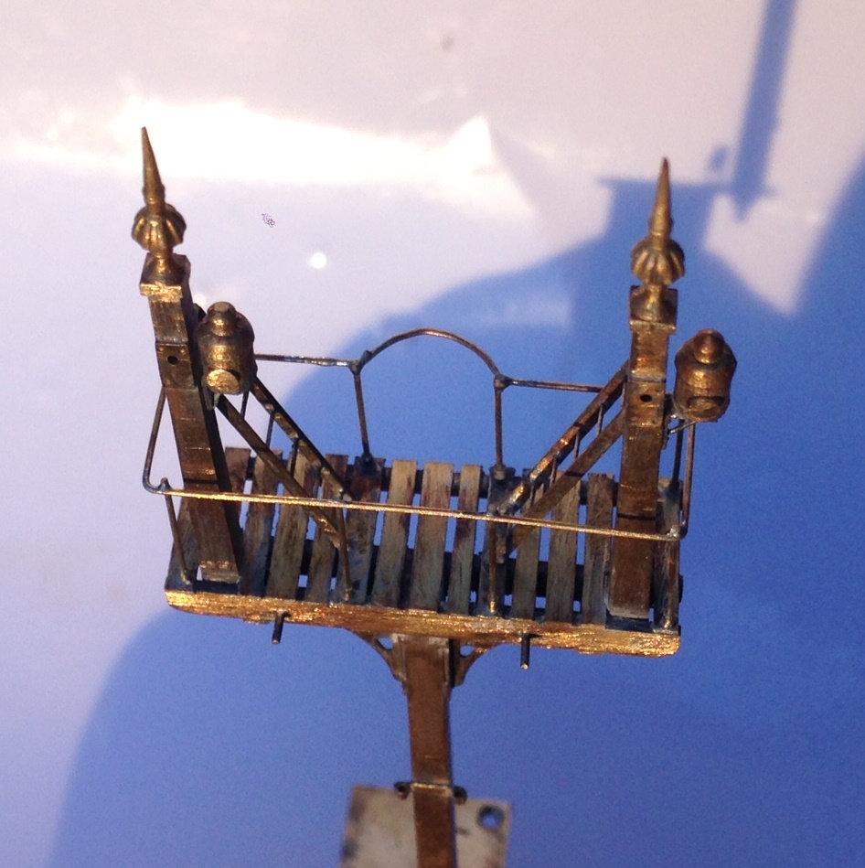
Both of the signals have used the small brackets to create smallish landings. The smaller of the two signals has only one arm per doll, the larger two. The dolls and the posts are made up of square brass section which is filed to a taper – a certain amount of elbow grease is needed to acheive this! The posts are then sandwiched between some transom beams that also clasp the doll post – this is all soldered with a high melt solder to stop it ungumming later.

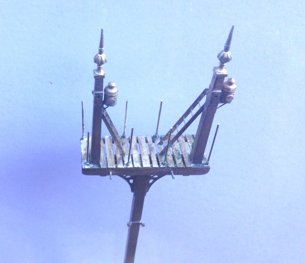
The brackets are then offered up from below, with scrap etch forming the bearing plates to pick up the transomes. In the etch I also included smaller brackets to pick up the free end of the landing, along with the landing itself. This gets you to the stage shown above.
But this is not the half of it on a signal, there are the finials, lamp brackets, lamps, cross stays, access steps, access ladders, pivot plates, handrails, operating cams, safety hoops and ladder still to do………..
 .
.
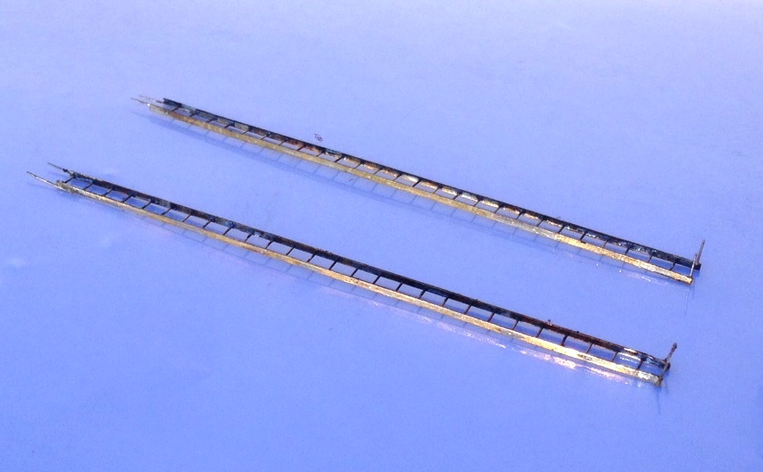
In a departure from my previous practise, I made the main ladders detachable (they will be held with the wire that can be seen in the pictures being turned over in secret pockets. I am also going to paint this prior to the final assembly; which will mean some touching uo of the painting later but I hope will make it easier.
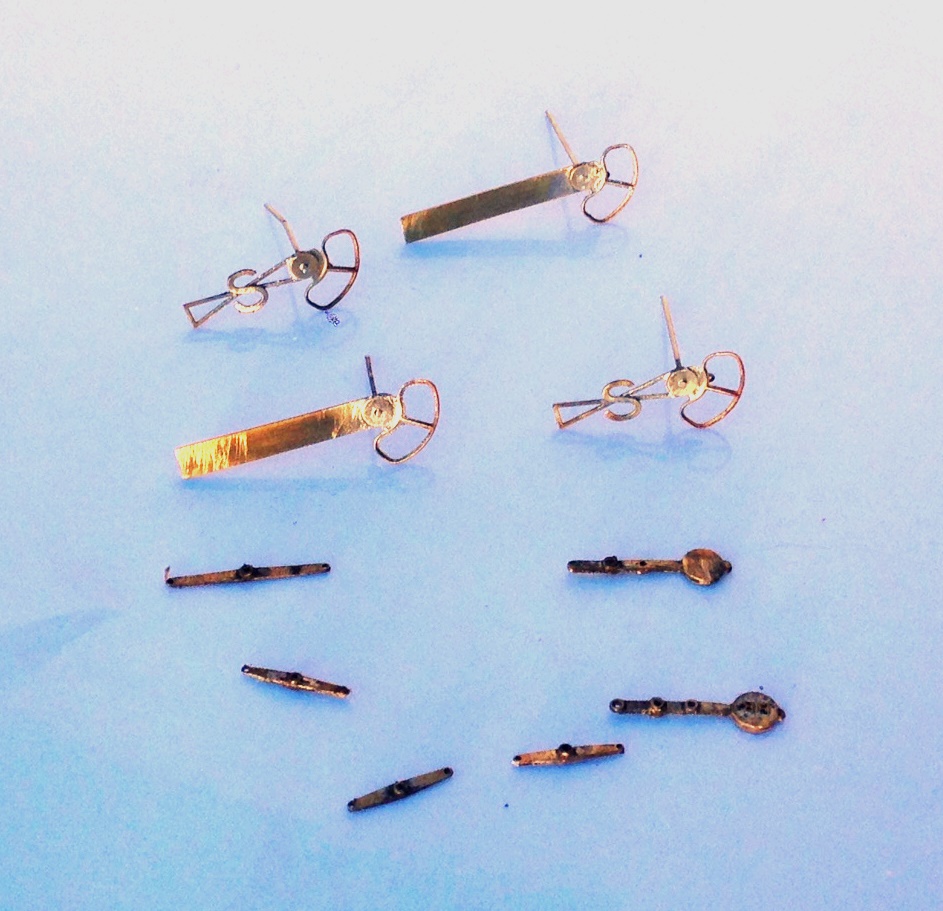
And of course, I had to sign them with these rather nice custom name plaques from NBR 4mm Developments.
This is the first time that I have used the brackets in signal making and I was pretty chuffed with how they have come out. This is where things presently stand and we head for the paint shops tomorrow…….
A new website for Miscellany Models
I will be making at least some of the items that I have been developing available for sale.
Therefore, I have set up a separate website entitled Miscellany Models that shows what is available, how to get them and (when I get some time to do it) will become a repository for prototype information that I have on the items I have made, construction/finished photographs and instructions.
You can find this website here. If you look hard, you will see some hints as to what other things I have been working on and are expected to be made available in due course.
Progress on Benfieldside’s Signals
Back in February (where does the time go?) I put some pictures up of some signals I was restoring for Benfieldside.
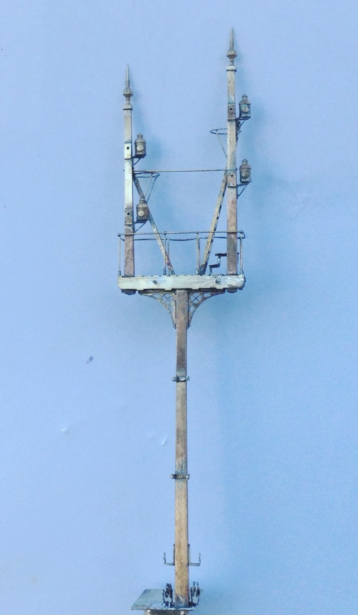
Matters have progressed; although I did find that one signal was beyond repair and both of the remaining needed quite a liot of work to do to them as all of the landings, ladders and in some cases balance arms/finials had dissappeared over time. They are not quite finished, as the final painting, weathering and installation of the spectacle plate glass is still to be done. However, this is what they look like:
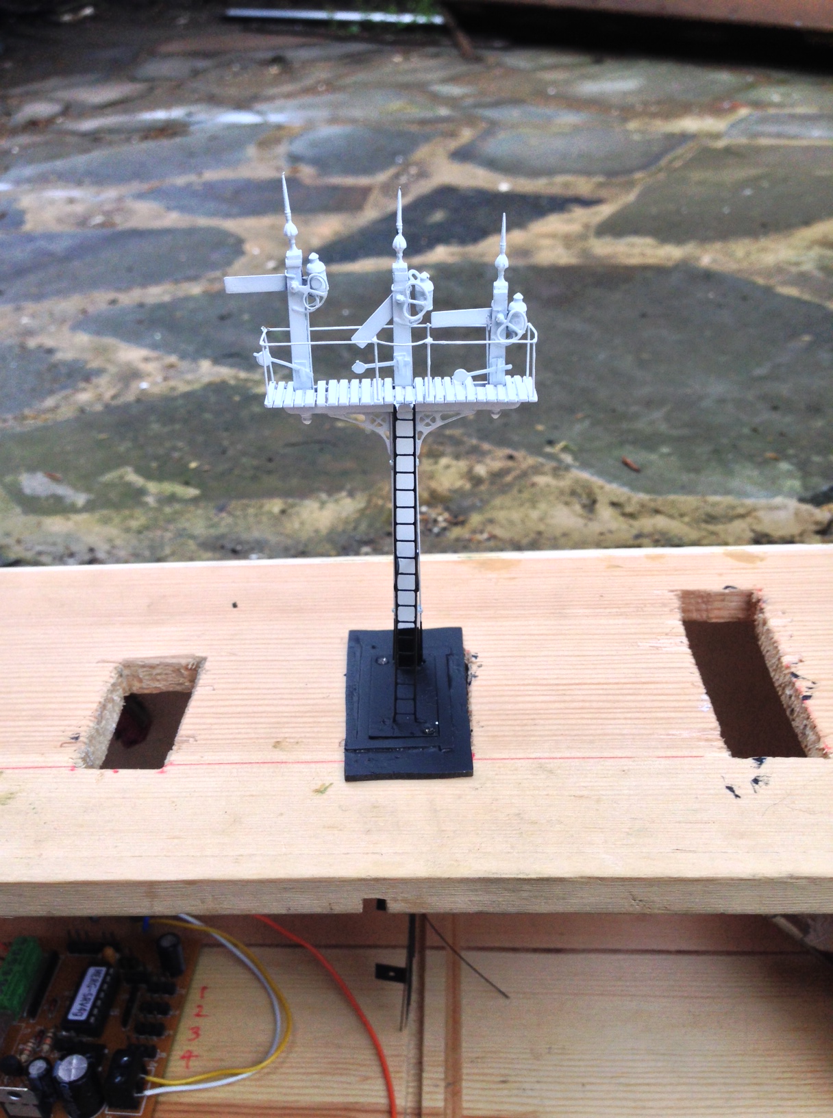
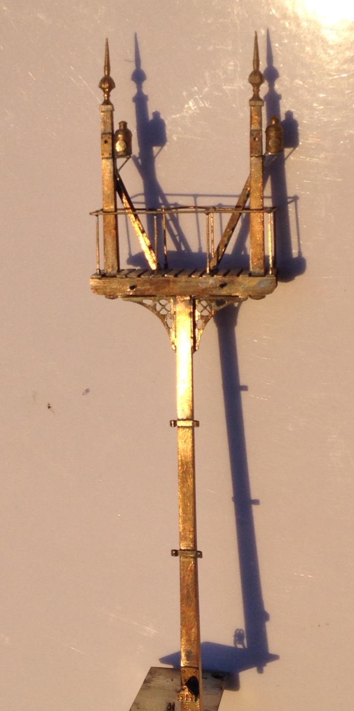
In addition to the three signals to be restored, I have a number of others which were missing altogether. Here is the first of them:
More on my casting and etching
We haven’t had an update on the etching and mastering that I have been doing for the signals for a while.
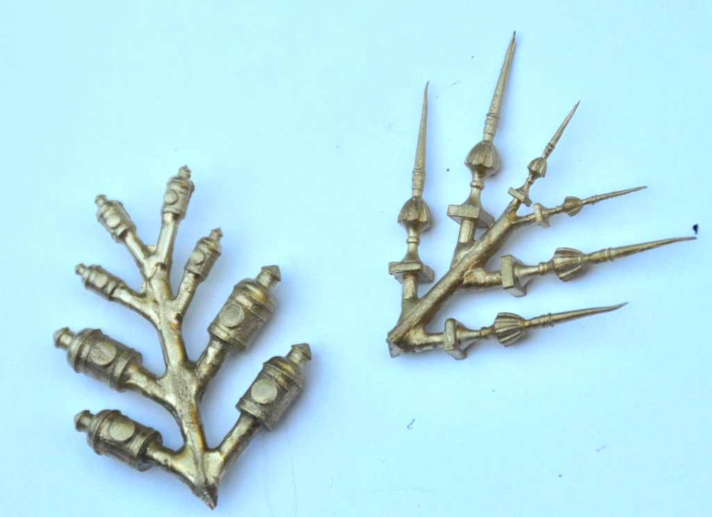
Well, I have had both the rapid-prototype masters and etching in. Using the former, I have also had my first set of lost wax casting done – in this case for the lamps and finials. This is what they look like – which I think is pretty good and a lot better than the white metal ones from MSE.
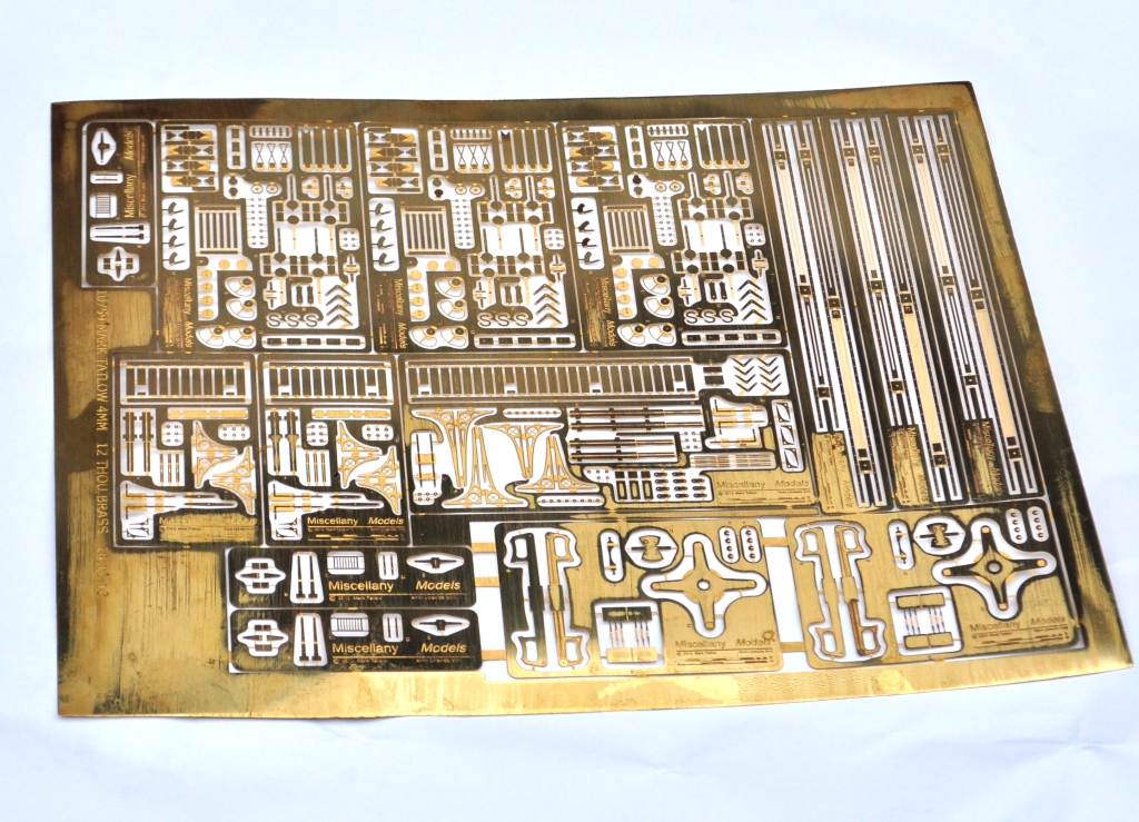
and the etching looks like this – brackets, arms, ladders and a few other bits and pieces.
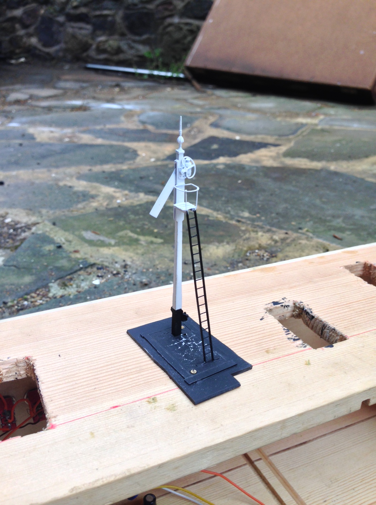
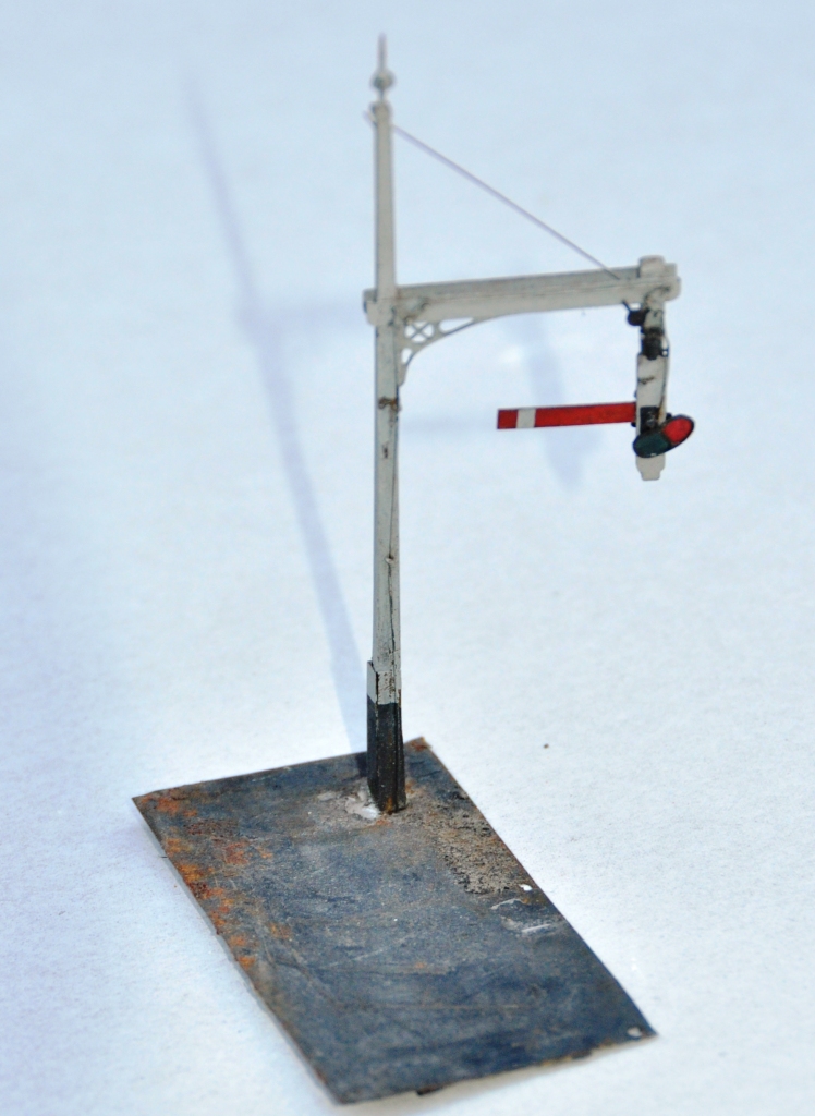
So it was time to make a signal – in this case a fairly simple single arm Highland signal. So using a post from Lochgorm and then my parts for the arms, spectacle plates, windlass, balance levers, ladders, finials and lamp, this is what it has come out like:


and the castings close up looked like this.
So all in all, I am pretty chuffed!
It does mean that I think there is some more signal building to come on these pages……….
One good turn leads to another…………
I managed to get most of another day in Tim & Julian’s joinery workshop. With the assistance of Tim, we managed to get the three boards assembled with pattern maker’s dowels; along with the beginnings of the ground profiles.
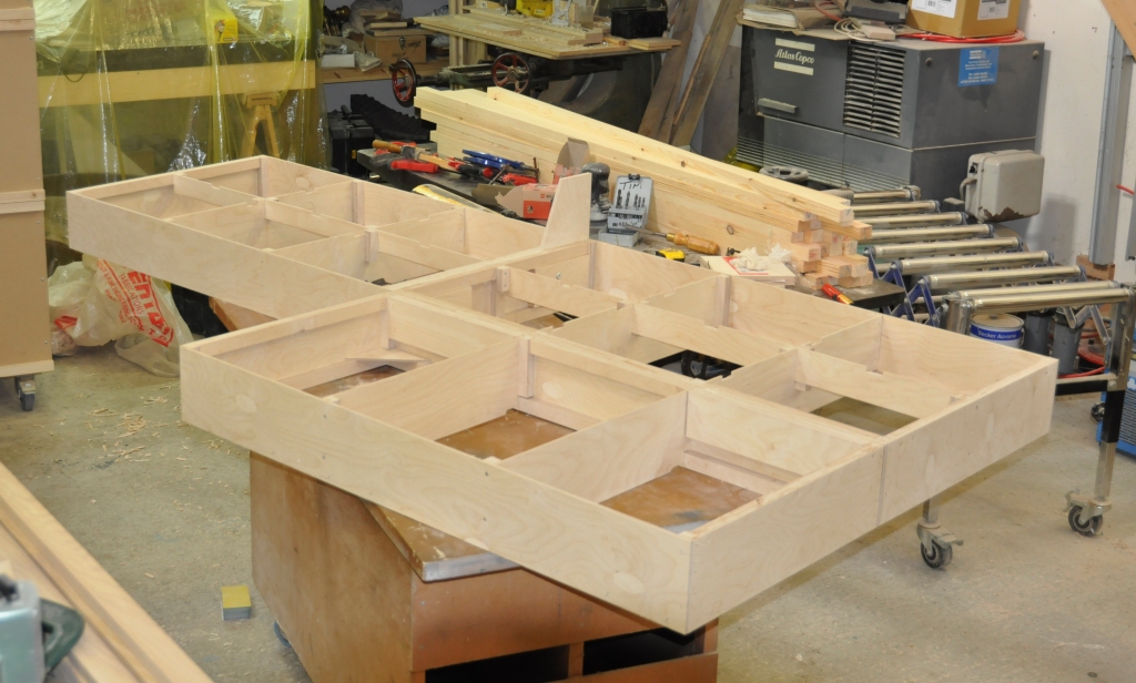
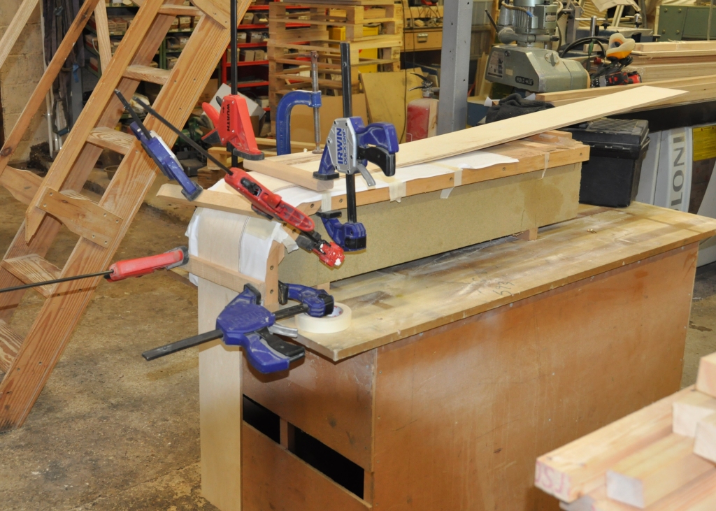
A start was also made on the last of the four boards that will form the main station area. I didn’t want an ordinary square board on the corner as the layout will be viewed both front on and from the end. Therefore, we have had to profile the corner piece around a mould.
But all this help does have a price……………………. Tim and Julian have recently acquired Benfieldside. This rather exquisite layout was built by Martin Wright and was subsequently owned by John James. If you want to see how good it is, find yourself MRJ 38 and you will see what I mean!
Over the years, the layout has suffered some damage so it is going to need to be restored. This is where the use of Tim and Julian’s joinery shop ceases to be free – there are a number of damaged signals and even more that are missing altogether. My brief is restore those that still exist and to set them up for servo operation. Here are the first three; all of which have different issues.
This one has a shattered post and is missing its access gantry/ladder. In addition, the signal arm has become detached and as the signal is slotted (ie the arm is within a slot in the post), this is going to be quite difficult to fix in situ.
This one also suffers from problems associated with the slotting – when Martin made this he only used lattice work for the front and back in order to provide a slot for the arm. This however has made the signal very weak. In addition, the gantry and ladder are missing.
One of the arms us detached from its operating arm, its ladder and finial are also missing.
Fortunately, the North Eastern used Mackenzie & Holland as their signal suppliers as well as the Highland. Therefore, I will get to use my etches! Anyway, the signals have been stripped and restoration has started; a post next week will show how they are coming along.
More 3 D Printing
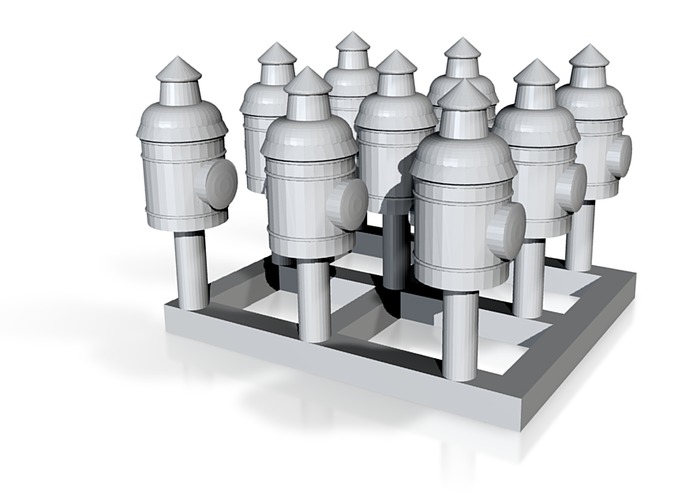
Whilst my orders for earlier work are underway, I have done a bit more drawing and have now drafted up some lamps for the signals; as below:
I have also managed to sort out a drawing that I did some time ago for a water column. The larger of the models for 3 D printing need to be hollowed out (to save on the printing medium, which is charged for by its volume). This took some time to get right, as I had multiple different parts I was working on.
So these have also be sent of to Shapeways for printing. As before, I will use the lamps as masters for lost wax casting (another new trick to learn!) but the water column will be used as a master for some resin casting (the old dog really is going for lots of new tricks) – it will also need an etch for its operating arm.
However, lets see how good they come back first – as I think I am probably counting chickens prematurely here……….
More on the etching and hopefully some 3-D printing
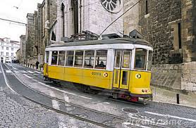
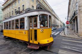
I received the test etch back from the etchers and after a family holiday (Lisbon – hot but great and with fab trams – see below………) I have had a chance to look at it.
I still have some things to learn, as where I have drawn things up at 4mm the smaller elements have come out a bit fine. so things like the framing around spectacle plates or the cross to the centre of the brackets is a bit too delicate to use. Also, I made a number of the fold lines and the holes are a bit too small so need to be drilled out. Thus, whilst the 4mm ones are usable, they can be done better so I am going to edit the etch.
I also included the signal arms etch at 7mm and this is much better. Whilst one or two elements would benefit from a slight redraft, it is definitely usable and therefore I am just in the process of some 7mm modelling (excommunication from the Scalefour Society?). I’ll get some posts up when I can get it a bit further.
In the meantime, I have also managed to have a bash at some 3-D modelling on CAD to get some finials made up. The idea will be to do an initial set via 3-D printing and then to use these to make some lost wax castings. Whilst these are available via MSE as a whitemetal casting, they are very delicate and will last very little time in my clumsy mits. I will do a lamp via the same route for the same reason.
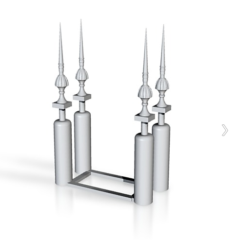
Anyway, this is what the 3-D model looks like (actually the final version has a sprue coming of the top to support the top of the finial but it rather blocks out what it is you are looking at):
And to give a flavour of the trams in Lisbon:

Etching Artwork
I have not actually picked up a modelling knife or soldering iron for a couple of weeks now; largely because I got a bit of a bug for sorting out the etch artwork.
I have now completed, I hope, all of the artwork I will need for all of the signals that will be required on Glenmutchkin. Indeed, it should do all the signals I and just about anyone else ever needs for any scheme based on the Highland era!!!!
I am fortunate that I have a couple of an 1895 McKenzie & Holland catalogue and a further partial copy from a bit later. I have also been provided with a number of really good drawings of bracket signals from M&H, prompted by my ramblings on the web. This has given me with a pretty good handle on how they were constructed and I can draw up rather more comprehensive (and a little more specific to the Highland) artwork than are available form any of the other sources.
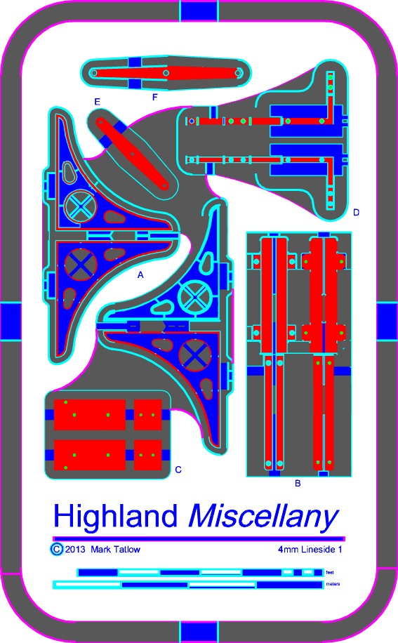
So this is what I have come up with. Firstly, an etch of all of the arms, balance weights and a track mechanism for raising the lamp to the top of the post (I think this was peculiar to the Highland):
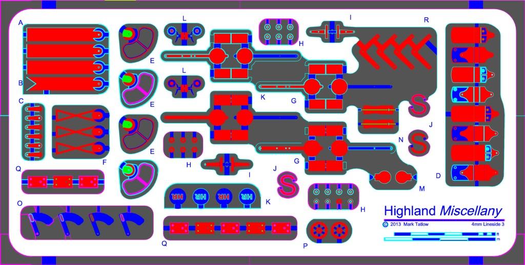
and then an etch that includes the large brackets used for the multi-doll signals and all of the support brackets and landing.
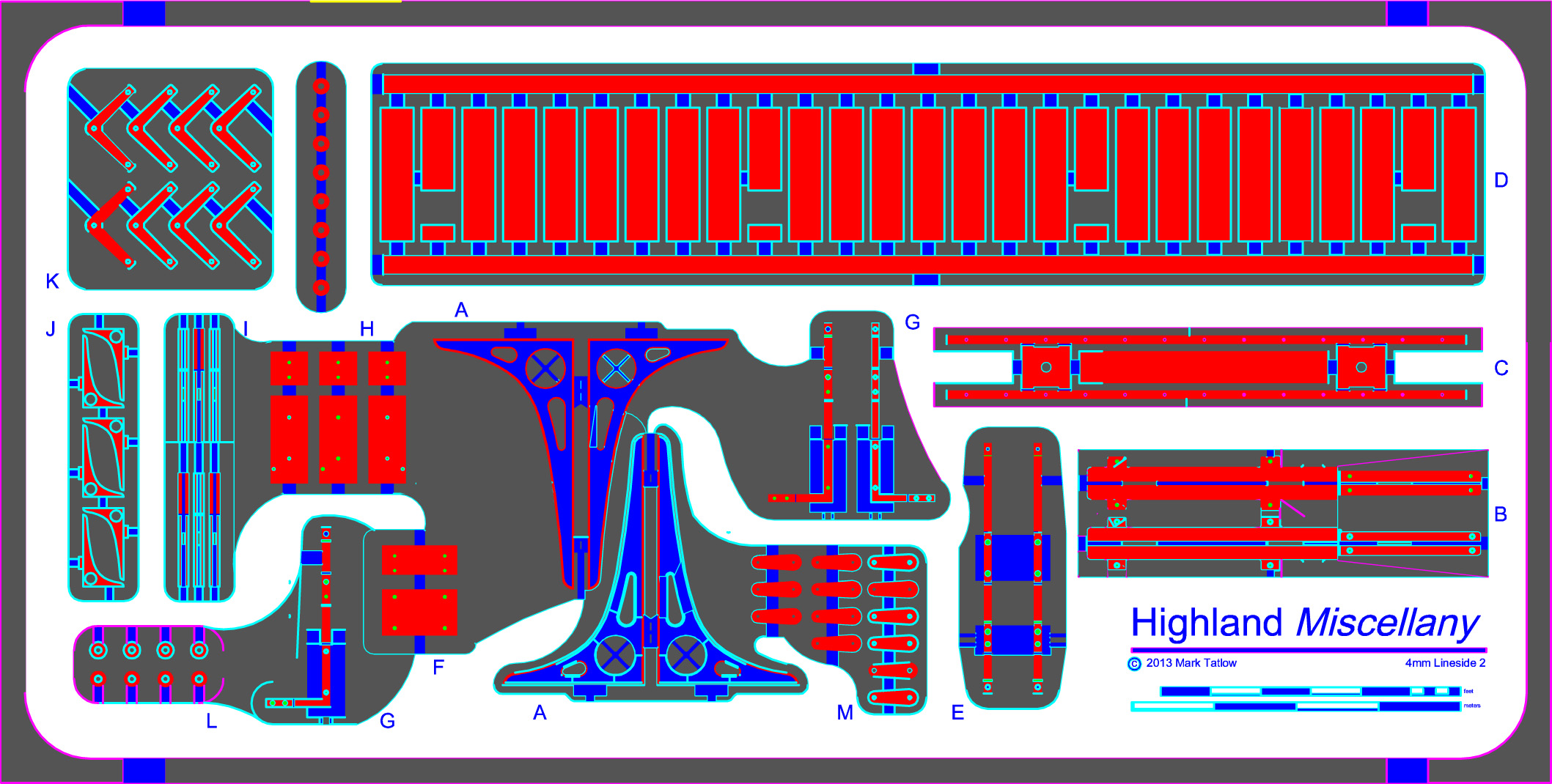
and this one is the smaller bracket; used on twin doll signals:
I have been recommended to use PPD as a first port of call for etching, so they have been winged off tonight. Lets see what a week or so brings us…………..
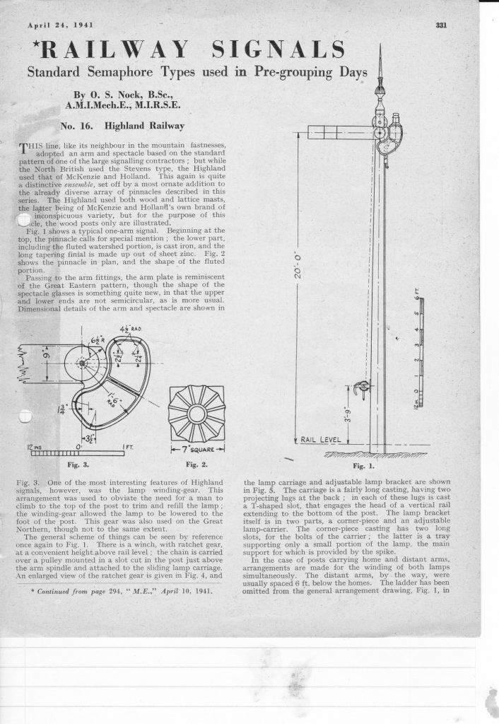
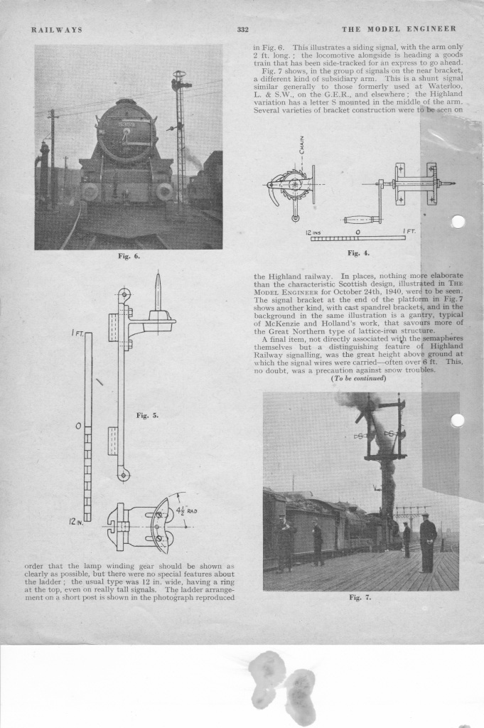
As this is now out of copyright, an article by OS Nock on the Highland’s signals from the Model Engineer might be of interest too – it may even show what I am trying to make in the etchings a little more clearly.
And for my next task, I am going to have another bash at the water column and the finial; more on this when I think I have been successful!
