Blog Archives

Something Fishy…….
Fish was an important traffic to the Highland Railway and as a result fish trucks were one of their most numerous classes of wagons. Given that Glenmutchkin is conceived to be on the coast, fish traffic will also be an important feature on the model too. There is to be a line to an off-scene harbour, so that I can justify a significant traffic. I already have a shortish train of fish vehicles, mostly open trucks, but I definitely need more
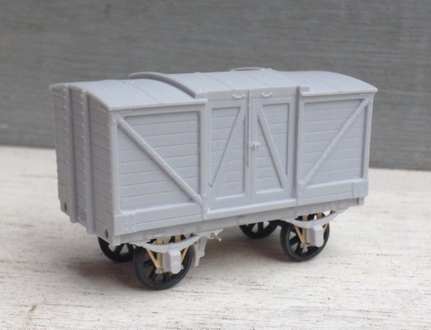
Back in April, I reviewed the Mousa Models LNWR covered van, which I was generally impressed with. Buoyed with this I spent portions of the last couple of weekends making a pair of the same manufacturer’s HR Drummond Fish Trucks. The kit is arranged for the variant that had a centre drop door, but there was an alternative variant with full length drop sides and at least some acquired morton brakes during their life. Thus, there are a few modifications that can be made if you wish.
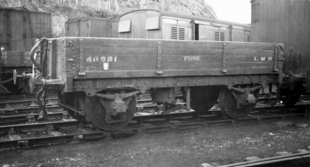
The above is a full drop side version of the fish truck at (I think) Kyle (AB McLeod, HRS Collection).
Having built a few Mousa Models kits and however regretful it is, I was not surprised to find there were no instructions included in the kit. This is a pain as there is enough going on with the model to justify some guidance and anyone who does not have my father’s book will struggle. Unfortunately, I did not take any mid way through photographs before I realised that some notes on its construction would be of assistance, but hopefully these notes and the pictures of the completed model will be helpful.
A first issue I discovered was that the resin casting was a touch distorted. The ends in particular bowed into the well of the wagon and the whole wagon had a slight twist to it. This is a common problem with resin kits but with care can easily be corrected. Put the body casting in hot water – as hot as you can tolerate with hands (so less than boiling – 40C is about right) and it softens sufficient to allow these to be corrected.
Although the resolution quality of the LNWR van was good, the quality of the prints that formed the masters for these resin castings was not nearly good enough. Significant portions of them looked as if they were sand castings and did not look real. The body sides were better and were capable of being improved to an acceptable standard with some work with wet and dry sand paper. The solebars were worse, possibly because they received less effort to tidy them up prior to being used as a master. I managed to tidy it up a bit more in the areas that were more free of rivet heads, but above the W irons this was not possible and will have to be masked with some weathering.
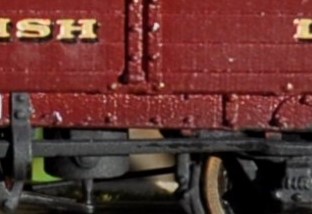
The roughness of the print is apparent to the solebar
The kit is conceived with sprung W-irons to Mousa Models normal design – details of the assembly of which can be found in my previous blog post. However, these need to be carefully lined up to the bolts on the outside of the solebars as the locating slots to the underside are oversized and allow too much slop. It is also necessary to use the Brassmasters axle spacing jig to ensure that the axles are parallel and correctly spaced.
As I noted previously, Mousa Models seem to wish to use resin parts for as much of their recent kits as possible. There were only a few parts where this was a problem on the LNWR van but the problem is rather worse on these fish trucks due to the additional elements of detail that they contain. Had some of the components been produced as etched parts, they would have been a lot more durable without compromising fidelity. I replaced the brake levers, coupling hooks, vacuum brake plunger and brake tie bars with etched components or wire but if I were doing any more of these, I would also swap the brake blocks/hangers because I have managed to damage two of these. Masokits do some that are suitable, although there may be others too that I do not know of.
Page 147 of the carriages and wagons book shows a drawing of how the Drummond patent brake levers operated. In this, it can be seen that there was a long lever running to the right hand end from the fulcrum of the “scotch brake”. This then met a smaller lever that operated in a cam arrangement on the long lever but also connected through a rod to the other side of the wagon. On this side, there was another short lever (so appeared on the left hand end on this side). In the kit, the brake lever is rather crude due to the need to beef it up so that it is durable but even then it is very vulnerable. Furthermore, there is a second long lever, which is not correct at all. Instead, I made up a rod from brass and utilised an etch from the Highland Railway Society.
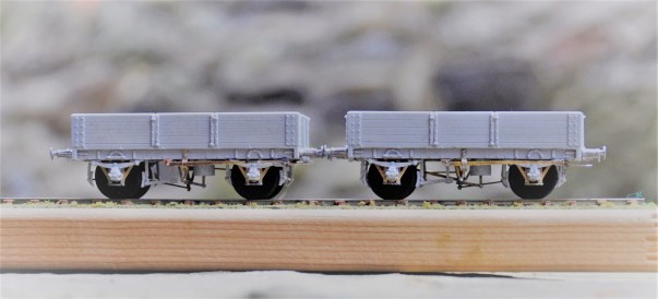
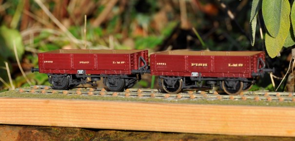
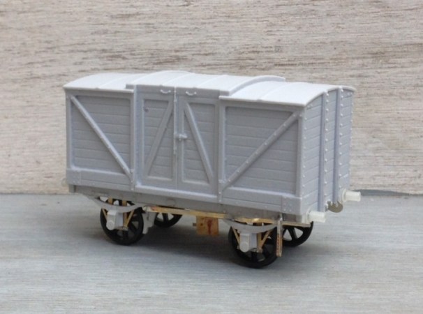
The principal side to the wagons, showing the missing brake lever now provided by way of a Highland Railway Society etching.
The patent braking system was, however, found to be unsafe because one side could be operated without the user on the other realising it (it cost someone some fingers, I believe) and the Board of Trade banned them for new construction. Therefore, many wagons had their braking arrangements changed, either by the use of full length levers and a ratchet or even a full change to morton brakes. I converted one of my wagons to the former by the use of some etched levers from 51L and an extra V hanger from the scrapbox.
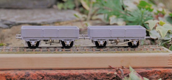
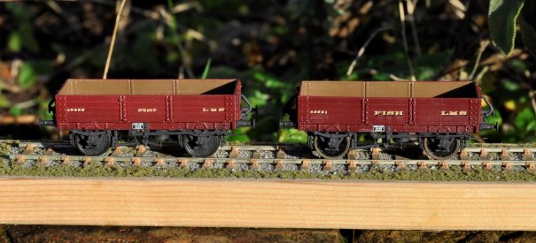
And now the subsidiary side to the wagons, showing the Drummond Patent Brake lever to the left hand vehicle and a replacement long lever on the right hand vehicle.
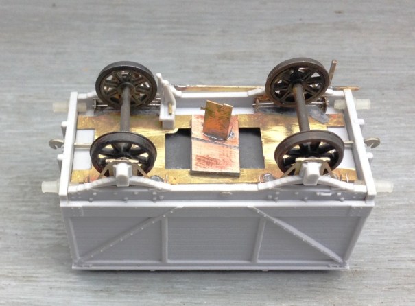
I also took the view that the buffers were too delicate to survive in use and therefore swapped them for Drummond buffers available from the Highland Railway Society. I also found it necessary to cram the whole of the underside of the chassis with lead, to get the wagon’s weight to a level that would operate the wagon’s springs.
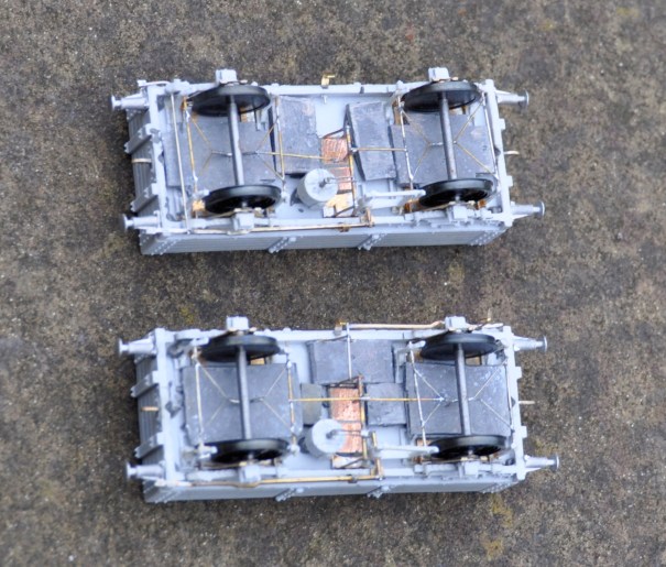
The underside – the rod to the Drummond brake is visible to the left hand end of the top vehicle.
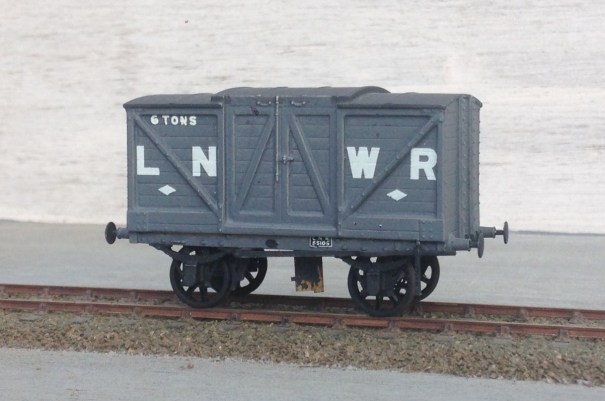
Although these will have been green with yellow lettering for much of their lives, I chose to do them in LMS crimson lake. Rather fine they look too! When carrying fish boxes, it is known that turfs were used to provide thermal insulation around the fish for the journey but my guess is that this was covered within tarpaulins. I have tended to find that the paper tarpulians (Smiths etc) are not that durable so I need to do some experimenting on alternatives – I do have something in mind. That will be for another post though!
Painted (well I seem to have missed the rims!) and awaiting weathering
All in all, these are quite attractive vehicles, very core to the required stock for Portchullin and the kits are a pretty good – but they could be better and easier to build if Mousa models had dealt with what are relatively obvious points.

Dirty Models……..
Now, I wonder if that heading will gather a few extra viewings………..?
As I have mentioned before on this blog, every few months I catch up with a group of mates to have a joint modelling session. The general gist of these is a combination of banter, a bit of modelling, more banter, a visit to the pub, even banter, a bit more modelling and all nicely rounded off with some more banter.
Last week saw us on the south coast to do some weathering – or rather some of us. One of our number was preparing for their imminent marriage whereas Oly (one half of OTCM) felt his budding TV stardoom was a sufficient excuse to hang up his airbrush. We do fear that Oly may not return to the fold; preferring instead to do his modelling with Brad, Leonardo and Denzil once he makes his silver screen debut in the autumn – don’t forget your roots Oly……….
We were all concentrating on different things; Peter constructed the better part of a bridge for his Aultbea layout and Chris was weathering some rather neat little shunters. For my part, I concentrated on weathering some of the stock that I have been building lately (and sometimes not so lately!):
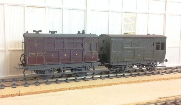
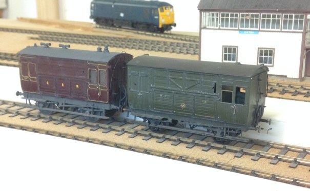
First up is a pair of horseboxes. On the right is my HR version based on a Microrail kit – still in need of some glazing. On the left is the Caledonian’s equivalent based on a kit from by Spratt & Winkle. Both are in their pre-group livery as can be seen. As such stock was used in passenger trains, I have sought to give them an aged but largely cleaned feel – with the dirt largely present around ironwork and difficult to clean spots.
Having mucked up the weathering of some brake vans at the previous weathering session, I was also keen to get these corrected. This is where I have got with them.
As can be seen, I do not follow the school of thought that the pre-group or 1920’s era stock was constantly pristine. If you bother to look at contemporary photographs, little is clean and some of it is downright grubby. Railways in the steam era were very dirty places; it is inevitable where so much coal, ash and smoke prevail. Furthermore, I can not see even the most houseproud of railway companies regularly (or probably ever) cleaning their goods stock and most of these show stock that is care worn and soiled. This is the feel I am seeking to capture; not the utterly neglected and on its last legs look of the final days of steam but of railway materials that earn a living the hard way.
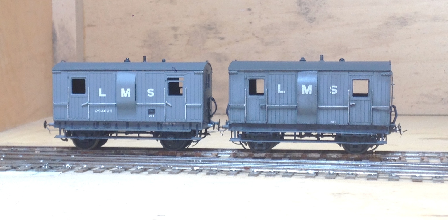
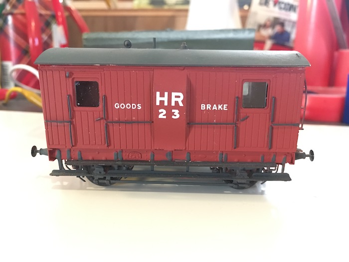
The pair of brake vans above are to HR diagram 39 from 1922 and are from a Lochgorm Models kit. There is some doubt whether they were delivered in 1922, as there are no known pictures of any of them in HR livery. However, I applying the “its my trainset rule” a number of modellers have painted them in Highland colours; including Paul Bannerman whose example is below.
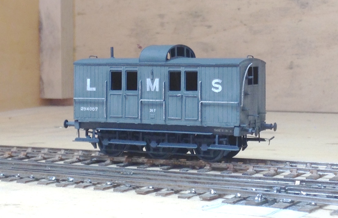
The other highland brake van I weathered was the diagram 38 brake van. This originates from a Microrail kit and may well still be available from David Geen occasionally at shows as he does own the rights to the artwork. I have modified this with the early pattern roof look outs. These allowed the guard to look over the train around the twisting curves that characterised parts of the Highland’s system. However, there were complaints about whacked heads as the guards came up and down the steps to look onto the lookouts and as a result they were modified with approach cutouts on the roof – take a look at the Lochgorm’s page above to see an example.
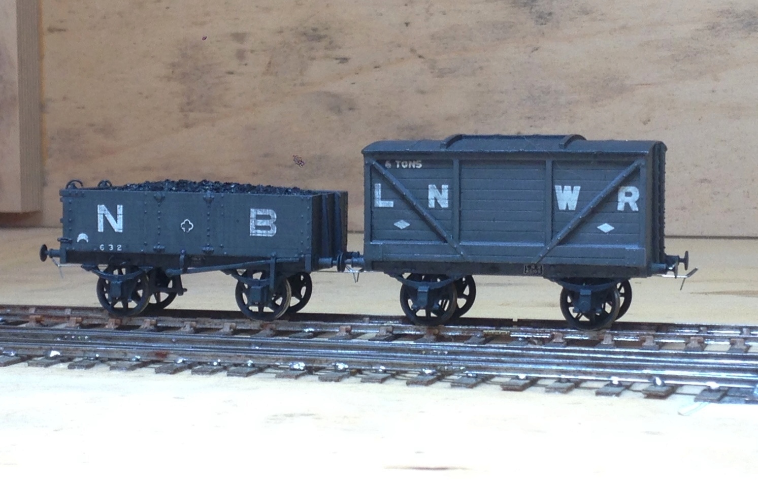
Next up on the weathering front were some wagons and NPCS. The first pictures being the weathering to a couple of the items I have described in the pages here – the Oxford Rail NB jubilee wagon and the Mousa Models LNWR van.
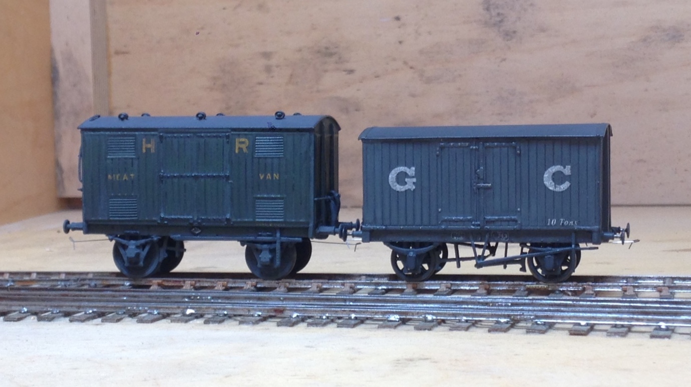
And then some rather more ancient models of mine, a Highland Railway meat van from a Sutherland Castings kit and a GC van from another Mousa Models kit.
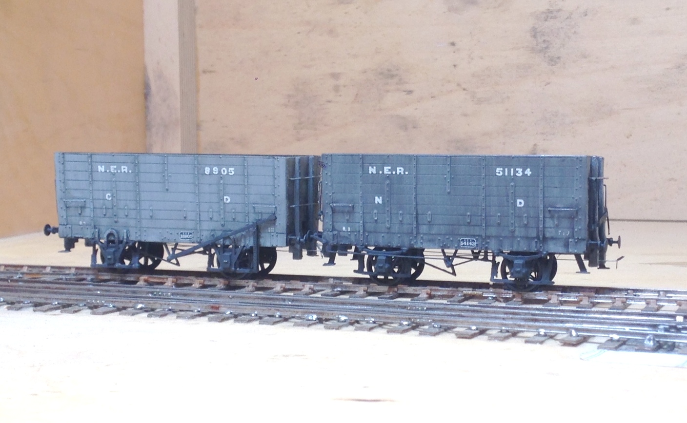
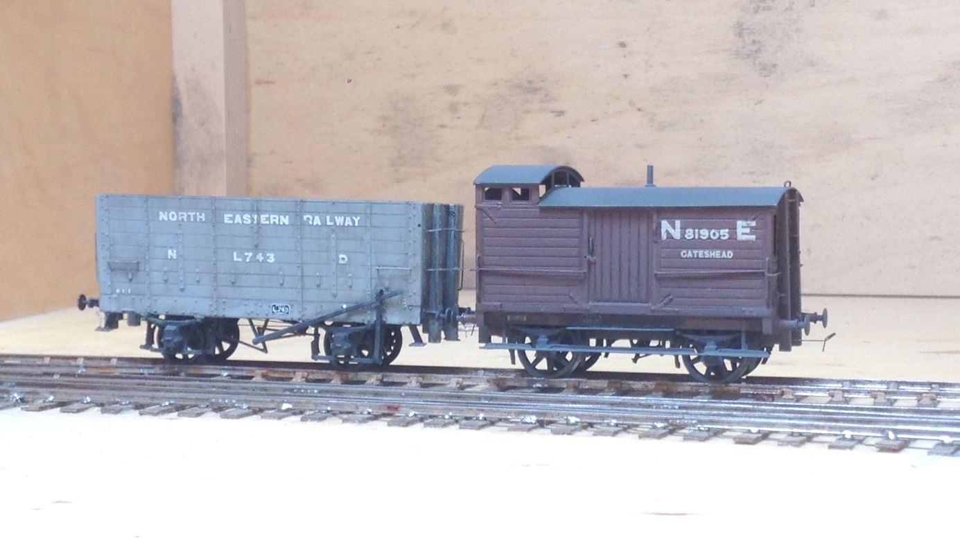
Finally, a group of wagons for Benfieldside. The hoppers have been seen before and the brake van we will hear more of another day.

Fastrack Finescale – Mousa Models Cast Resin Wagon Kits
I have been building a couple of Mousa Model‘s kits lately; which has been a bit of a tale of the good, the bad and the ugly. Whilst the bad one will be written about in due course, this is the good one! The remarkable thing about it is its ease and speed of construction – so much so, I timed its construction just to see how fast I could build and paint it. The prototype is a LNWR dia 32 covered goods van, with a door to one side only but also with a roof door. This is the tale of its construction:
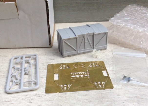
0hrs 1 min – Straight out of the box, the body & underframe are separate cast resin parts, as is the fret with the axleboxes, springs and brake gear. The underframe is an etch kit and the buffers are 3-D printed.
0hrs 15mins – The operational underframe has been folded up and fillets of solder run down the joints. Waisted top-hat bearings inserted in the bearing carriers along with the suspension springing wire. The first two carriers have been cleaned up and are inserted in the W-irons ready to receive the first wheel.
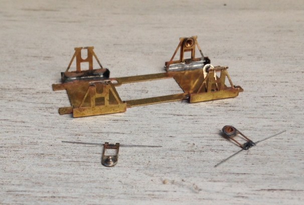
0hrs 25 mins – The remaining bearing carriers have now been fitted and the operational underframe has been stuck to the underside of the cosmetic underframe – wait 10 mins for the araldite to fully go off – so time for a cuppa!
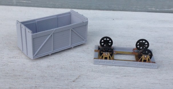
0hrs 45mins – the casting has been cleaned up to remove any casting burs/flash, which was apparent in small amounts around its base but actually the main casting was pretty good. The first two axlebox/spring assemblies fitted – but only after I opened up the rebate to their rear to ensure that the top hat bearings had room to slide and cleared away rather more flash. Being cast resin, the vehicles are pretty light so some weight has been added – 25g per axle is my rule of thumb. One thing I have found with vans is that the weight can detach so I tend to mechanically fix the weight too now, in this case with a couple of 8BA screws.
1hr 0mins – the second set of axle guards and springs now affixed, as is the body to the underframe. I decided that the bolt heads on the solebars were a bit too proud, so took them down a little with some wet and dry paper. A brake block has been attached – the kit provides a choice of timber brake blocks (for early periods) and cast iron – I went for the latter. I also decided, however, to cut away the brake lever as I felt it was both a bit too delicate to survive and also it was not quite straight. Instead, I provided a piece of 0.6mm brass rod to both help secure the brake block in place and to provide a mount for the replacement brake lever.
1hr 15mins – the buffer shanks have now been fitted (a tiny amount of fettling was required to the open the holes out slightly) and coupling hooks have been added. The kit does provide etched versions which I only failed to use as I thought I could save 5 minutes of the build by using Exactoscale hooks). A new brake lever and lever guard are etched brass from 51L models and should be more durable than the resin one provided in the kit.
Still 1 hr 15 mins – a piece of PCB has been provided for the eventual fitting of AJ couplings and I took advantage of this to provide a temporary bracket of metal to hold the model by during painting. A good scrub in warm soapy water, followed by a rinse and a second clean with a cream cleaner (washing up liquid leaves a residue, so I always do the final clean prior to painting with a cream cleaner) occurred next. So that is the model built in only an hour and a quarter, which is faster than anything I have built before – including converting r-t-r stock!
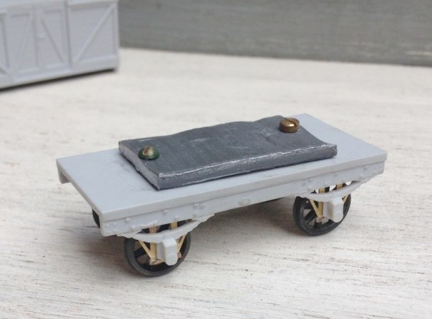
1hr 45mins – after masking the inside of the bearings, the whole model was painted in a mid grey – Tamiya TS 4 (German Grey). I thought this was about right for LNWR grey but as all greys of the time were lead based and thus darkened considerably over time, I tend to be quite cavalier about wagon greys! I did have a bit of an accident such that it ran on the roof but this was salvagable with a little bit of wet and dry once it had dried off. These paints finish to a semi gloss and thus are ideal for taking transfers, in this case HMRS Transfers sheet 16 in methfix because the vans were pretty archaic by the time that the grouping occurred, so I presumed that few would have been repainted in LMS livery.
2hr 15mins (but 10 mins of this was me correcting my messed up roof painting!) – ironwork below the solebar, the draw bar, buffer shanks and brake lever were all picked out in black. All then sealed with Testors dullcoat a couple of times.
So whats left? – I do need to weather it, some AJ’s need to be fitted and the “holding tab” will need to be removed. I am waiting to do a batch of weathering, so it will be a bit quicker; maybe 30 minutes for the vehicle. So I reckon this will be a complete, painted and weathered very good quality van or wagon on the 3 hour mark – well worth doing and no need to moan about when the r-t-r manufacturer is going to produce it!

Scrap Tank Test Build – Part 4; Beginning the Chassis
Putting aside the body for a while, to take a look at the chassis because it is necessary to mount the two together and it is not possible to close up some of the element of the body until this is sorted out.
As with the body, I am trying to take a moderately fresh approach to the chassis to make this a little easier to build than certainly most of the kits I am used to. In this regard, most of the kits for the Highland are quite traditional in their design and I readily admit that all but two of my ideas has been either all out pinched from other designers or at least significantly inspired by them. All I am trying to do is use more of these neat ideas in a single kit to make the life of the builder easier. I am, however, finding that it makes my life more difficult, as there are a lot more moving parts to most components, so more places for the tolerances to be catered for; so as John Price has already said, the list of little tweeks and amendments to make is growing! At least, no one can say this particular kit designer has not built their own model.
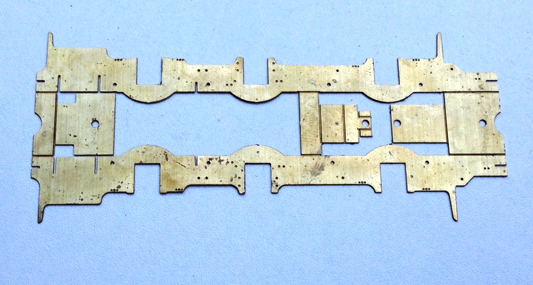
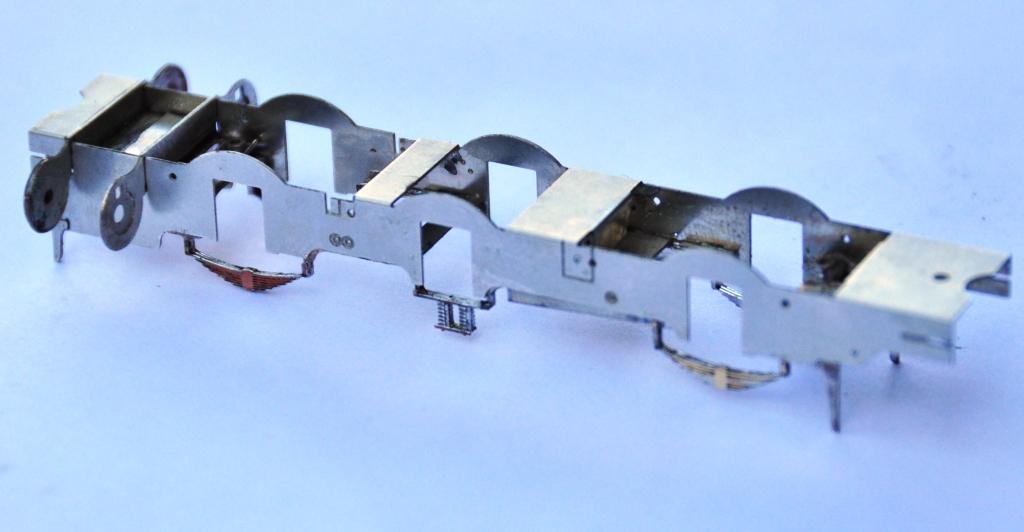
Anyway, this is what the chassis looks like in the flat; note that it is a fold up design – this is inspired by the Mousa Models chassis, so a pinched idea!
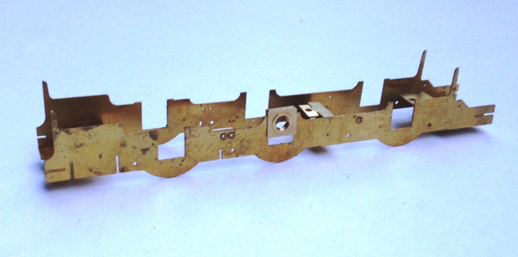
And this is what it looks like with the basic folds made up. What it achieves is really neat, as it is instantly sufficiently stiff to work as a chassis; by the time a couple of further cross braces have been installed the basic chassis is more than robust enough for its life.
My design uses the same slide in hornblocks as utilised by Comet and Brassmasters for their chassis. After a tiny bit of practise, it is possible to size the hole for the hornguides such that these are just too small when etched. This means that with a few strokes of a light cut file on each side, the hornblock becomes a tight sliding fit. Once all of the hornblocks are in, it is then possible to measure the distance between each on both sides of the chassis and also on the corresponding coupling rod. This is done with digital callipers and by the expediency of measuring the distance at its maximum with the callipers facing outwards and then repeating with them facing inwards the average being the actual distance between the centres. I reckon to be able to measure down to 2 or 3 hundredths of a mm, which is rather better than I can build to! Where there are inconsistences, this is dealt with by a few more strokes of the file on the side which needs to be adjusted to change the centre. This needs to be done anyway to turn the tight sliding fit to a snug but smooth fit for the hornblocks to work properly soif the centre does not need to be changed, the file strokes are undertaken equally on both sides of the hornguides.
This does need to be done after the coupling rods have been formed, of which we will see in the next posting. However, the chassis is also designed with a keeper plate to accommodate all of the cosmetic springing to the model and the ashpan sides. This is secured with a series of 12BA screws to enable it to be removed to allow the wheels/axles to be dropped out. A great boon as the model is built and painted.
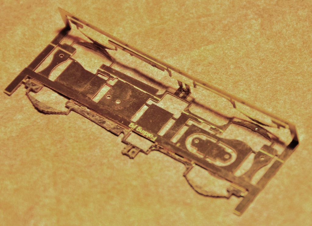
To make the assembly of this element easier (in fact in this case a lot easier!) I have created a jig that holds the two layers of the laminate in exactly the right position. The jig is chunky enough to avoid distortion as it is folded up and it locates the parts perfectly. In this particular case, the soldering needs to be done with care as there are folds to make after the jig is cut away and it is important not to fill this with solder before hand.
And this is what the keeper plate looks like – it is pretty delicate until it is mounted but fine thereafter.
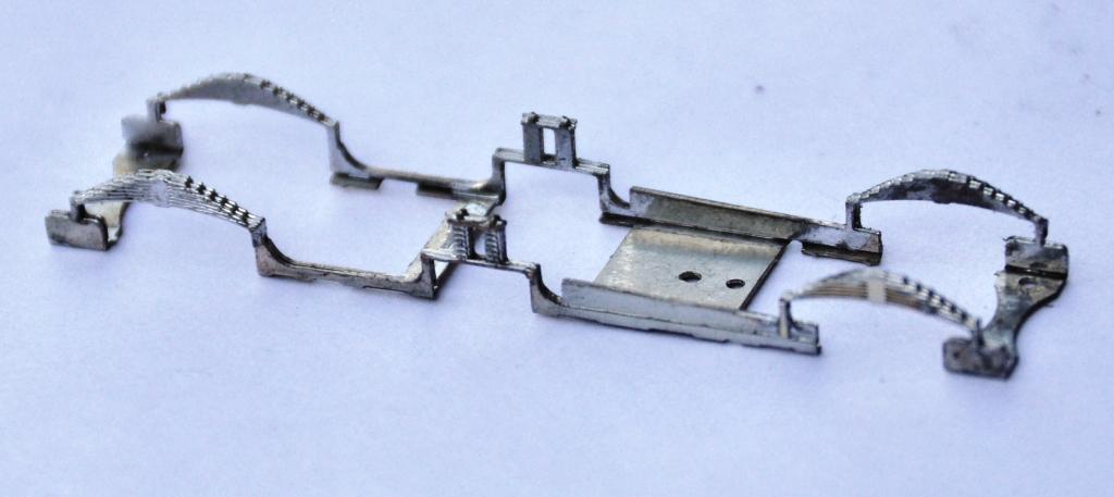
And the two components assembled look like this. The beginnings of the cylinders are also visible, this is a slide in module that can be removed for assembly and painting (although the scrap tanks were painted fairly simply, so this is not really relevant on this model).
Christmas is the season for…………. jolly well finishing stuff off!
Over the break, I have been concentrating on trying to finish things. Like many people, I find it much easier to start a kit or project than it is to get it fully finished. Indeed, do we every truly finish our models – certainly not our layouts!
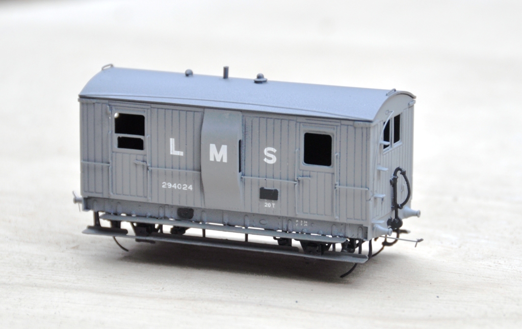
Back in March 2013, I completed a dia 39 goods break. These were the final Highland Railway break vans and it is not clear that they were actually finished prior to the end of the HR era. Given that I model in the mid 1920’s, I am quite content to do this in LMS grey which to date I have not seen the model depicted in! The main body painting has been completed and the van has been lettered but weathering, the interior and final detailing/glazing is still to be completed. Based on the Lochgorm Models kit with minimal adjustments (a few pipes below the chassis and sprung W irons in lieu of the compensation provided in the kit) this is what it presently looks like:
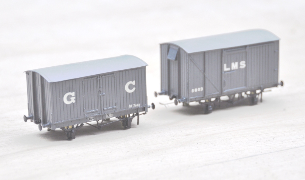
Also coming through the paint shops are a pair of vans. The first is a Great Central van build from a Mousa Models etched brass kit and the other is a LMS early standard van from an injection plastic moulded kit from Cambrian Models. Both are pretty simple models to build; the Mousa Models one was built as designed and no adjustments were found to be necessary. I only fitted springing to the Cambrian one and got rid of the rather too thick W irons in the process. Again the bulk of the painting is complete, but some dirtying work is definitely still required.
Apologies for the slightly squiffy photos; I left it a bit late in the day to take them and the light was poor. I have made a lot of progress painting the NER hoppers, but the photos of these really did not make it and need to be repeated. Something to post tomorrow I suspect!
