Blog Archives
The Colour Red – or the Quest for LMS Crimson Lake
A topic that comes around from time to time, including to my lips, is what colour exactly is Crimson Lake? I thought that my analysis and that of others that have contributed to the discussions were worth sharing more widely; so here goes……….
The Historical Context
The first good insight I have is from George Dow who was a prolific author of the 1960s and 1970s, including on liveries who wrote in the Railway Modeller in 1973:
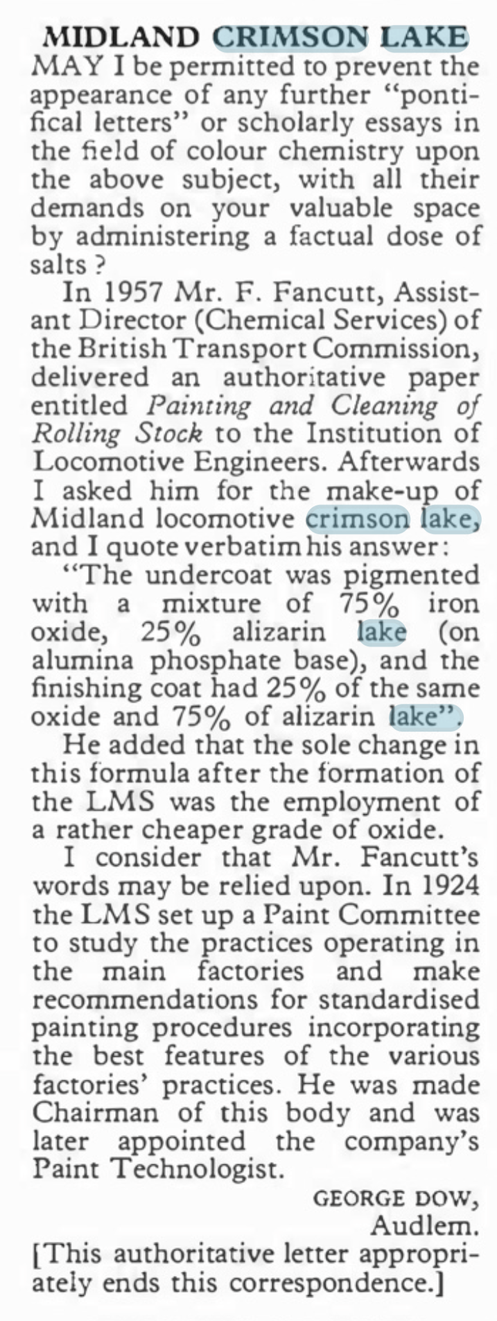
However authorative this is, fifty years later, with the change from natural to synthetic pigments this is not of great help. Also B&Q do not stock alizarin lake last time I looked as it is a pigment produced from a complicated processing of a vegetable and is probably fairly inconsistant anyway. https://www.winsornewton.com/row/articles/colours/spotlight-on-ruby-madder-alizarin/).
The Problem With Reds
Many years ago, when I was still in my shorts, I worked in a printing ink manufacturering business and red was one of our bugbears. This was for three reasons; as a colour it is less opaque than many colours so were prone to poor coverage, it is also prone to fading and like all paints, it is affected by the surface treatments, in our case varnishes. All of these issues affect how Crimson Lake appears on both the prototype and our models.
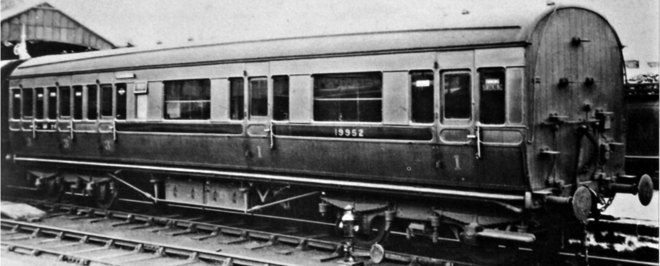
A Caledonian diagram 106 non-corridor composite shortly after being renumbered to 19952. This appears to have been acheived by painting over the predecessor number and then the application of the fresh number and then varnishing. The patches that have been so treated stare at you somewhat and ilustrate how the paint and lustre deteriorate! Photo by H.R. Norman ref 6081 and now in the NRM
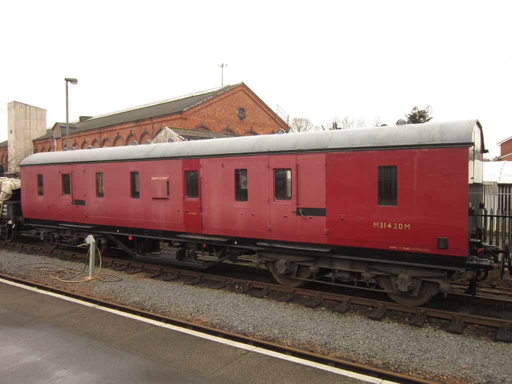
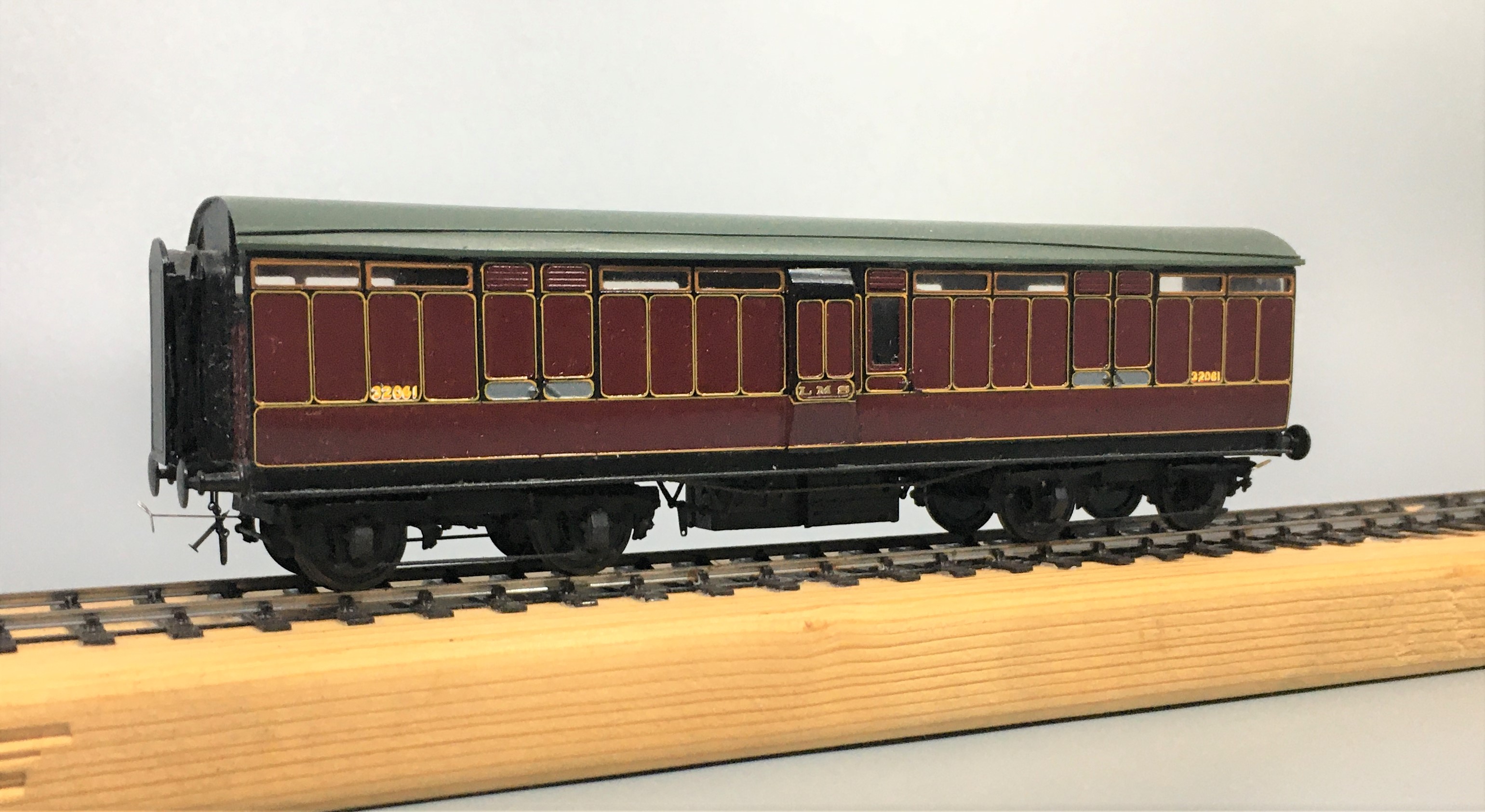
Its still a problem now too as this diagram 2171 full brake at Kidderminister shows. Photo SVR Enthusiast via Flickr
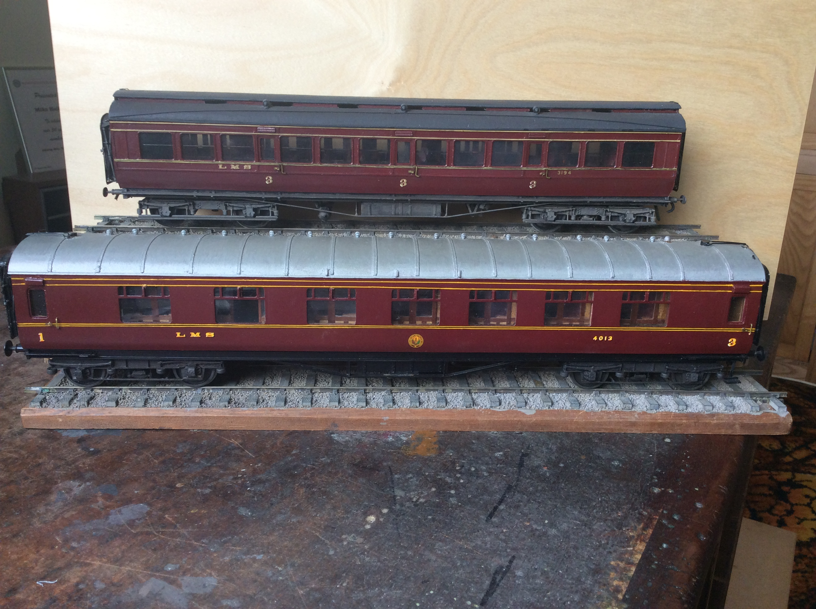
Both of these coaches have been painted in the same top coat, Precision Paints LMS Crimson Lake. The top coach, the clerstorey, followed the paint sequence noted by George Dow above – a first undercoat of LMS wagon grey, followed in turn by 75% grey, 25% crimson; 50% each; 25% grey, 75% crimson and finally 100% crimson. On the lower coach, the crimson was neat and painted over an undercoat of LNER bauxite. Both were painted at the same time, in otherwise the same manner and in both cases they were varnished but not weathered. The difference is startling! Photo and models by John Hastings Thompson.
Does Colour Scale
Like weight, I am not convinced that colour scales or perhaps it does but given that our models are smaller than the prototype it is more heavily heavily by contrast. I am sure we all know about the optical illusion causing the viewer to read differnt colours of the same sample by virtue of the background – is this happening to us as we perceive the colour of a model? Try the sampel from the Exploratoium below:
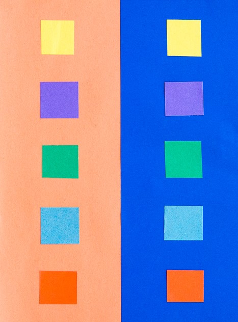
The presence of lining is also a major influence of the feel of the colour. The gold and black of the LMS seems to add a bit of sparkle and depth of colour to the red.
It was a Long Time Ago
We must also remember that the last LMS crimson lake locomotive or coach will have been repainted seventy years ago and even the last BR maroon loco was withdrawn sixty years ago (plus there is the argument as to whether they realy were the same colour as well!). Whose memory of colour is good enough to survive this long? Even photographs from this era as a whole cannot be relied upon due to the variability of colour rendition, the nature of the light that the subject was recorded in or the level of contrast with its surrounding – none of these issues have gone away with modern digital photographs!
I for one have never seen either original colour and my view of what crimson lake is being based on the preserved locomotives that I have seen over my life. Have the preservationist got it right? Maybe they are better informed than you or but if this was true, why is there so much variation in the colour from the ready to run manufacturers or even the paint manufactuers?
However, whether they are right or not, the preservation scene has set my expectation of what the right colour is and I suspect the same would be true for all of us. Whilst I hate making modelling decisions on any history which is not real, I have reached the conclusion that the right colour for me is one that matches what I have seen in the UK preservation scene.
Where does this leave us?
Possibly the first conclusion is that there are a wide variety of reds that we can safely consider to be correct for Crimson Lake – phew, because when I look at my models I do have variences!
The second conclusion is not only is some inconsistancy acceptable, it is actually essential because red faded so noticeably. I am less convinced that the changing of hues seen across some colours but a toning down of the colour and tinging to a more matt colour is definitely prototypical.
In my personal quest for a colour I have been through multiple agonies to get the right colour. Thirty years ago, it was Precision Paints Crimson Lake but this seemed (to me anyway) change and become too purple over time. I then used Rover Damesk Red from a rattle can but found this too uncontrolable or, if I held it further from the model prone to to giving the orange peel effect. I was then put on to the solution to all our colour problems by Jim Smellie (of Caley Coaches).
This suggestion was to use the colour that the preservation industry generally use to source paint for the 12 inch to the foot models. This comes from Craftsmaster paint who have a series of specialist railway colours for most of the colours that we will wish to use. I use a numberof their colours including Crimson Lake. I have yet to adulterate this but i do intend to let it down with some white to imitate fading – hopefully this will not send me down another quest for the right faded Crimson Lake!
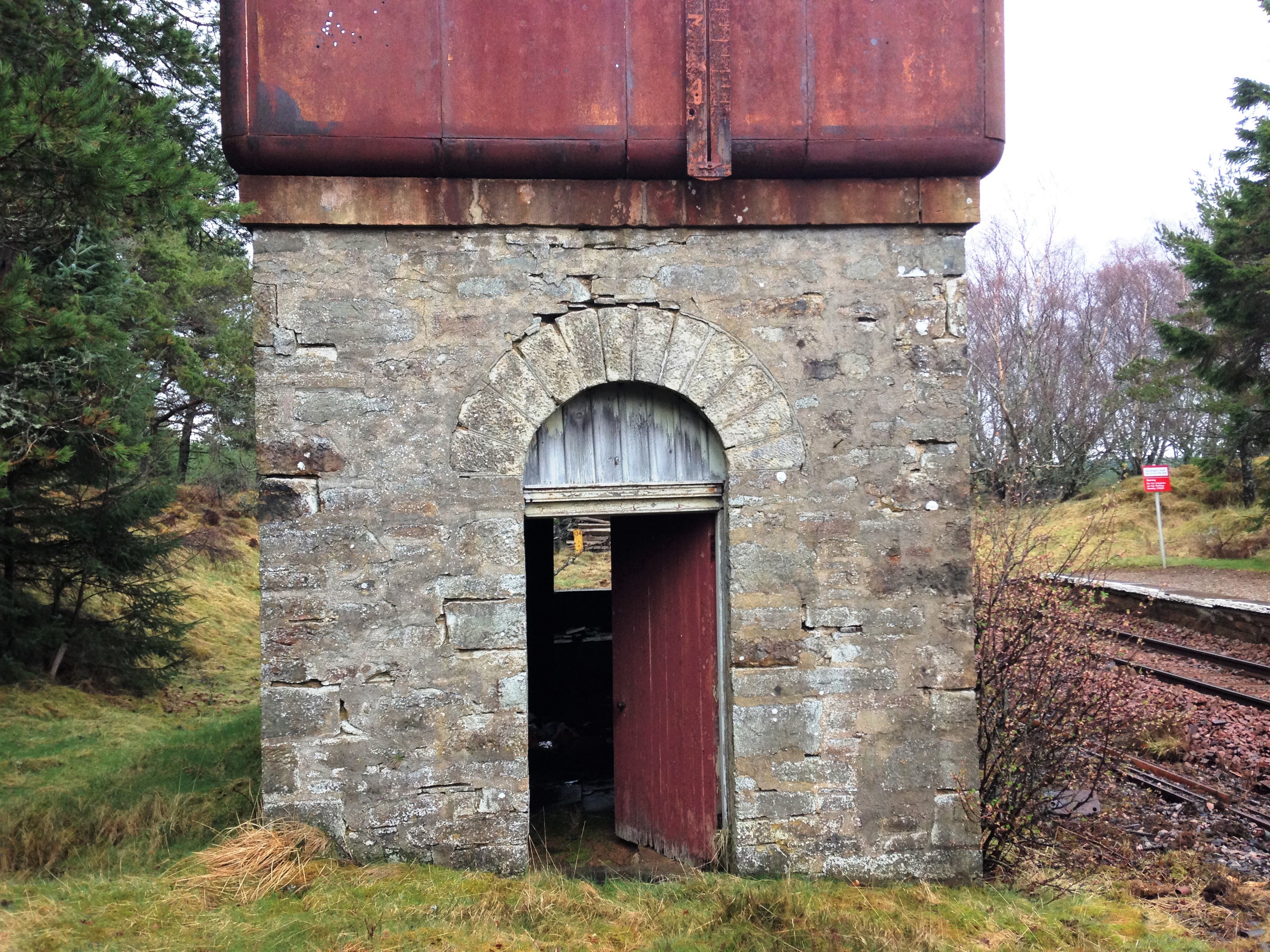
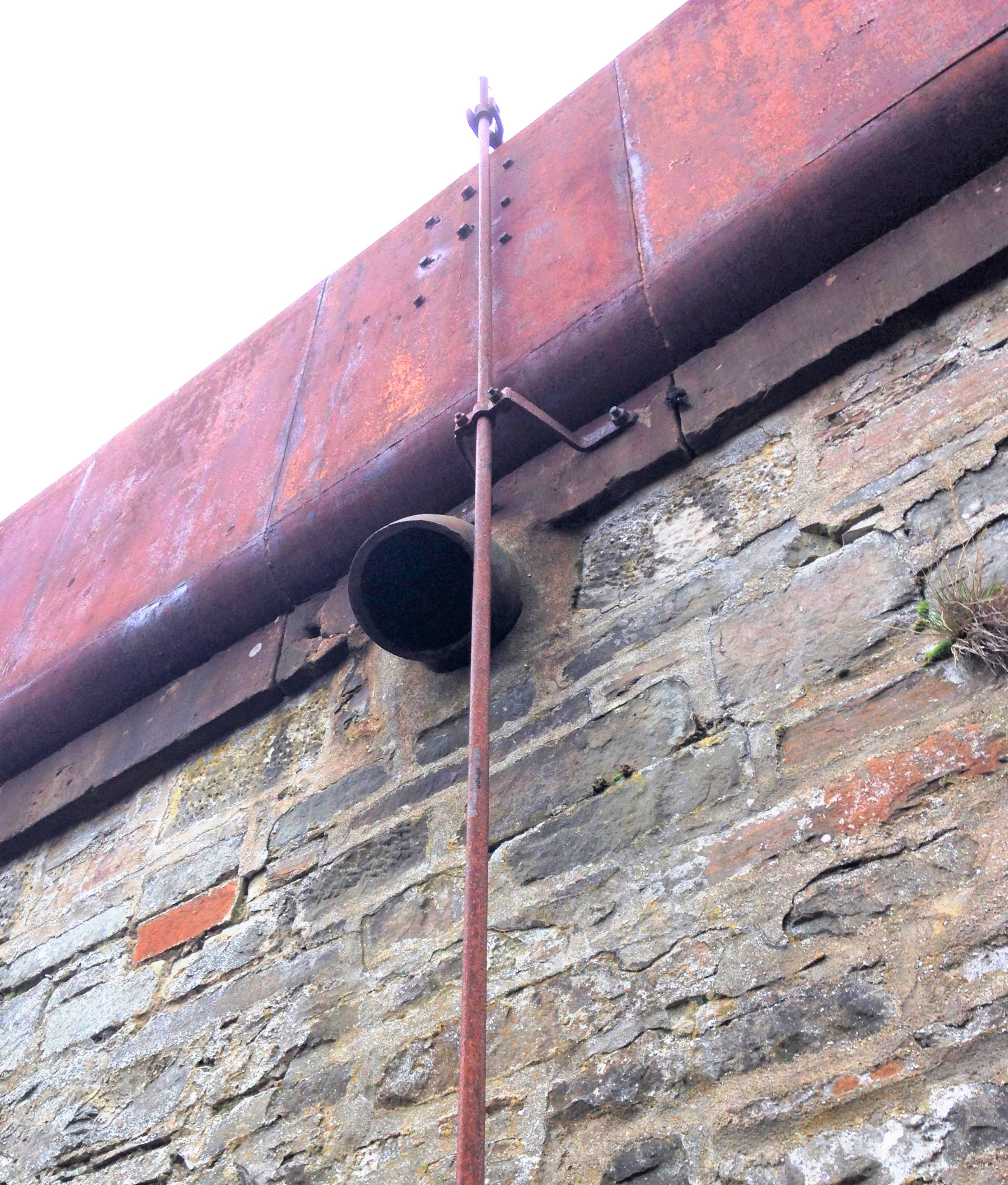
Alnabreac Water Tower – the Prototype
The smaller of the two water towers I am building is a model of the tower that the Highland Railway built at Altnabreac. Altnabreac is around 12 miles from the nearest paved road so even though it has not been used for approaching 60 years, it has proved too expensive to realise its scrap vale.
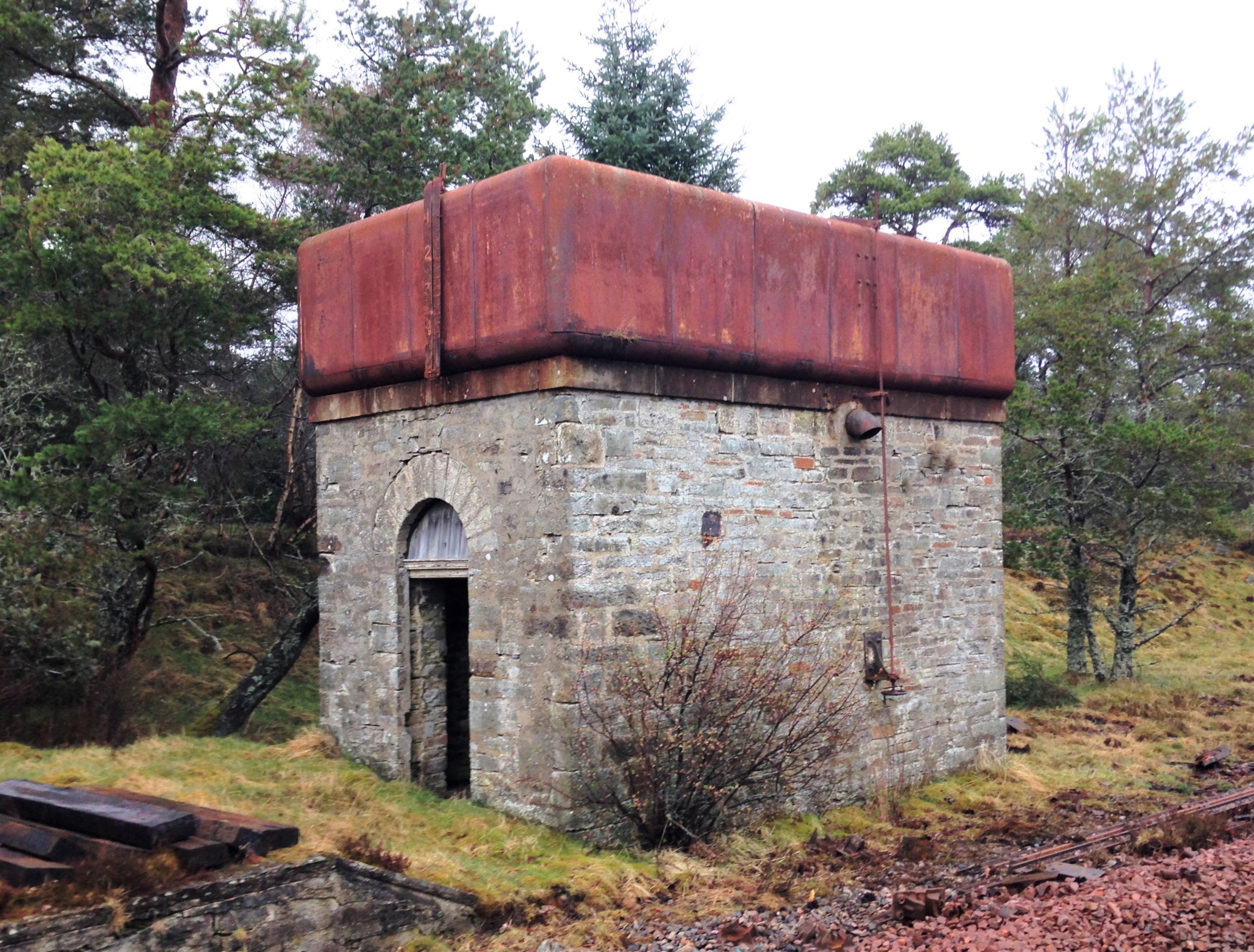
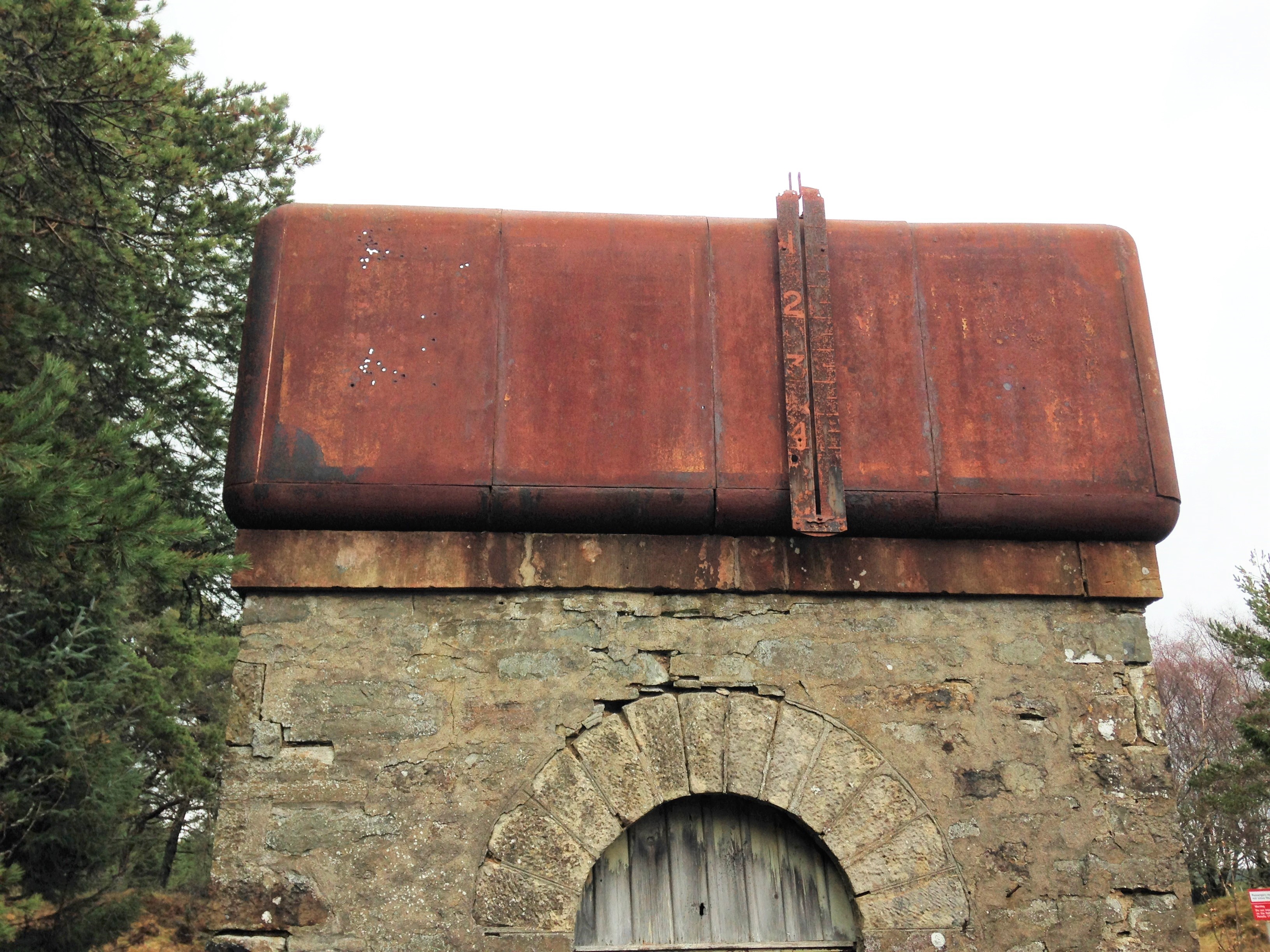
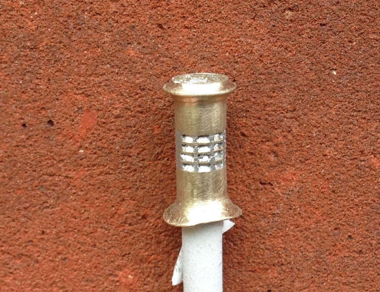
What is possibly even more remarkable, you can see the paint – including the detailing at the corners – which probably dates from the LMS era; how much original pre-1948 paint is still out there?
Being able to get up close to the tank, it can be seen that it is made out of sections; there are quarter segments for the corners and then straight panels for the sides. They obviously came as a kit of parts and could be built to a size to suit the requirement. Thus, I note that the Altnabreac is the same width wide as the Kyle tank was deep – so I can determine how many panels were used to make the Kyle version. Whilst the lines are fient, they are there and I will replicate them with a hint of a score on the plasticard.
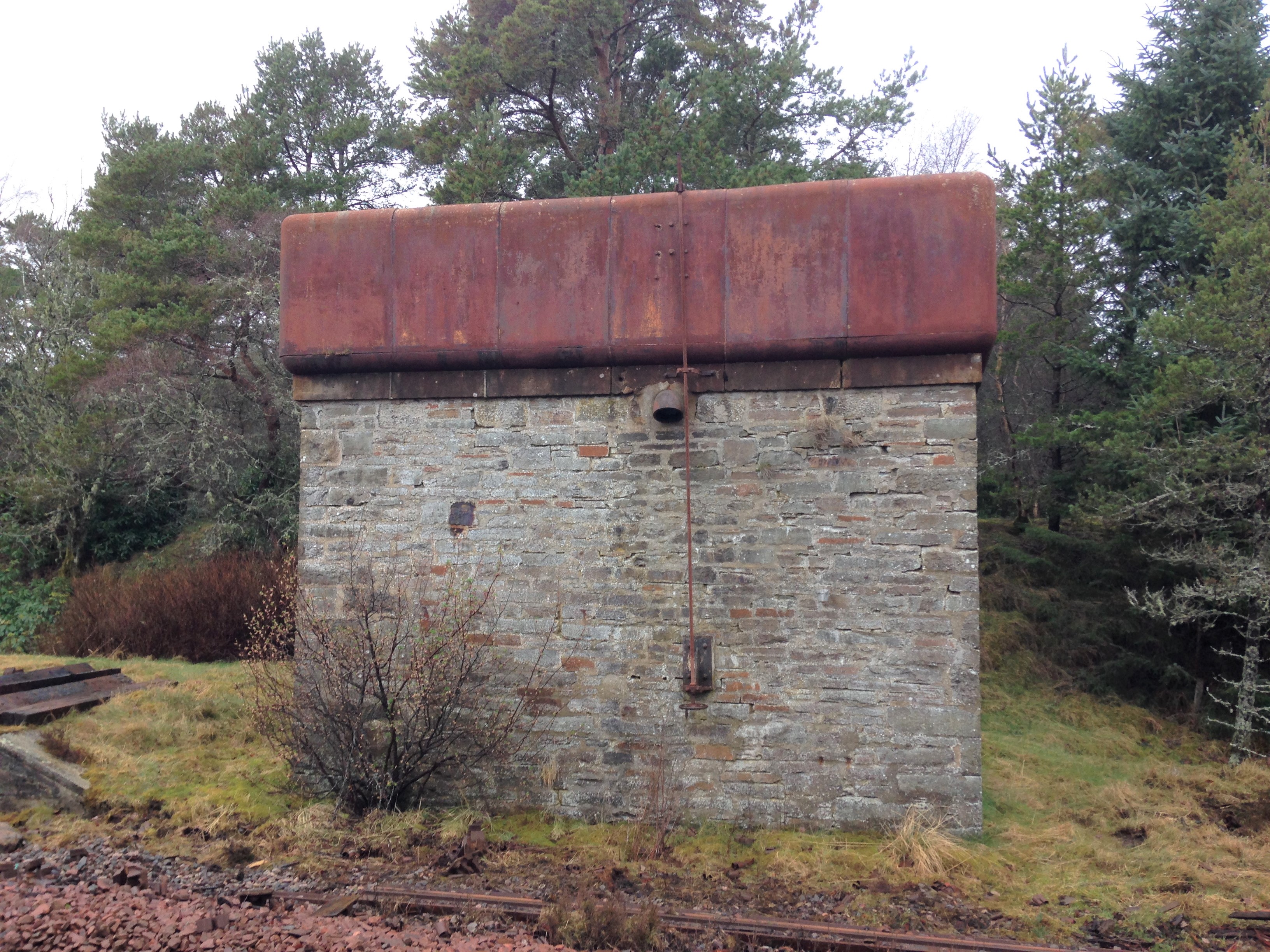
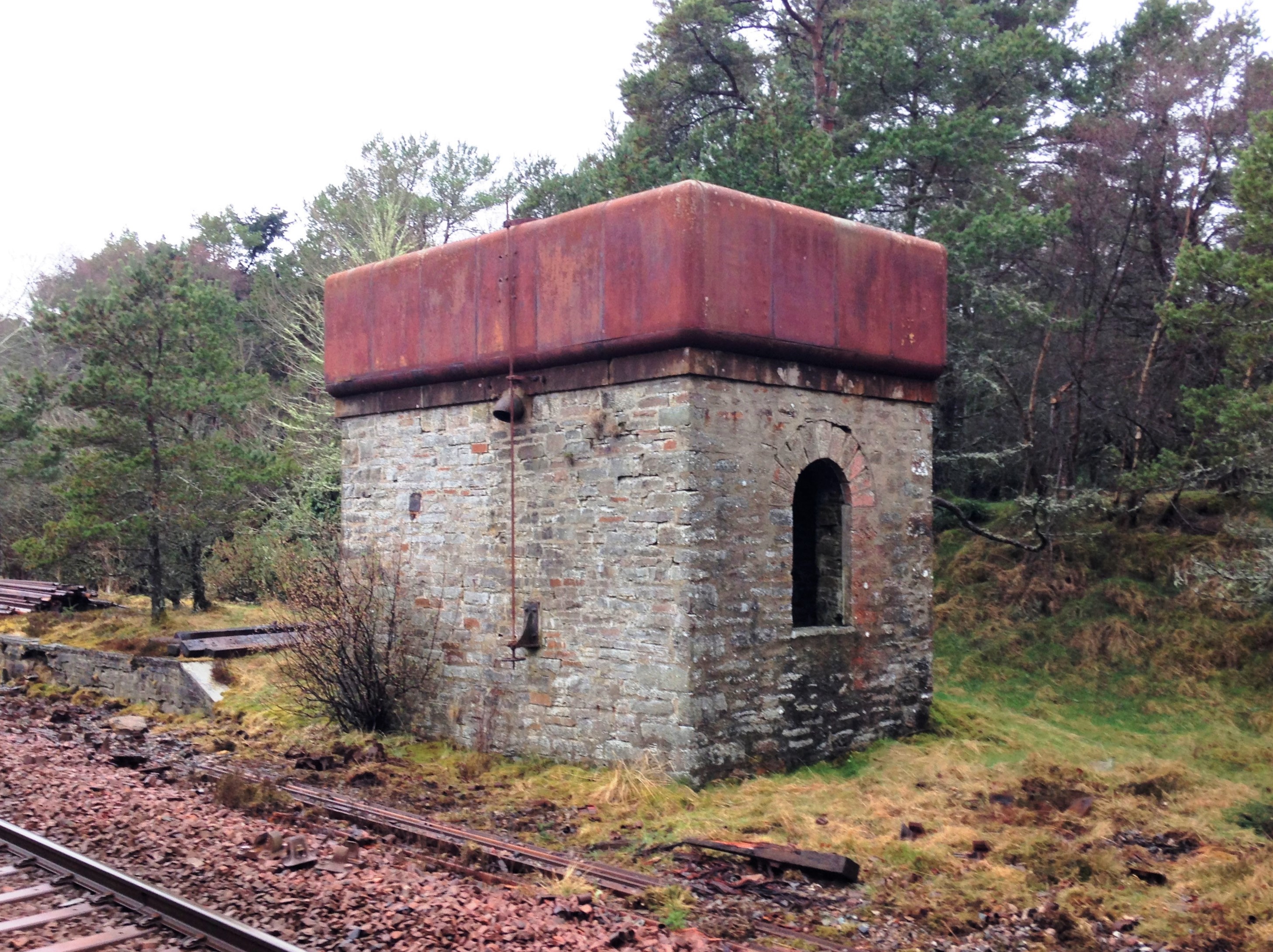
A float inside the tank was used to transmit the water level to this gauge on the exterior.
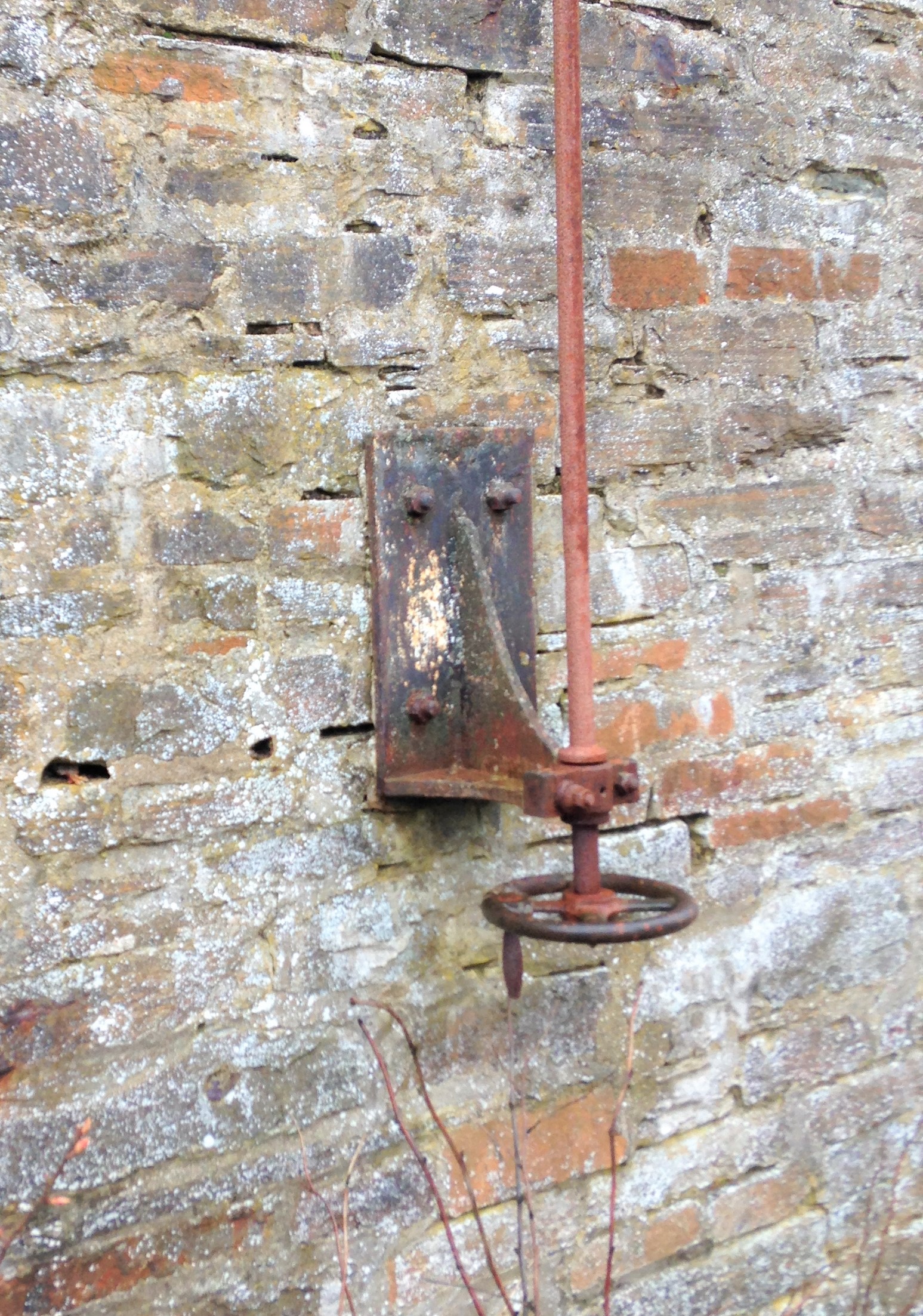
The tank as a whole is remarkably intact – the only elements I can positively identify is missing is the delivery bag which will have been of hessian and the wooden windows. However, I suspect there are two other elements that have now been removed. There was probably an access ladder at one end to reach the interior of the tank but leaving it in situ would to be dangerous, hence its removal. Furthermore, there is no sign of any heating to the tank. Whilst the largish body of water will have taken a while to freeze, the region around Altnabreac is well-known for its cold temperatures so I suspect there is a boiler inside with a flue through the tank. The outlet valve is controlled by a wheel at low level connected with a rod with a thread at its head. This connects to one end of a lever that has a threaded nut in order to transfer the movement into the interior of the tank where the valve is located.
A drawing of the water tank can be found at this link: Altnabreac Water Tower or if you are a member of the Highland Railway Society it will be in the next Journal and subsequently from their drawing service.
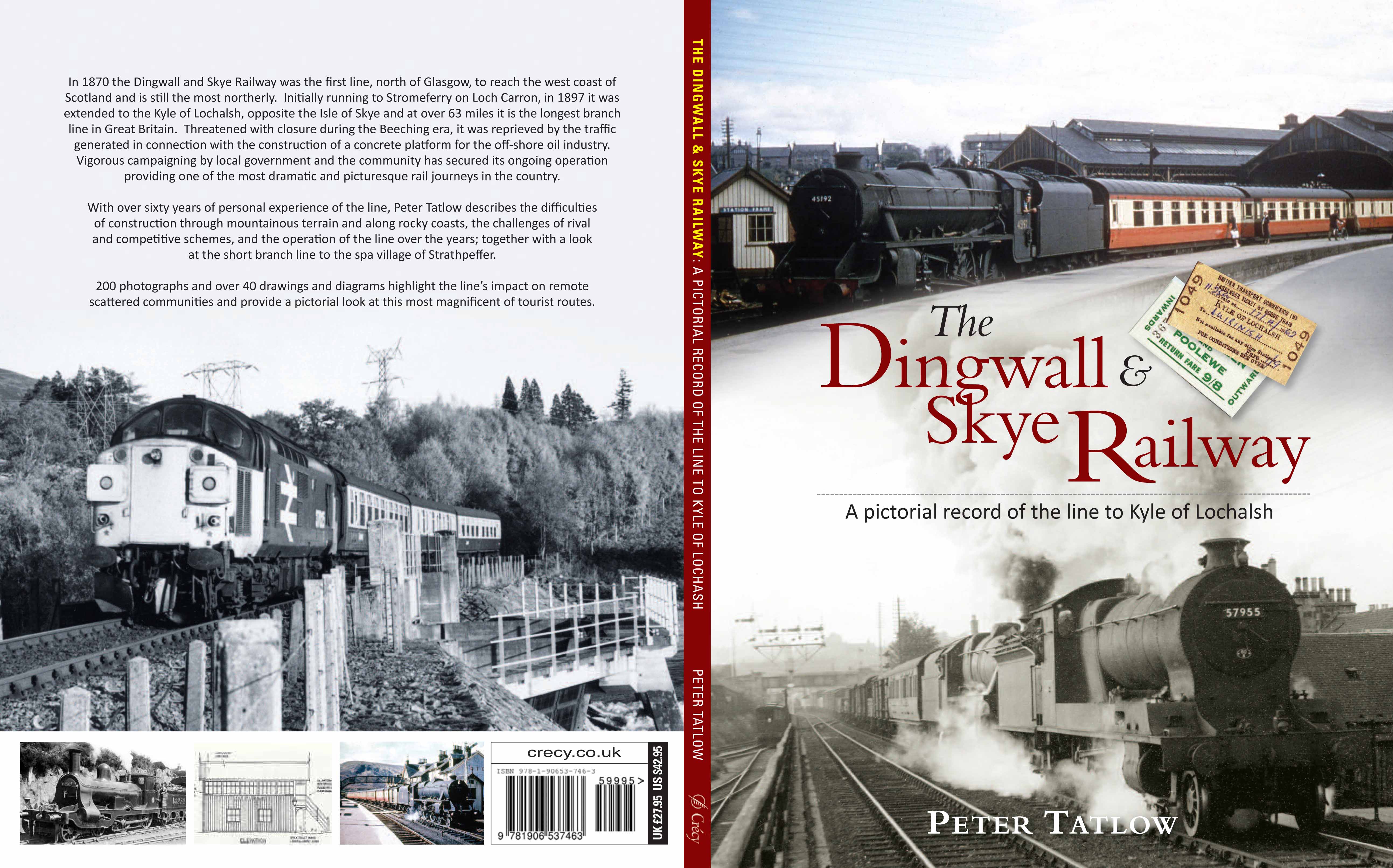
The other water tank I am building is a model of Kyle of Lochalsh’s water tank. Eddie Bellis drew this and his drawing is in the November 1975 edition of the Railway Modeller. There are couple of pictures of in LMS Engine Sheds: Volume 6 by the Oxford Publishing Co. The only other Highland Railway water tower that has been drawn that I know of is Garves, which Henry Orbach drew – it is in a 1950s Model Railway Constructor or was reprinted in my fathers The Dingwall & Skye Railway.

Catching up on a Tennant
Way back in the mist of time (well 2016), I made a start on one of Arthur Kimber’s kits for a NER 2-4-0; termed a Tennant. After residing at the back of the cupboard for a bit too long (as is the way with my modelling, I do admire those that start something, see it neatly through to a finish before starting another……..!), I have made some more progress with it.
First up with the tender body which is close to finished except for some detailing around its front.
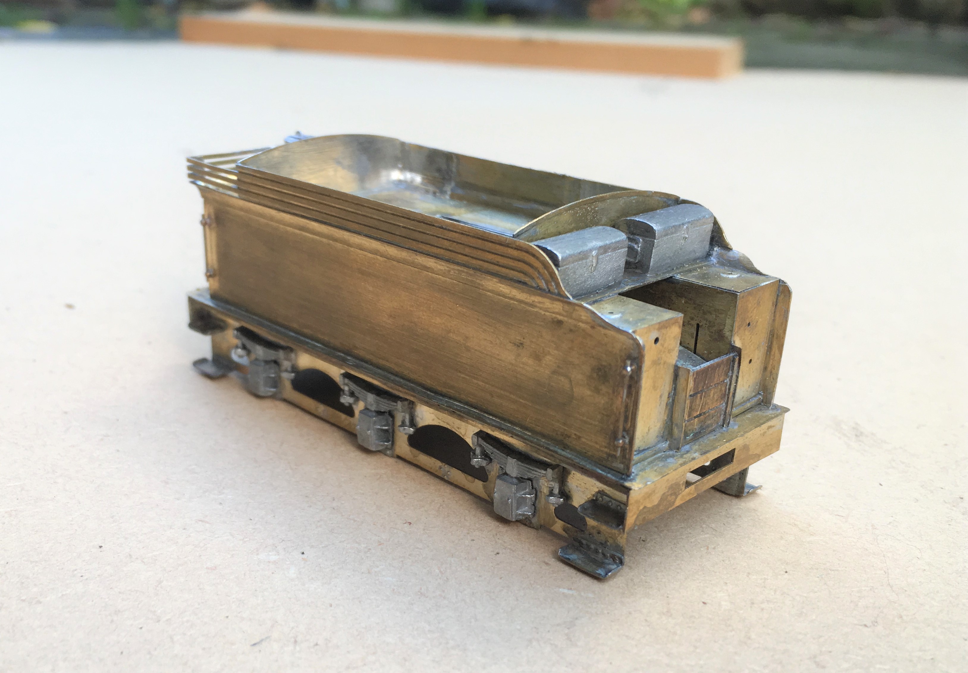
There was a bit of irritation in the building of this; despite being quite a modern kit the rear panel was much to narrow, the buffer beam a bit flimsy and there were some missing details around the front of the tender. Nothing someone raised on Jidenco’s kits can’t sort, but I rather hoped it wouldn’t happen with a modern design!
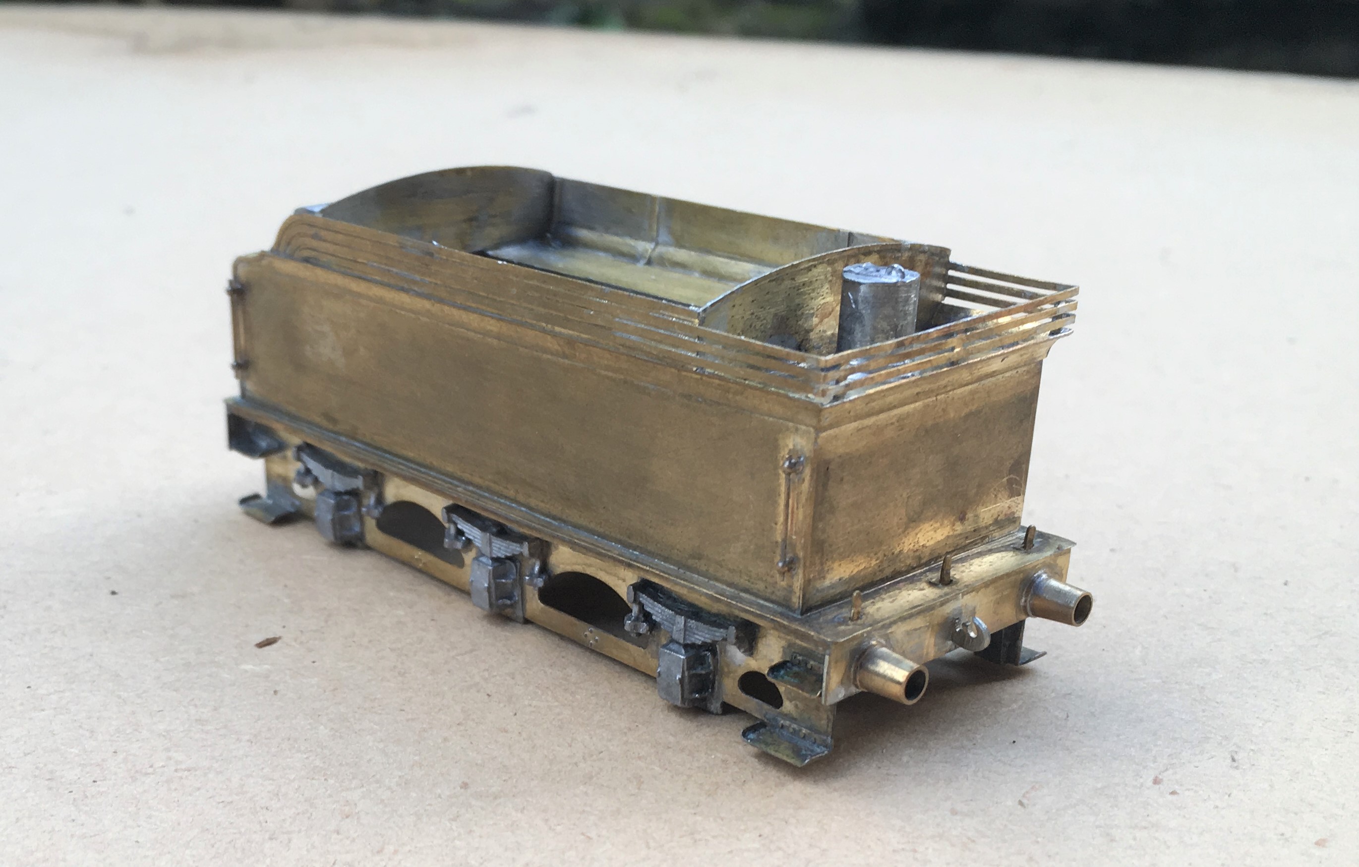
I also found that the boiler was about 0.7mm too long; a degree of filing and fettling has got it fitted. It is fair to say whilst there were these niggles, most of the rest of the kit is well designed and there are a number of neat facets to the kit, the flairs to the tender top for example are pre-rolled and they are very difficult to form without the right presses.
Here she is with the boiler now fitted and the first of the boiler fittings being attached. Something that grates with me on many people’s models is where these do not sit down tightly on the boiler or have overly thick flanges onto the boiler. Given that these are castings, it is understandable that these sometimes happen but they do damage the reality of the model and it pays to address these issues. For this reason, I prefer to solder them in place and am prepared to attack them with a file both before and after they have been fitted.
This does create a problem of soldering the parts in place; they are quite chunky so need a lot of heat to solder them in place and it is difficult to move them about to get them in the right place when they are so hot. I have just started to address this by drilling out the base of the boiler fitting and tapping it to take a 10BA bolt + washer. This allows the the fitting to be moved about until it is in the right place and held tight with the bolt so that it can then be soldered. I am pleased with this little trick; it definitely repays the effort and for the white metal castings, saves the risk of returning them to a blob of metal with too much heat!
One example of a Tennant is preserved, being situated at the Head of Steam Museum at North Road Darlington Station. This has enabled me to take a good number of detailed shots but they are all rather close up they don’t really capture the prototype; so here is one from Neil Dimmer’s collection from the earlish 1920s, at (I think) York. The thin nature of the flanges to the dome and chimney I comment on above can be seen in this.
![[IMG]](https://photos.smugmug.com/LNERSteam/1884-NER-Henry-Tennant/Tennant-E5-NER-1463-2-4-0-Locomotives/i-L5bsMX9/1/794c2272/XL/1463%20Tennant%20E5%20%28NER%20%271463%27%29%202-4-0%20Locomotives-XL.jpg)
This view also illustrates how thin the boiler bands are. Given that this will be painted in NER livery that has lining on the boiler bands I am going to rely on the thickness of the lining transfer to give the impression of the boiler band rather than represent them in metal.

Making Louvered Chimneys
One of the most characteristic features of the Highland Railway’s locomotives for many years was the louvered chimney. This was fitted to almost all of David Jones’ locomotives and although some lost them over their lives, most retained them until withdrawal. Indeed this style of chimney can still be seen on the preserved Jones Goods which is presently in the Riverside Museum of Transport in Glasgow.
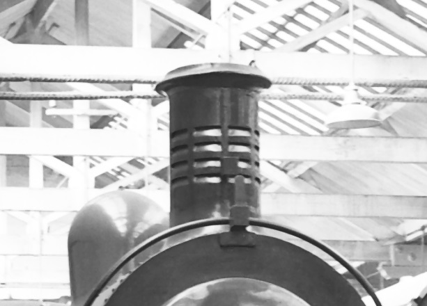
There is debate as to the reason that these chimneys were fitted but it is generally considered that they sought to assist in the drafting of the fire on the downhill sections of the line. There were many long descents on the line and regulator would be closed for such descents and thus the fire was not drafted by the exhaust from the cylinders. The louvres would have allowed the passing air to pull on the fire to keep .
Clearly for such a characteristic feature of the line, it is important to model it well on my locos but I am not totally happy with the renditions that are available. The whitemetal chimneys look too chunky and neither the cast brass (Lochgorm) or turned brass (Jidenco/Falcon Brass) have very distinct louvres. I feel that they can be improved and this is how I go about doing so; in this case starting with the Lochgorm Models cast brass chimney. Similarly, if you are turning your own chimney, the same situation arises,
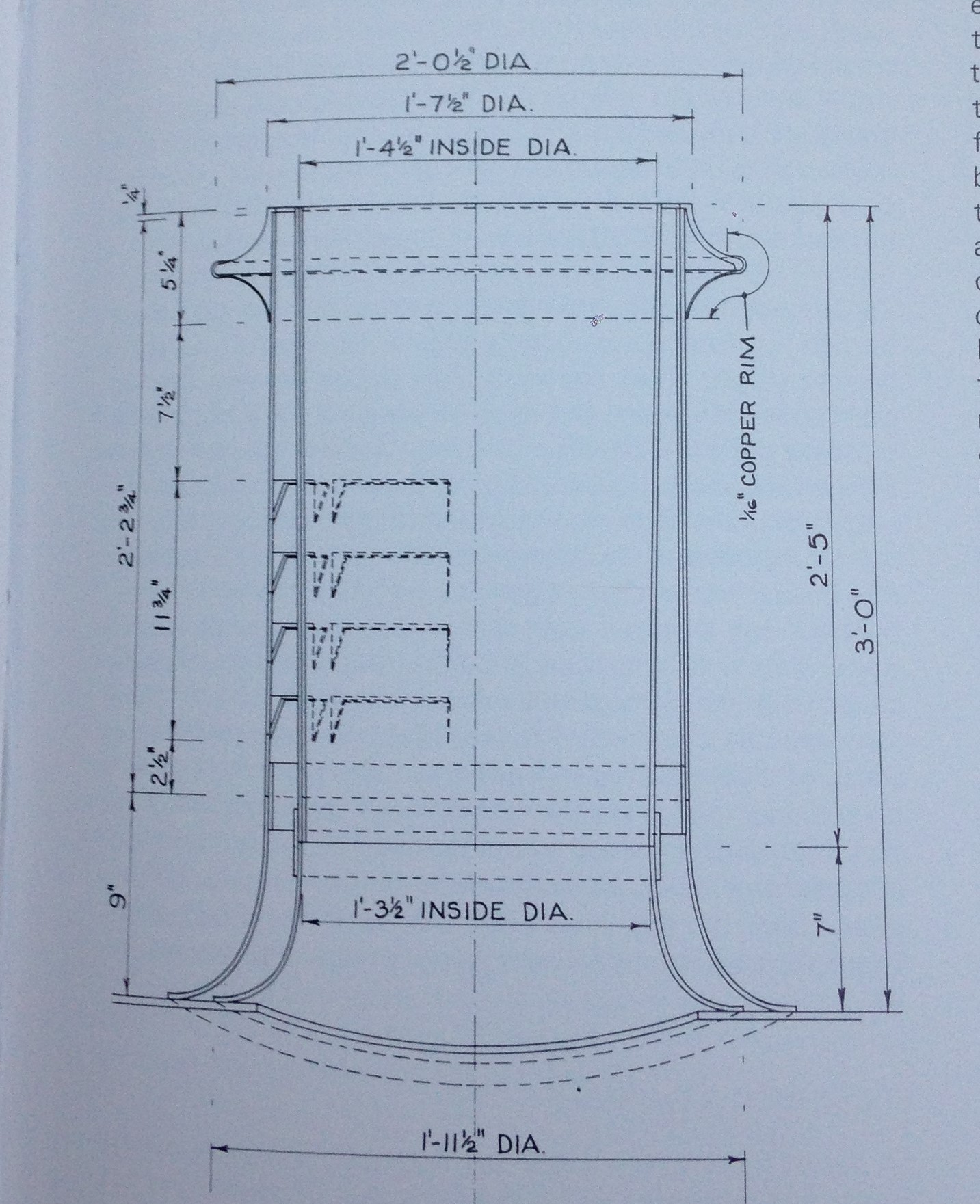
I started by some basic improvements to the chimney. I found that my casting was not parallel down the shaft of the chimney, being fatter at the top, and also not particularly smooth. I therefore turned it down a little on a drill with some needle files. The casting sprue was not particularly central so to be able to turn the chimney it was first necessary to file this to get it more central. Thereafter, I drilled out the chimney to 4.5mm diameter to its full depth on a pillar drill. I am doing this partly for appearance but really because I intend to put sound speakers in the smokebox and it is necessary to leave routes for the sound to escape – the most authentic being to chimney! Casting brass is very hard and this is no little task – it takes some time, lubricant and anyone in the house need to be able to tolerate a good amount of noise!
The Lochgorm Models cast chimney has a series of depressions to represent the louvres and these are what I felt needed improving. I started this with a piercing saw with a fine (OOOO) slot at the top of the cast depressions. This is cut across the whole width of the depressions and a little further beyond, ignoring where the pillars between the slots are.
These are then given a chamfer slope with a needle file that has a blank face (to make sure it does not cut above the slot). This also needs to be taken beyond either end of the intended louvres to avoid the impact of any taper. The top three have been formed in the picture below, with the lowest still just the piercing saw cut.
Once all have been formed, the next task is to undo all of the work by filling them in again! All of the gaps are flooded with solder. I used 145 solder as it would survive the reasonable temperatures that would be incurred in soldering it to the boiler but also be soft enough to carve out again.
The louvres were then marked out, starting with the two vertical rows either side of the central pillar that must match the highest point of the flare. Then with a knife, the solder infill between these is cut back out. The knife can cut through the solder to cut it out but does it will not affect the brass, so the louvre is reformed. I found that the technique was to initially cut it away and once a basic amount was removed the blade can be scraped side to side within the louvre to get a smooth surface. This brings up burrs of solder at either side of the louvre which are then cut out. This is what it looks like with the first two columns of louvres done – I found it best to do it like this as it was easier to get them vertical than by doing them in rows.
You will find that you get through a fair few blades doing this as the most challenging part is getting the corners crisp (and the photography is very cruel in this regard!). It is also easy to be a bit enthusiastic and accidentally cut pillar – if this happens, it can be reformed with a dab of solder and the process repeated until there is a neat row of four slots in four columns.
Once you are near to finished, a dusting of grey primer shows up any remaining inconsistencies and hopefully it looks something like this:.
This process creates not only the slope of the louvre opening but also the dark shadow of the cavity. In my view these features are necessary to capture the feel of the distinctive feature of the Highland Railway. It takes around 2-3 hours to make each chimney and in I reckon it is worth the time and effort.

A Promise is a Promise
Dad coming good with a promise…
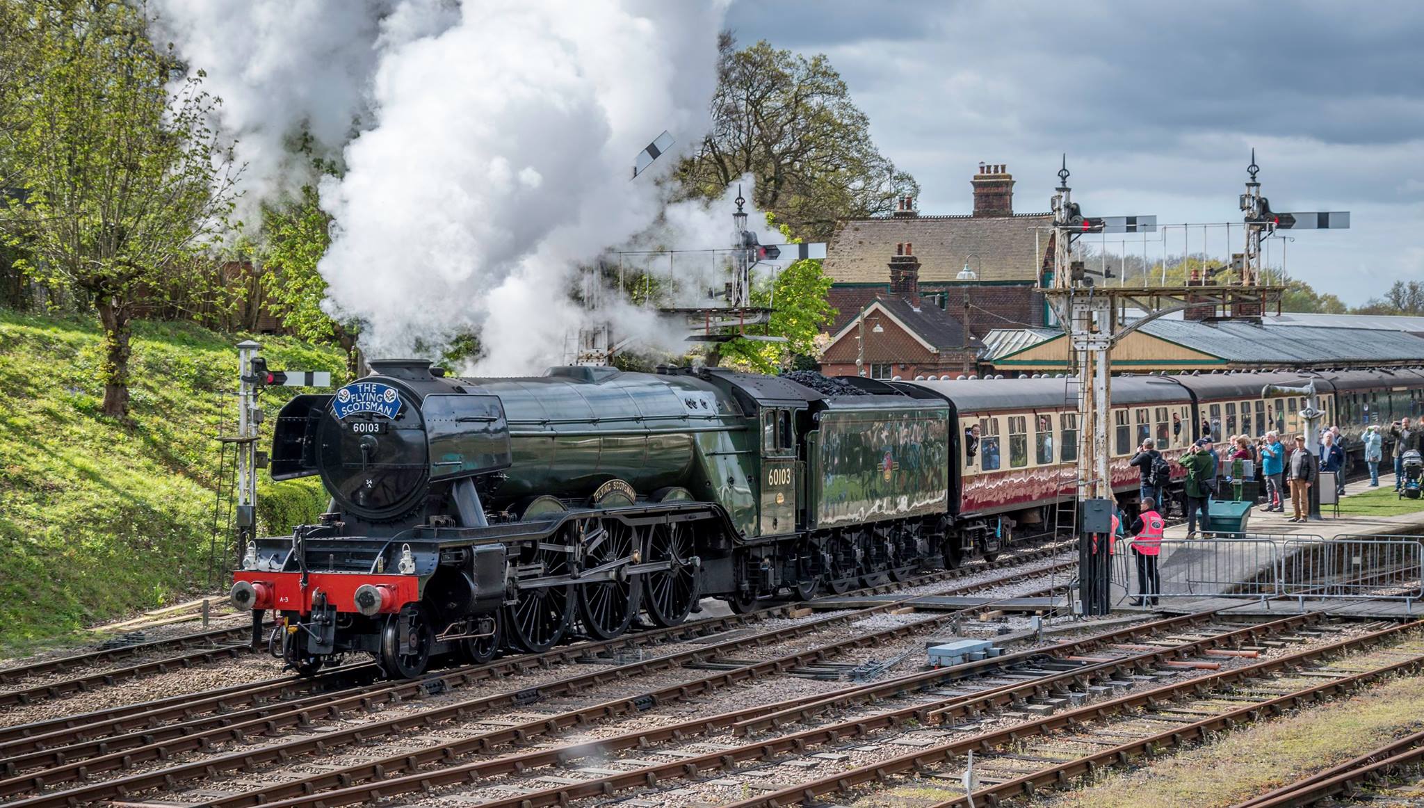
In 2004 an eager but very flu affected 7 year old got himself out of a sickbed to drive with us all the way to York to see and ride behind the Flying Scotsman. Imagine his dissapointment to find that she had failed and was in for maintenance. The Black 5 on the Scarbrough Spa Express really did not work as a substitute – by 7, he had already seen a fair number of Hikers by then!
So I promised that we would get to see her again soon and definitely have a ride behind her…… well it’s just neither I or the National Railway Museum thought “soon” meant 12+ years (and the small matter of £4.5m)!!! But Dad has done his duty as you can see…… even if the thrill to a 20 year old had waned a bit in comparison with the 7 year old’s which is definitely sad!
So enjoy a one of my pictures of her ladyship (or money-pit as some beleive!) and with thanks to Brian Dandridge for all of the rest of them as we were on the train and obviously could not photograph ourselves!! Thanks Brian!
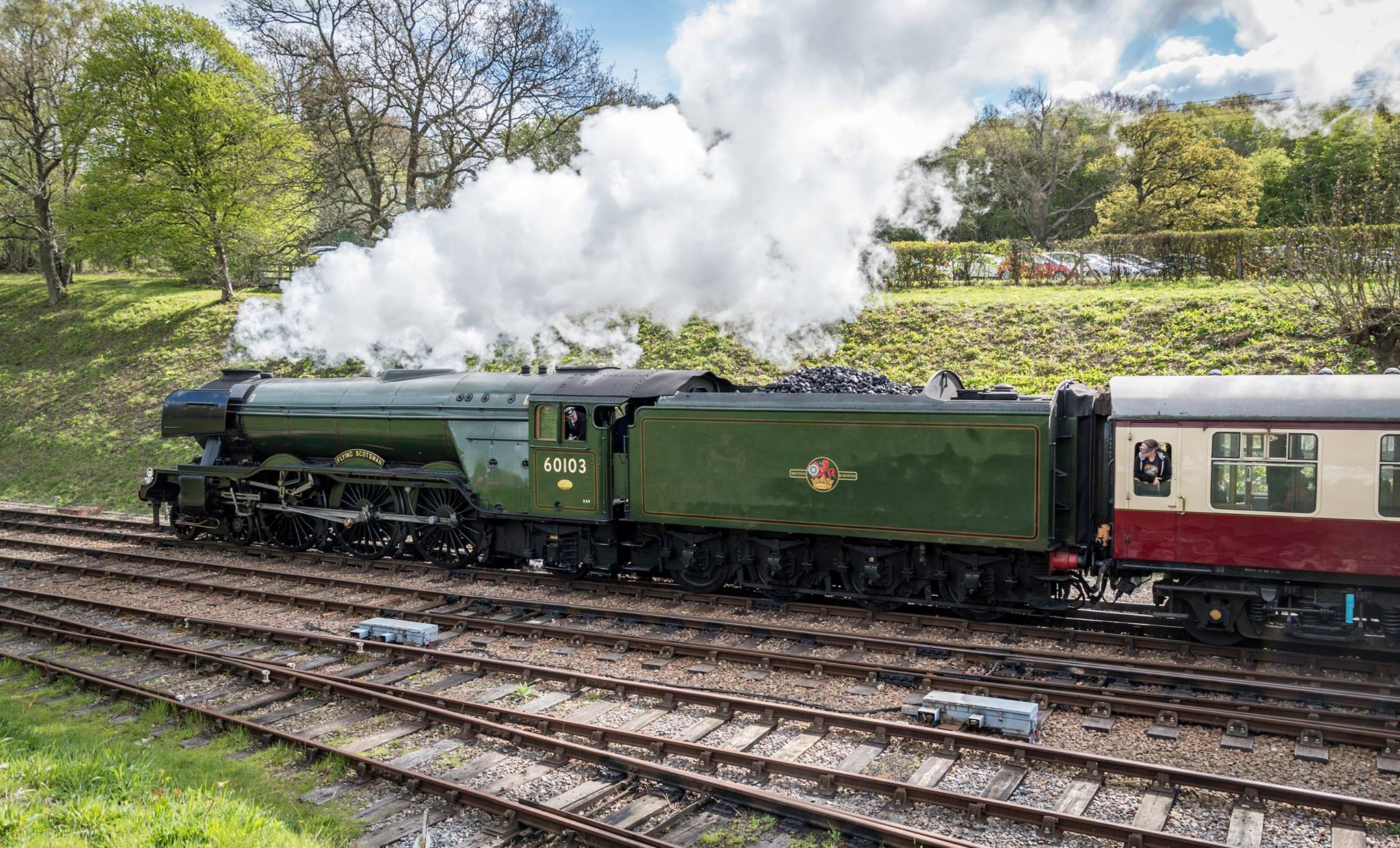
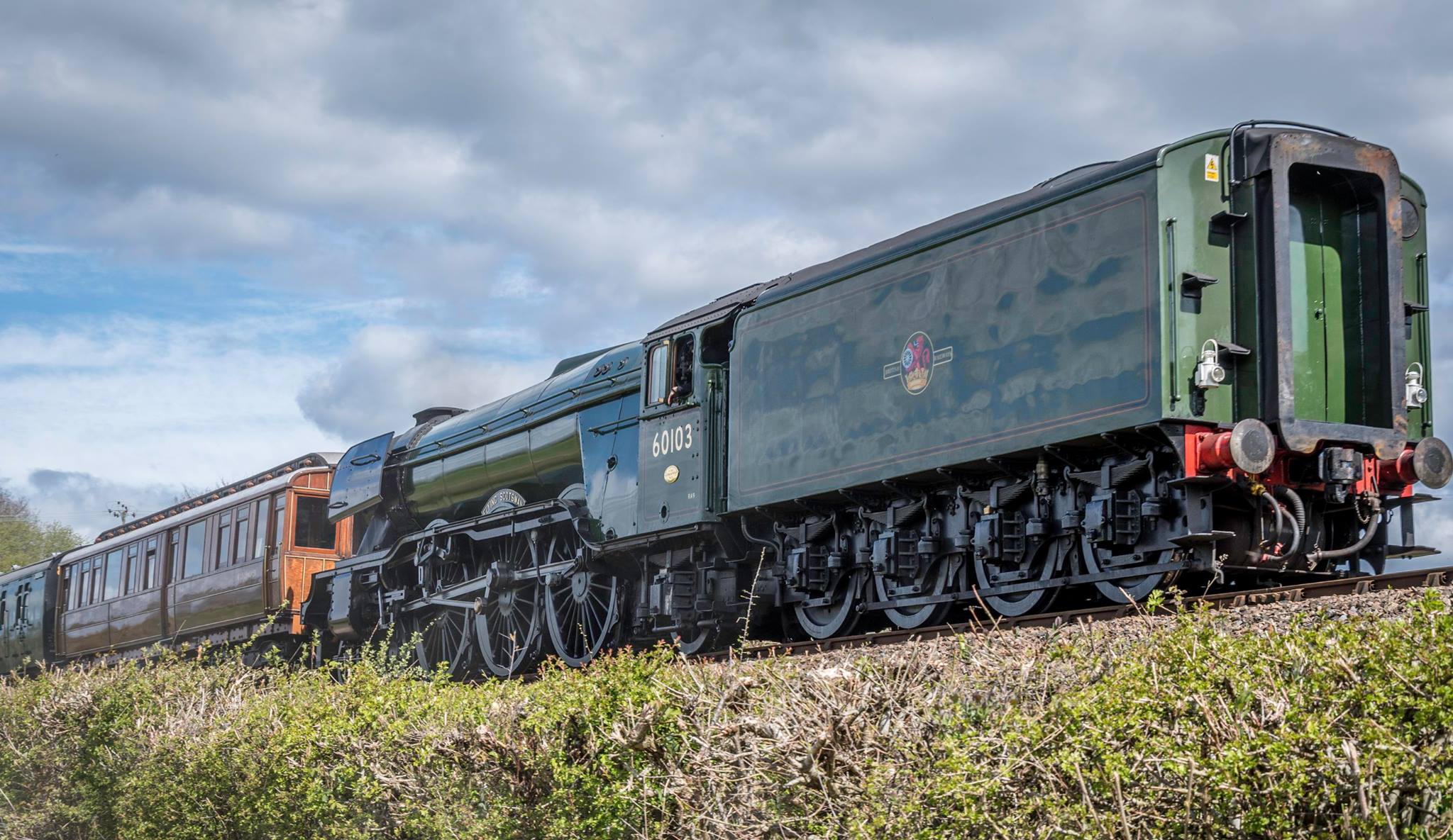
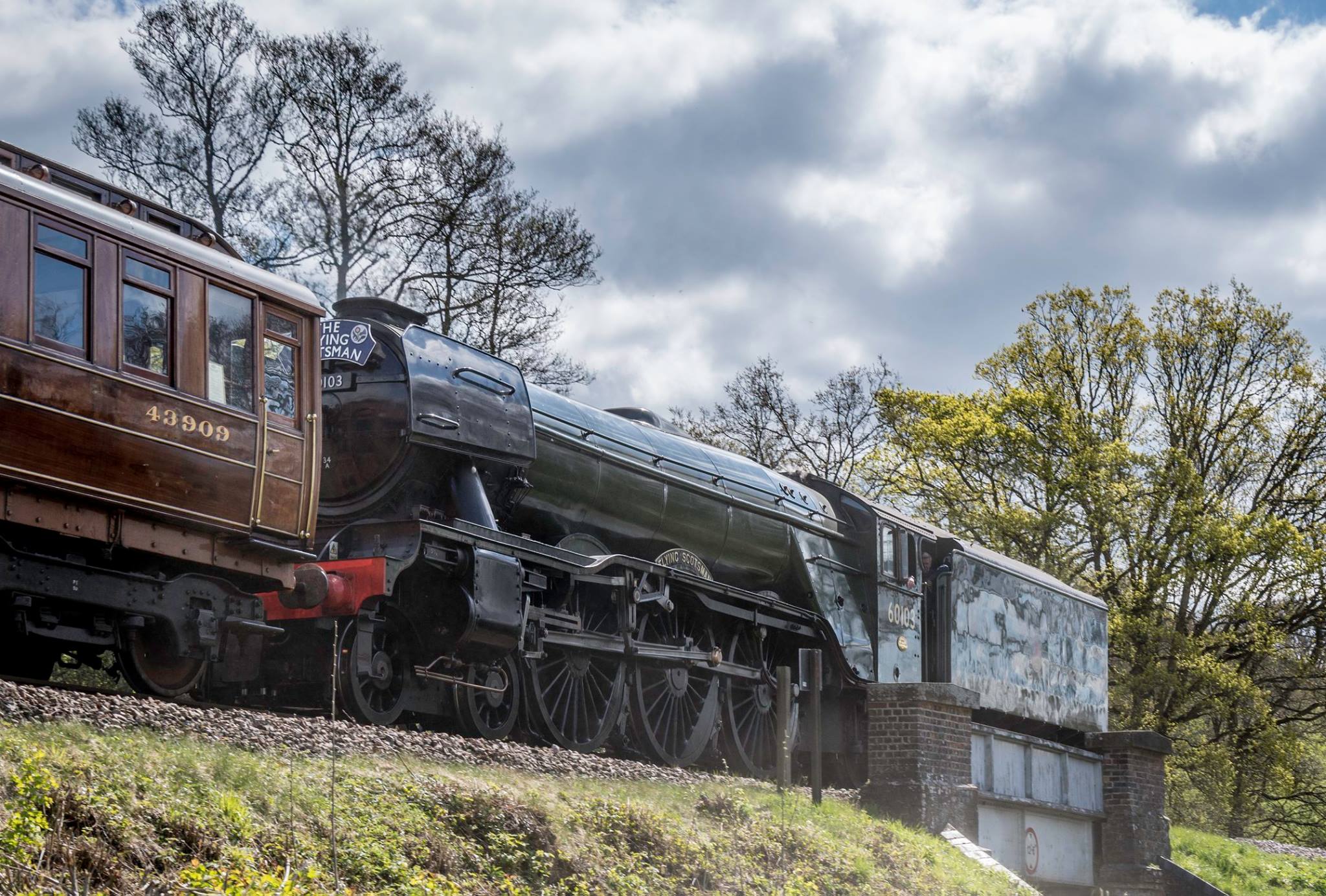
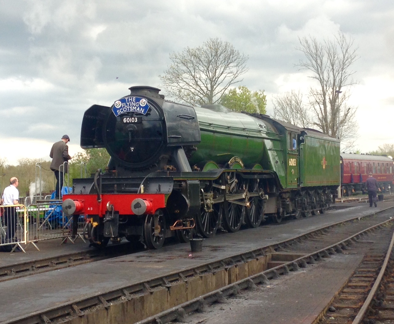
I have always felt the A3s to be one of the most attractive locomotive classes (although I do not like the german style smoke deflectors); if I were OTCM Oly I would be busy hatching a new layout plan……………..well maybe I am (……not, don’t worry but I do fancy an A3………..!)
Scrap Tank Test Build – Part 1; Getting Started
I took the weekend off the other week and attended the Spring Railway Modeller’s Weekend at Missenden. It is great to spend two full days just modelling away from the distractions of life and amongst people who are all doing exactly the same. I find it a form of therapy and it is well worth going if you have been thinking about it (and even if you haven’t!).
I took with me the etches that I have had delivered by PPD for the Scrap Tank; with a view to doing a test build using them. The origins of this class are some of the earliest locomotives built for the line; the Raigmore class. In an attempt to increase the life of these new enlarged boilers were fitted to them. Unfortunately for the Highland Railway the boilers were too heavy for their frames and consequently these cracked. This left the Highland with a number of new boilers, wheels and many fittings but no locomotives! Ever the frugal, they recycled these parts into a series of three shunting locomotives which were designed by Peter Drummond and these inevitably quickly picked up the name of Scrap Tanks.
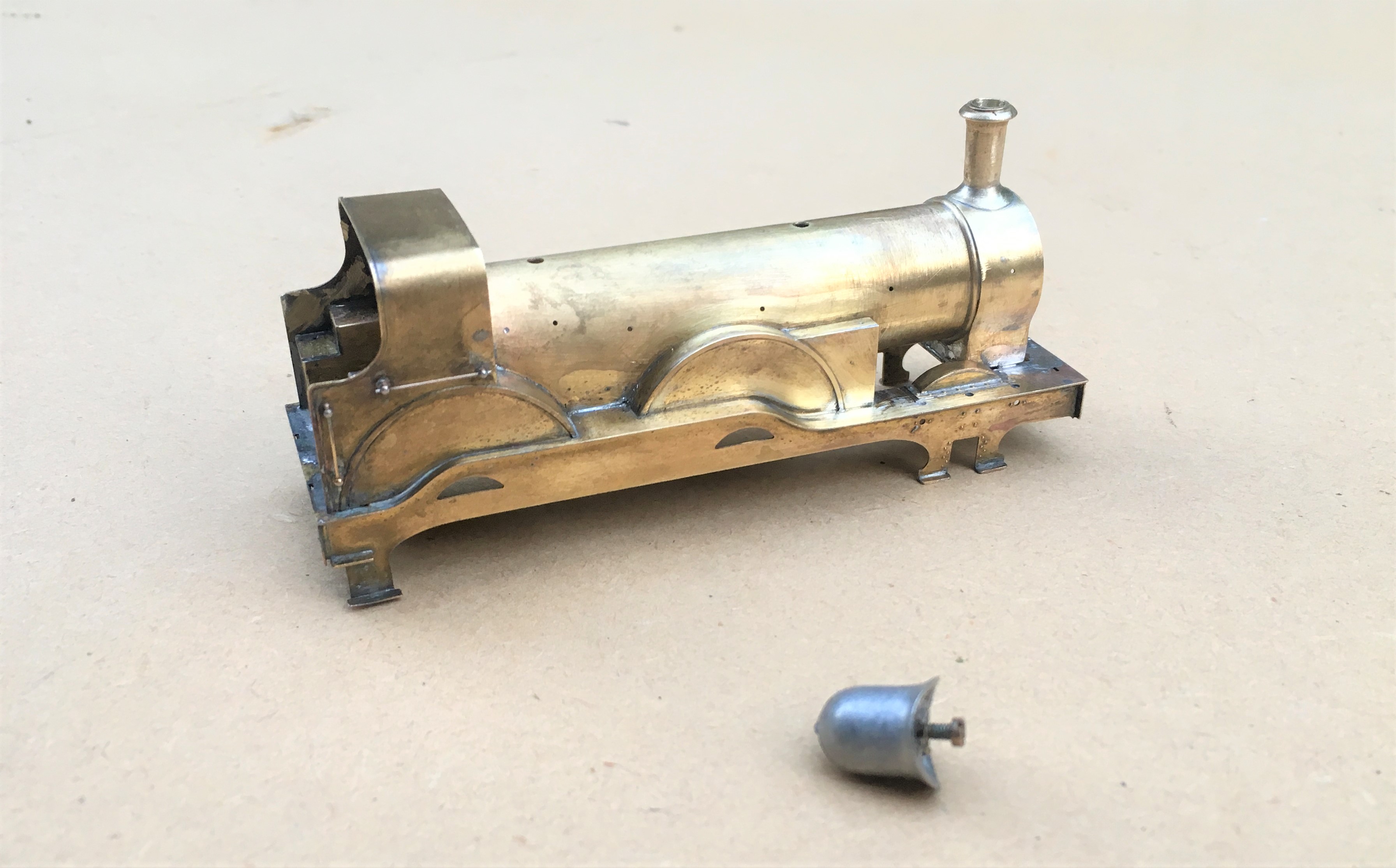
These were rather brutish looking locomotives for the time, characterised by surprisingly large wheels for a shunting locomotive – something compelled on the Highland due to them reusing these from the Raigmore class which were mainline passenger locomotives with 5′ 3″ wheels. For those of you who don’t know what these looked like, this is what we are aiming at:
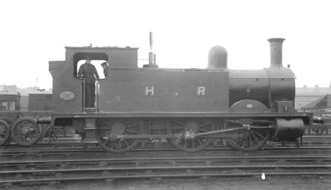
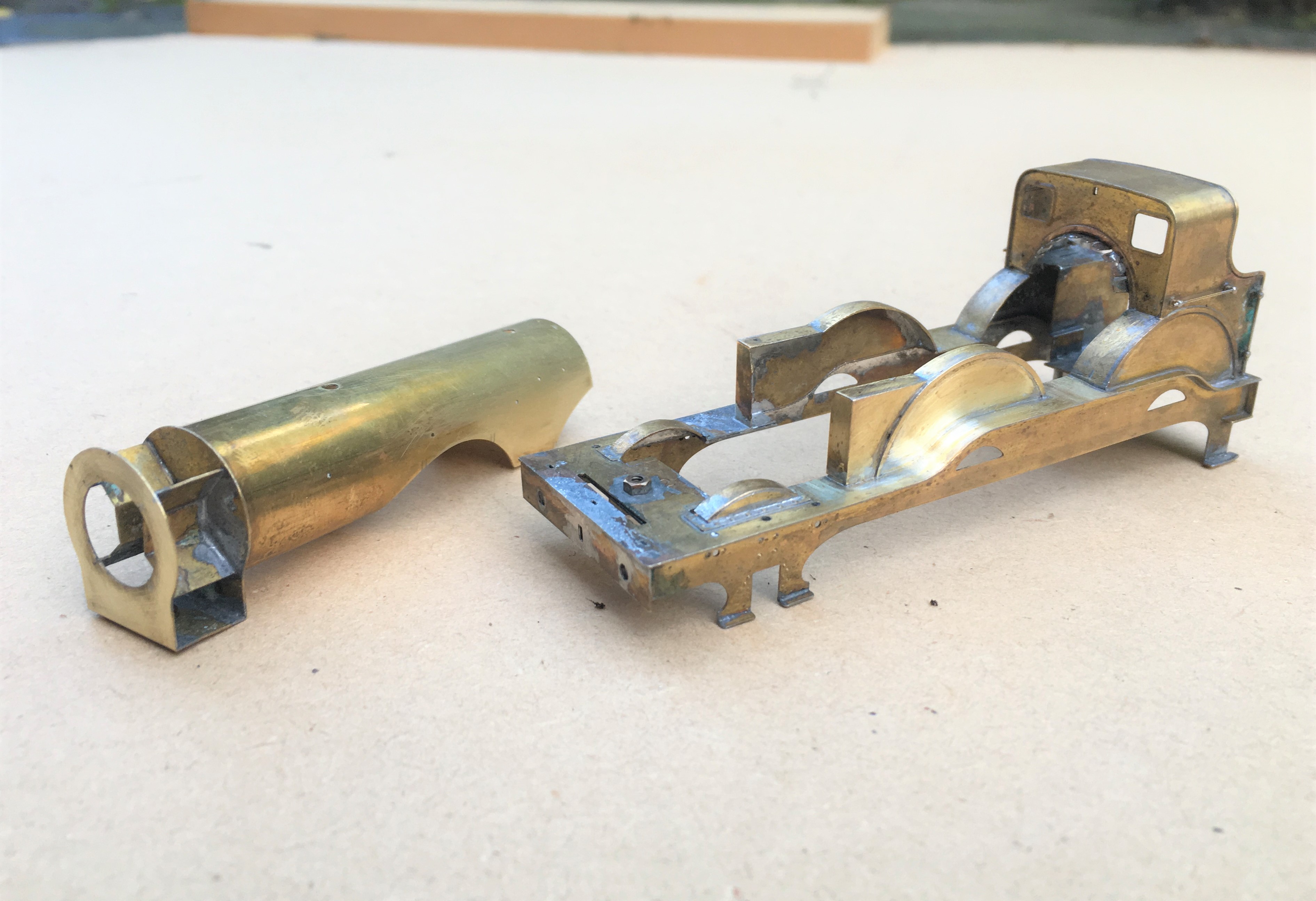
And this is what we are starting with:
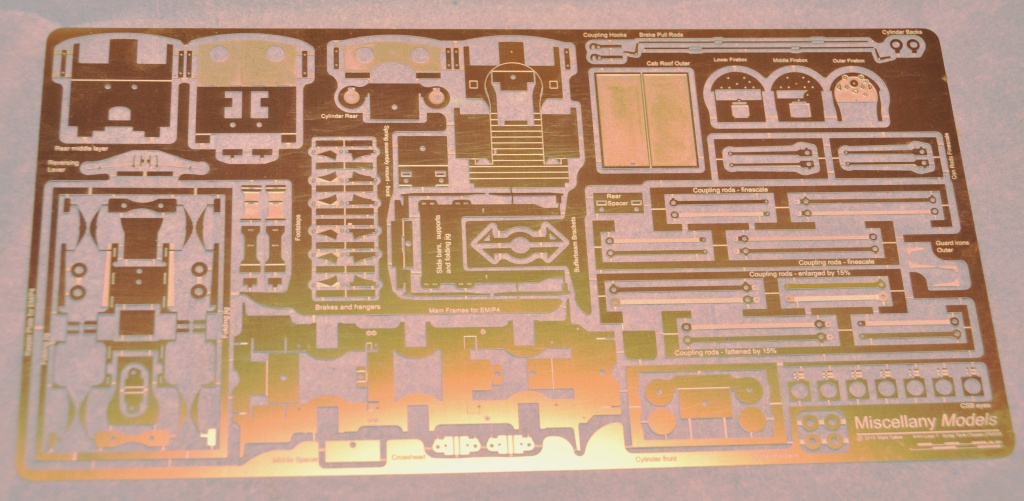
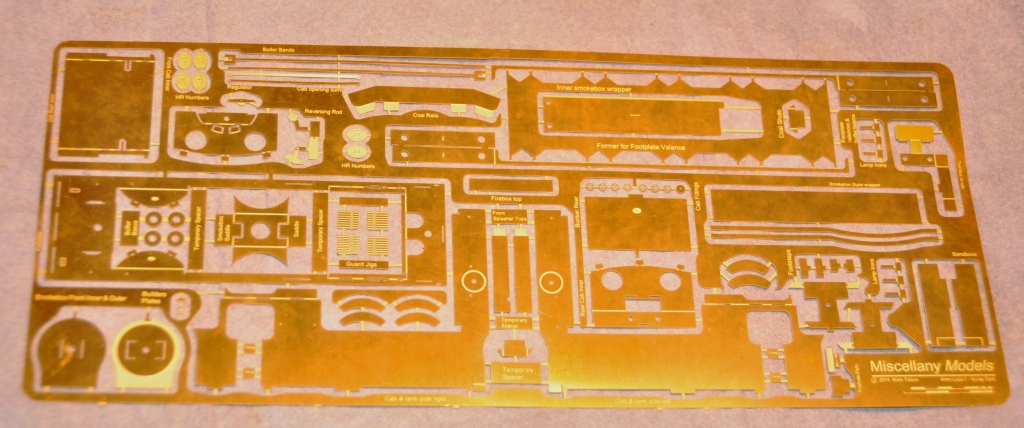
Whilst this may (well has!) got me into some trouble, I have sought to design the kit to be easier to build than the average etched brass kit and certainly easier than the Falcon Brass kits that are the staple in 4mm for many of the Highland’s locomotives. I have sought to do this in a number of ways and the first area tackled, the cab front/interior, illustrates one of these; the use of fold up assemblies to assist not only in creating the shapes but also the laminations. Many of the modern etch designers are using these (especially the 2mm boys/girls) but I have sought to do rather more than most (which has made the preciseness of the design rather more challenging, more of which anon).
The bulk of this assembly starts as a single piece, that is folded up to form the cab floor, splasher sides and the bulk of the cab front. To assist the lamination process, jigs either side of the cab front have been used. Wire rods are slipped through the small holes in these to ensure that they are registered on top of each other properly.
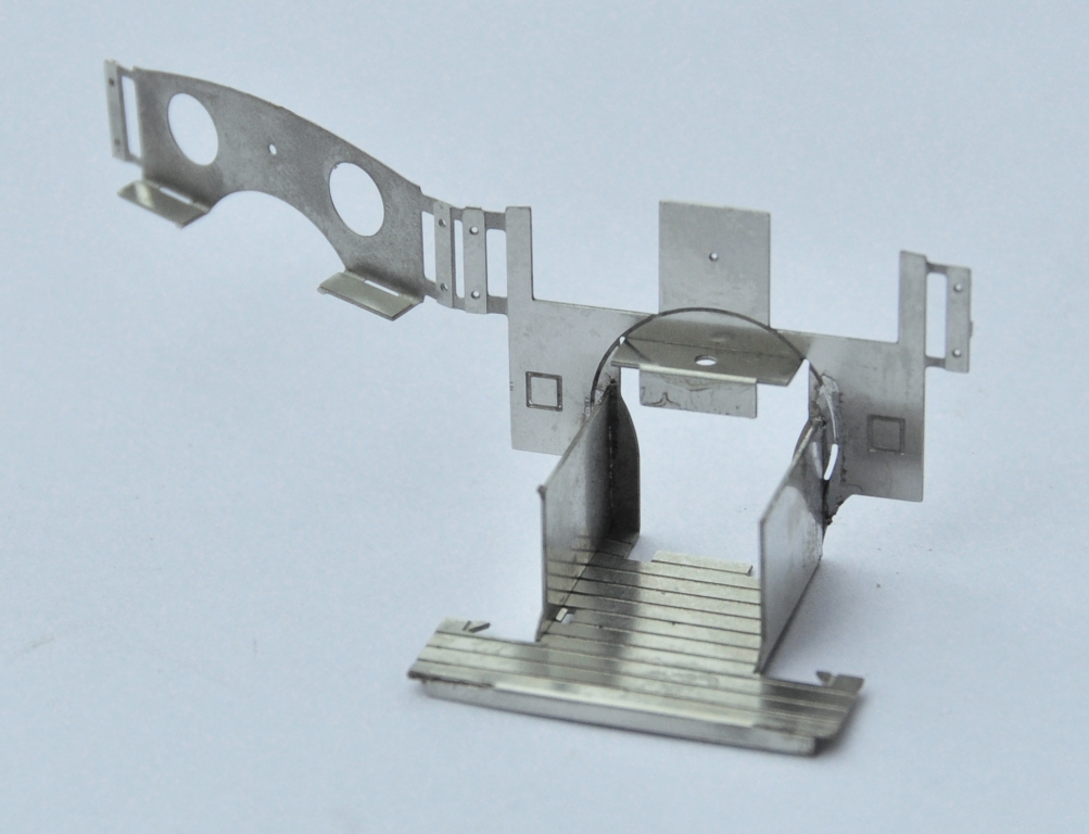
The view below shows the laminations now sweated together and illustrates the square cut outs behind the cab front which are to enable glass/Perspex to be slotted in to represent the sceptical glazing. The view also shows the boiler backhead which is made from three layers of etch (not with a folding jig – yet!). I am pretty pleased with this as this is only 13 * 15mm in size, so the wheels on the backhead are only 2mm in diameter.
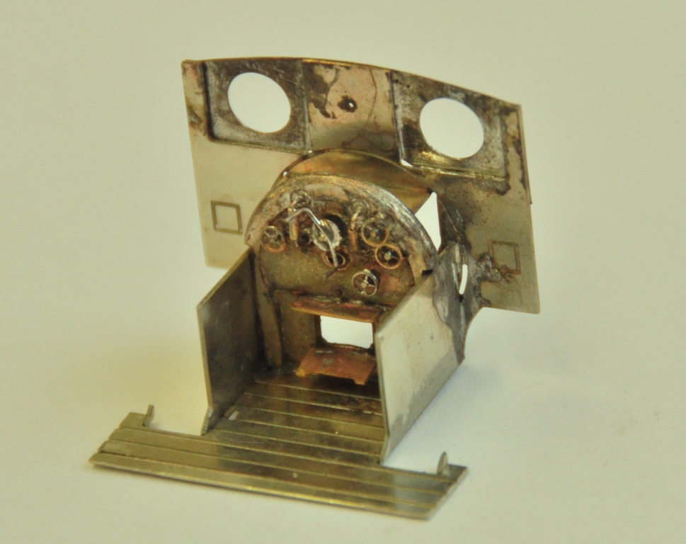
To be continued…………(soon too!).
