Blog Archives

Fuel for Thought
Obviously, where there is water in a locomotive yard, there really ought to be coal too.
The Highland, like many other railway companies of the time (certainly the Scottish ones), sought to stockpile coal. This was presumably insurance against coal strikes and allowed them to purchase coal at times when the price was favourable. Thus, quite substantial coal stacks where very much a feature of shed areas in the pre-grouping era. Typically, these were arranged in engineered stacks, with the sides formed in “dry-coal walling” and then loose coal behind. I can’t recall ever seeing this modelled, so I though I would change that!
The actual structure of the loading bank was formed in plasticard and Wills random stone sheets, but with the mortar courses softened as I described for the water towers. The shape of the coal stack was formed with a piece of house insulation left over from a DIY job and then real coal used to form the effect of…..err……real coal. Actually, real coal does not look quite like real coal without a bit of effort. It does shatter into angular but irregular lumps like real coal (especially if lignite coal is used) but its glossiness does not scale down. However, a vigorous brush with generous amounts of soot black weathering powder takes the gloss back and the whole becomes quite convincing. You do feel as if you are going to get pretty filthy if you go up onto the bank – and until the whole is fixed with matt varnish, you would!
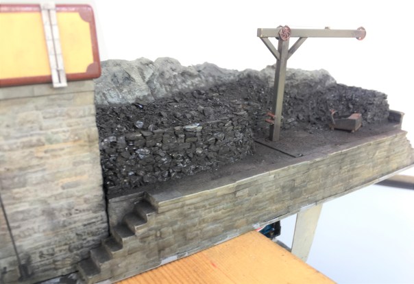
Individual coal chunks were glued in place to form the wall structure. To get the effect, it is not enough to simply scatter the coal onto a bed of glue each chunk has to be laid individually with care taken to lock it into the course below – just like a real dry stone wall. Thus, the vertical walls of this took about a day to complete, scattered over about 8 stints because it is necessary to let the glue dry after every couple of courses to stop the layers collapsing. It is then possible to scatter the loose material behind the walls onto a layer of glue – the above picture shows the contrast in effects between the two methods.
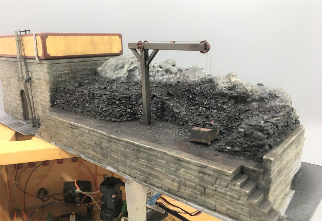
But it is hard work shovelling coal into tenders, especially as the locos got larger and their tenders higher. As befitting such an important place as Glenmutchkin, it has all the modern amenities for coaling engines, a hand crane and a large bucket! In this case, I have fitted servos to this so that it operates – partly as a bit of fun and also to slow things down in the yard to a more realistic pace without it getting too boring for the viewer.
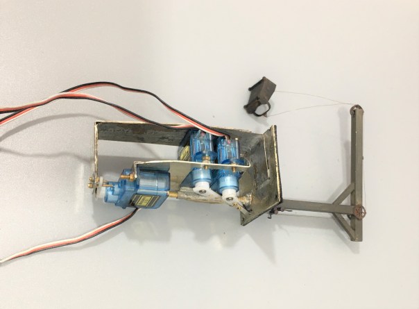
The crane operation was achieved by way of three servos – one to rotate it and then one each for the front and rear of the coal bucket. These are all mounted onto a cradle that is rotated by the former – thus as the crane rotates so too do all the servos and there is a quadrant shaped slot in the base to the rear of the post (just visible in the picture above) that allows the cables to rotate too without snagging.
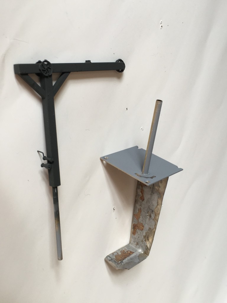
The cradle is mounted to a solid rod that is in turn secured to the actual crane. This then slides into the rod that can be seen projecting from the base in the picture above. This means that there is limited strain on the crane or the mount as I had feared it might otherwise snap with any heavy-handedness on my part (something I am prone to!). The rest of the crane was made with brass hollow section and pulley wheels from Bill Bedford. A series of guides were made of small section tube on the pulley wheels, at the winding drum and across the jib to retain the operating cables.
The bucket was fashioned from metal sheet and is filled with low melt solder to give it as much weight as possible. It is secured to the servo arms with invisible thread – which is a nylon seamstresses material used for making invisible stitches. It comes in both clear (which really is invisible) and black, I used the latter. It is much better than cotton thread as that has a furry finish that looks terrible after a time or if it is painted. It is, however, very fine and rather wriggly to knot, so using it involves a certain amount of cussing!
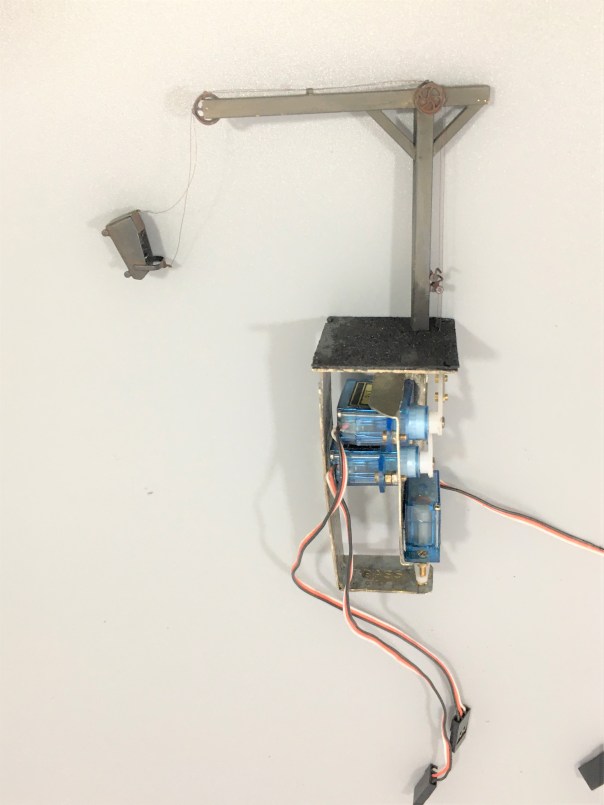
And this is what it looks like in operation…………
A little of the bouncing about of the bucket is caused by it sitting on my servo test rig, so the act of changing the switches imparts a little vibration. Hopefully, when mounted on the layout this will be less obvious.
I do still need to do the final detailing on this; tools, a bit of discarded debris and a couple of fellas from Modelu standing around doing nothing (because static people in animated poses look silly on a model layout!).

Let There be Water…….3 – Now There is!
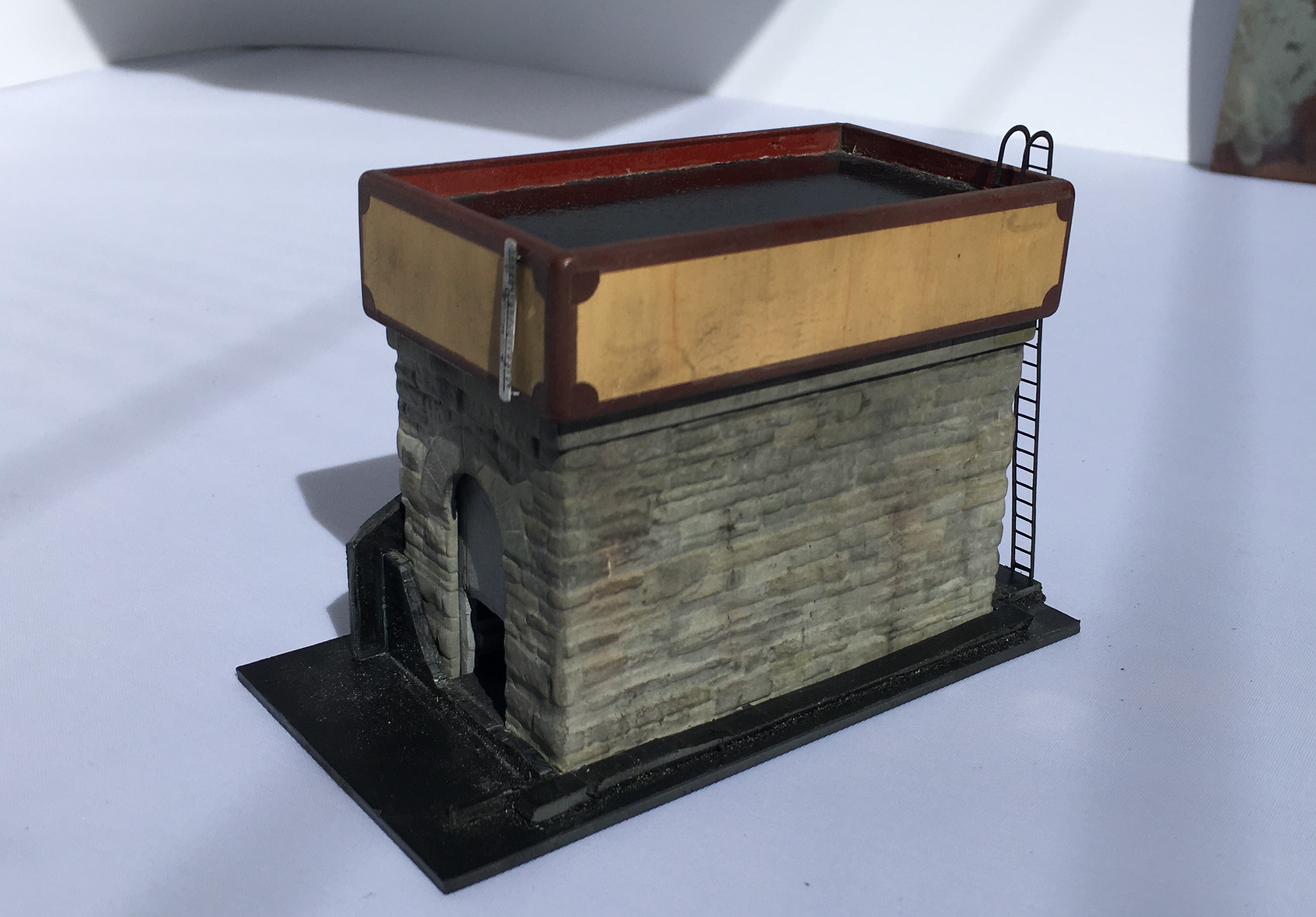
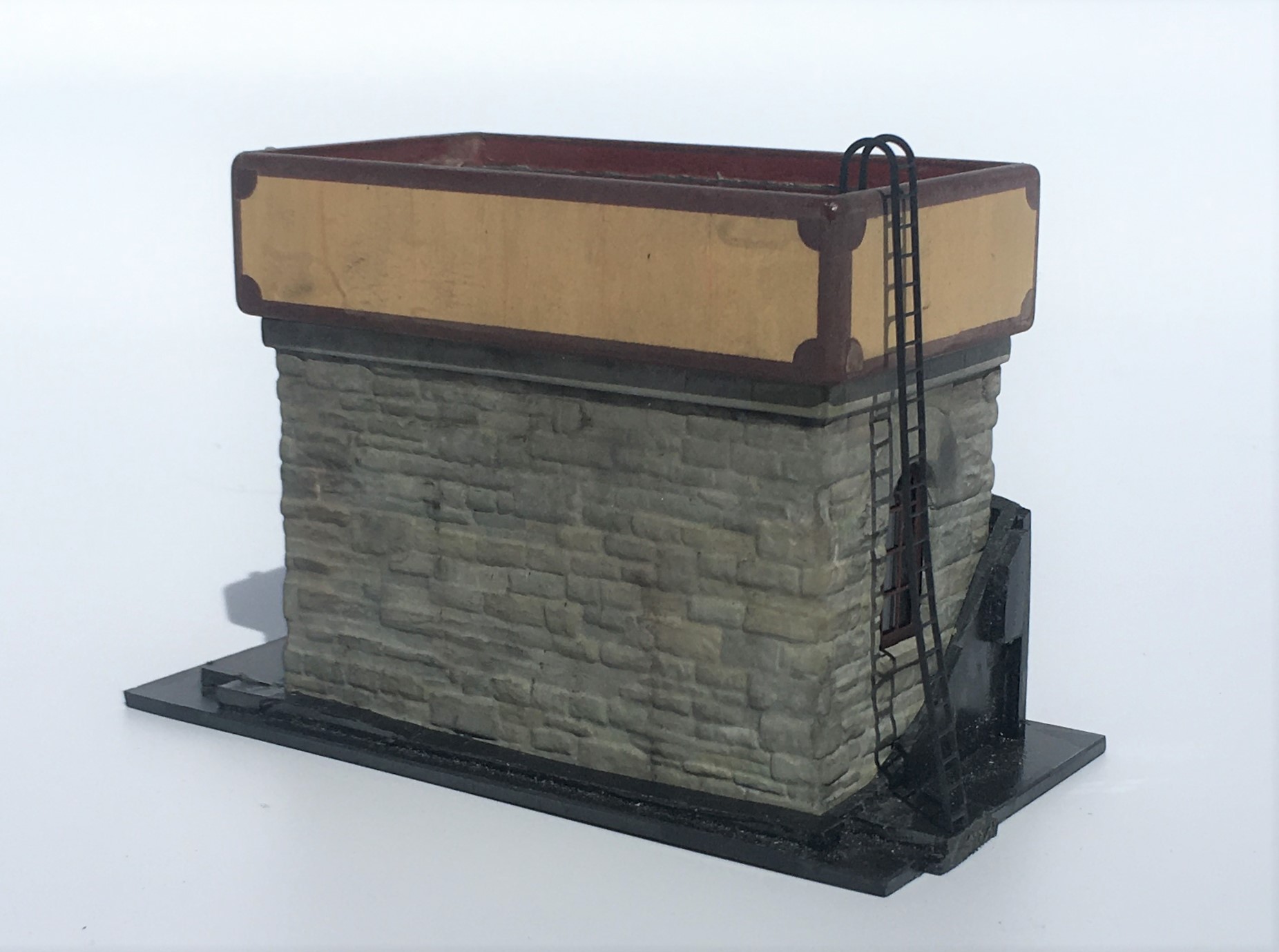
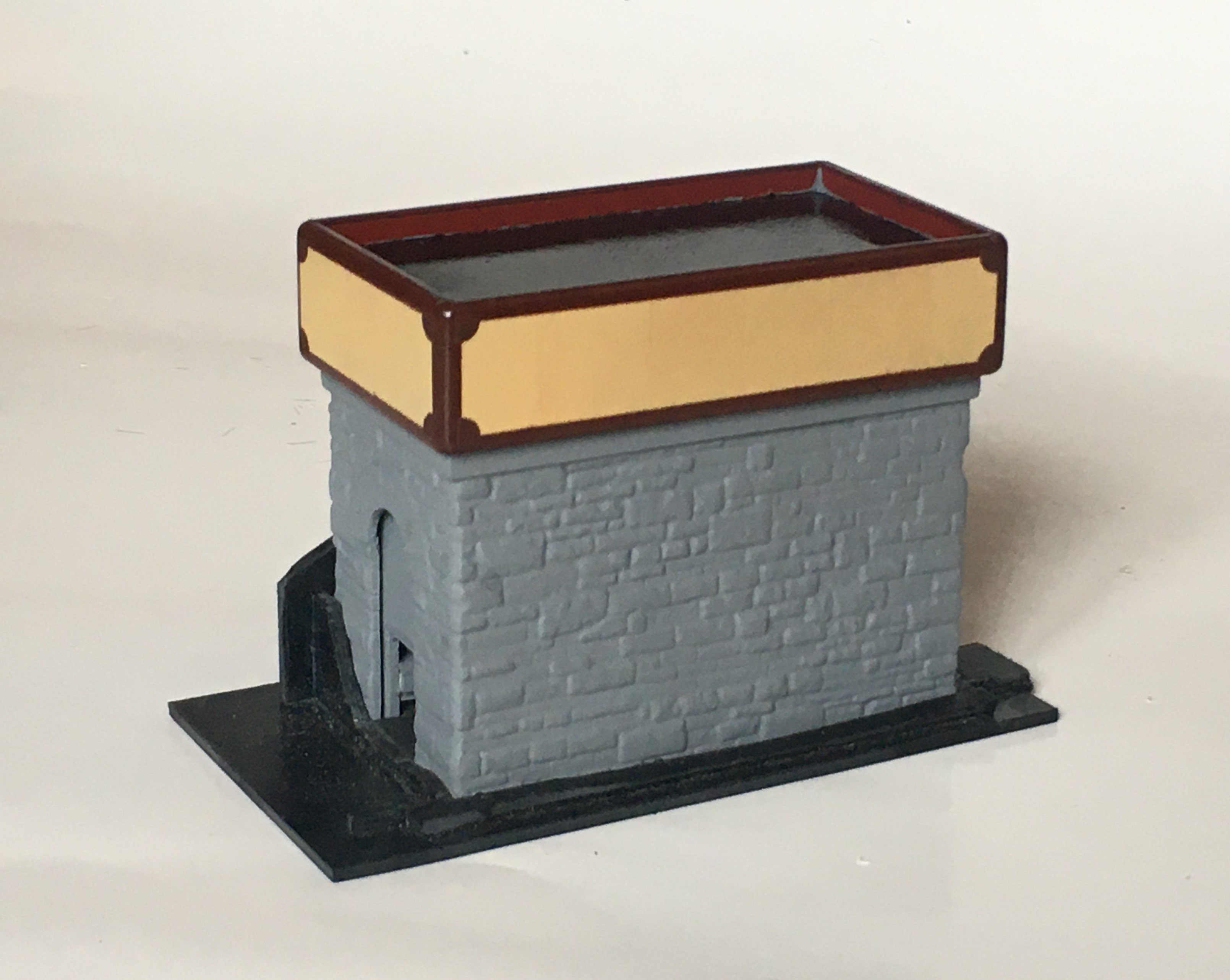
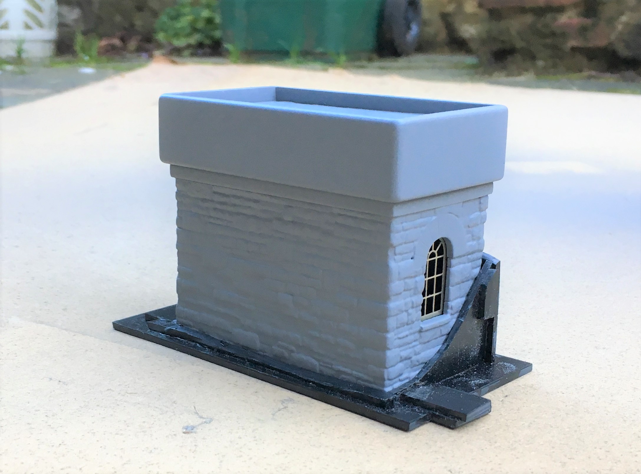
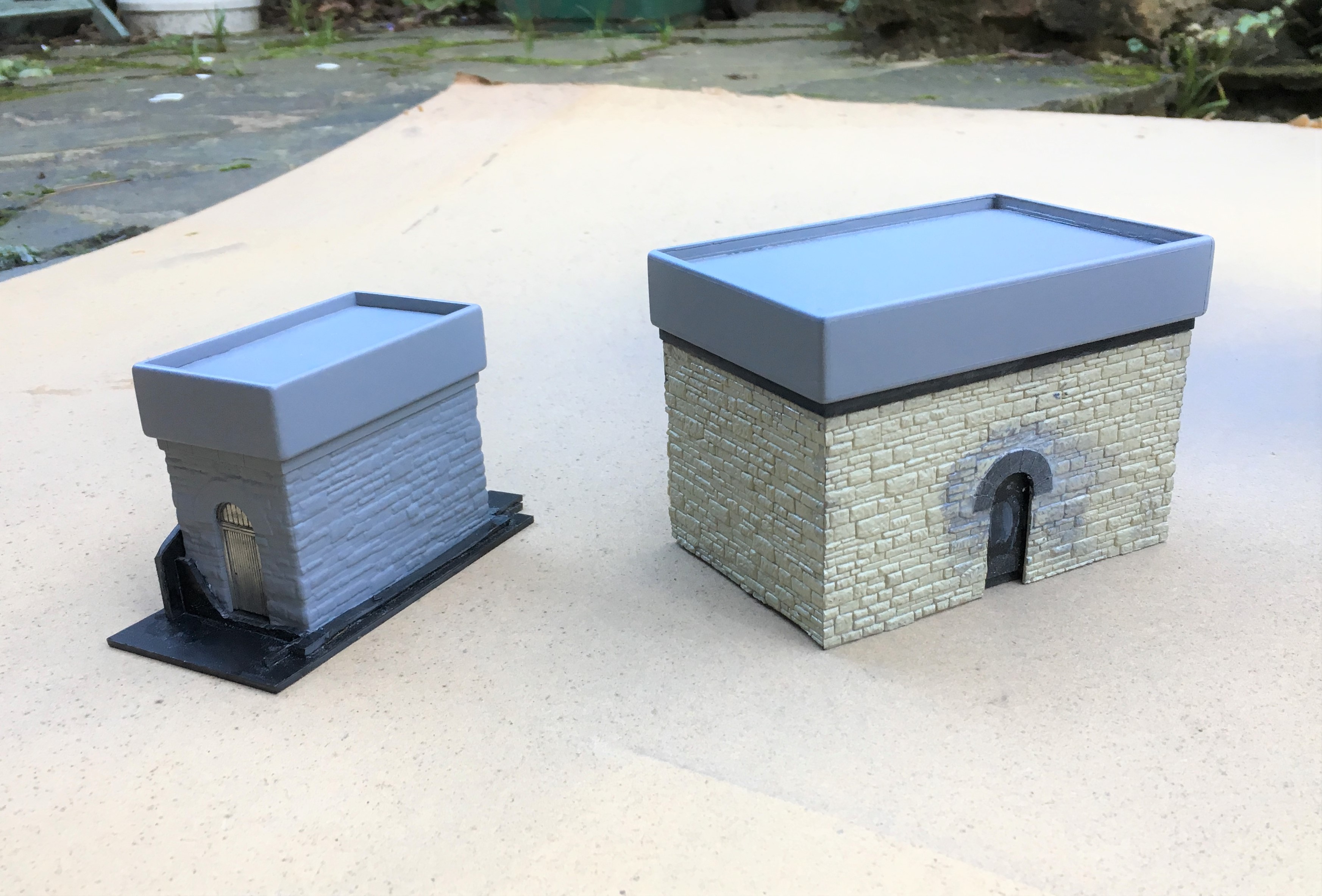
More progress has been made with the pair of water tanks and they have now reached the stage where they are effectively finished.
The stonework was painted by picking out each stone in different colours. I think there is a real art to this as when I see others do this, I often think the colour differences are unrealistically abrupt. I find the trick is to use a core of two colours that are close to the general colour that you want – in my case Humbrol Matt no 5 & 64. Put these in separate palates on a mixing dish and dip into these to create a combination of the two.
By selecting two relatively close colours, you can alternate from all one to all the other and any mix in between. Adding very moderate amounts of a stronger colour difference, in my case Humbrol Matt 66 and 62 which are a darker grey and a leather brown adds a bit of variety but in each case they still need to be mixed in with the two core paints to keep the toning consistent.
Even with this work the colours didn’t seem quite real, so I completed two additional steps. The first was to use some matt varnish that I knew the matting agent was a bit gone on – this gives a slightly translucent milky effect over the whole and drew the colours together a bit. The second was to use AK Abteilung 502 weathering powders – black smoke, ashes grey, gunmetal and rubble dust (primarily because these were the only colours I had!). These need to be used with care, as it is easy to put way too much on and you can’t generally get it off again! However, at low level and to the coal bank I have been pretty liberal with particularly the black smoke as such areas were far from clean!
The weathering to the water tanks was dealt with slightly differently, although it also started with the use of the acrylic varnish with the defective matting agent (that’ll be how I found out it was defective!). I then used a Humbrol dark grey was with downward brush strokes and then wiped off with a piece of kitchen roll, again with a downward stroke. A few additional marks, especially to the panel joints, with AK Interactive weathering pencils.
The water effect was another accident flowing from the defective matting agent – the milking was far from desirable on the black base coat of paint. Thus, I wiped it off once it was semi dry and I got most of it but where the remainder was still there, it added a bit of texture to the surface, as if there was a little disturbance to the water that affects part of the surface not the whole.
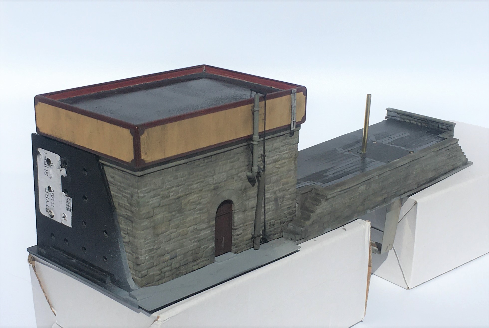
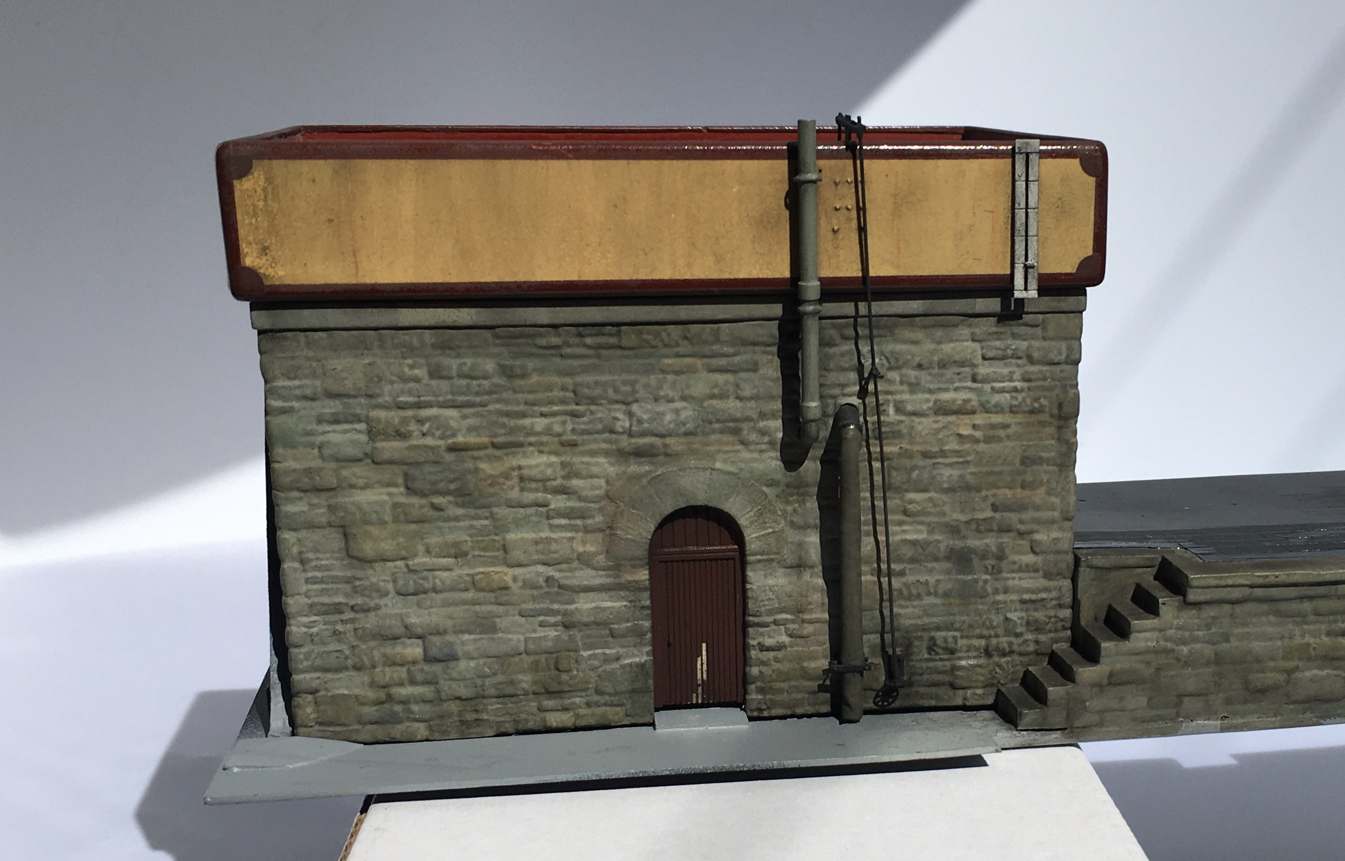
By reference to the prototype, I made a heating stove flue and spigot for the water bag from brass rod. To form the bends it was necessary to have a pair of additional tubes inside each other to stop the tube collapsing on the bend, The canvas section of the leather bag was formed by a piece of heat shrink sleeving but with a little 5 minute araldite in the centre such that as this starts to cure a degree of shape can be put into it and once fully cured it will stay in this shape.
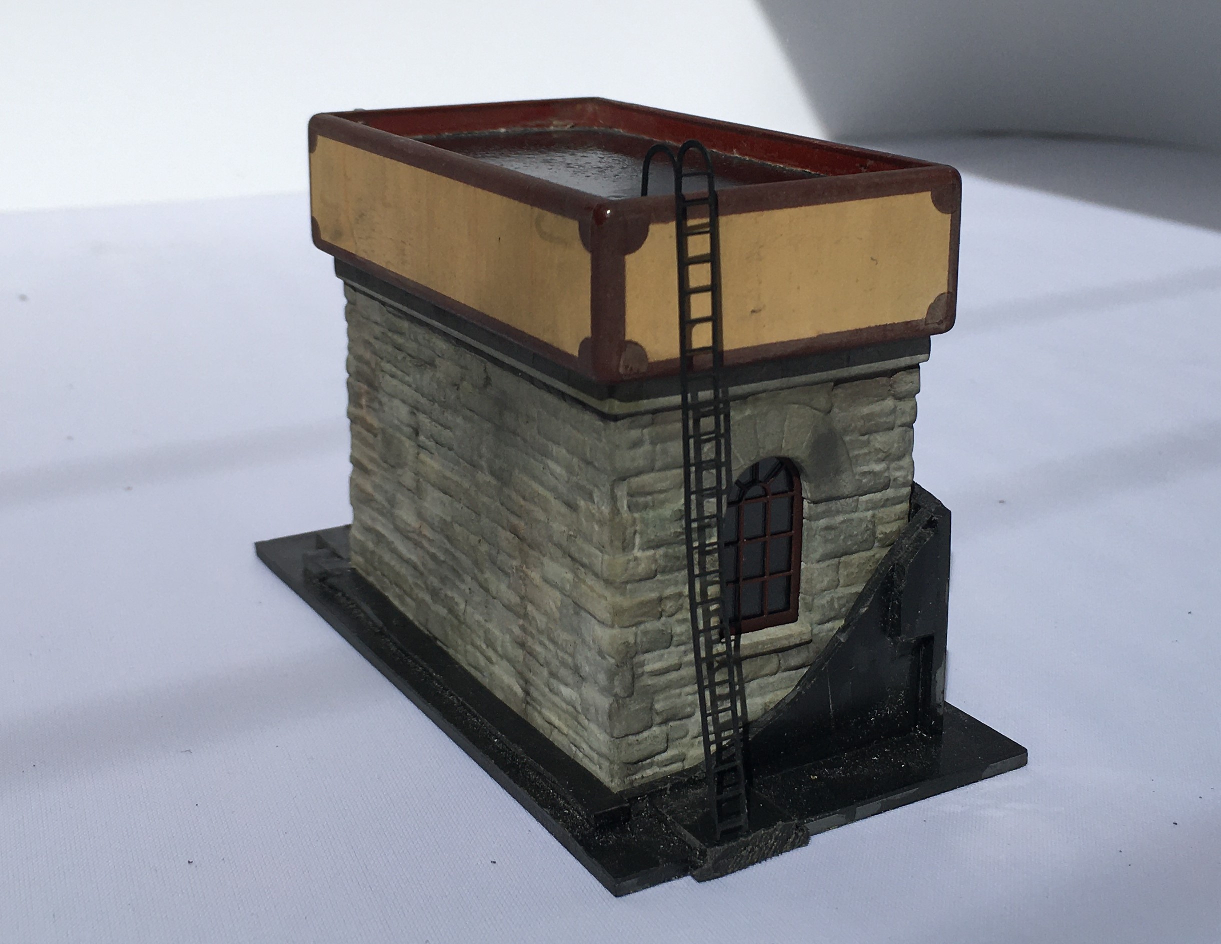
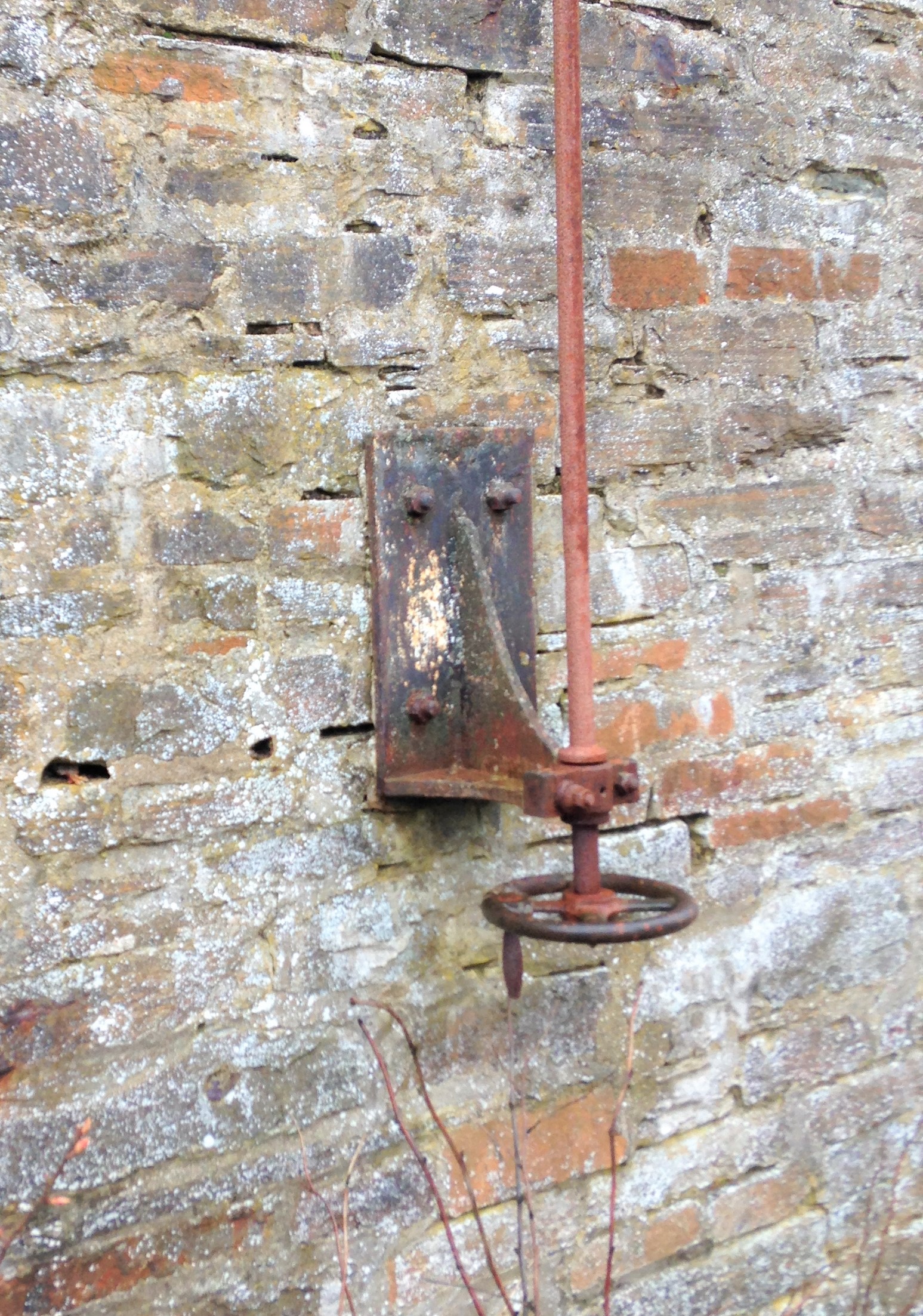
The operating rod was based on that still largely apparent at Altnabreac and I have assumed this also had a ladder even if this has now gone. There is no watering bag to the smaller of the two water tanks as I propose to have some water columns, but that is a story for another day!
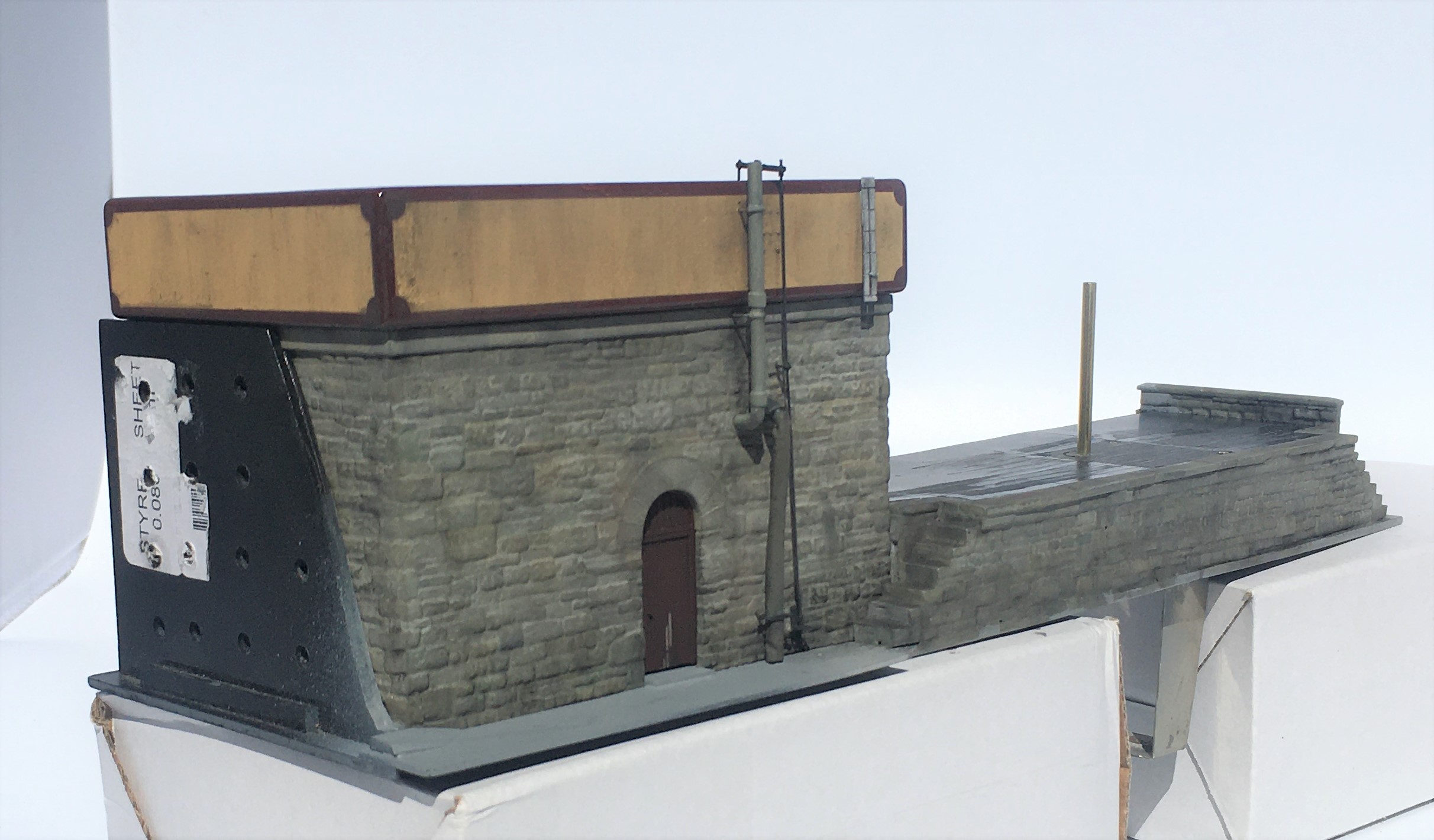
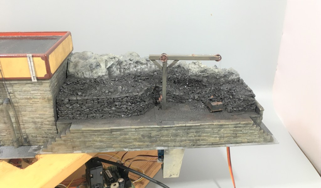
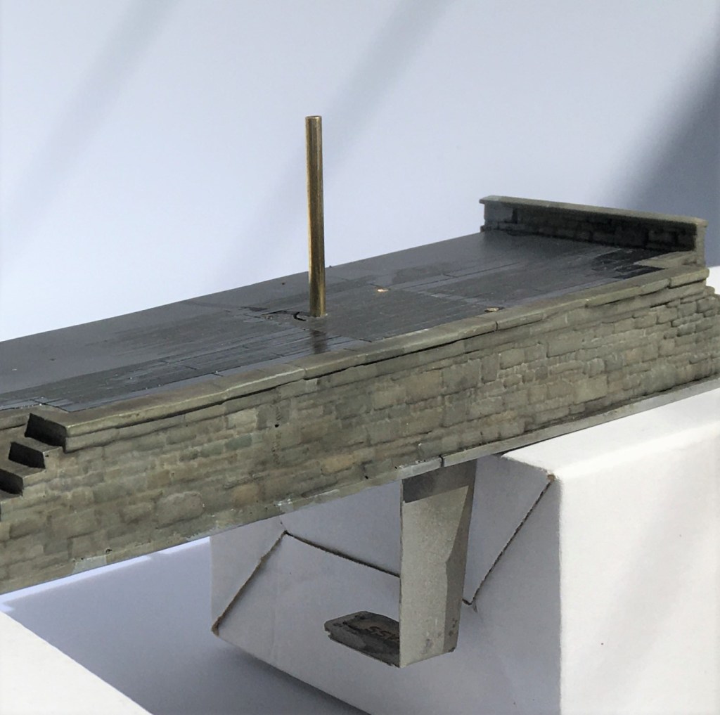
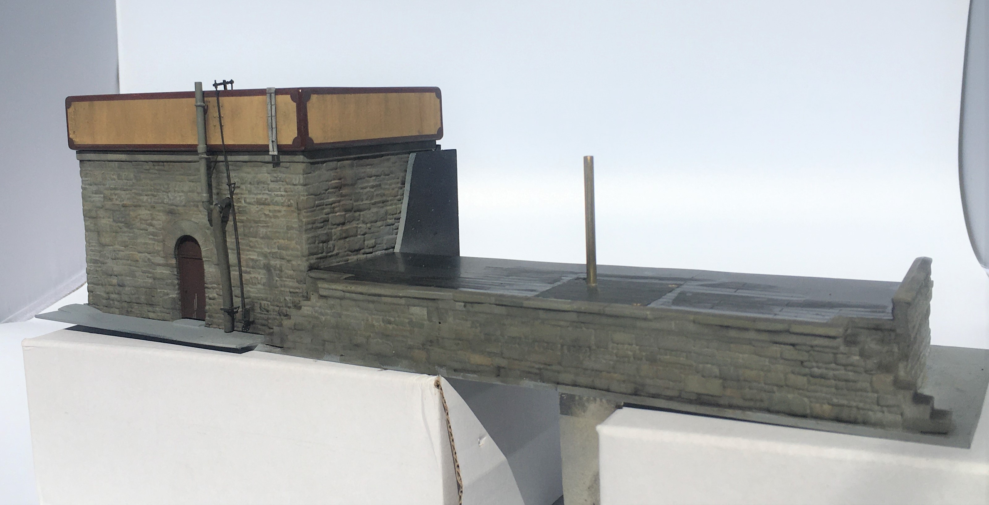
A further story for another day is the rather odd post sitting in the middle of the coaling bank; but that story will be fairly soon!
……part 2")
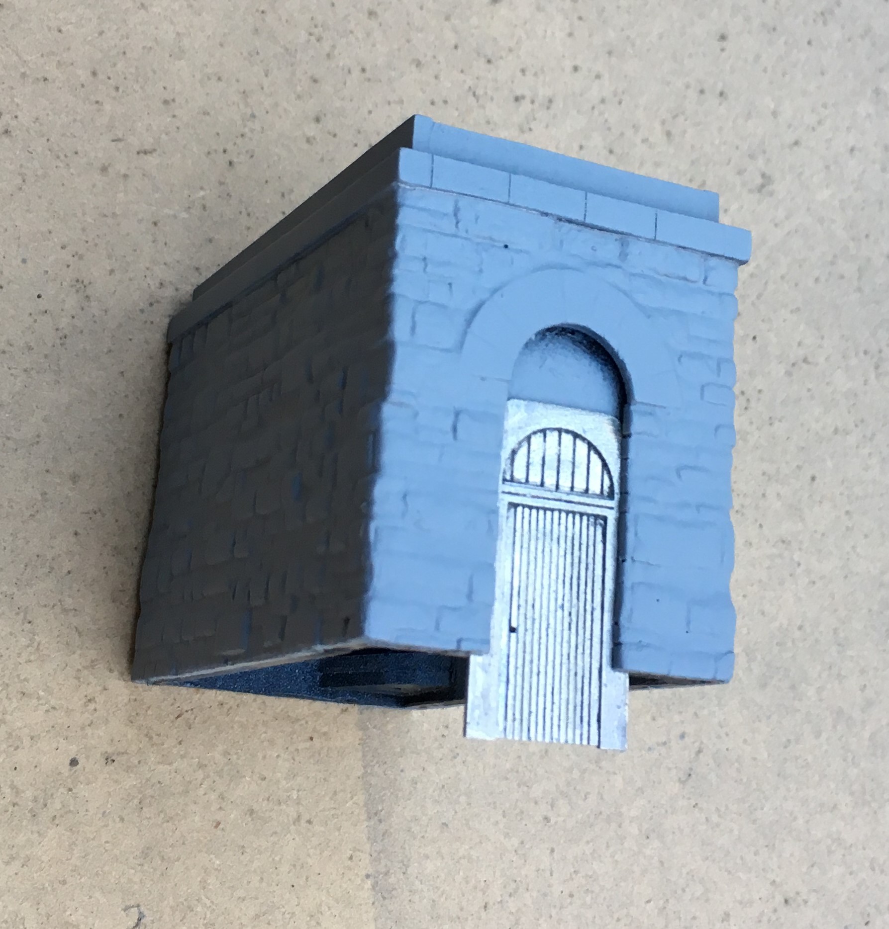
Let there be water (and coal too)……part 2
One of my pet hates on model railways are buildings that float a fraction above the ground because they have been plonked in situ, not bedded in. For me, it completely destroys the illusion and I can get quite wound up about it when I see it (…..and it is pretty common, so this is fairly often!).
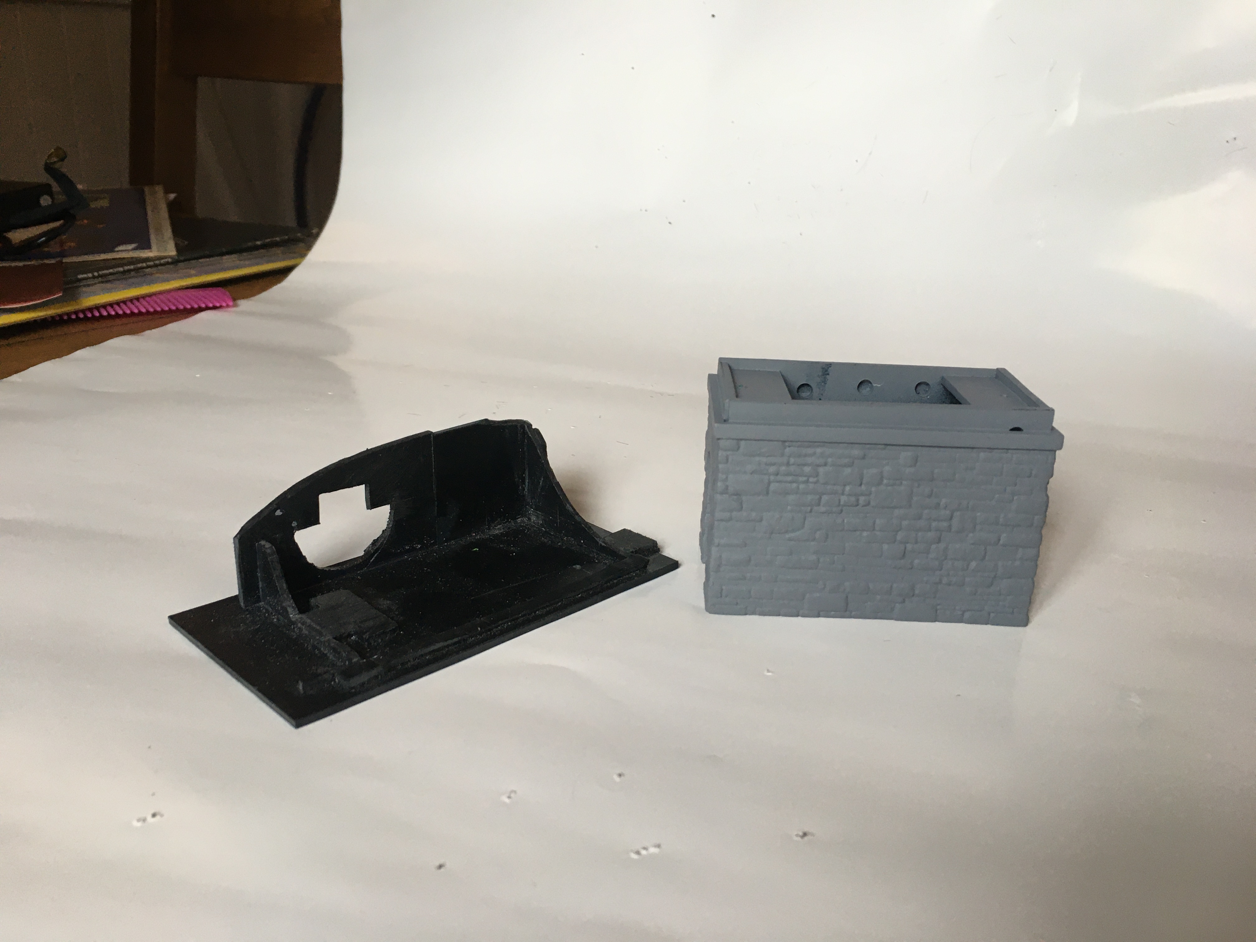
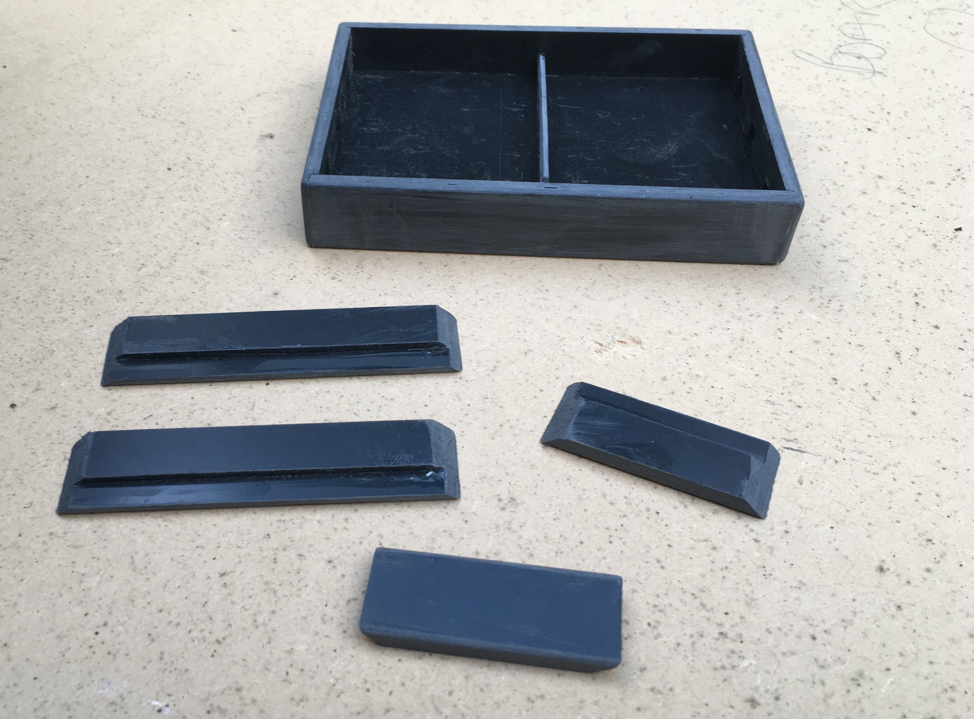
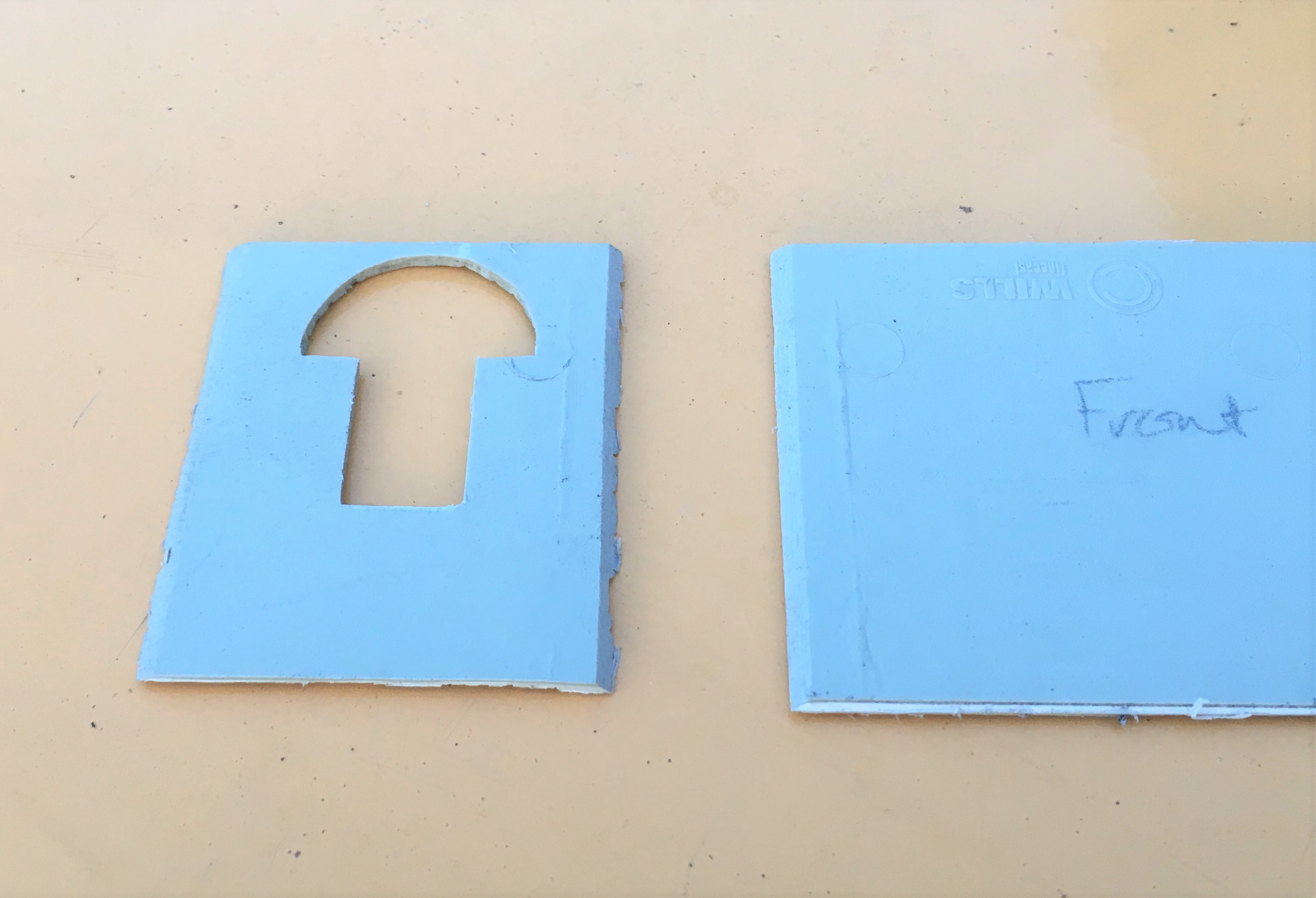
Occasionally, I actually do attach the building to the baseboard and “scenic in” the ground around them but more normally I construct a base into which the building sits. This gets embedded permanently and then the building sits into a slot that is formed into it. I have also seen the building being built in two parts, with the base being affixed to the ground and the building slotted onto them. Peter Bond did this for me with the signal cabins for Portchullin. This is the base for the larger water tank:
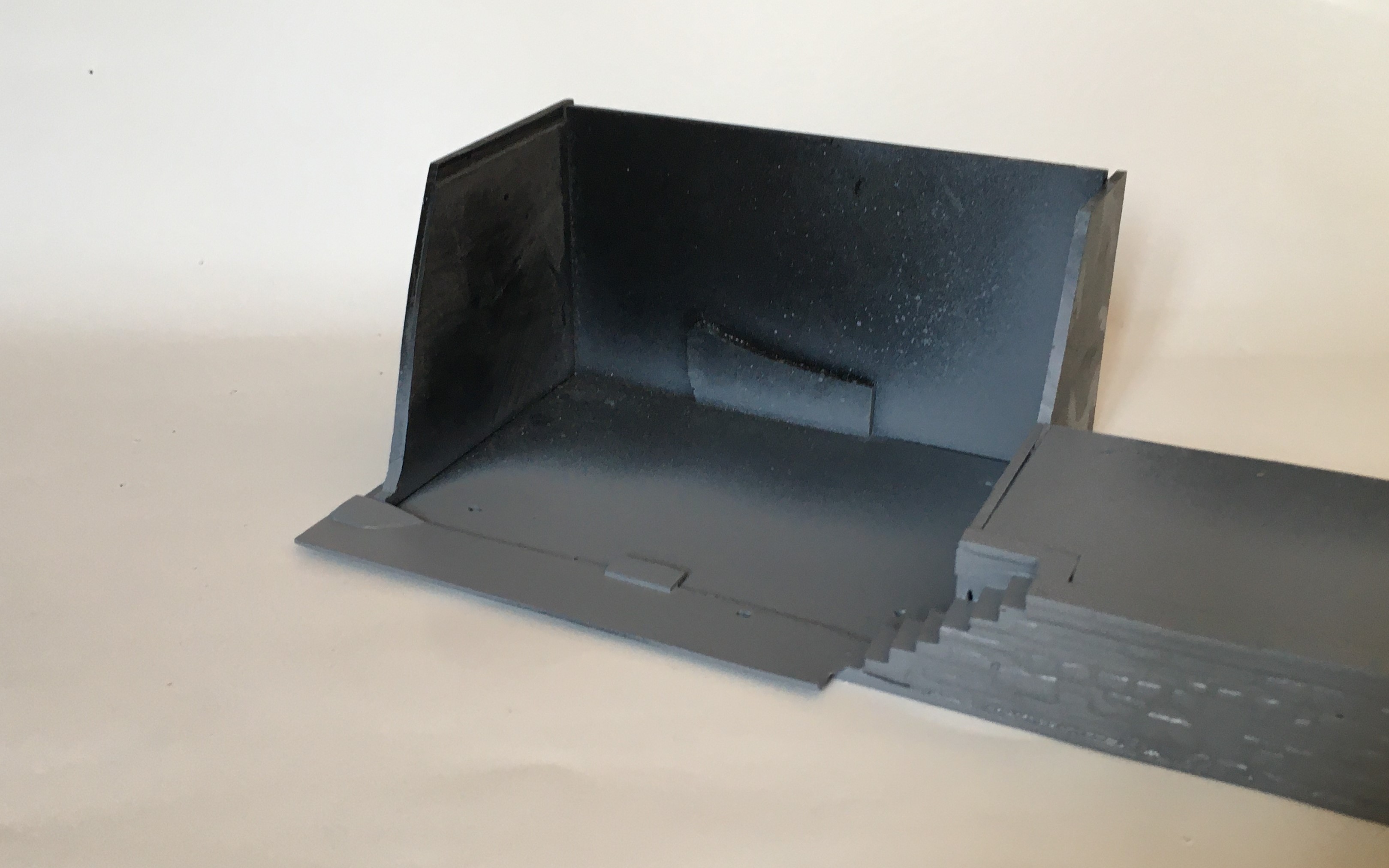
The large water tank is more prominent as it is located closer to the baseboard edge and is to the rear of the main focus of the MPD area, the trackwork between the shed and the turntable. It is also adjacent to the coaling bank and as a result I decided to make this now and as part of the base for the water tank.
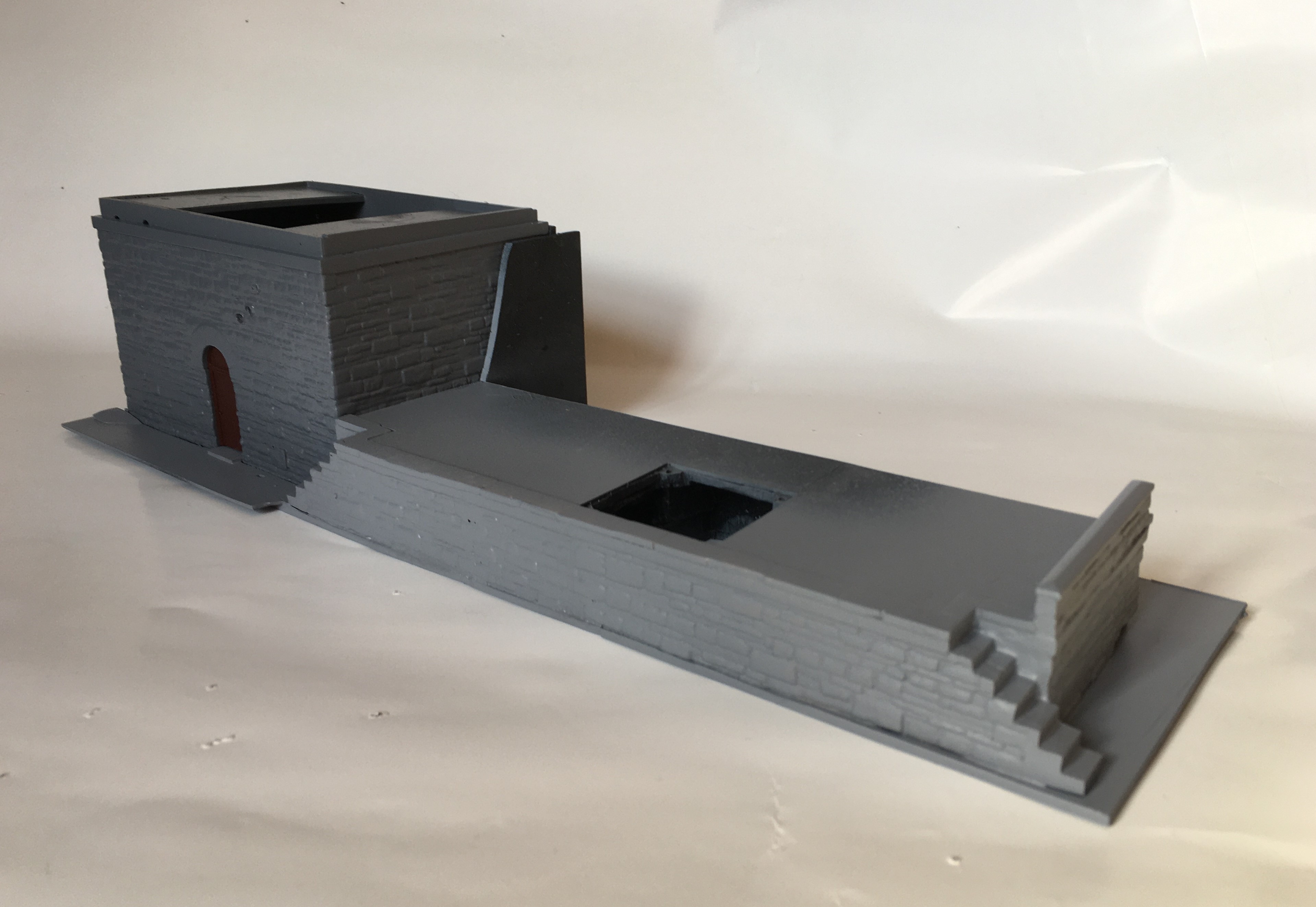
The smaller of the water tanks is designed to mask a baseboard joint in a rockface/embankment. The base (below) will thus be split into two halves when it is fitted, each sitting on adjacent boards – a neat way of not having the San Andreas fault line running through a rock face!
I have also started the painting of these, which had a fairly characteristic design with the border in a red/brown and a cream central panel. It is important to recreate this and as it is fairly eye catching, errors will be instantly visible.
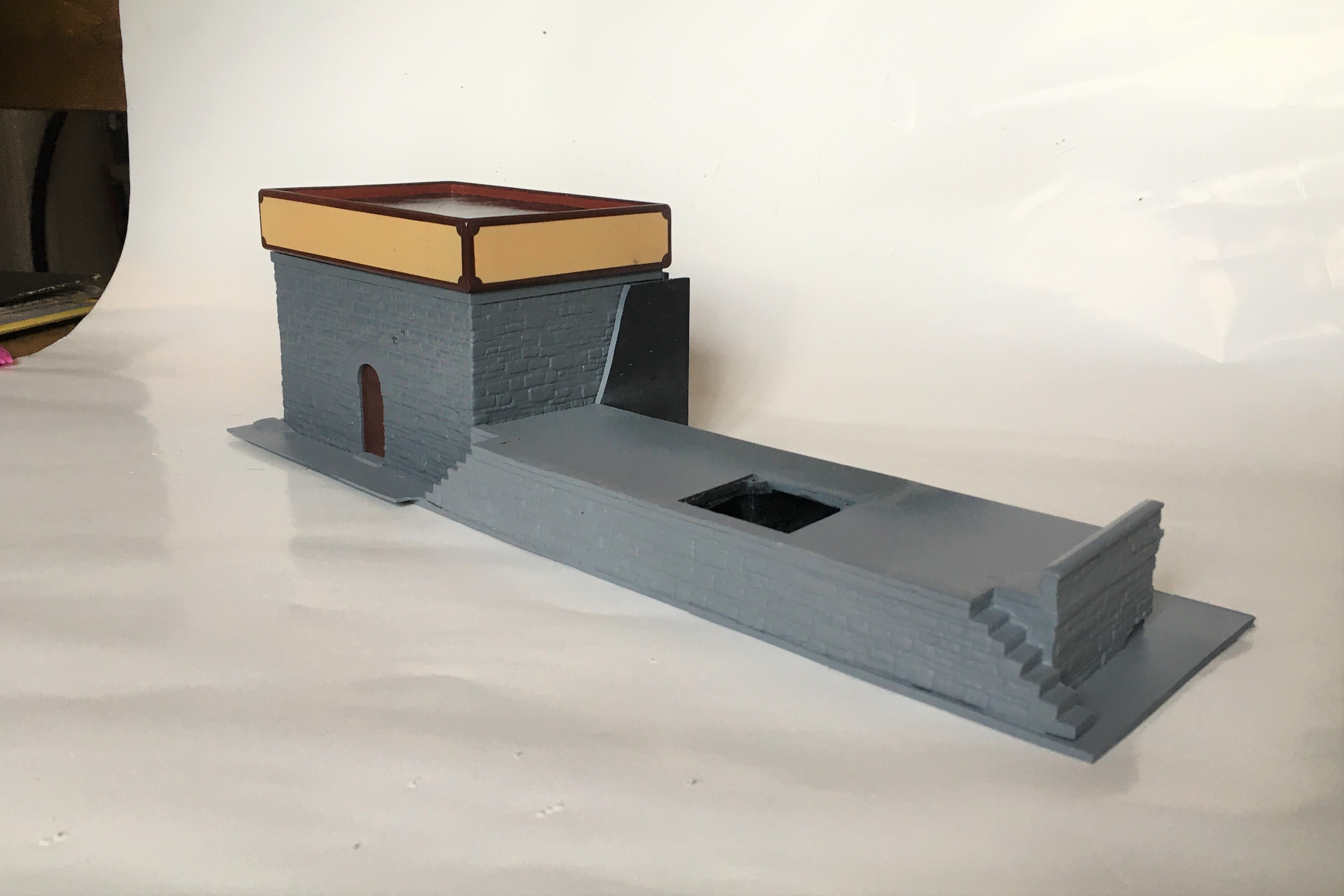
The straight edges weren’t too difficult to achieve with masking tape; initially the horizontals and then the verticals a day later. Peeling back the masking tape was a thrill to see if it worked!
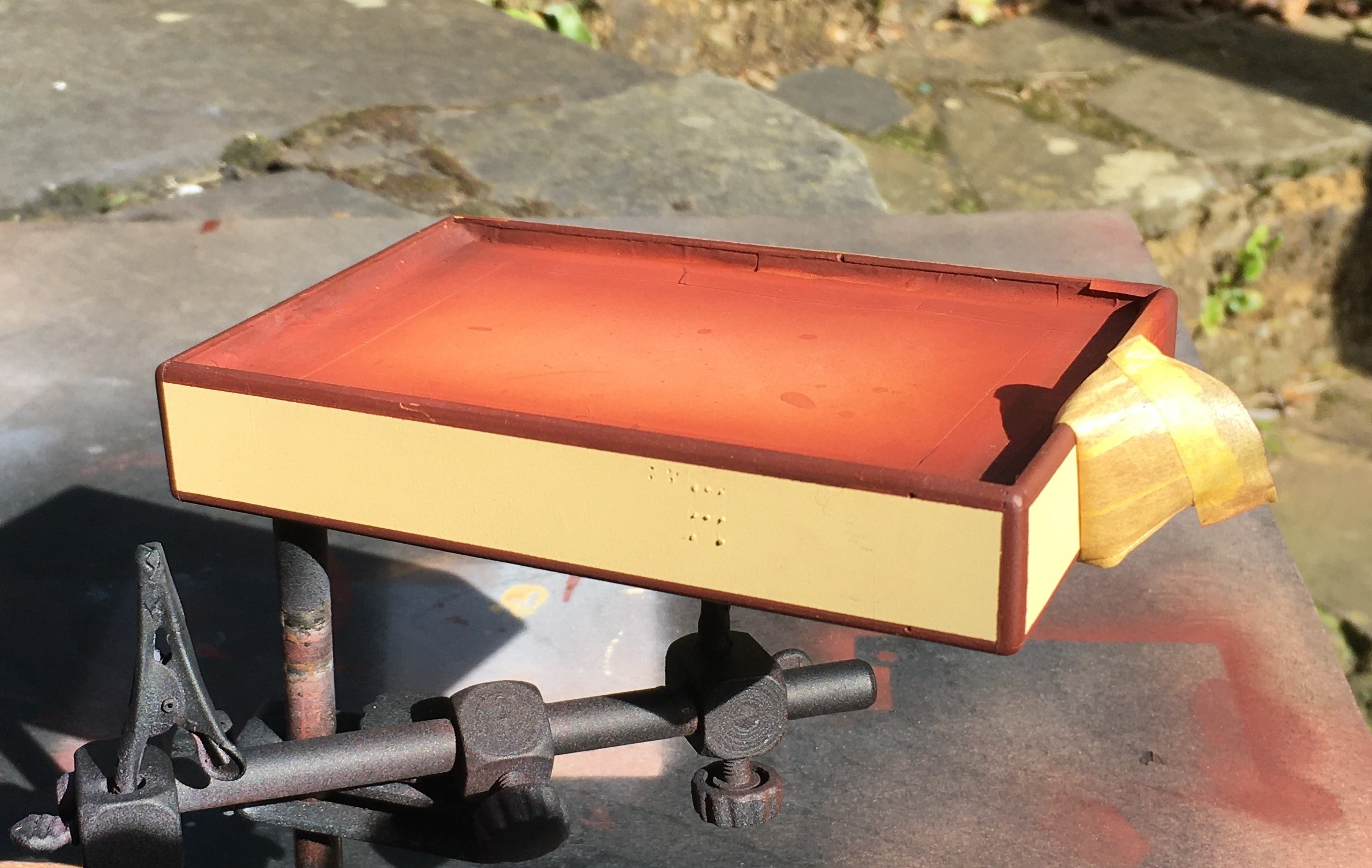
The scrolls at the corner was a concern throughout the construction of the water tanks but I did hit on an idea I think is rather nifty. I sprayed the same red/brown on some transfer paper (thanks Chris!) and once it was dry, used a domestic hole punch to create disks of transfer. I then cut them into segments that were a bit bigger than a quarter of the disk. They were then applied as a transfer to each corner.
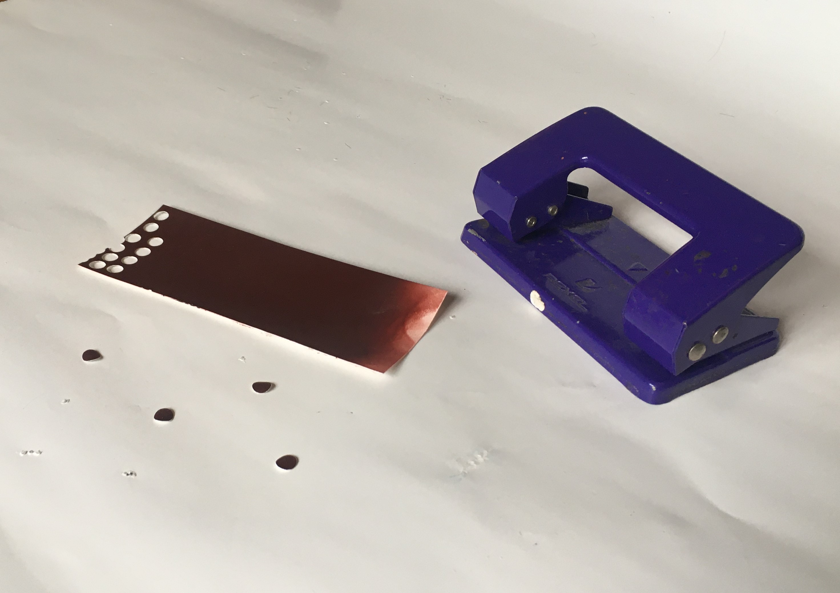
Actually, it was pretty easy once I got going – I definitely spent longer thinking about it than I did doing it! I am pretty pleased with the outcome, much neater than my hand could manage!
The rather prominent hole in the coal bank will be the subject of a future post, as there is something a bit different planned for this!
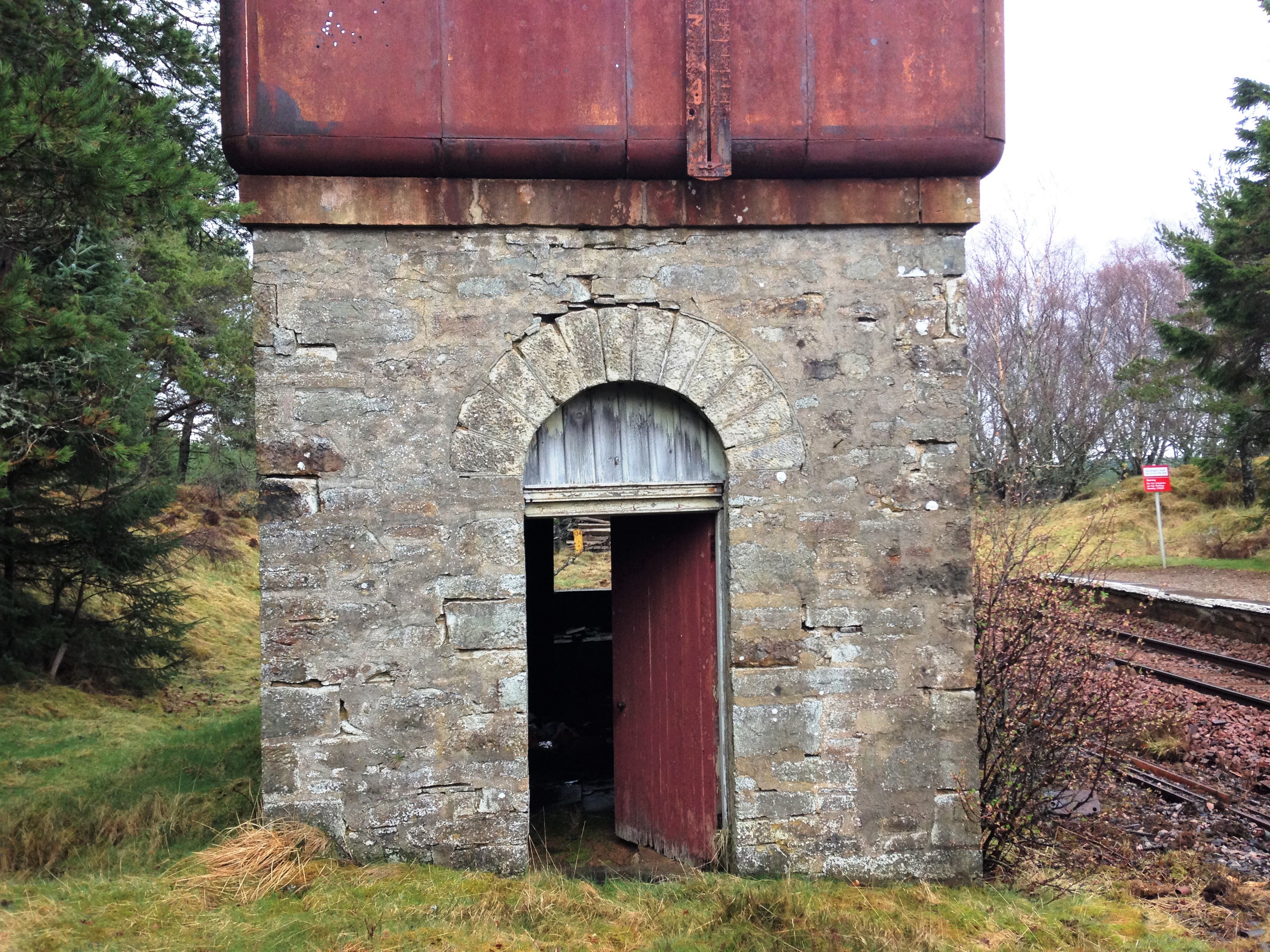
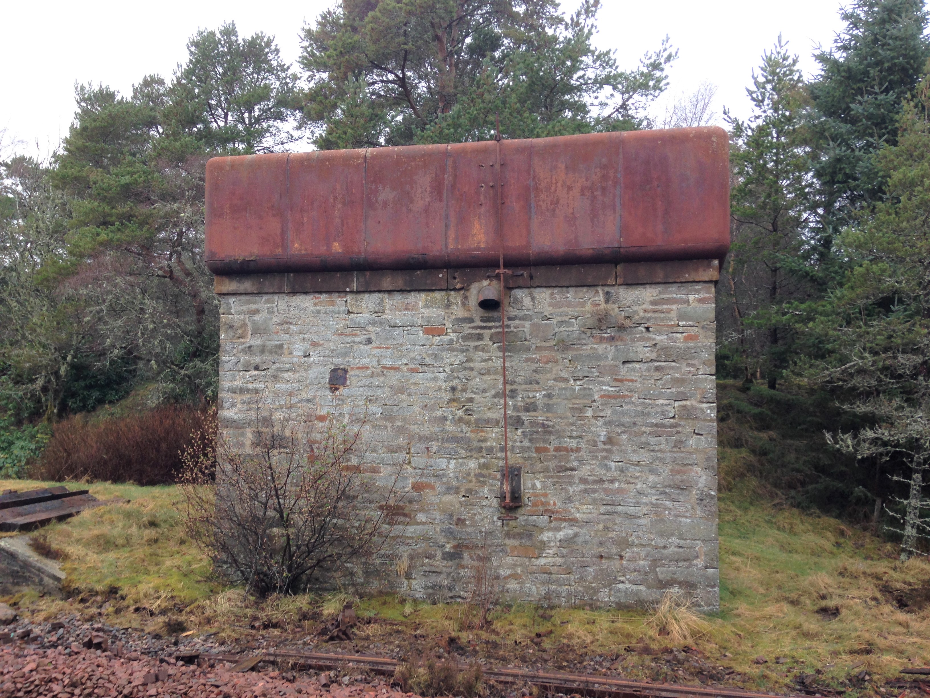
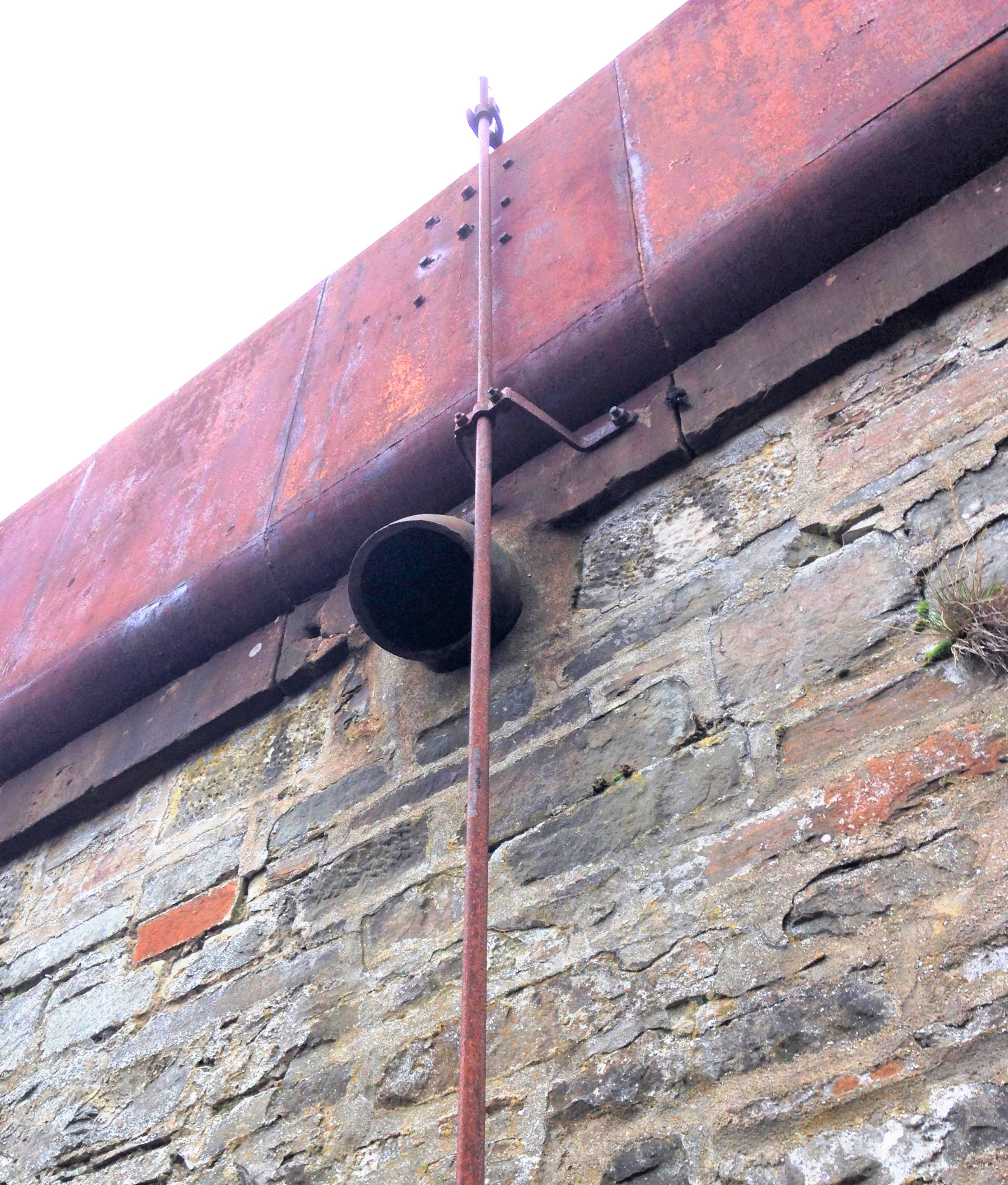
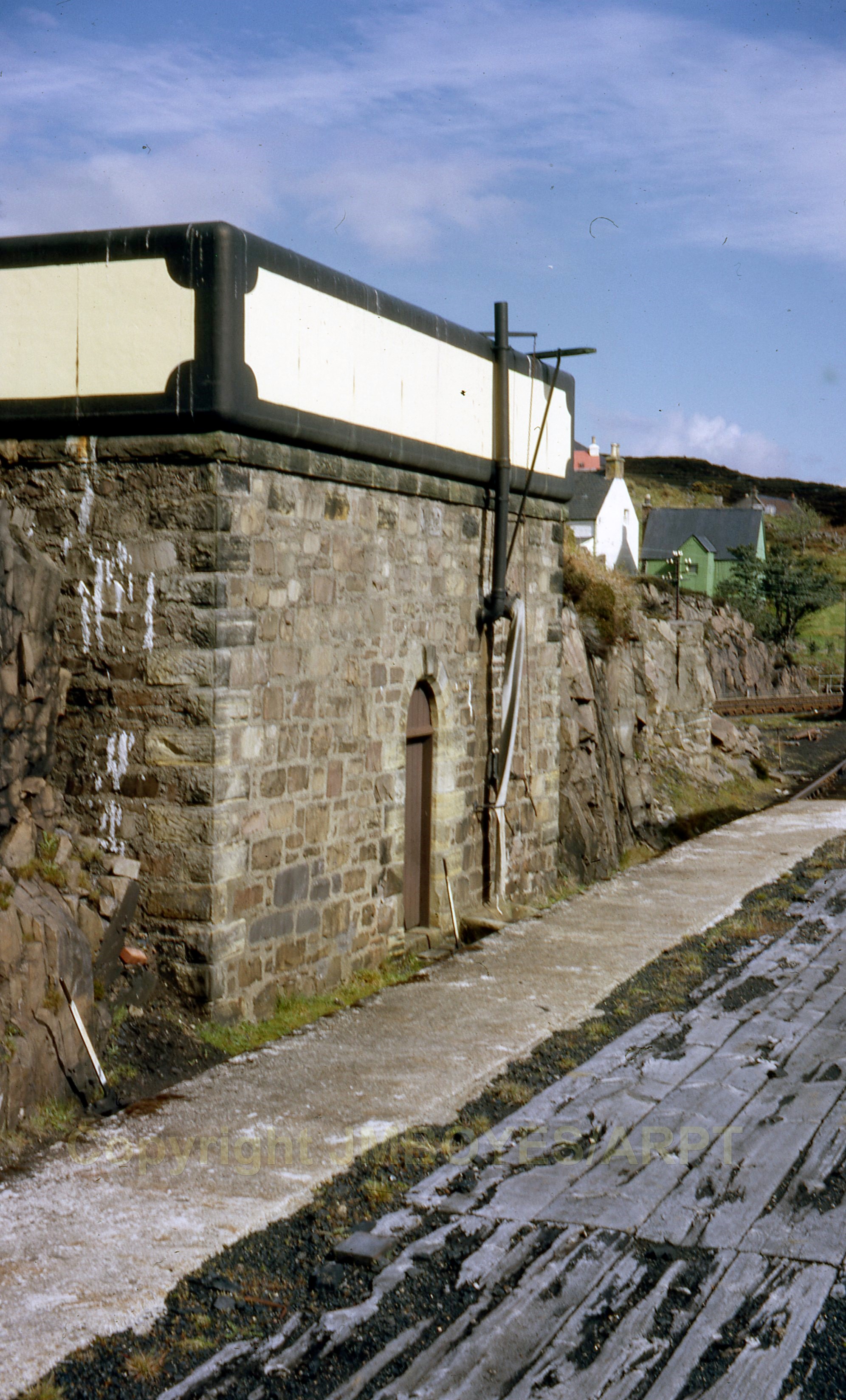
Alnabreac Water Tower – the Prototype
The smaller of the two water towers I am building is a model of the tower that the Highland Railway built at Altnabreac. Altnabreac is around 12 miles from the nearest paved road so even though it has not been used for approaching 60 years, it has proved too expensive to realise its scrap vale.
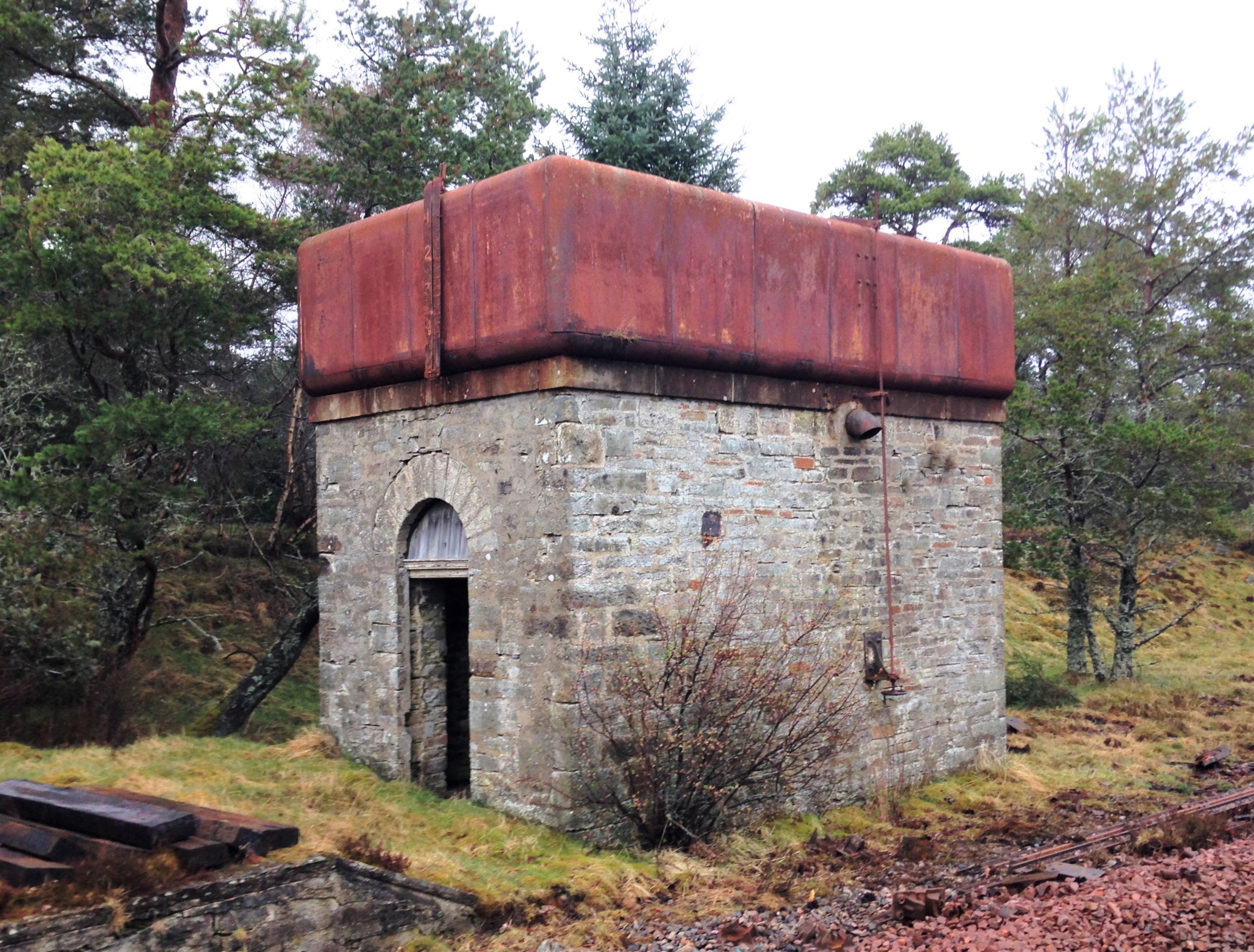
What is possibly even more remarkable, you can see the paint – including the detailing at the corners – which probably dates from the LMS era; how much original pre-1948 paint is still out there?
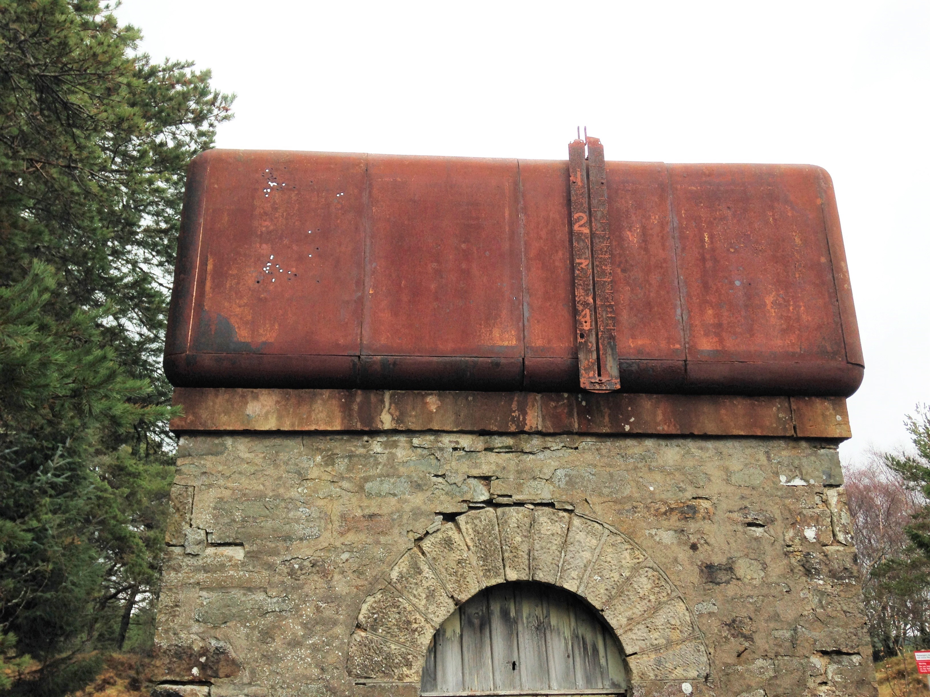
Being able to get up close to the tank, it can be seen that it is made out of sections; there are quarter segments for the corners and then straight panels for the sides. They obviously came as a kit of parts and could be built to a size to suit the requirement. Thus, I note that the Altnabreac is the same width wide as the Kyle tank was deep – so I can determine how many panels were used to make the Kyle version. Whilst the lines are fient, they are there and I will replicate them with a hint of a score on the plasticard.
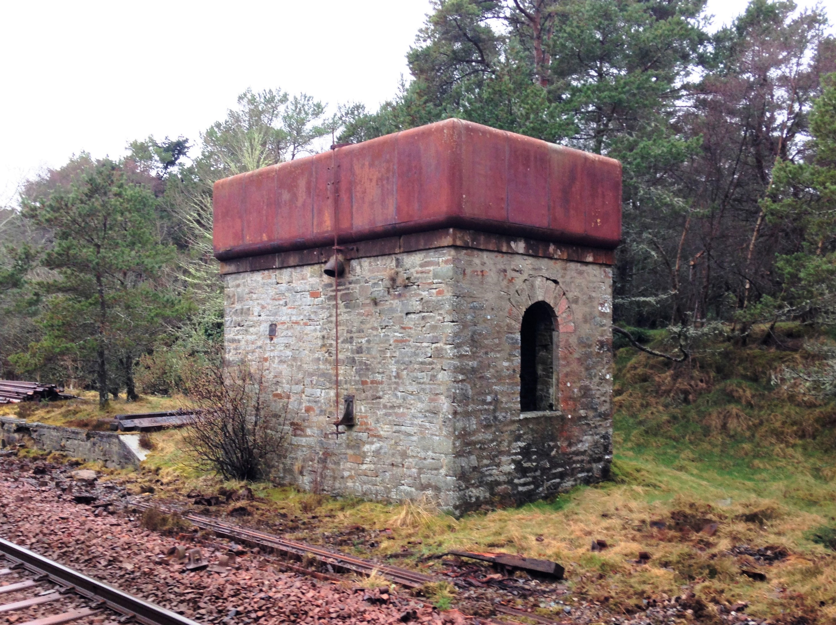
A float inside the tank was used to transmit the water level to this gauge on the exterior.
The tank as a whole is remarkably intact – the only elements I can positively identify is missing is the delivery bag which will have been of hessian and the wooden windows. However, I suspect there are two other elements that have now been removed. There was probably an access ladder at one end to reach the interior of the tank but leaving it in situ would to be dangerous, hence its removal. Furthermore, there is no sign of any heating to the tank. Whilst the largish body of water will have taken a while to freeze, the region around Altnabreac is well-known for its cold temperatures so I suspect there is a boiler inside with a flue through the tank. The outlet valve is controlled by a wheel at low level connected with a rod with a thread at its head. This connects to one end of a lever that has a threaded nut in order to transfer the movement into the interior of the tank where the valve is located.
A drawing of the water tank can be found at this link: Altnabreac Water Tower or if you are a member of the Highland Railway Society it will be in the next Journal and subsequently from their drawing service.
The other water tank I am building is a model of Kyle of Lochalsh’s water tank. Eddie Bellis drew this and his drawing is in the November 1975 edition of the Railway Modeller. There are couple of pictures of in LMS Engine Sheds: Volume 6 by the Oxford Publishing Co. The only other Highland Railway water tower that has been drawn that I know of is Garves, which Henry Orbach drew – it is in a 1950s Model Railway Constructor or was reprinted in my fathers The Dingwall & Skye Railway.

Let there be water……..part 1
Part of the concept of the back-story for Glenmutchkin is that it is at the end of a long line so that locos need to be serviced and it was also at the foot of a steep gradient, so trains need to be banked out of the station. All this is creates a lot of thirsty locomotives that would have needed servicing and attention – so it will have a busy motive power depot.
The Highland Railway’s water tanks tended to be of a similar style with a tank made of sectional components and rounded head, base and corners. There is nothing available from any of the manufacturers so it was obvious these need to be scratchbuilt.
There remains one tank of this type still in situ, at Altnabreac which I will describe in the next post. In addition to this, there are drawings from Eddie Bellis of the Kyle’s water tower and also of Garve by Henry Orbach. I have elected to build a pair – one of Kyle and one of Altnabreac (the latter being the smaller).
Kyle’s water tank from the early post steam era. Photograph with permission from Armstrong Railway Photographic Trust, JM Boyes collection.
Starting with the tanks, I laminated a series of strips of plasticard to the right height and then used a belt sander to put the chamfer on these before then making them up into a box.
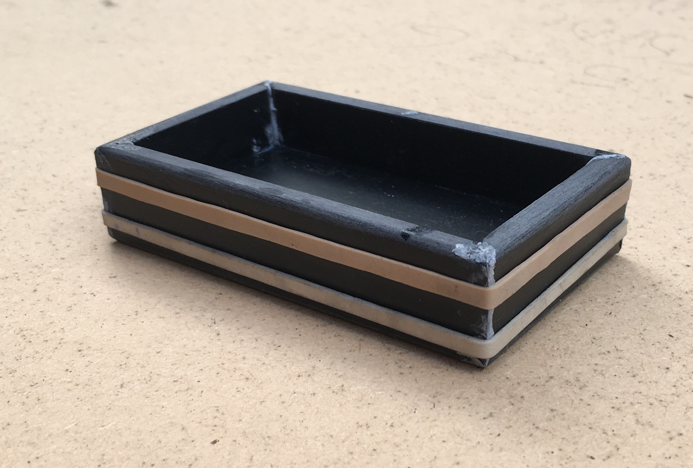
As with most of my stone buildings, I use Wills random stone plastic sheets; now available from Peco. On far too many occasions I see this used with panels butted against each other; either on corners or even worse on the flat. Unless the stones are toothed into each other, this screams as being incorrect even to a layman. Therefore, it is best to form corners either from a sheet cut vertically and then chamfer the inside faces so that the coursing is retained for its full length even on the cut face.
This means that courses line up from side to front without any silly jumps, as can be seen below. This technique can not be used in all examples and sometimes it is necessary to actually tooth panels into each other by cutting corresponding dog teeth into adjacent panels.
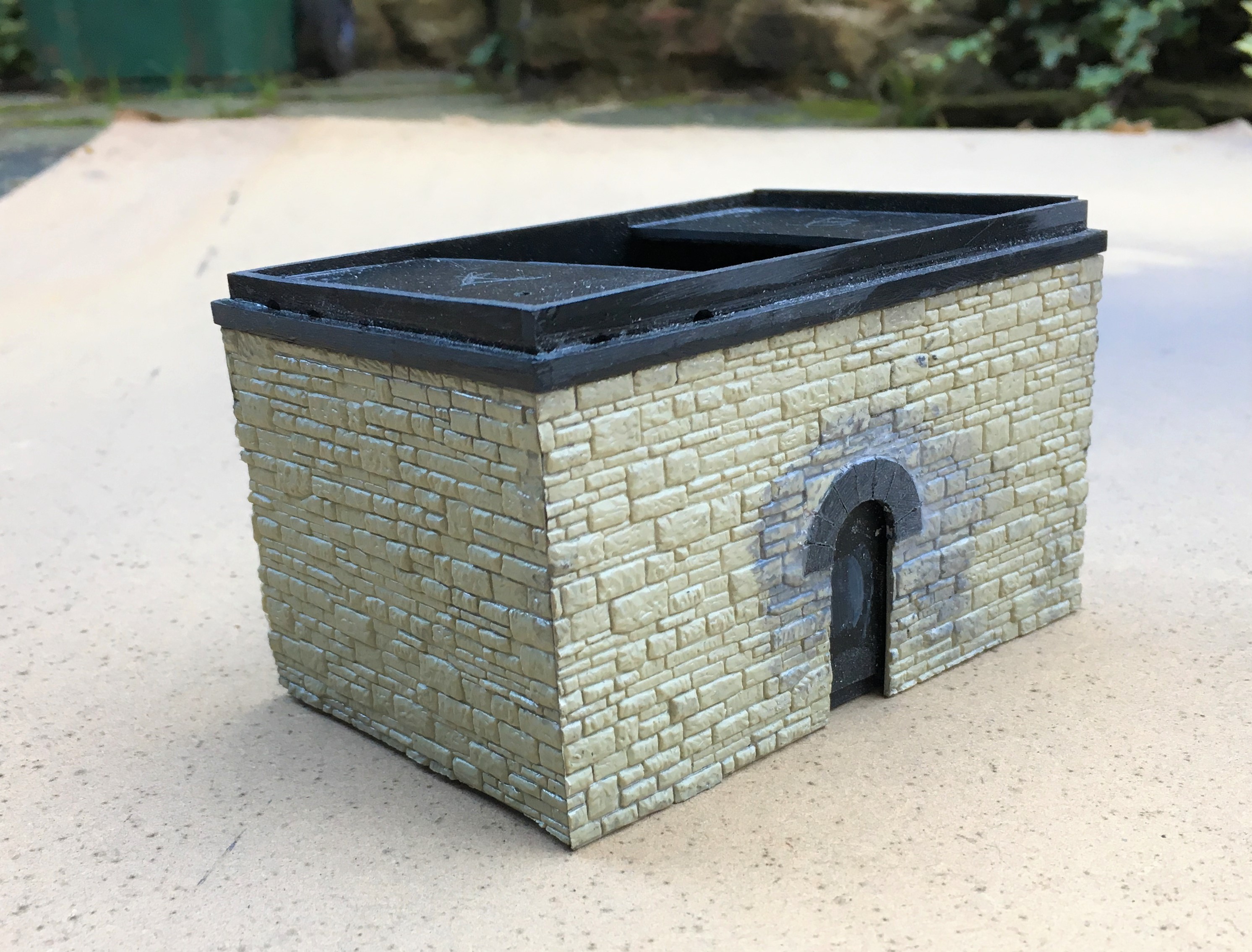
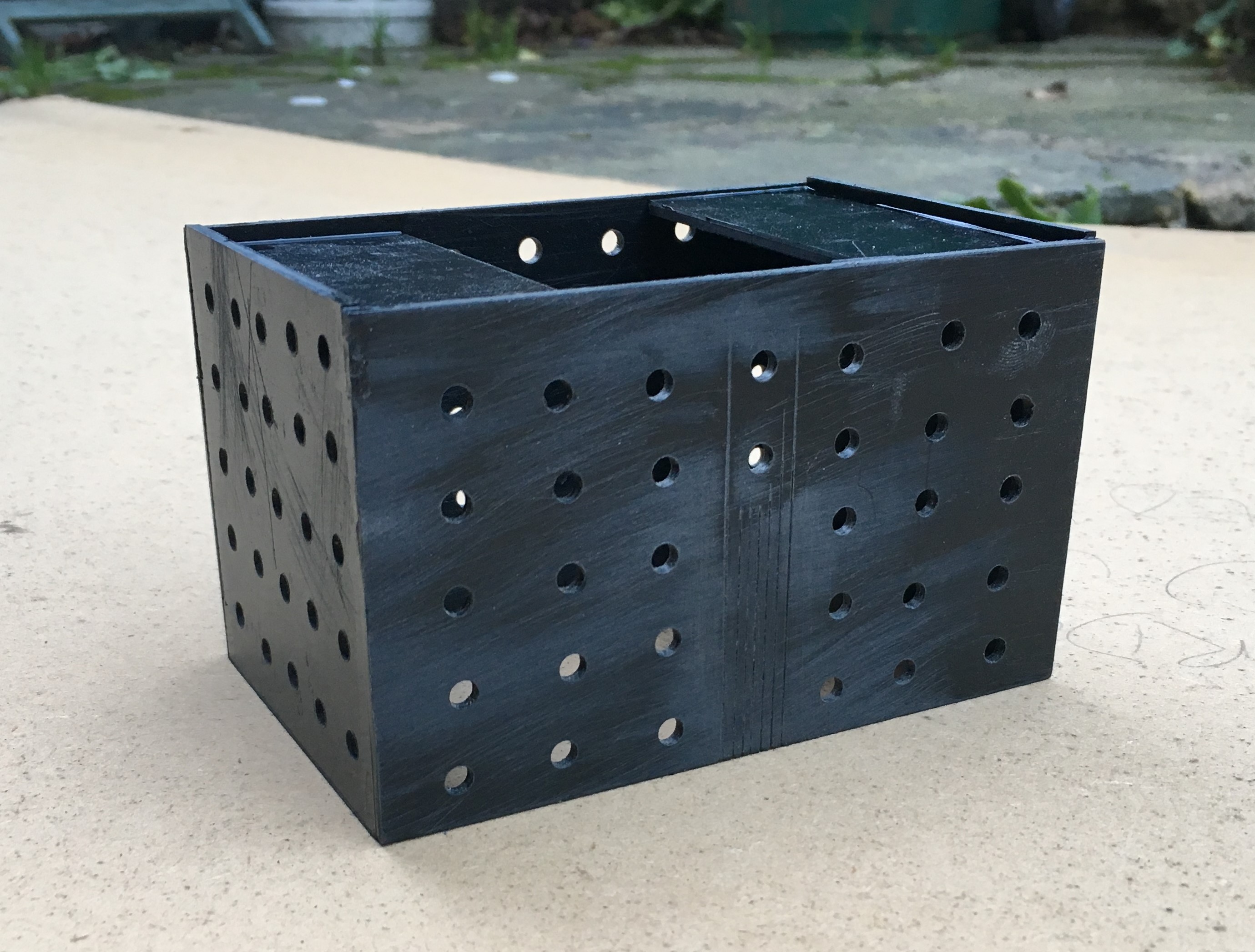
I find that the mortar courses on Wills sheets are a bit too deep and because lots of others use it its pattern is a little too obvious; so it looses its realism (or maybe I am just so sad that I can tell a material by its stone coursing!!). I get over this by part filling the mortar courses with a plastic filler – which is basically dissolved plastic in a solvent carrier (lovely and smely!). This tends to distort the sheets as it is only applied to one side so I first laminate the sheet to some thick (1.5 or 2mm plasticard). Due to the volumes of solvent to be sloshed around in constructing buildings in this manner, it is important to allow for the solvent to escape – regretfully I have a number of coach roofs which many years later have mushy sections where the solvent has been trapped and has distorted the plastic in its efforts to cut through it and escape! I thus drill regular holes or slots in the backing plasticard, which you can see here:
Whilst the desire to mask the coursing pattern on the Wills sheet might seem a fair amount of bother given the need to reinforce the walls with an inner laimanate, I think the effect is worth the effort. A blast of grey primer shows that the coursing and texture of the stone is retained but equaly it does not look like everyone else’s!
The use of the laminations does give the advantage that slots for window frames and doors can be created. These allow an etching to be slid in, either from below or behind. They can be slid out again for painting and make this aspect a breeze to do.
And this is where they have got to; the guts of both done but with a chunk of detailing and some basework still to be done.
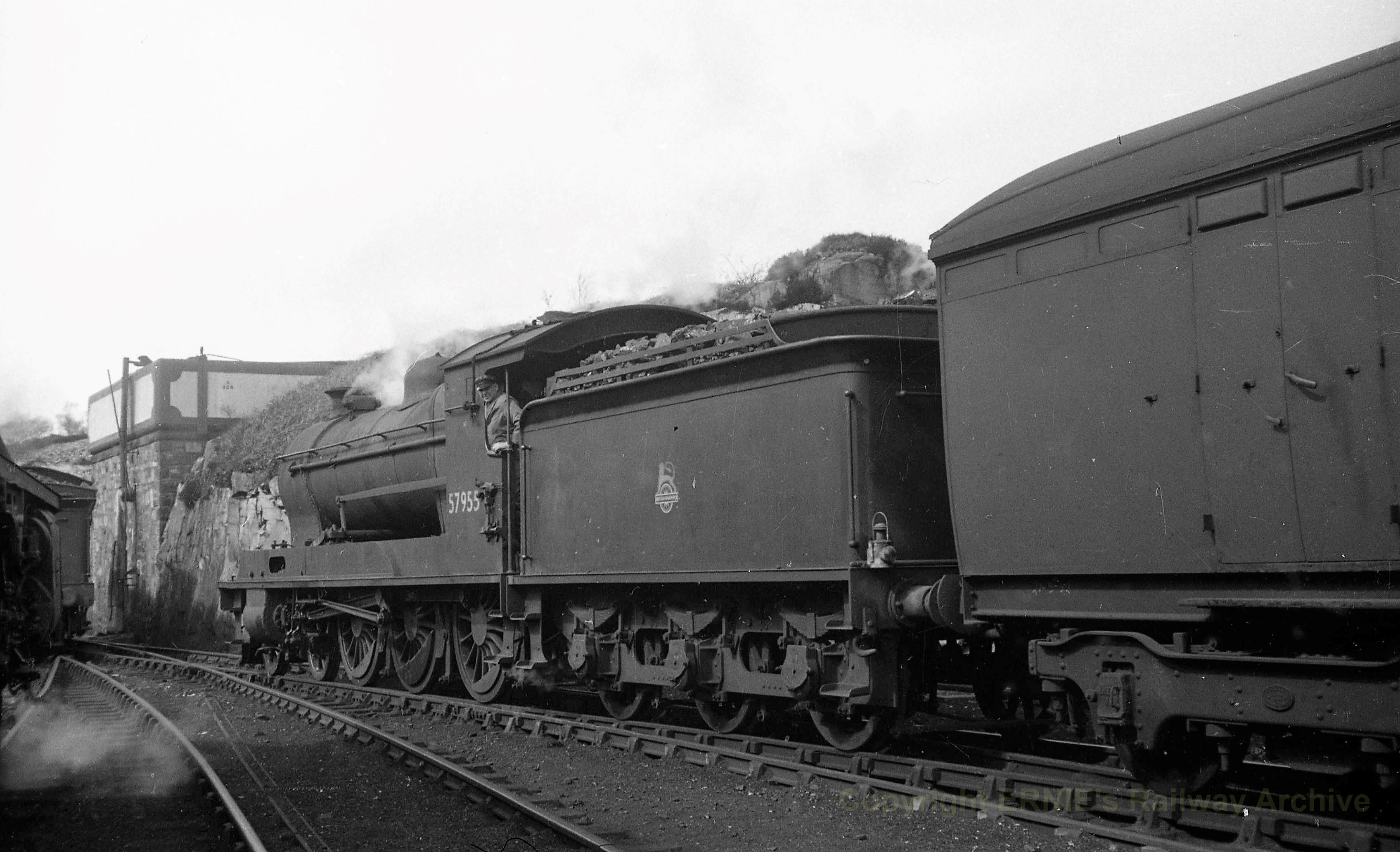
But lets sign this post off with a fine HC Casserley picture of a Superheated Goods using the MPD as a headshunt in the early 1950s. This photograph is used with permission and is now part of Ernie Brack’s collection. He has a substantial on line collection of photographs (including the JM Boyes collection) with a good proportion of them being of the Highland’s system – you can loose many an hour in his flickr site – this being a link to his Dingwall & Skye album.