Blog Archives

Fuel for Thought
Obviously, where there is water in a locomotive yard, there really ought to be coal too.
The Highland, like many other railway companies of the time (certainly the Scottish ones), sought to stockpile coal. This was presumably insurance against coal strikes and allowed them to purchase coal at times when the price was favourable. Thus, quite substantial coal stacks where very much a feature of shed areas in the pre-grouping era. Typically, these were arranged in engineered stacks, with the sides formed in “dry-coal walling” and then loose coal behind. I can’t recall ever seeing this modelled, so I though I would change that!
The actual structure of the loading bank was formed in plasticard and Wills random stone sheets, but with the mortar courses softened as I described for the water towers. The shape of the coal stack was formed with a piece of house insulation left over from a DIY job and then real coal used to form the effect of…..err……real coal. Actually, real coal does not look quite like real coal without a bit of effort. It does shatter into angular but irregular lumps like real coal (especially if lignite coal is used) but its glossiness does not scale down. However, a vigorous brush with generous amounts of soot black weathering powder takes the gloss back and the whole becomes quite convincing. You do feel as if you are going to get pretty filthy if you go up onto the bank – and until the whole is fixed with matt varnish, you would!
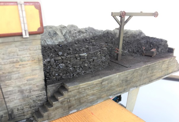
Individual coal chunks were glued in place to form the wall structure. To get the effect, it is not enough to simply scatter the coal onto a bed of glue each chunk has to be laid individually with care taken to lock it into the course below – just like a real dry stone wall. Thus, the vertical walls of this took about a day to complete, scattered over about 8 stints because it is necessary to let the glue dry after every couple of courses to stop the layers collapsing. It is then possible to scatter the loose material behind the walls onto a layer of glue – the above picture shows the contrast in effects between the two methods.
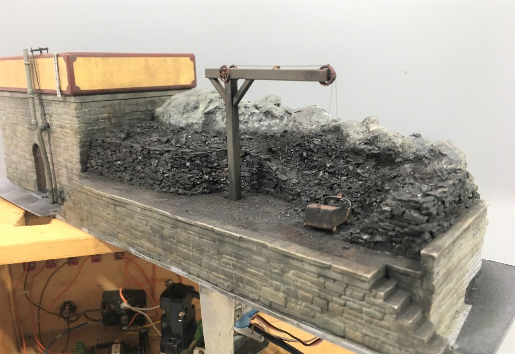
But it is hard work shovelling coal into tenders, especially as the locos got larger and their tenders higher. As befitting such an important place as Glenmutchkin, it has all the modern amenities for coaling engines, a hand crane and a large bucket! In this case, I have fitted servos to this so that it operates – partly as a bit of fun and also to slow things down in the yard to a more realistic pace without it getting too boring for the viewer.
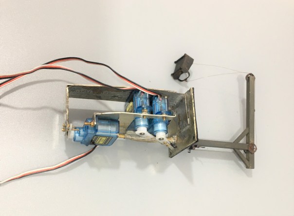
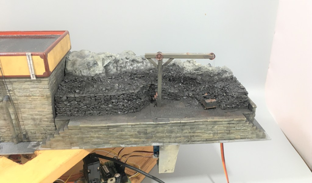
The crane operation was achieved by way of three servos – one to rotate it and then one each for the front and rear of the coal bucket. These are all mounted onto a cradle that is rotated by the former – thus as the crane rotates so too do all the servos and there is a quadrant shaped slot in the base to the rear of the post (just visible in the picture above) that allows the cables to rotate too without snagging.
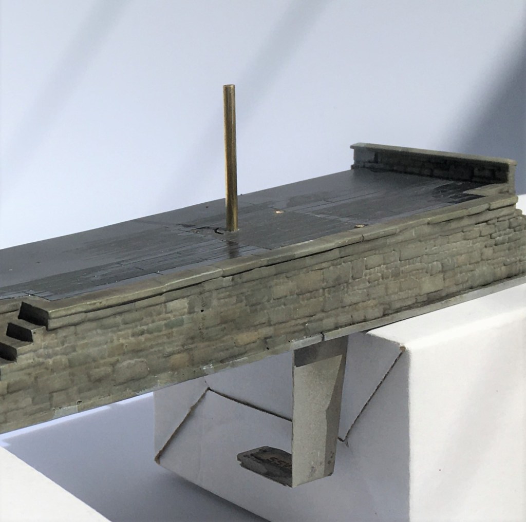
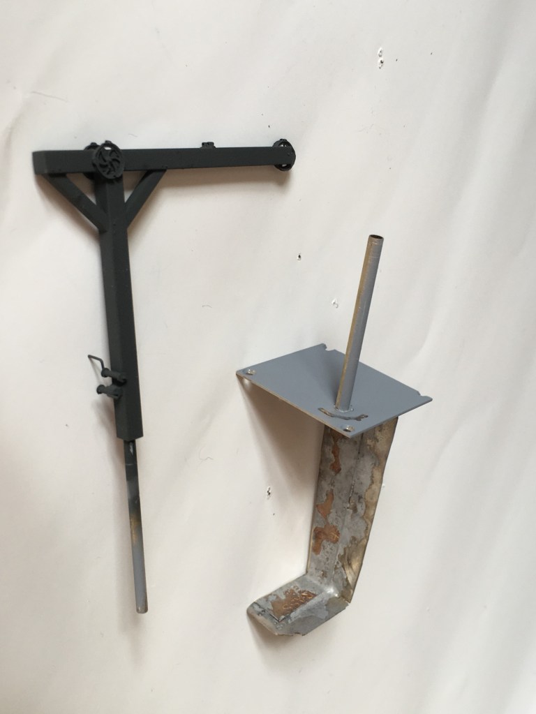
The cradle is mounted to a solid rod that is in turn secured to the actual crane. This then slides into the rod that can be seen projecting from the base in the picture above. This means that there is limited strain on the crane or the mount as I had feared it might otherwise snap with any heavy-handedness on my part (something I am prone to!). The rest of the crane was made with brass hollow section and pulley wheels from Bill Bedford. A series of guides were made of small section tube on the pulley wheels, at the winding drum and across the jib to retain the operating cables.
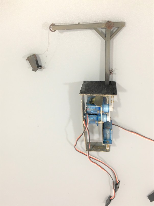
The bucket was fashioned from metal sheet and is filled with low melt solder to give it as much weight as possible. It is secured to the servo arms with invisible thread – which is a nylon seamstresses material used for making invisible stitches. It comes in both clear (which really is invisible) and black, I used the latter. It is much better than cotton thread as that has a furry finish that looks terrible after a time or if it is painted. It is, however, very fine and rather wriggly to knot, so using it involves a certain amount of cussing!
And this is what it looks like in operation…………
A little of the bouncing about of the bucket is caused by it sitting on my servo test rig, so the act of changing the switches imparts a little vibration. Hopefully, when mounted on the layout this will be less obvious.
I do still need to do the final detailing on this; tools, a bit of discarded debris and a couple of fellas from Modelu standing around doing nothing (because static people in animated poses look silly on a model layout!).

Let there be water……..part 1
Part of the concept of the back-story for Glenmutchkin is that it is at the end of a long line so that locos need to be serviced and it was also at the foot of a steep gradient, so trains need to be banked out of the station. All this is creates a lot of thirsty locomotives that would have needed servicing and attention – so it will have a busy motive power depot.
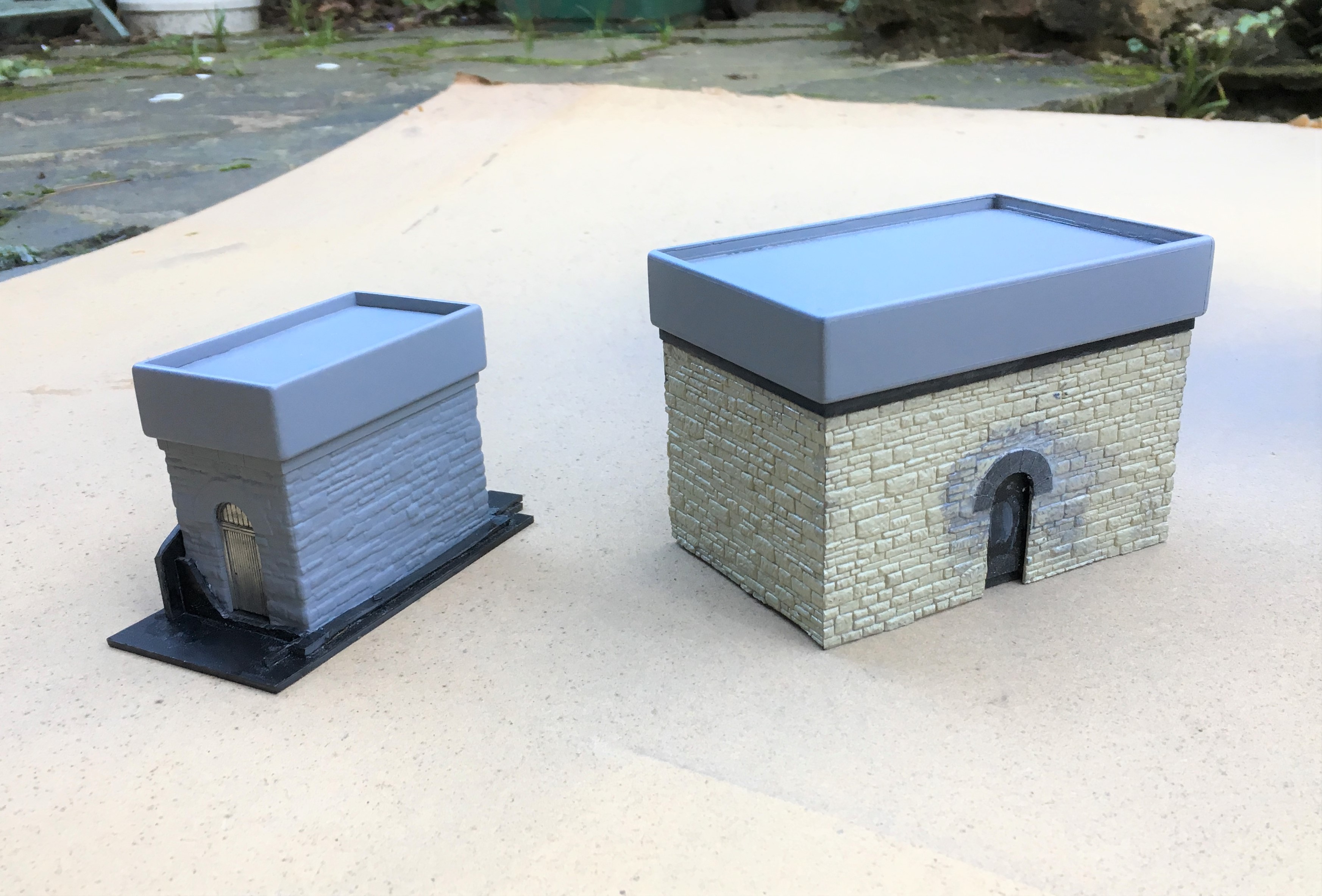
The Highland Railway’s water tanks tended to be of a similar style with a tank made of sectional components and rounded head, base and corners. There is nothing available from any of the manufacturers so it was obvious these need to be scratchbuilt.
There remains one tank of this type still in situ, at Altnabreac which I will describe in the next post. In addition to this, there are drawings from Eddie Bellis of the Kyle’s water tower and also of Garve by Henry Orbach. I have elected to build a pair – one of Kyle and one of Altnabreac (the latter being the smaller).
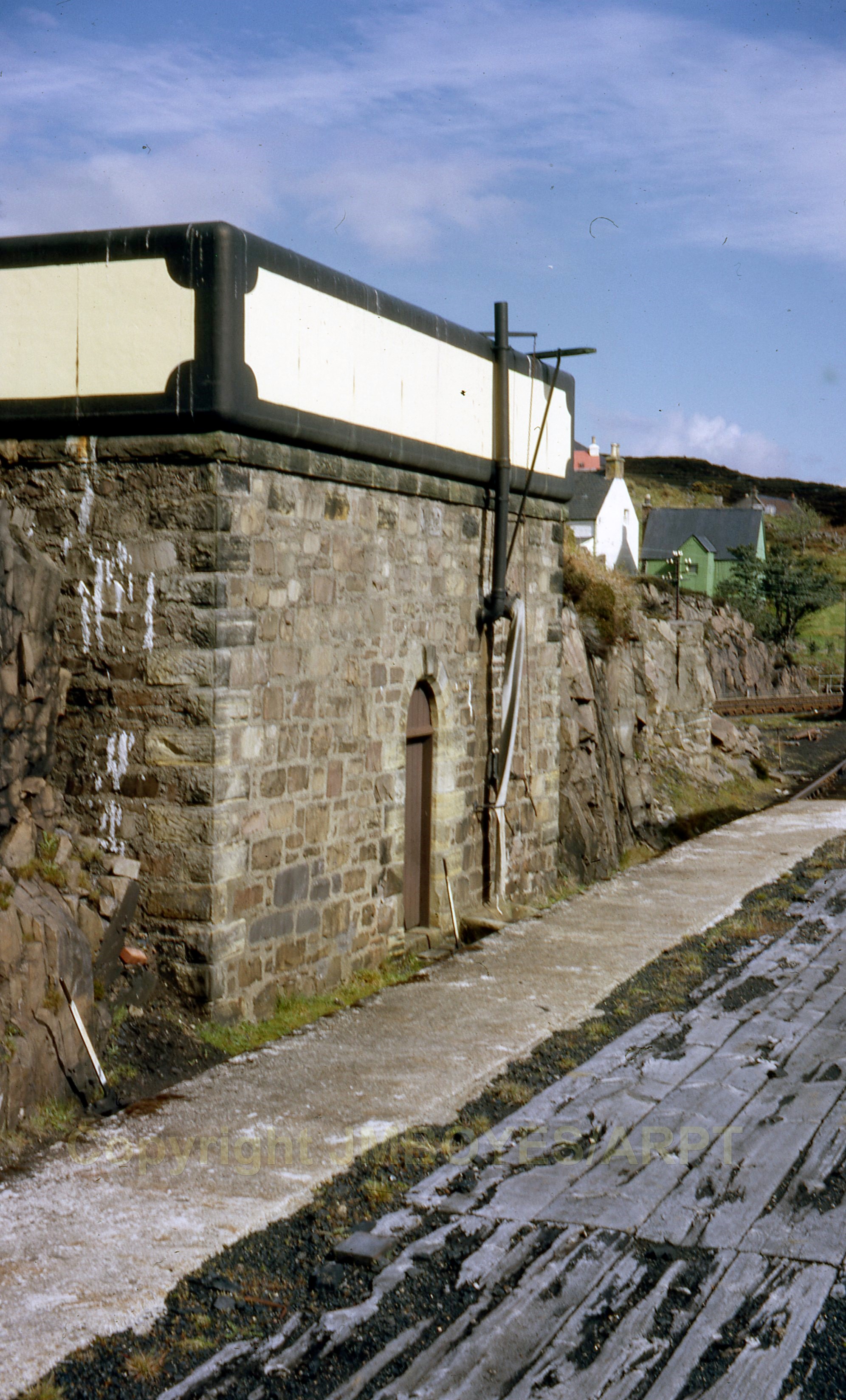
Kyle’s water tank from the early post steam era. Photograph with permission from Armstrong Railway Photographic Trust, JM Boyes collection.
Starting with the tanks, I laminated a series of strips of plasticard to the right height and then used a belt sander to put the chamfer on these before then making them up into a box.
As with most of my stone buildings, I use Wills random stone plastic sheets; now available from Peco. On far too many occasions I see this used with panels butted against each other; either on corners or even worse on the flat. Unless the stones are toothed into each other, this screams as being incorrect even to a layman. Therefore, it is best to form corners either from a sheet cut vertically and then chamfer the inside faces so that the coursing is retained for its full length even on the cut face.
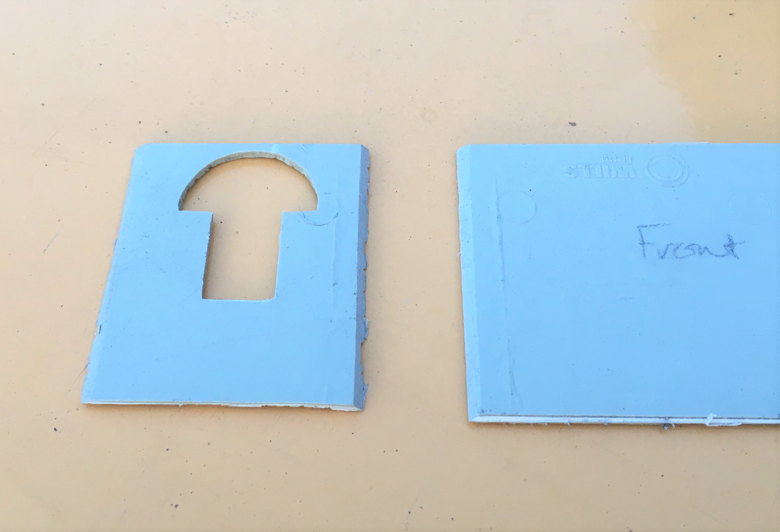
This means that courses line up from side to front without any silly jumps, as can be seen below. This technique can not be used in all examples and sometimes it is necessary to actually tooth panels into each other by cutting corresponding dog teeth into adjacent panels.
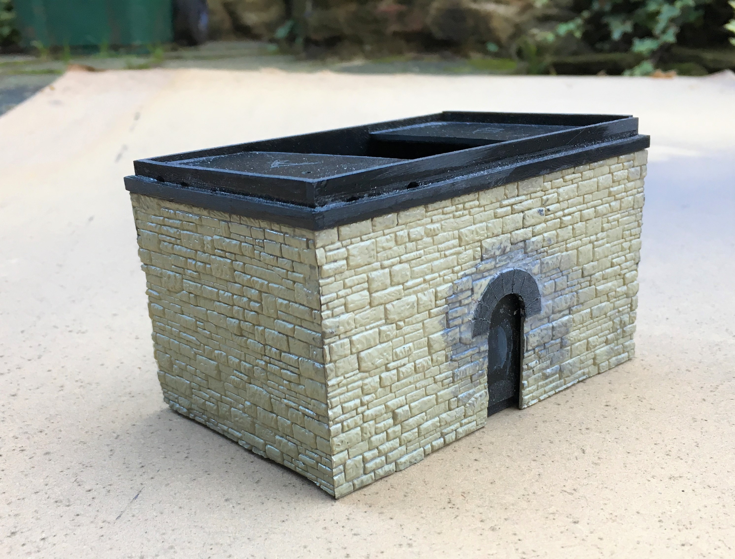
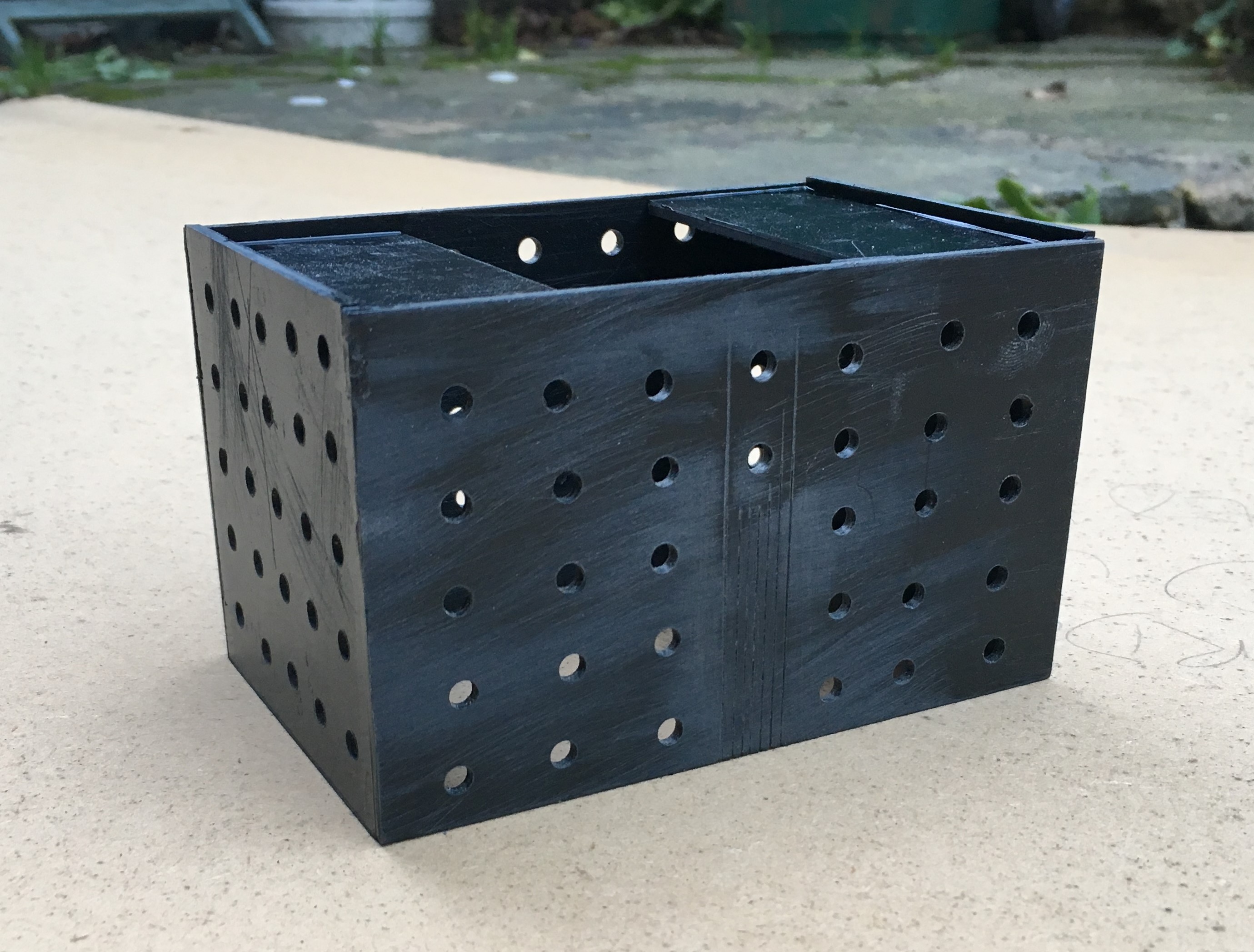
I find that the mortar courses on Wills sheets are a bit too deep and because lots of others use it its pattern is a little too obvious; so it looses its realism (or maybe I am just so sad that I can tell a material by its stone coursing!!). I get over this by part filling the mortar courses with a plastic filler – which is basically dissolved plastic in a solvent carrier (lovely and smely!). This tends to distort the sheets as it is only applied to one side so I first laminate the sheet to some thick (1.5 or 2mm plasticard). Due to the volumes of solvent to be sloshed around in constructing buildings in this manner, it is important to allow for the solvent to escape – regretfully I have a number of coach roofs which many years later have mushy sections where the solvent has been trapped and has distorted the plastic in its efforts to cut through it and escape! I thus drill regular holes or slots in the backing plasticard, which you can see here:
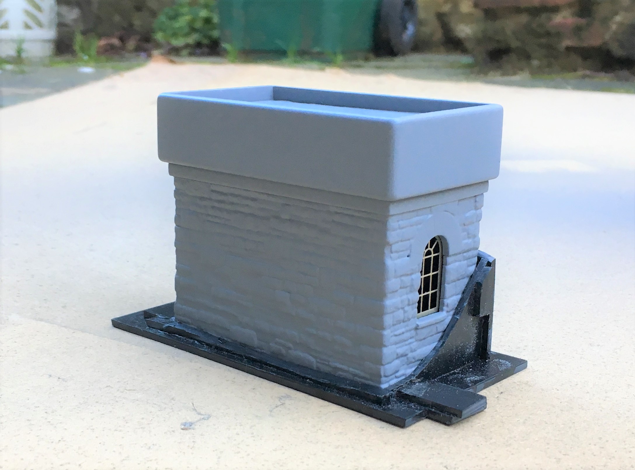
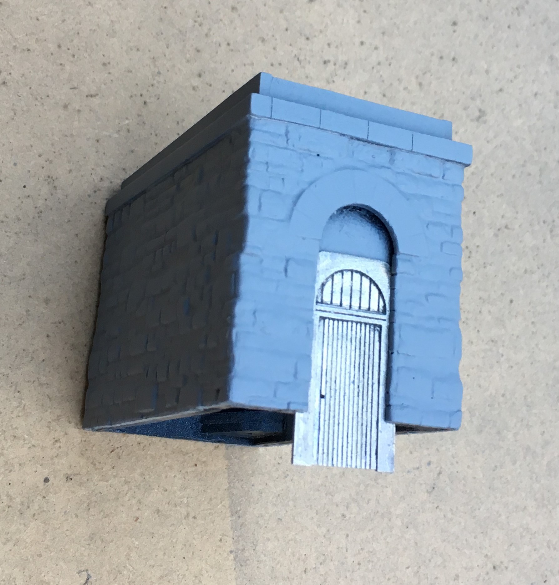
Whilst the desire to mask the coursing pattern on the Wills sheet might seem a fair amount of bother given the need to reinforce the walls with an inner laimanate, I think the effect is worth the effort. A blast of grey primer shows that the coursing and texture of the stone is retained but equaly it does not look like everyone else’s!
The use of the laminations does give the advantage that slots for window frames and doors can be created. These allow an etching to be slid in, either from below or behind. They can be slid out again for painting and make this aspect a breeze to do.
And this is where they have got to; the guts of both done but with a chunk of detailing and some basework still to be done.
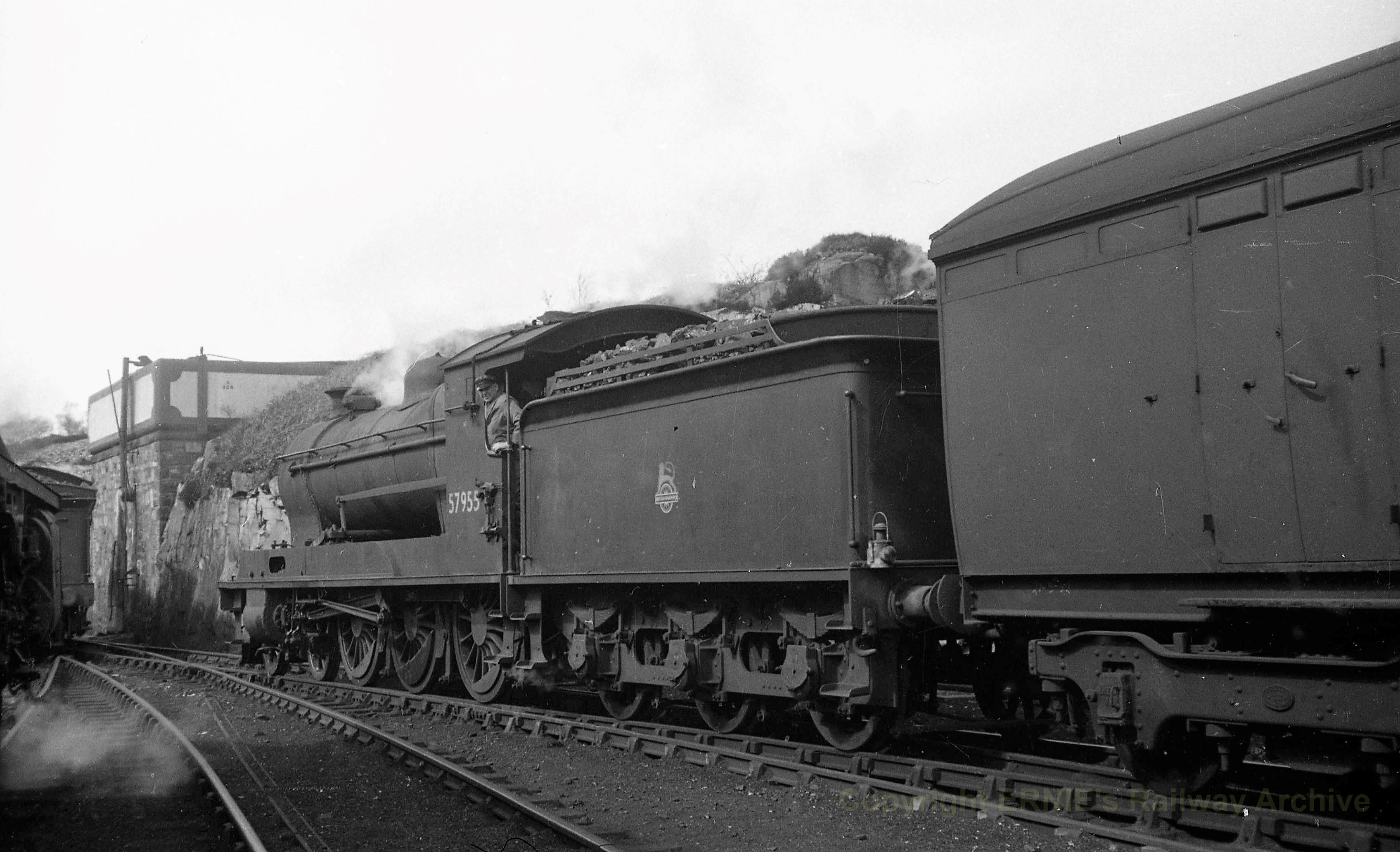
But lets sign this post off with a fine HC Casserley picture of a Superheated Goods using the MPD as a headshunt in the early 1950s. This photograph is used with permission and is now part of Ernie Brack’s collection. He has a substantial on line collection of photographs (including the JM Boyes collection) with a good proportion of them being of the Highland’s system – you can loose many an hour in his flickr site – this being a link to his Dingwall & Skye album.

That was the weekend that was….
Well the layout made it to and from Scaleforum – possibly I did too!
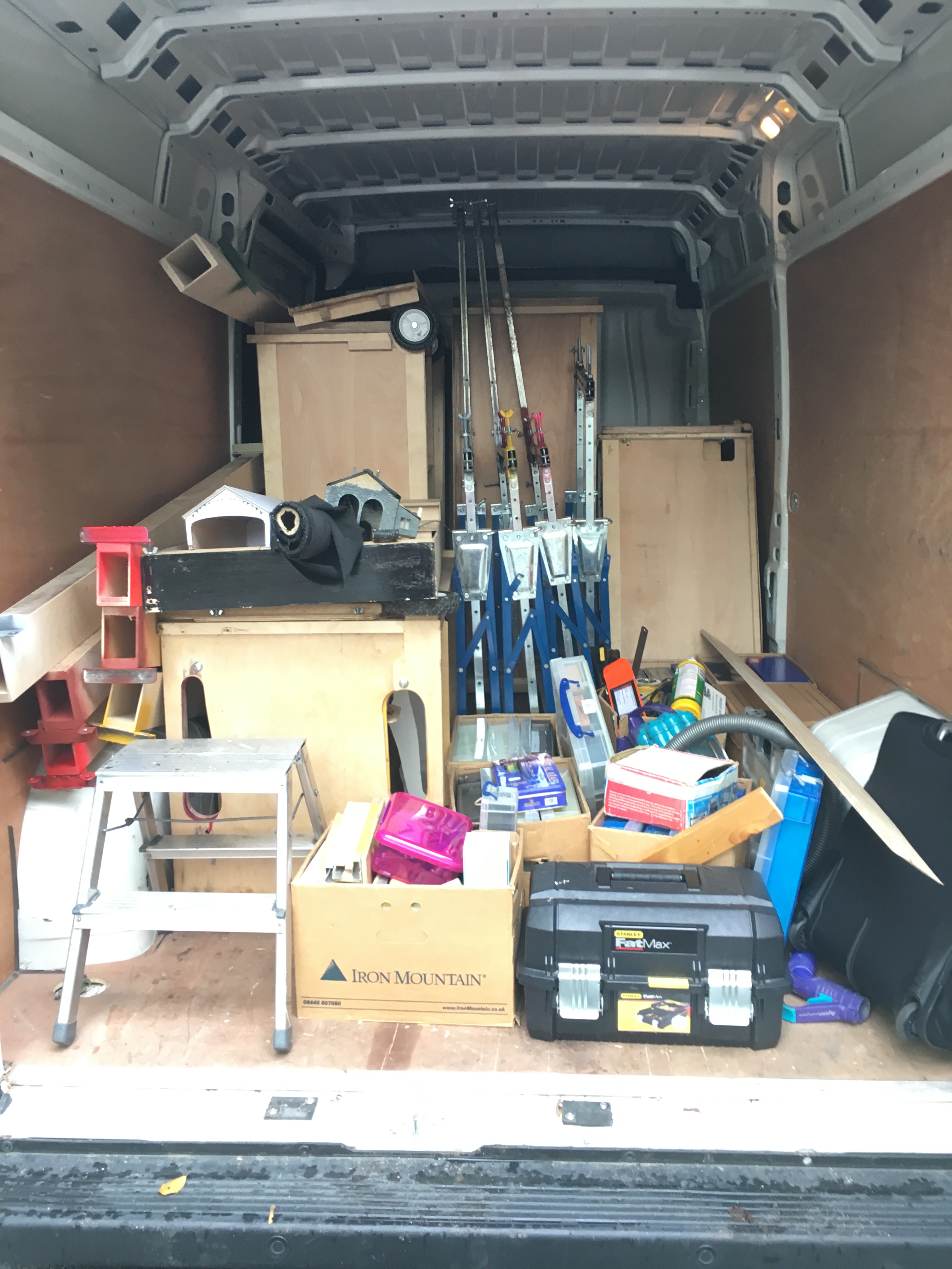
Last Friday, the inside of the hire van looked like this. Whilst the cases worked a treat, the dismantling of the layout from being set up on my own took a long time – much longer than I had hoped or expected.
Once at the venue, I was able to press gang some “volunteers” to erect the layout and this was much easier.
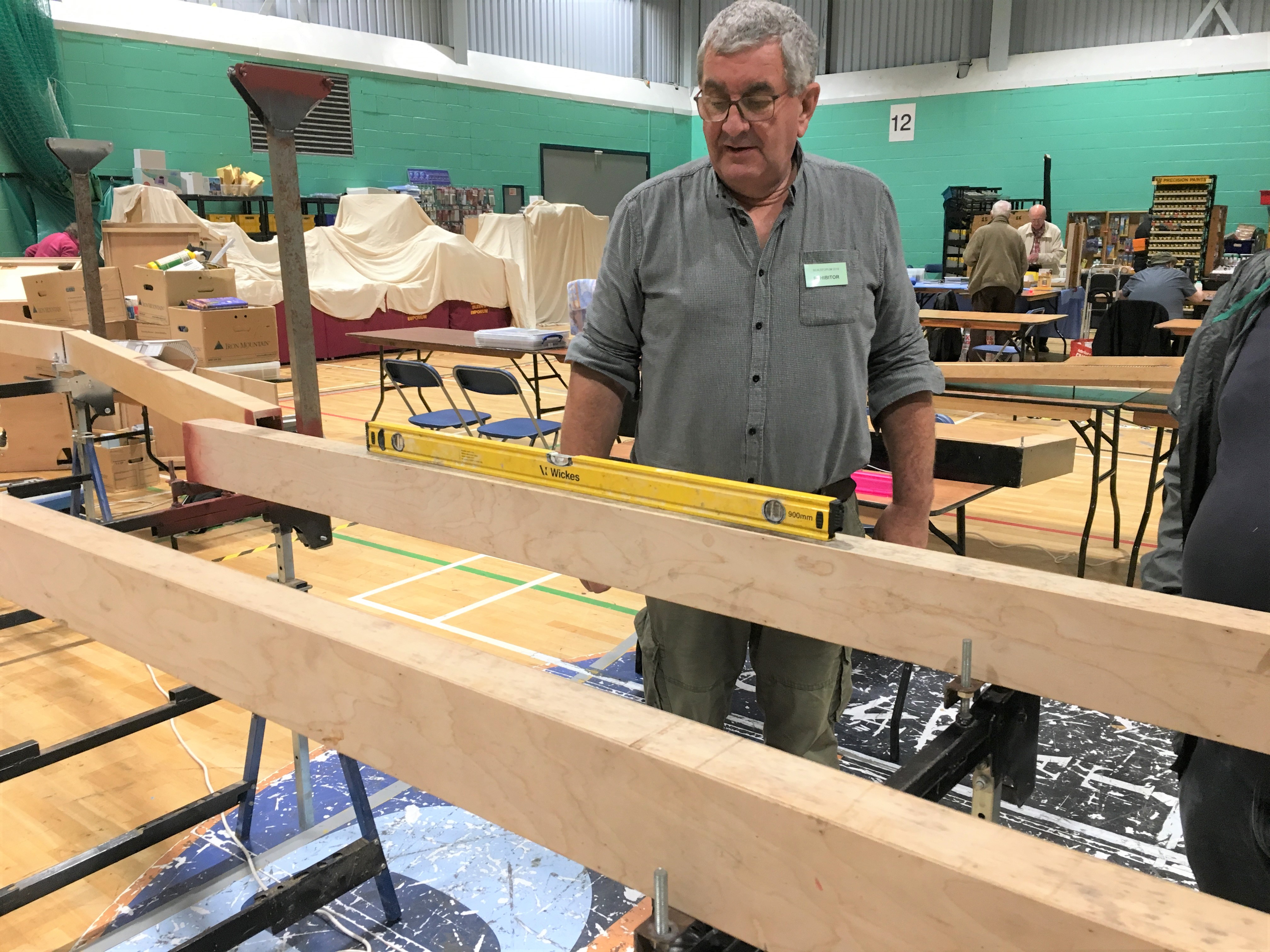
Getting the beams levelled up was speedy even though none of my press team had any experience of my logic! Indeed, with their help, it assembled itself quicker than Portchullin does although the jury is out in my mind as to whether this is simply because it as yet has rather less on it!
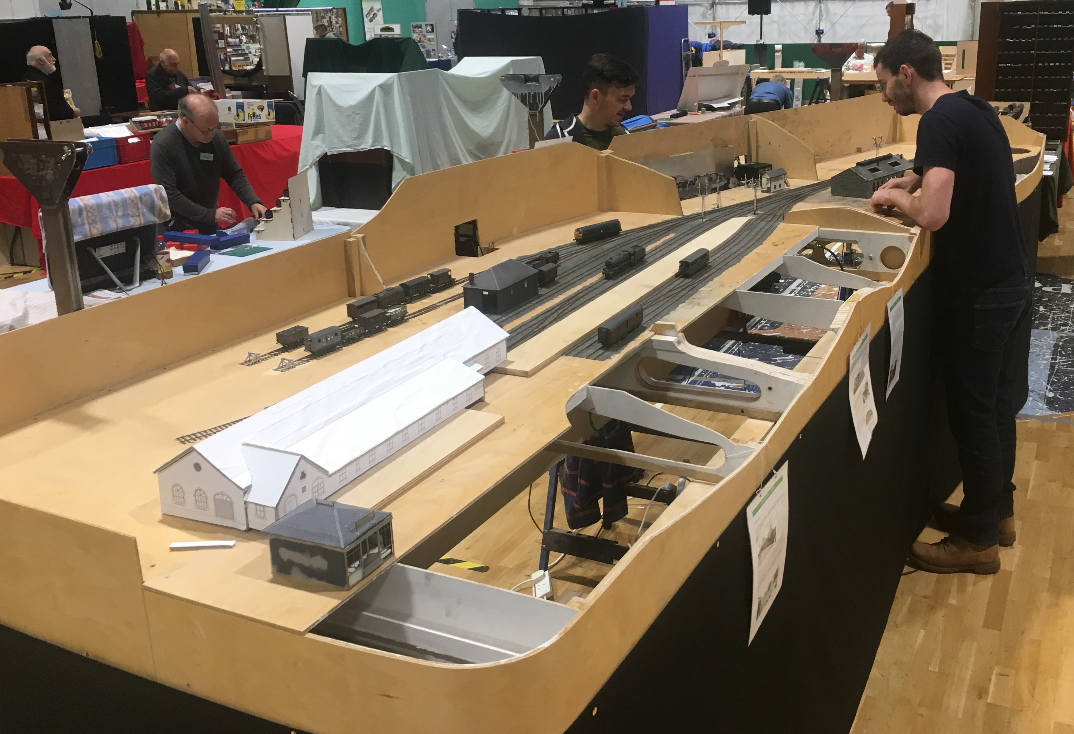
The layout’s size quite quickly became apparent; especially its depth – as can be seen here with Chris in the background for a sense of sale! Please don’t tell my wife this is actually quite big, I have been telling her it is pretty normally sized!
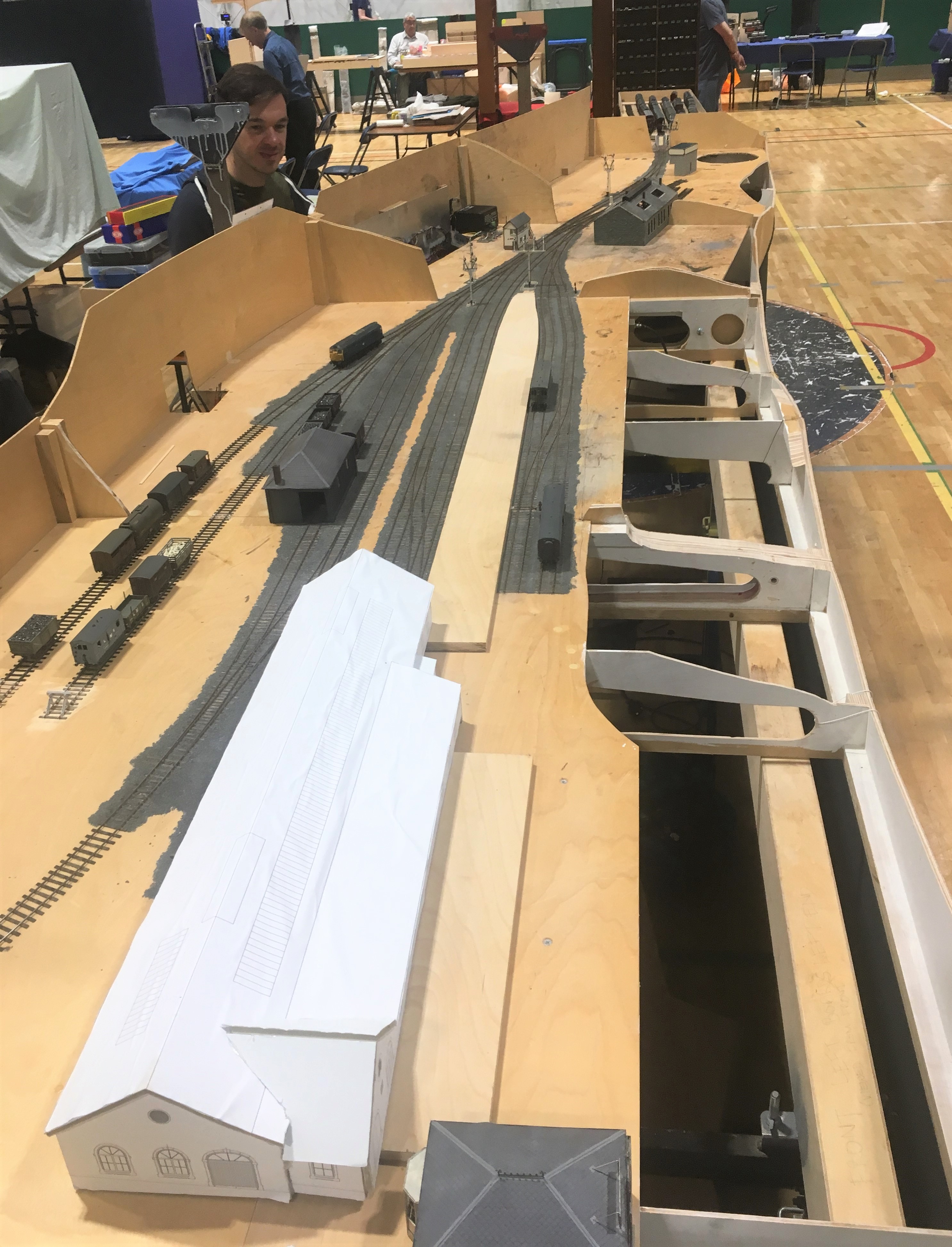
I did not manage to get front side all that often so I have only fairly limited numbers of photographs. Fortunately Samuel Bennett has come to my rescue and has provided a number of photographs to show what it looked like to the visitor.
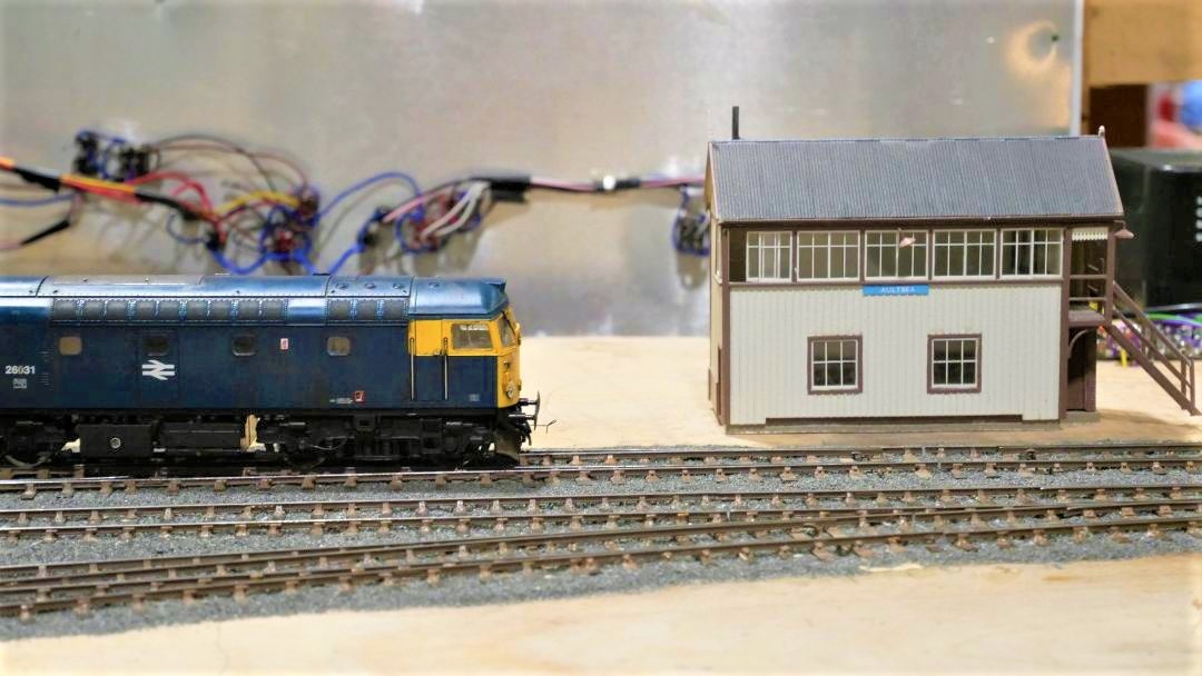
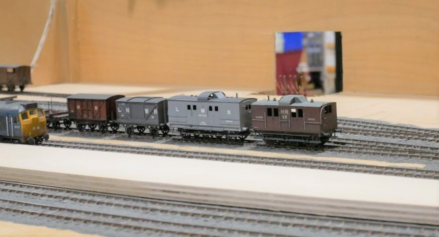
We only had three correct Highland locos chipped up (and one of these decided to sulk after a couple of hours!) so we did break out the blue diesels to make sure we had a fully operational layout. Above there are a few of the locos awaiting chipping on shed and below we have the scene 50 years later!
……..and below is simply confused!
Although the layout did not operate perfectly, it did behave much better than I (and my operating team) had feared! The two page list of faults and issues to resolve with the trackwork, wiring or stock is a fraction of the list that would have existed after Portchullin’s first outing (if I ever had one!).
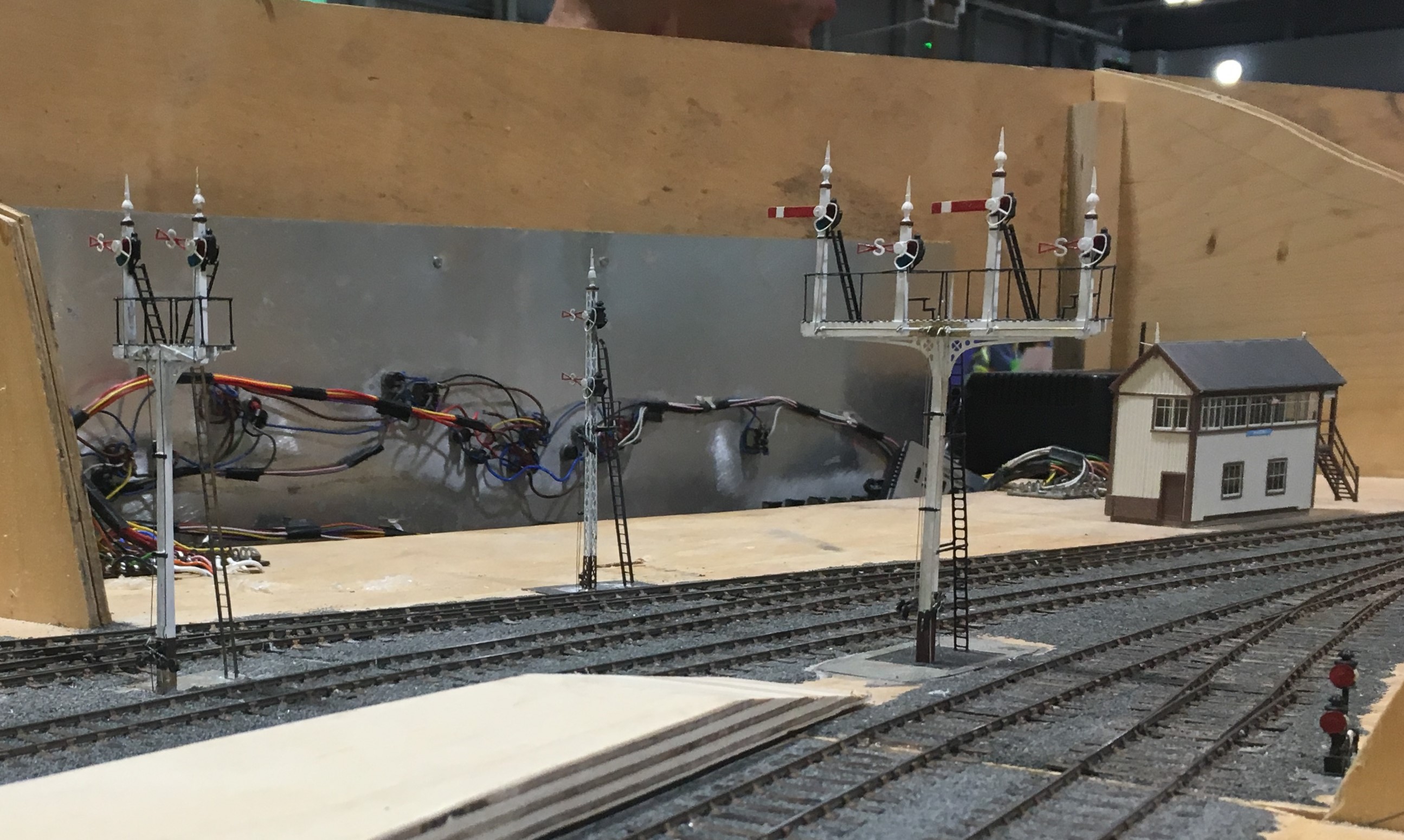
The signals received a lot of comment, even if there was one missing because I managed to damage it as I was packing the layout. There’ll be another post on these soon.

Putting a Backbone into a Shed
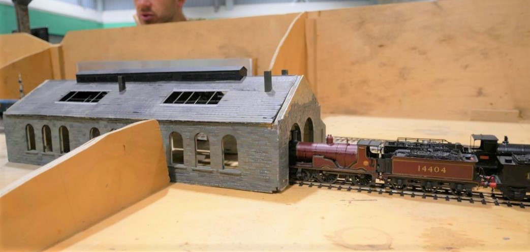
The advantage of a railway company using standard building designs is that you can get to use them more than once. Thus Portchullin’s goods shed will be getting to have a new lease of life on Glenmutchkin.
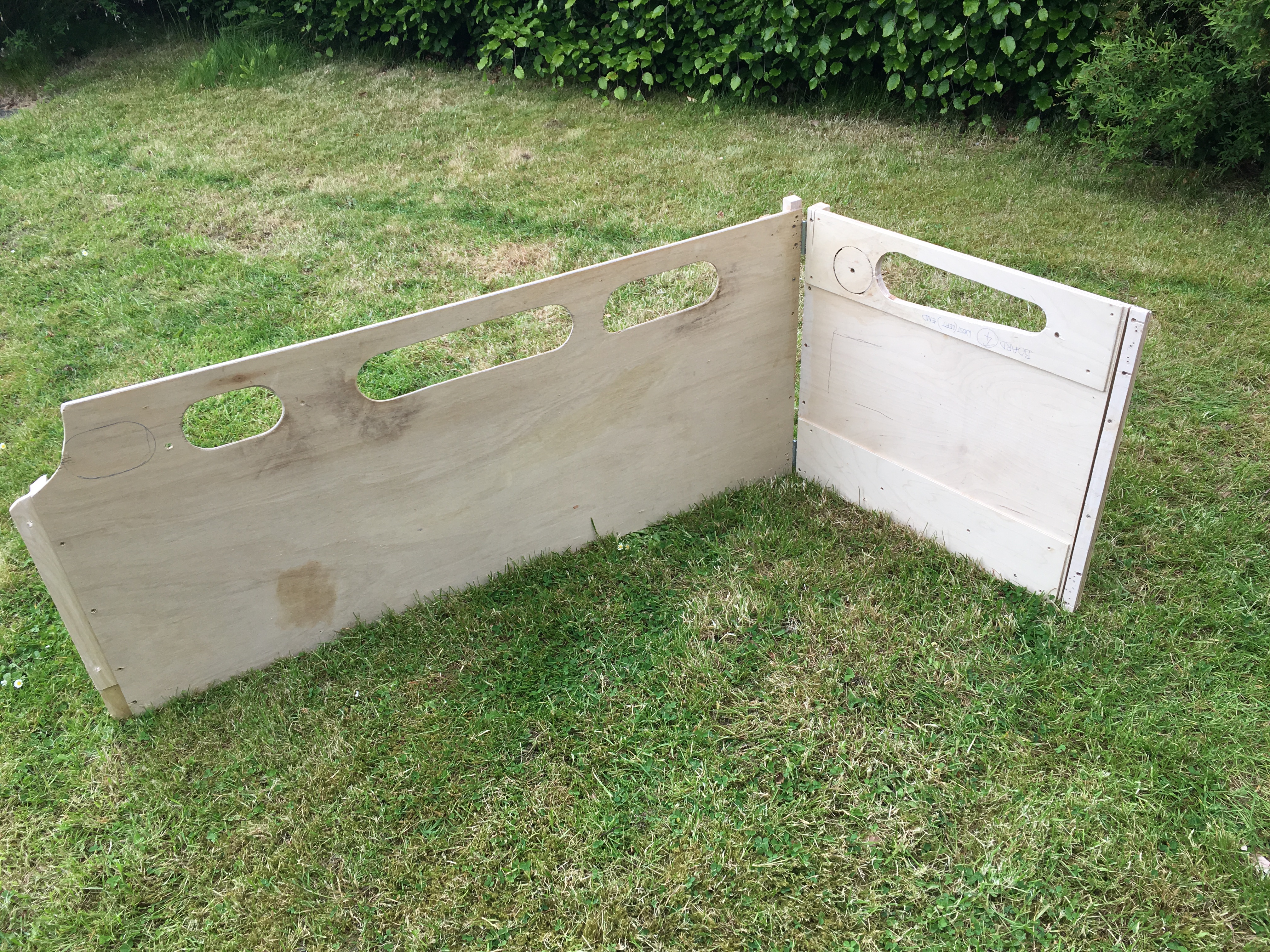
I think my goods shed is the oldest model that I still have and over the years it is fair to say has suffered. Some of this is simply the thirty six shows that it has done with Portchullin (hell………thirty six shows…….!) and almost as many years, as I was about 17 when I made it. However the main issue was the manner in which I built it, with minimal bracing over the top of the entrances. This has lead to it breaking its back and despite several attempts at repair, these have never been long lasting. So it is time to do it properly to allow its reincarnation on Glenmutchkin.
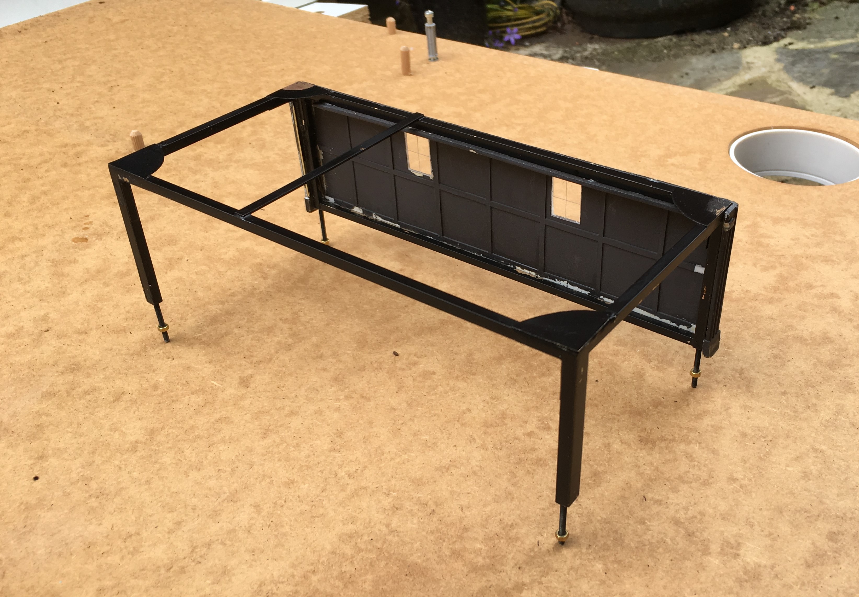
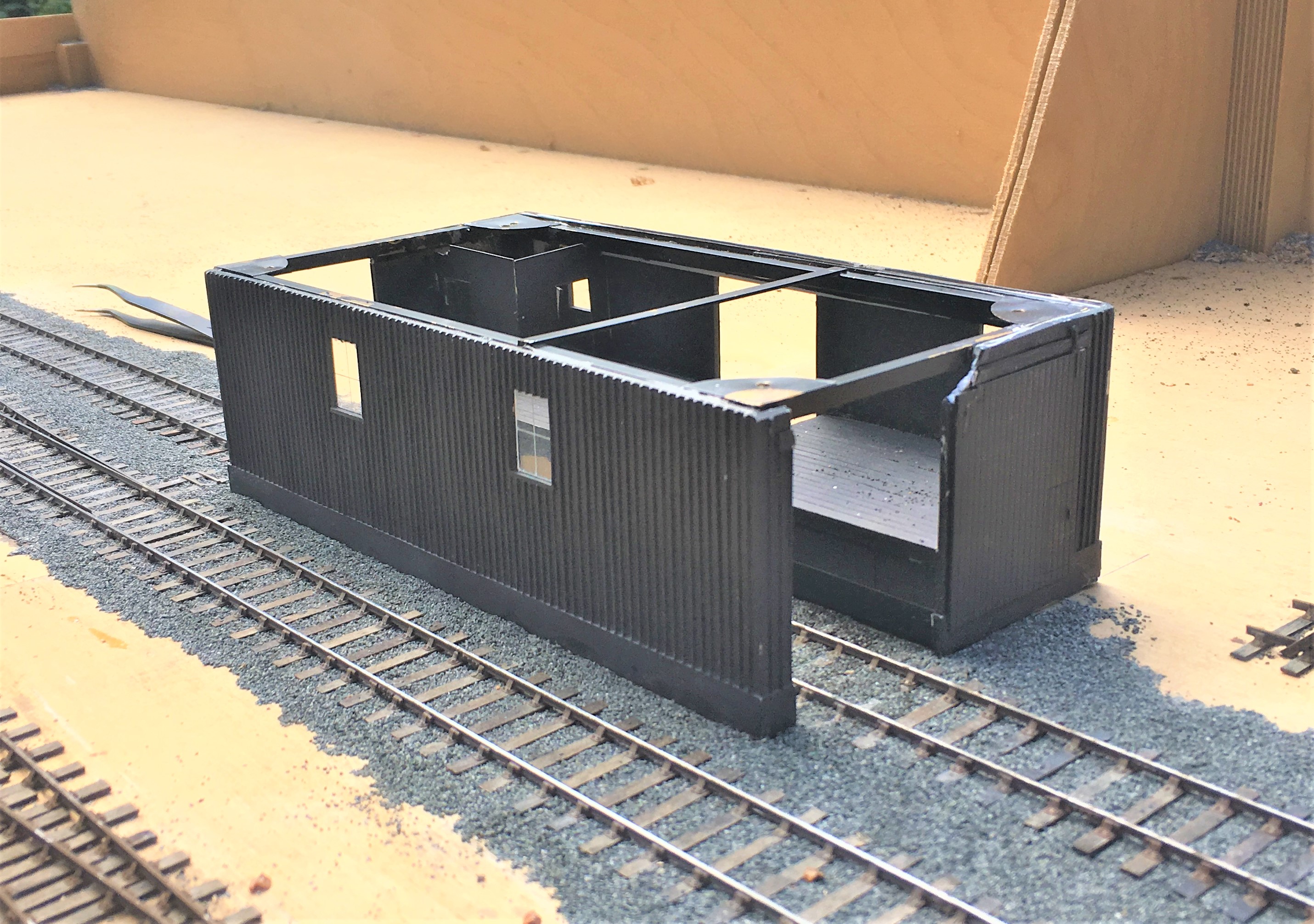
The key to the repair was to introduce a metal skeleton frame inside the model to strengthen it – particularly across the rail doors. This is something I now tend to do at the outset with any largish building I build to contain warping. The frame is invisible from the exterior – the view above shows the frame that I made with the first side attached.
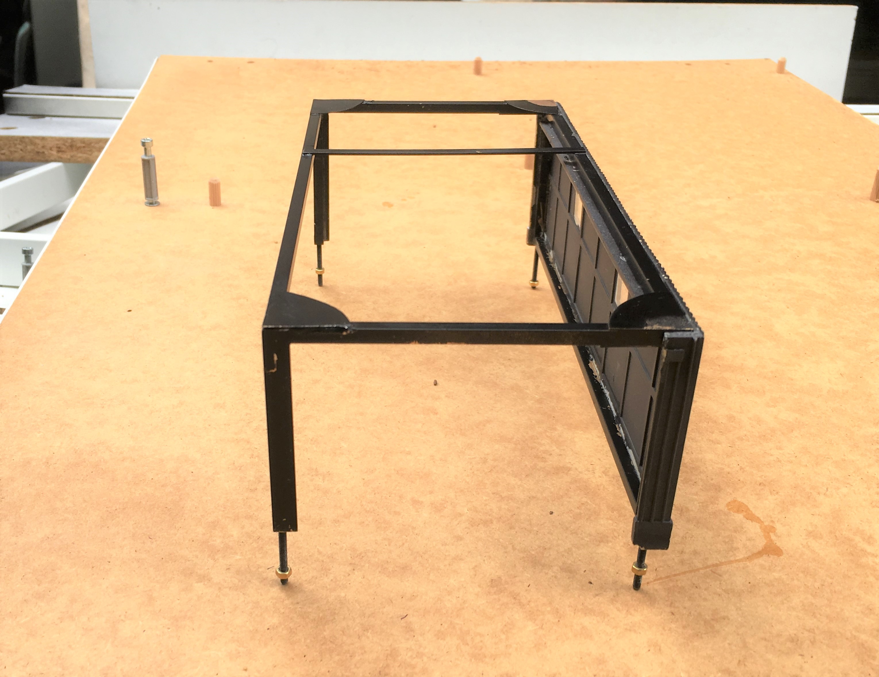
The frame was made with some 3mm square and oblong section brass, with gusset plates – there was a fair amount of metal so it got close to blacksmithing at one stage.
Once the frame was inserted, the model was given an overhaul to repair the other dinks and marks that it has acquired over the years. There were a fair few, as can be seen.
I also to the opportunity to install gutters and downpipes; something I had been meaning to do since I was 17………a bit of a shameful shortfall, given I am a chartered building surveyor!
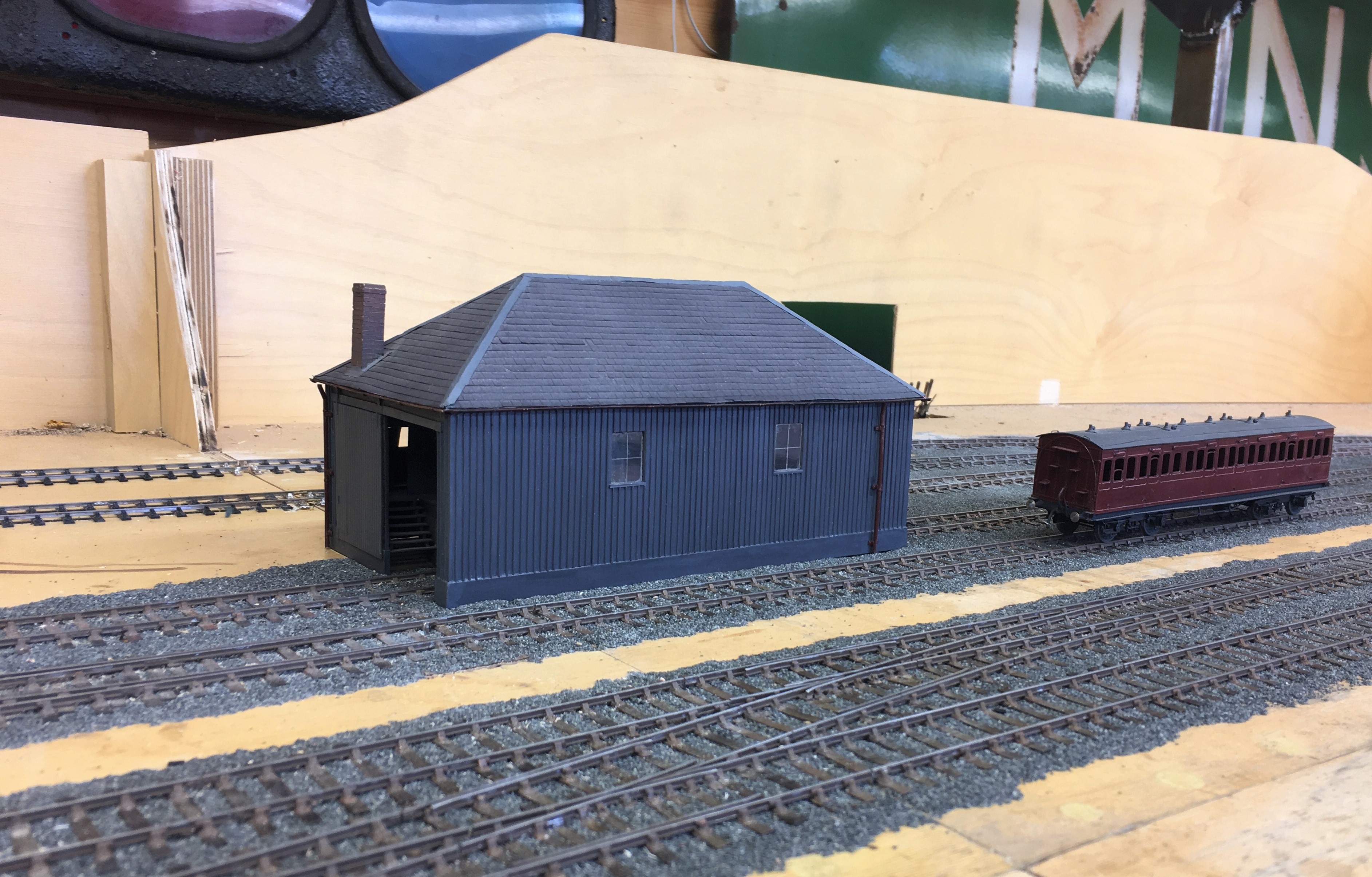
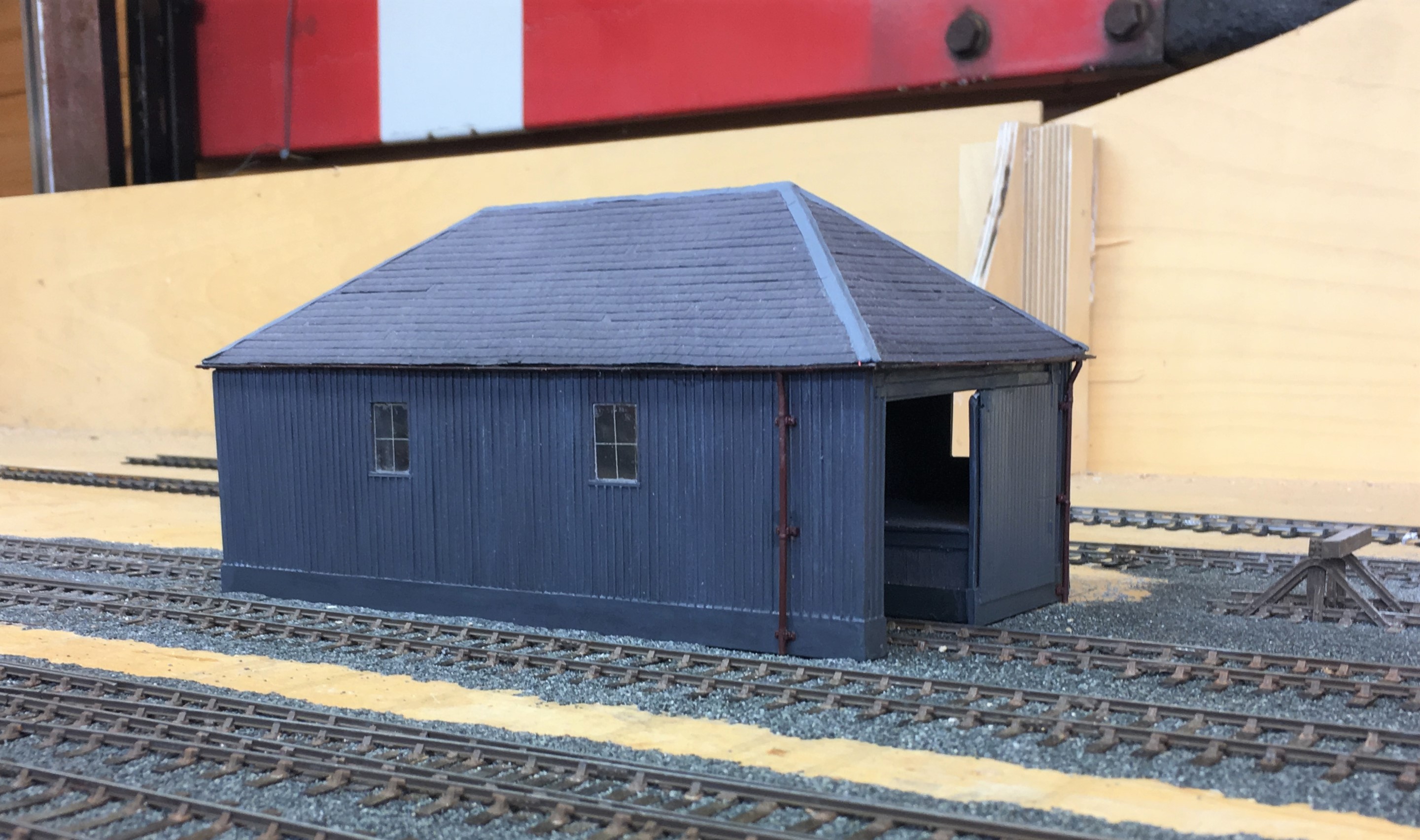
I am pleased with the results and the model is now much more robust so it should do at least another 36 shows! Whether its owner can will be kept under review!
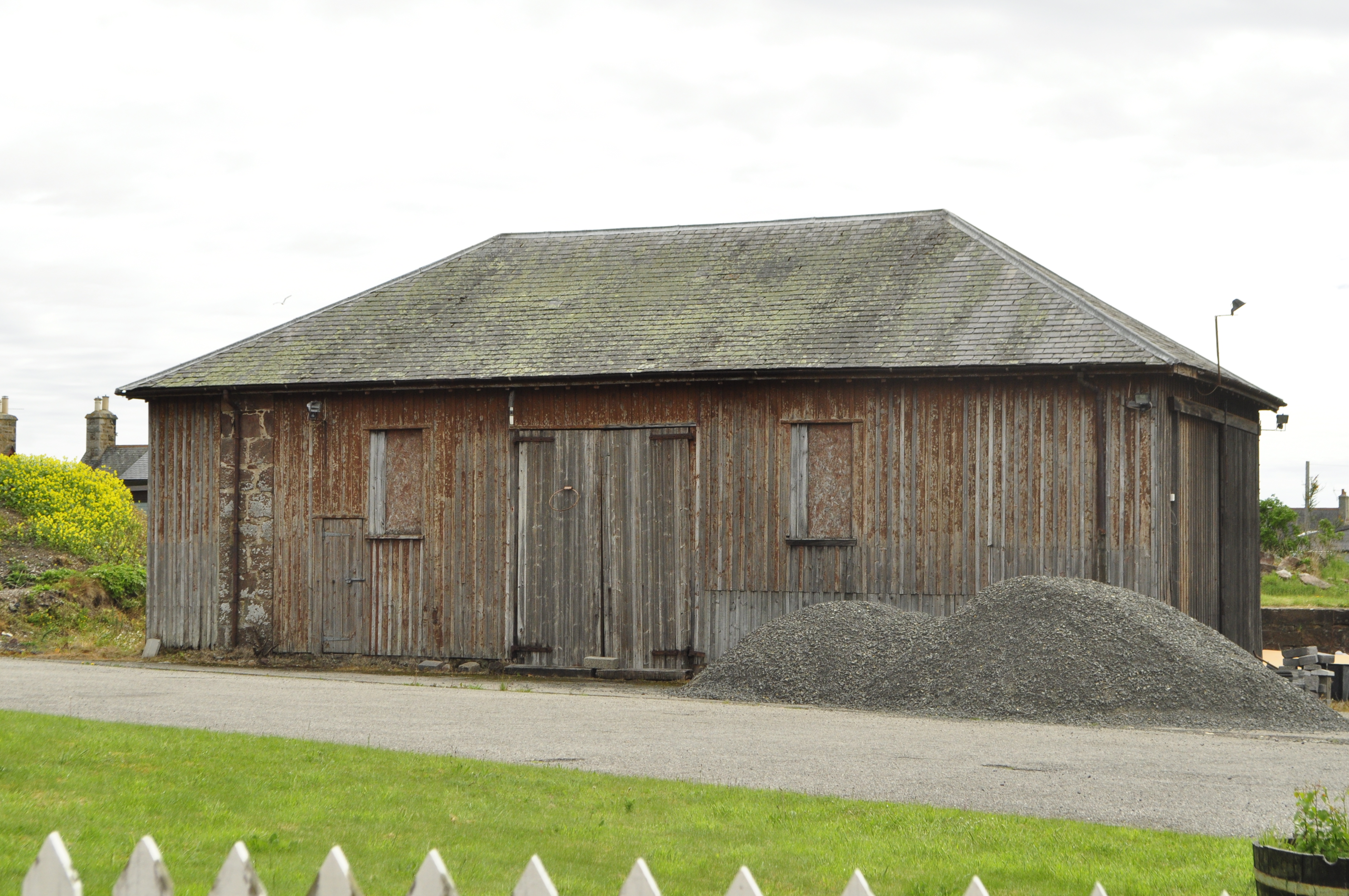
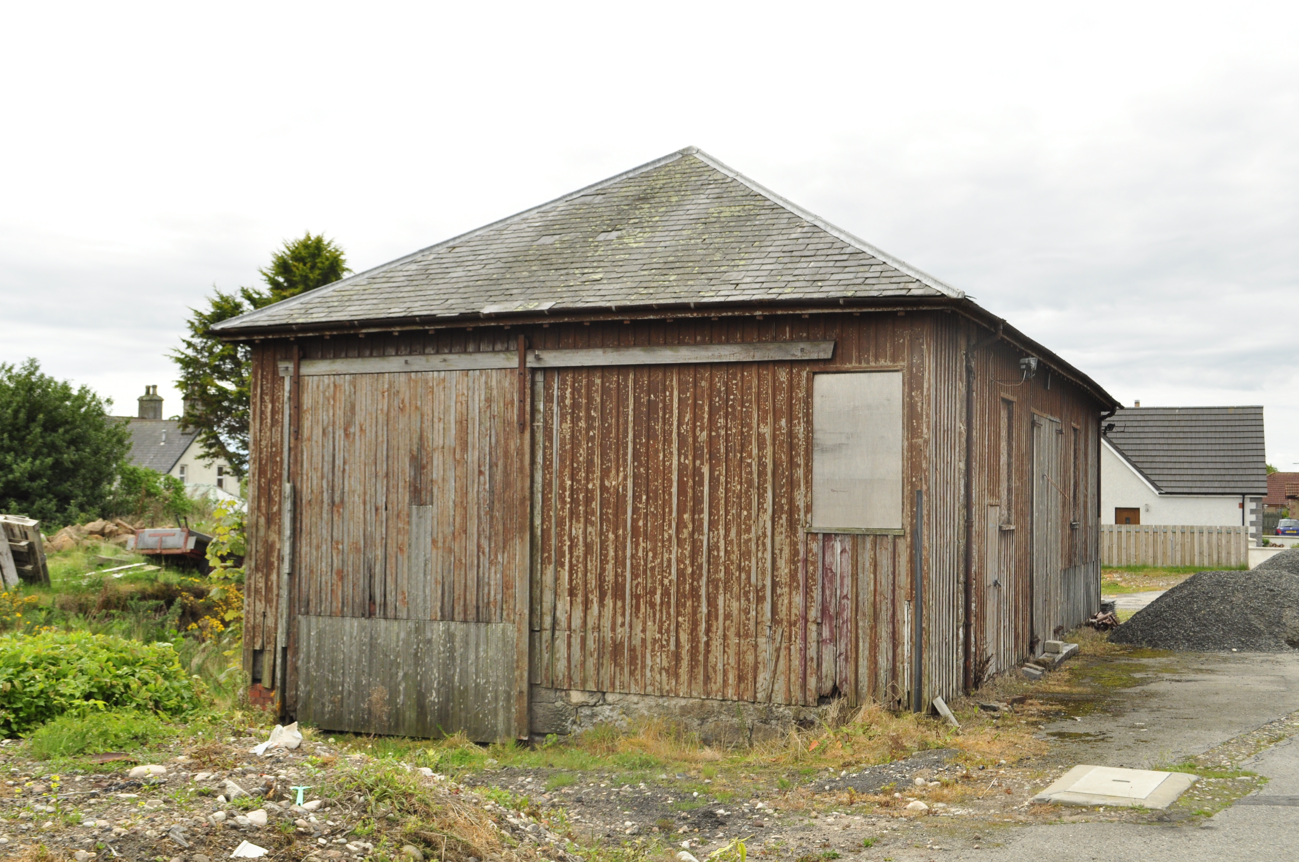
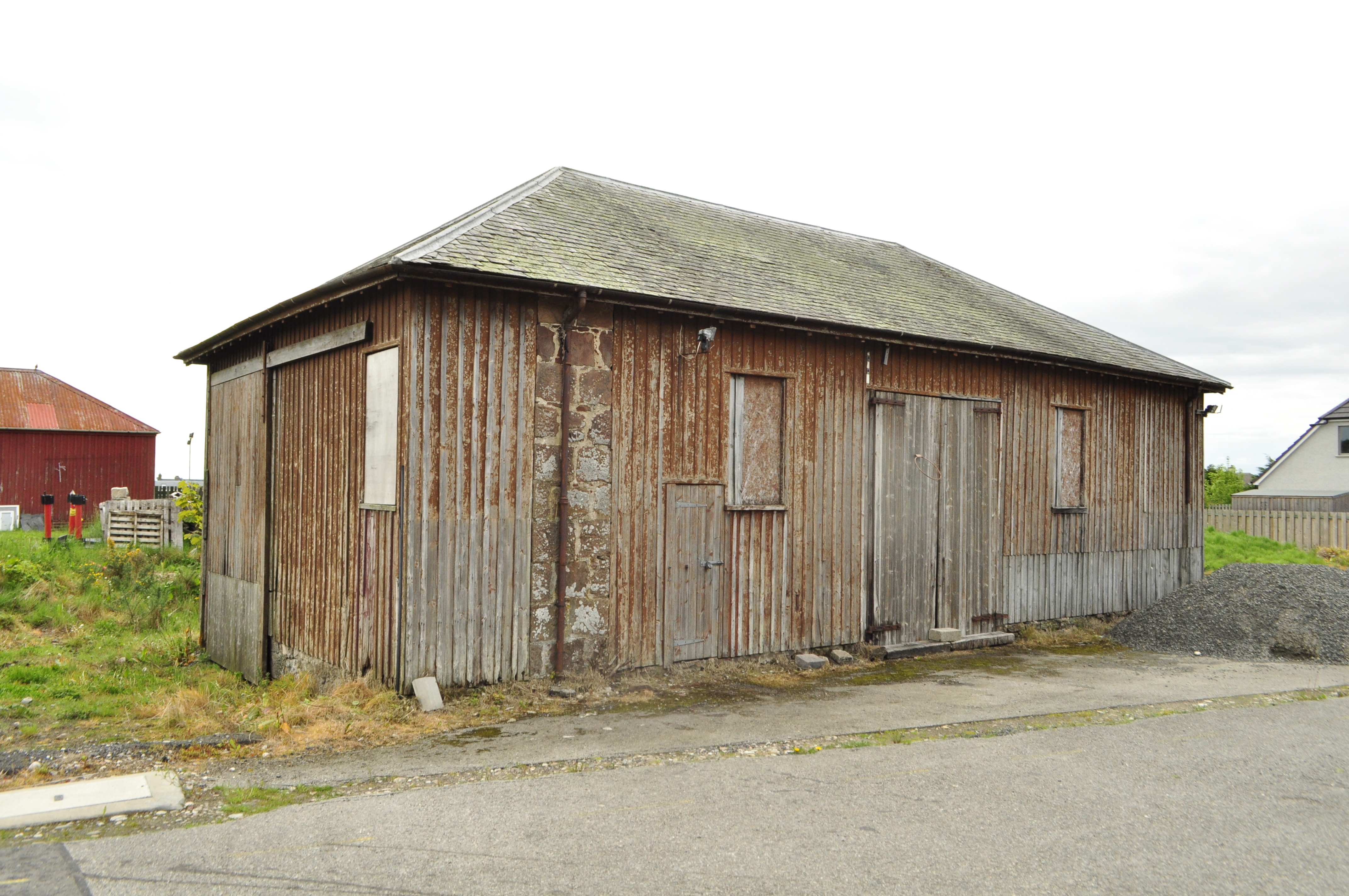
My goods shed is based on the Orbach drawings of the shed at Garve (the August 1952 edition of the Model Railway News). The prototype was swept away in the 1970s and whilst there are a pair of the smaller sheds still remaining (notably at Brora), there are no longer any of the standard Highland Goods sheds left. The last to go was in Golspie about two years ago and I did manage to both photograph and measure it before it went. Here are some views of it before it was demolished:
It Lives Igor; the Monster, It Lives……
Well, it is twitching quite a lot anyway……………..
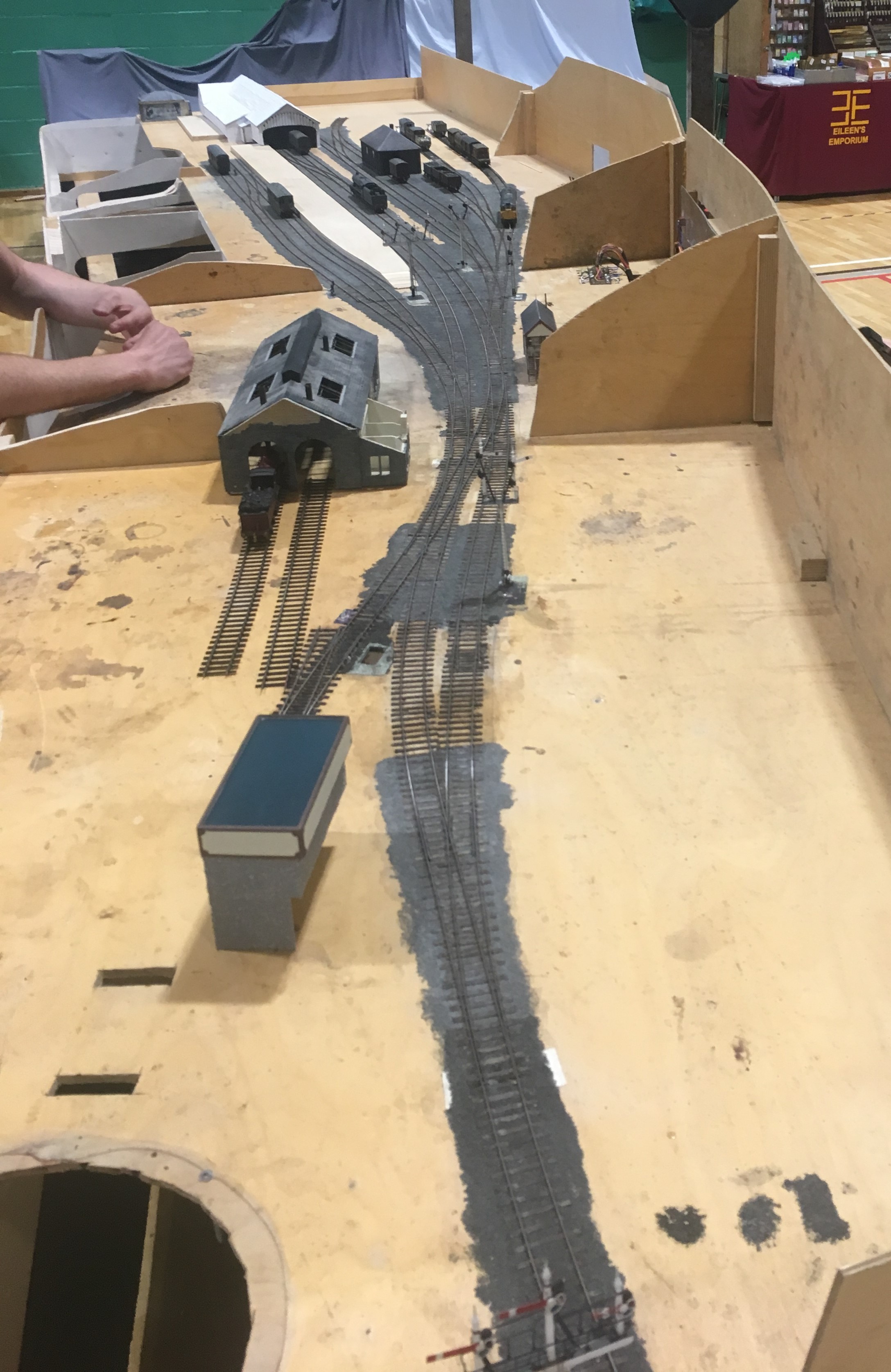
A significant day in the life of Glenmutchkin over this weekend, as I have got a significant proportion of the trackwork which has been laid operational. Admittedly I have an electrical issue in the branch bay (something is wired backwards!), the fiddle yard has not yet been linked to the layout and the single slip still has not be corrected but it works…………..
This is my Loghgorm Bogie (Clyde Bogie series) built by John James. The body is not quite sitting right on it, which is why there is a bit of bouncing; which is a bit worse when it runs faster as below.
Lots to do, but we are getting there! There will be a working layout for Scaleforum!

Boxing Clever
One of the worst parts of Portchullin is the lack of thought I gave to transporting the layout about. One of its attractions is the curve which makes it unusual but this makes the boards big, cumbersome and above all awkwardly shaped to transport. It also made them difficult to create packing solutions for and the limited solutions that I adopted have never been good enough which has plagued the layout throughout its life.
It was a mistake I am anxious not to repeat with Glenmutchkin and now that it is beginning to accumulate some finished elements, it is definitely time to deal with this and create some cases to enclose the boards when they are either stored or transported. My requirements for these were that they provide rugged protection to allow the layout to be transported without risk of being damaged. I also wanted them to be easier to move, in particular on my own, and to pack away themselves without taking up significant amounts of space.
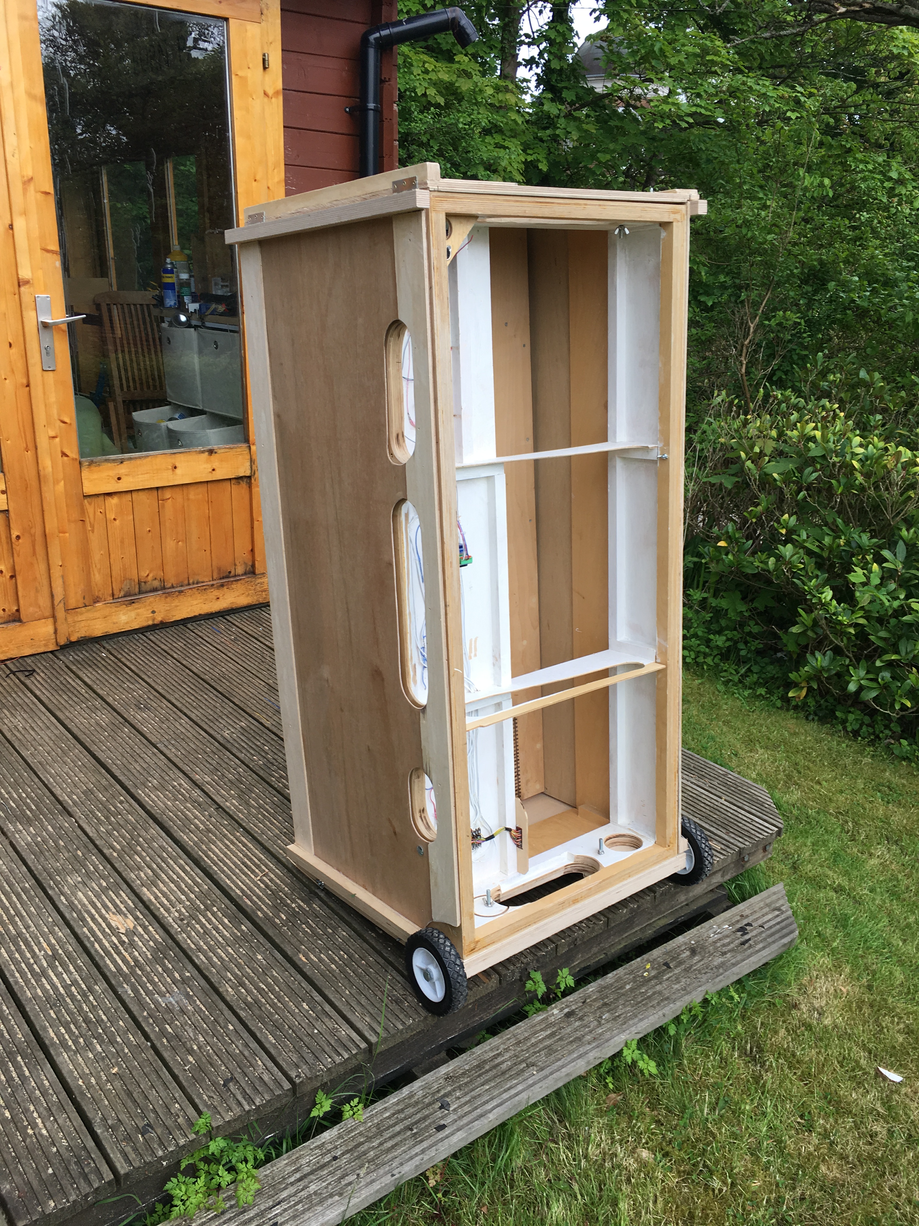
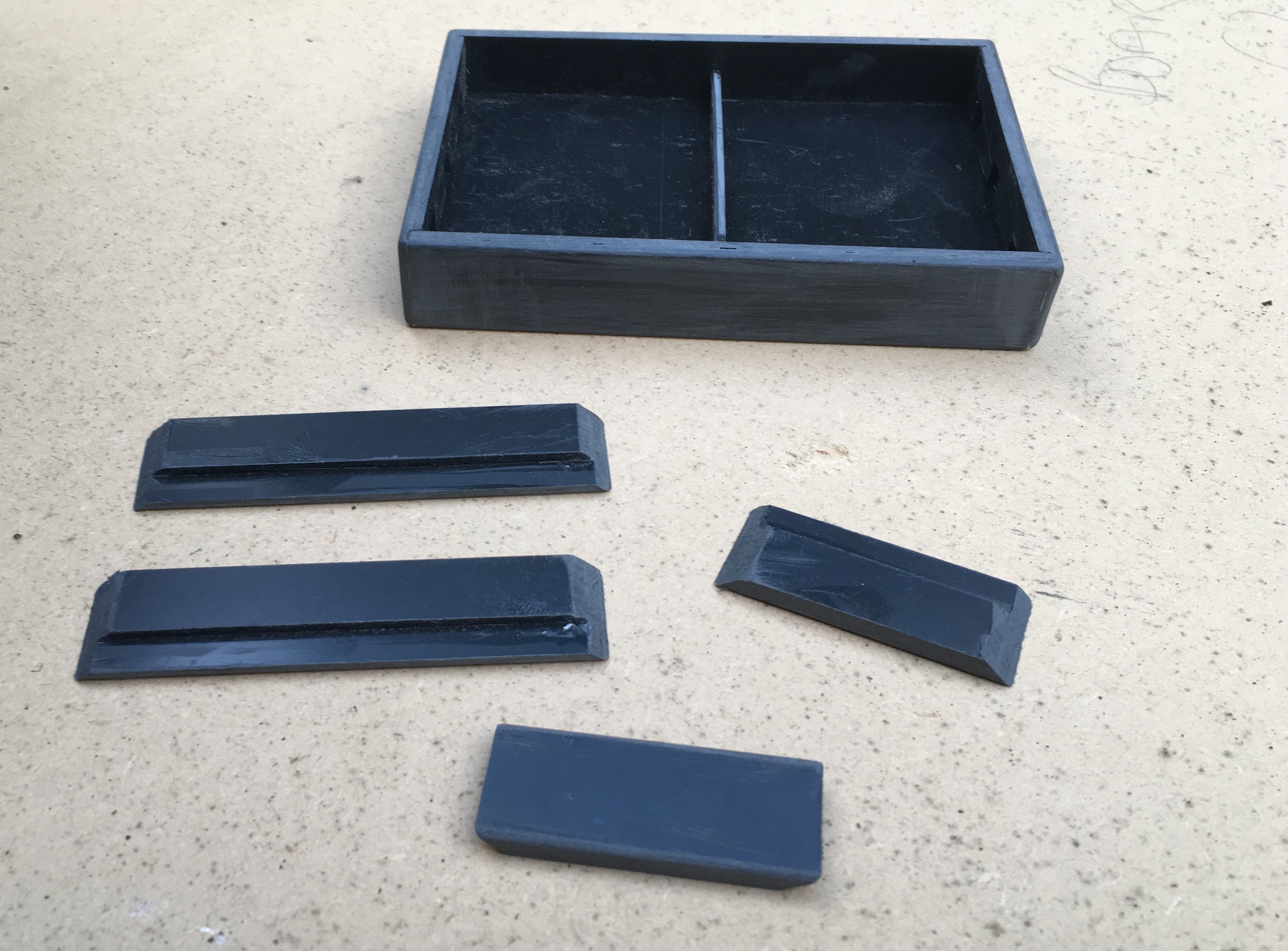
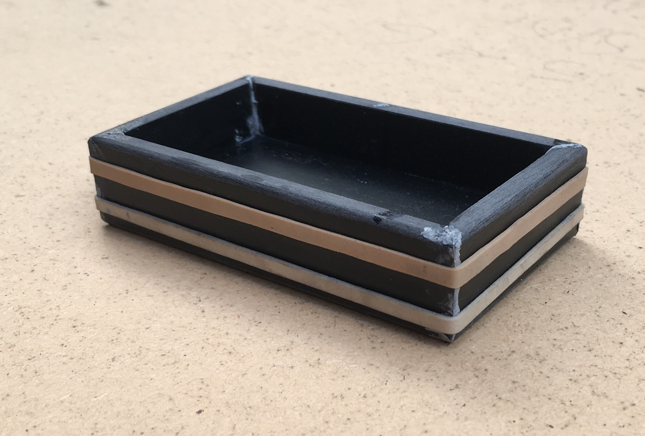
There are (presently, there are plans……) six scenic boards and the crate for the first two – for the smallest boards – is now complete. The concept I came up with is to use end pieces that secure the two boards on top of each other, face to face. To this, I have added larger panels to close in the sides and prevent these exposed parts from damage. To try and speed up assembly and also reduce the space that they need, each end is hinged to and end piece but conceived such that they fold onto each other so that they pack into the minimum possible space.
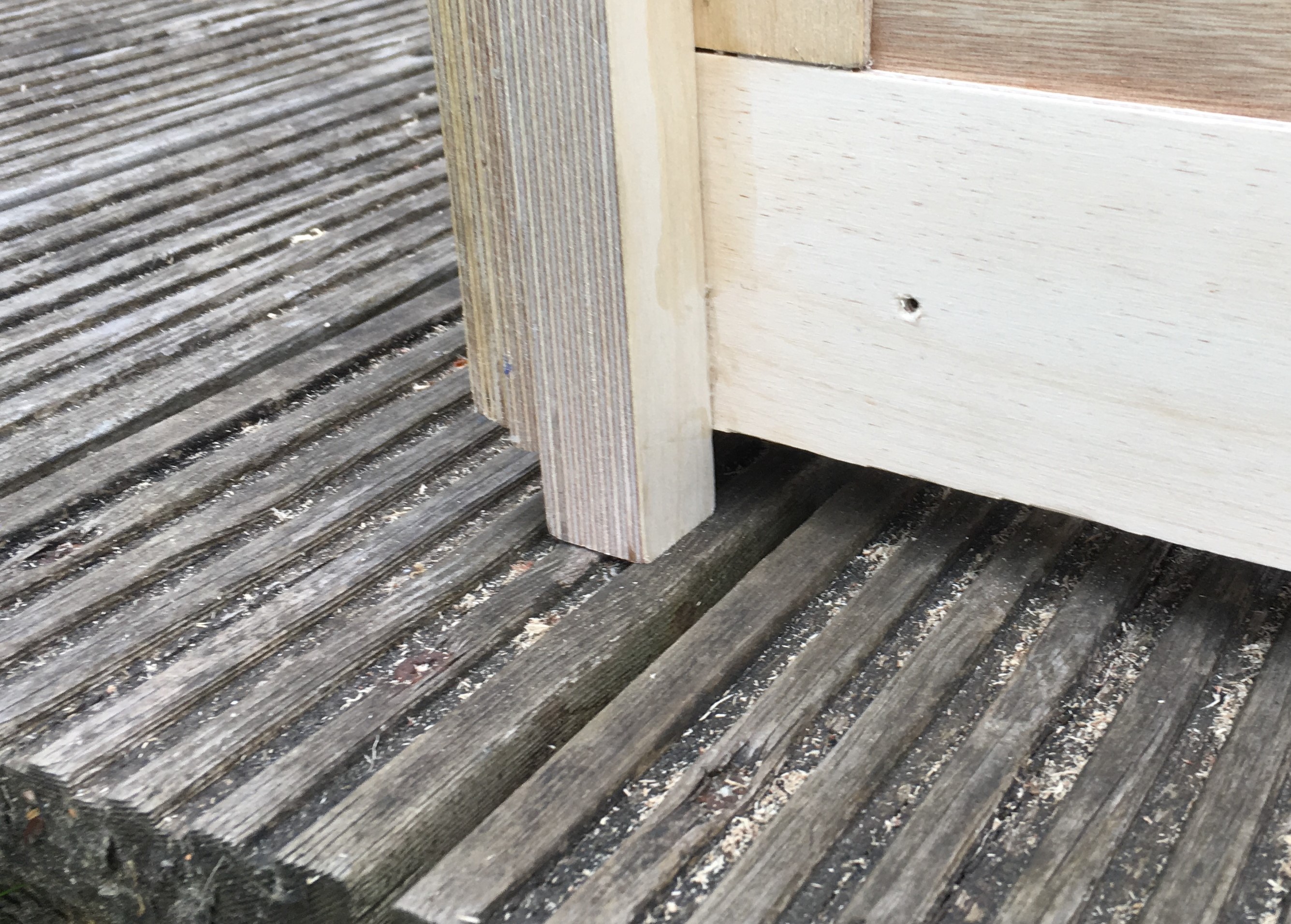
One of the other features I included was nicked from the St Merryn team was to introduce packing pieces to make sure that the ends stand clear of the rail ends. A simple feature that I had not seen described before.
To make the combined case and boards easier to transport I have introduced some trolley wheels – the operating crew are pretty excited with this and can hardly believe how much they are going to be spoilt! The other little trick I am please to have employed is to introduce slight feet to enable fingers to get below the box to lift it.
I have concluded that only the two smallest boards can be paired up in this manner as they are already quite heavy and will get more so as I add the remainder of the features to their topsides. Thus the remaining board cases will be slightly different.
The Glenmutchkin Pharmacy – Part 2; Beware Roofers!
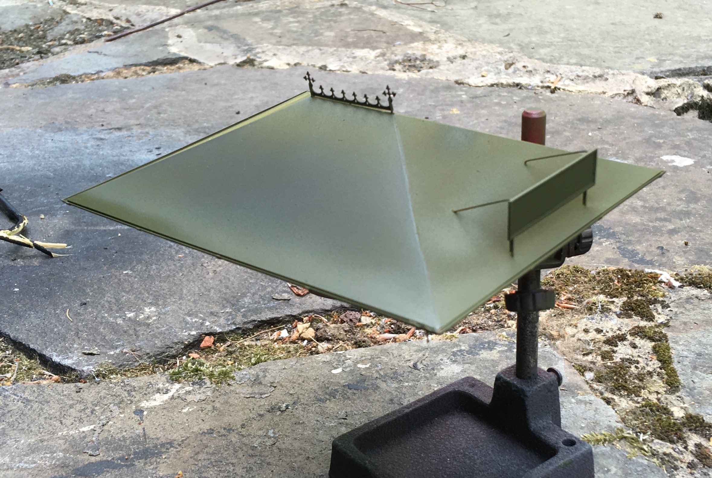
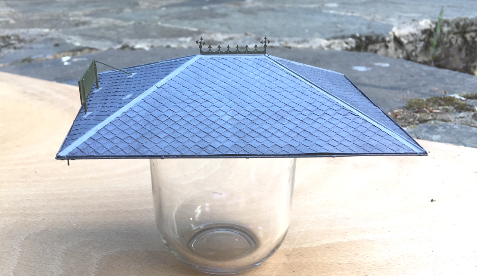
Progress with the Pharmacy building has continued and the roof is now nearing completion. I preferred using sheet metal (in this case nickle silver) for roofs as I find it is the easiest was to then include gutters. In this case, I designed the roof as a simple fold up etch and subsequently the gutters were formed by half round section from Eileen’s Emporium.
One of the pieces of artistic licence I went for relative to the real Kyle Pharmacy was to elongate the building slightly. This was partly because the prototype was a bit square and squat but also because I fancied including a decorative ridge piece. The Victorians and Edwardians did love a bit of decoration and this included the details to their buildings. There were numerous contemporary catalogues of architectural bits and pieces from which to choose from and I liked the idea of something pretty – especially given that this model will be right at the front of the layout. So I created a design of my own and etched it; along also with the characteristic sign that is so prominent in the photo in my last post.
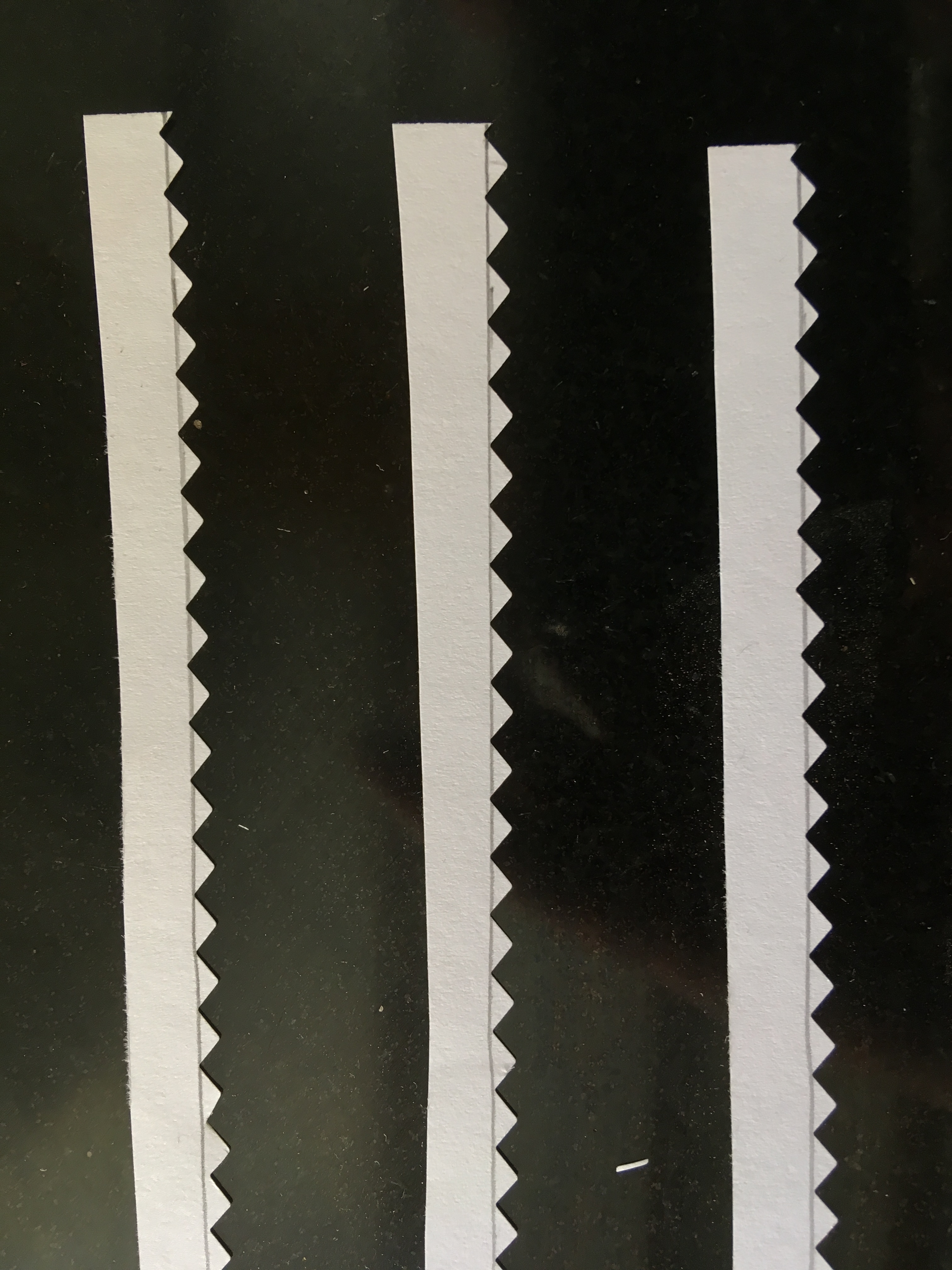
Those that looked carefully at the prototype photograph in the last post will have noted that the roof slates were diamond shaped. These were, in fact, asbestos slates and were quite a common material for pre-fabricated and simple buildings such as the Kyle Pharmacy. Clearly they needed to be modelled but I did no fancy my chances of cutting the odd couple of thousand slates consistently. I toyed with getting some laser cut or cut on a silhouette machine but then had a brainwave – pinking shears.
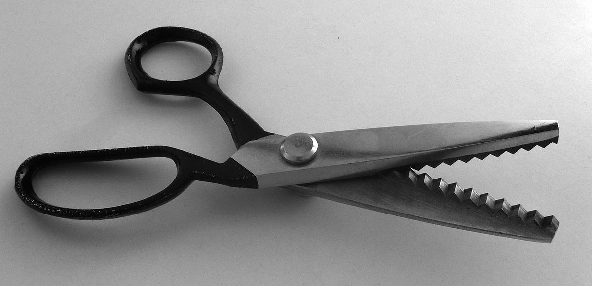
For reasons I don’t quite know, dressmakers use these to create zigzag cuts and even better, my wife had a set. However, she spotted me taking a look at them which meant I had a very firm talking too and was immediately banned from using them!! Researching them on the internet showed that they come in a variety of pitches but be warned not all of them have 90º serrations. I did find a set with a 4mm pitch which was a bit less than the 5mm that I thought was scale for the Kyle Pharmacy but as this equates to a 12 inch slate, I thought it was plausible and not a bodge too far. As you can see below, they produce a neat and consistent serration.
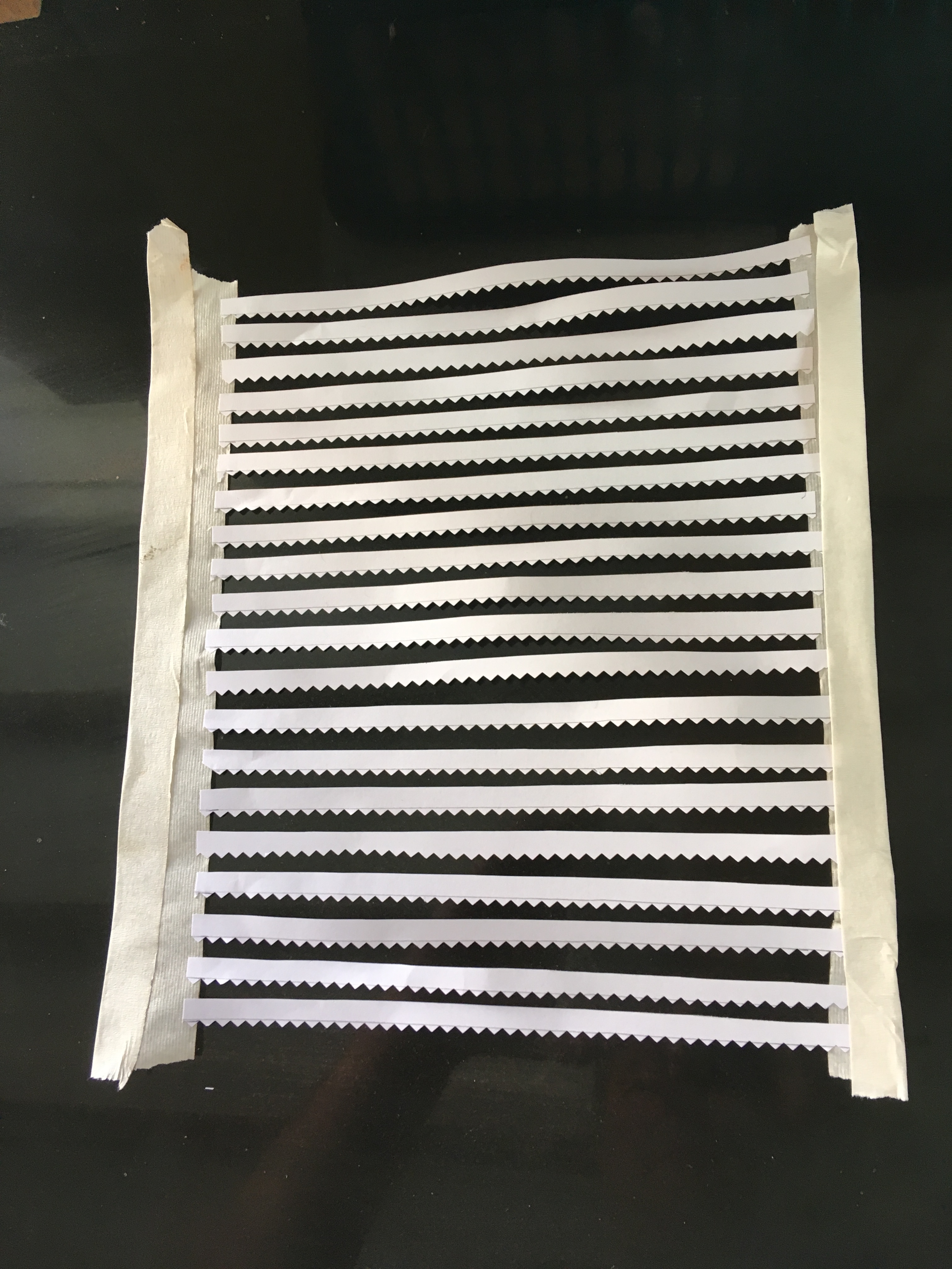
I cut the slates from plain paper in strips which I then sprayed a mid-grey colour because I felt that asbestos tiles might be a bit lighter than normal welsh slates. I deliberately allowed a tiny bit of inconsistency of colour to creep in, to provide a little texture to the roof. However, painting them was not easy as the air of the airbrush sent them flying – so I had to create a cradle to mount them in for spraying.
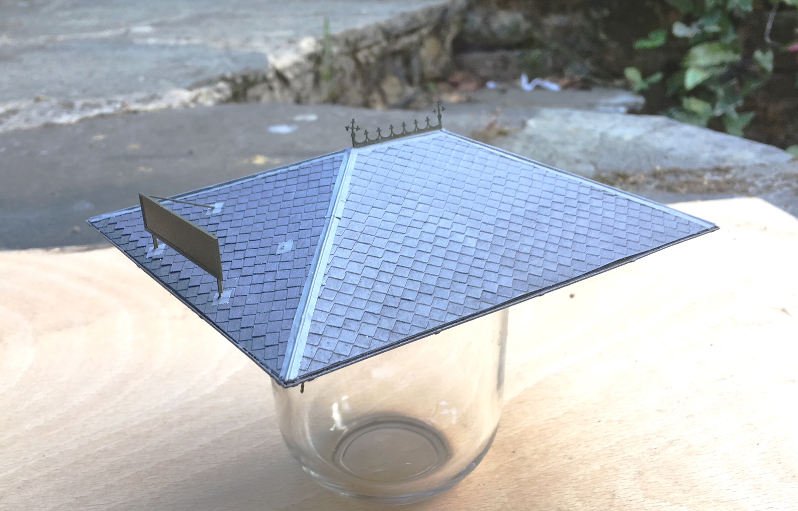
Once painted, I secured them with spraymount and carefully set them out, with the point of the diamond to the row above meeting the apex of the one below.
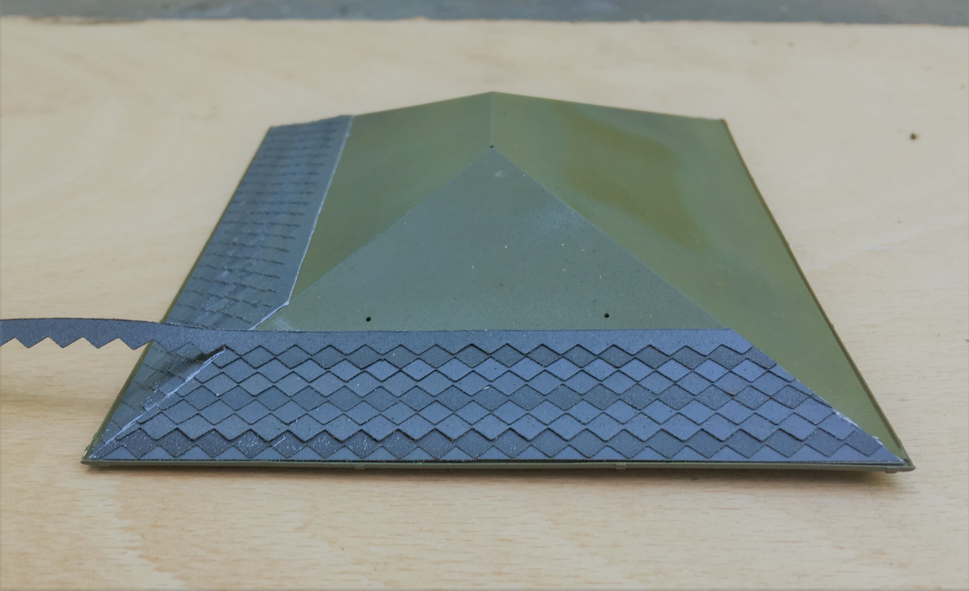
It takes some time (around 2 hours for a fairly small roof!) but I think the effect is quite convincing. I find the the best effect to make it look natural is to lay the slates as consistently as possible – you don’t achieve perfect consistency and these small imperfections end up making it that little bit more. Deliberately introducing inconsistencies tends to look a little contrived; including in this case my slightly differing shades, however, this was expected and can be overcome.
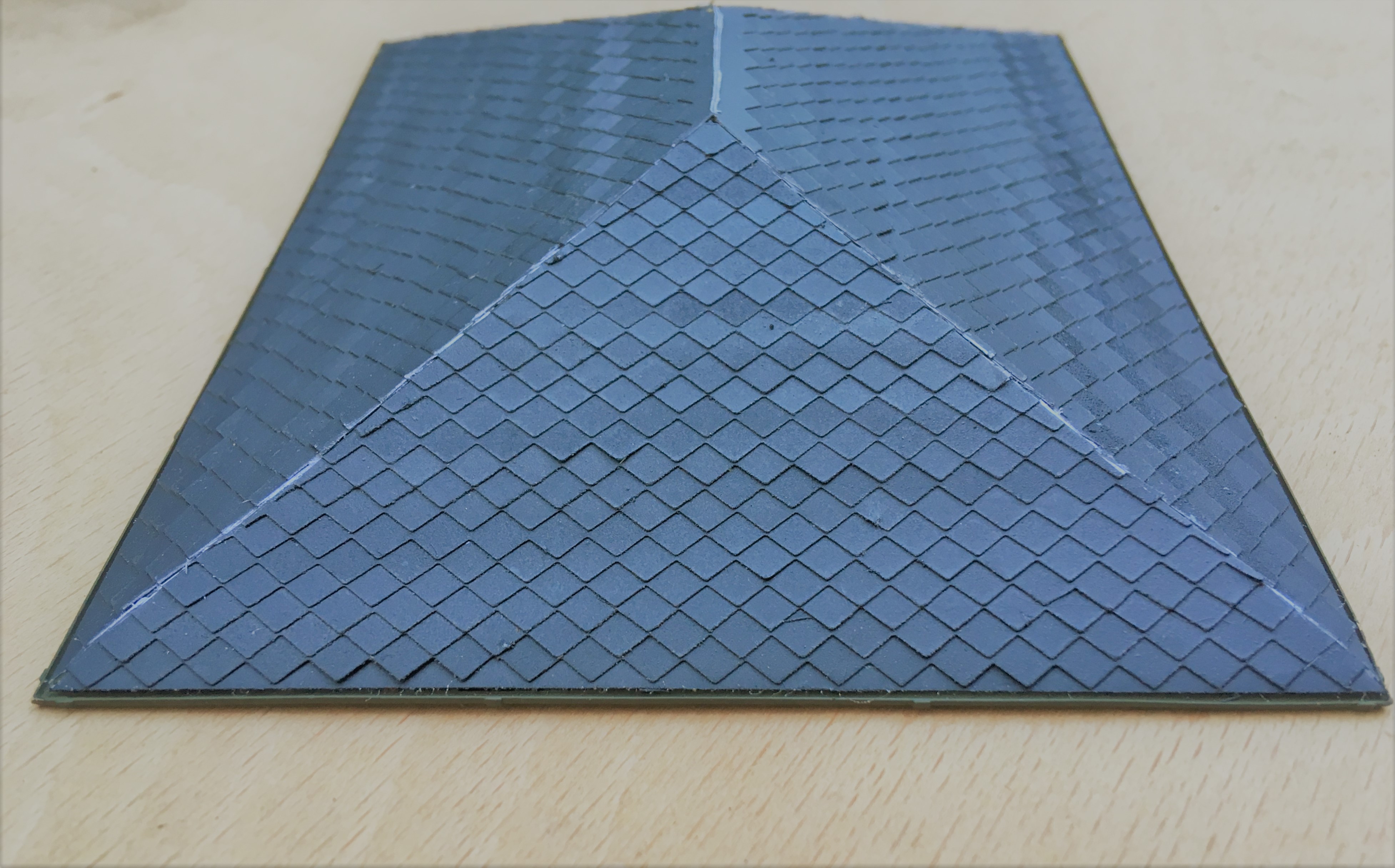
The blend the colours together, I washed the slates with artist’s acrylic always ensuring that the brush stroke was down the roof to mimic the flow of the weather.
I also formed the ridge and hip flashings with cigarette paper which I had first sprayed with grey primer and then secured with more spraymount. This was laid over 0.6mm brass rod to give the central lead roll effect – this was secured in place with superglue. I initially tried to make the lead flashings in sections so that the correct laps between one piece and the other was achieved but I never got close to a neat or believable finish. Thus I ended up doing this in one piece per run.
The front signboard will need some more work yet (partly because I have damaged it!), which will feature in a future post as I am going to have a bash at producing transfers.

The Ancient and Noble Order….
Back in one of my very first posts I explained the origins of the layout’s name; which has a lot more to it than might first appear (for any of you that have missed this post, follow the link back to discover the world of Glenmutchkin that Professor Aytoun created.
I had been aware that others had discovered the name and, like me, piggy backed a good story for our own purposes – there is even an entry in “Railscot” for the line. What I had not realised was that this seems to have been going on for more than 100 years!
This changed when I had an email out of the blue from a charity seeking to discover a bit more about the story and had come across this blog. Their email was prompted by a donation they had received of the medal below, which they were trying to find the story behind.
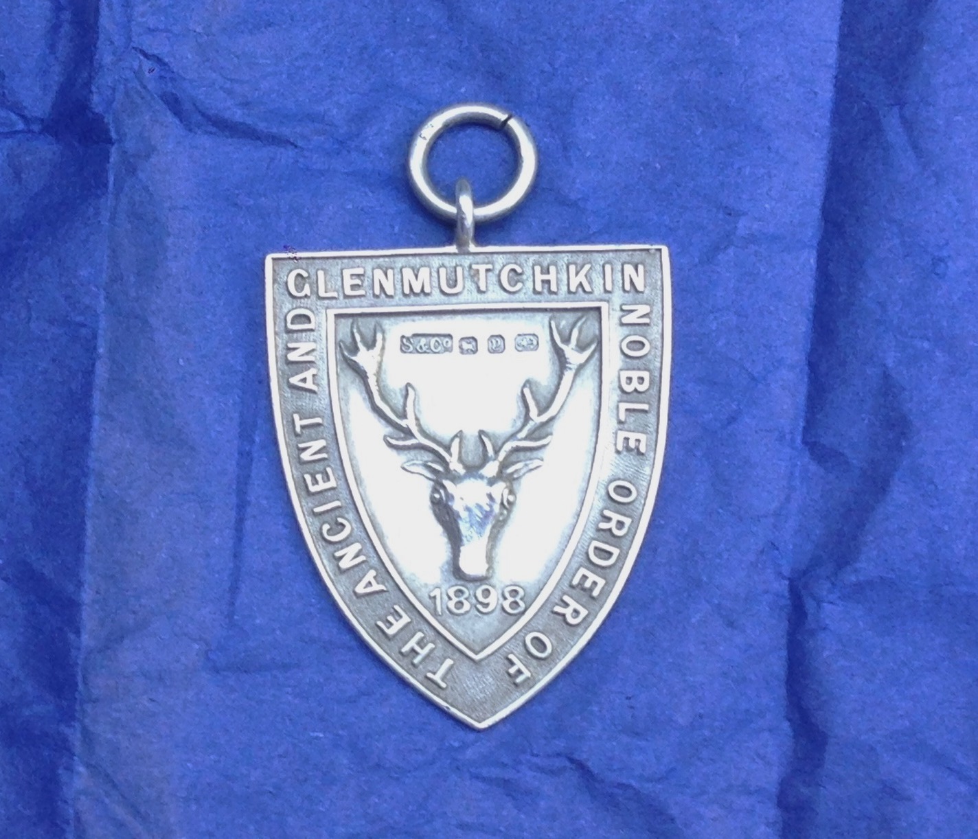
We have been able to find out very little about the medal beyond the hallmarking (Birmingham Assay Office in 1898) and that it was made by Shipton & Co (who are – as you will see if you follow the link – still trading. Our supposition is that, 50 years after the publication of the story, it was still known of and a group – perhaps a university society or similar – used the story to mark some sort of event or other action of one of their members by striking this medal. Given that Professor Aytoun’s story is centred on skullduggery and tall tale telling it is intriging to wonder what it might have marked!
So if anyone does know more about it, do please let me know and I will update the blog if any more information comes to hand.

Nothing to See Here
Well, that’s true of the top side, where nothing visible has happened of late but there is progress when you look underneath.
I have spent more than a few hours soldering dropper wires on about half of the track that has so far been laid. All is neatly colour coded (hopefully).
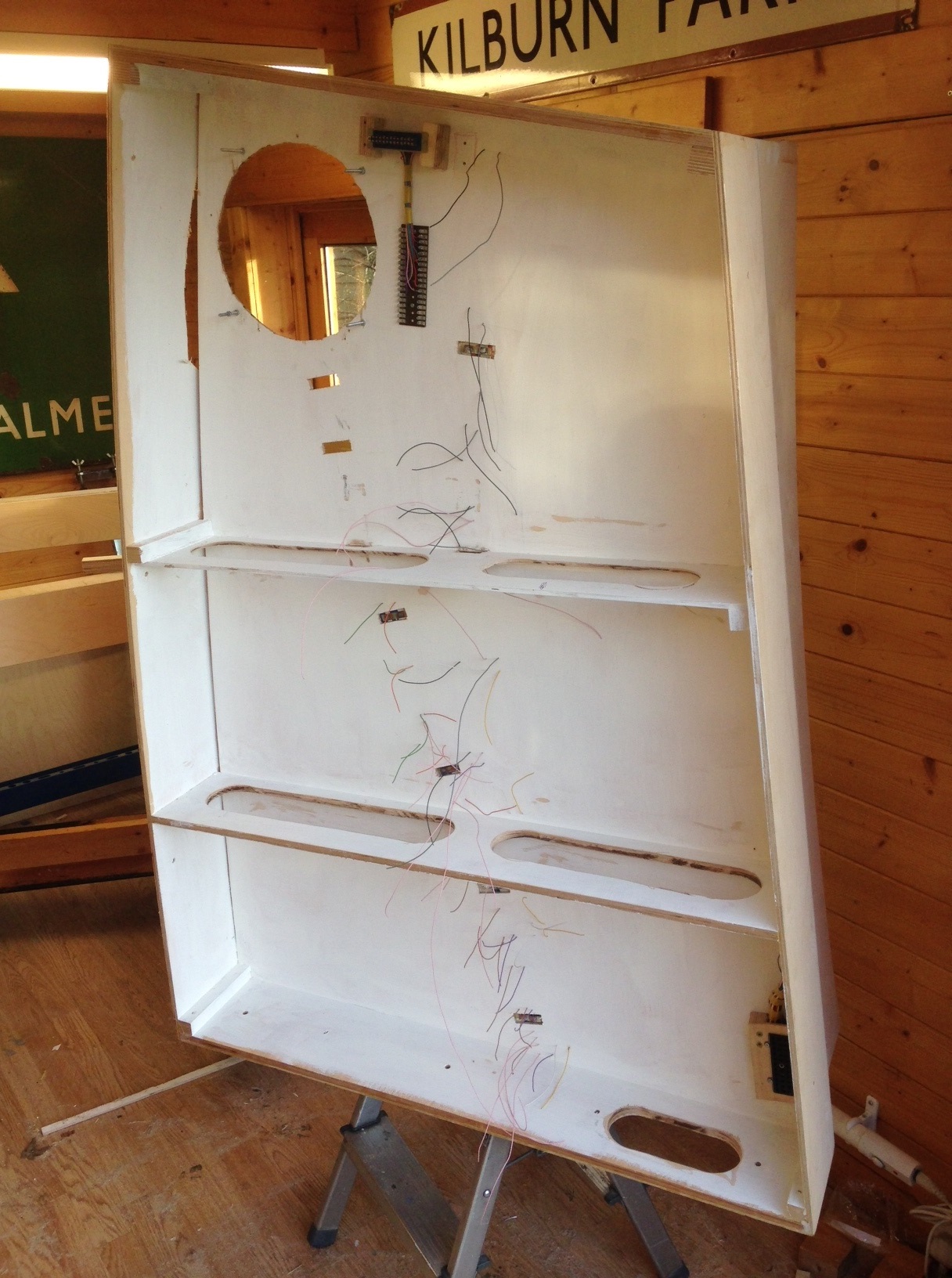
Another development in comparison to Portchullin is the painting of the entirity of the underside of the layout white. This is to make everything clearer and will, hopefully, make it easier to deal with issues with the layout set up – although I am hopeing for less issues!
Even more hours (weekends even!) have been spent making up jumper connections, so hopefully the wiring will speed up in the coming weekends! I have spent this time to work through the logic of the wiring across all boards and there is a full wiring schedule in place – none of the wonky logic on Portchullin this time!

Control Freak
I have been back onto the layout of late, with a view to get the first wheel turning on it before too long. That means attacking the electrickery things, beginning with the control panel.
I made a start on this by drawing up a diagrammatic representation in MS Paint and then using this to get one of the online firms (Vistaprint) to print me up a poster board to form the basis of the control panel. I am not sure I chose the right material as it turned up on a light weight foam board and I had to mount a sheet of aluminium behind for it to be stiff enough to be useable. But it did look pretty smart I thought………….
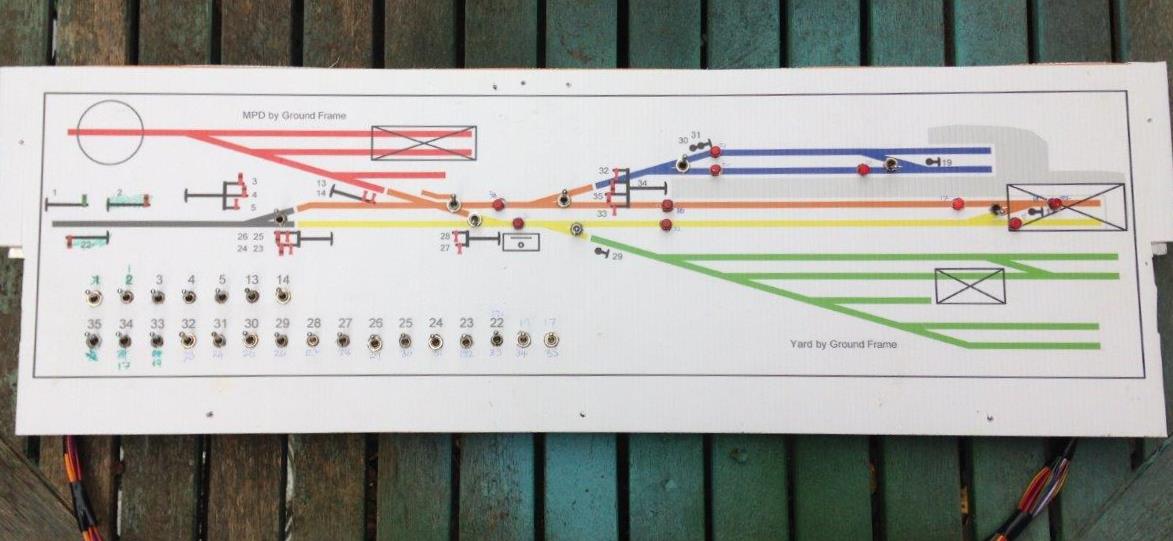
The control panel deals with all of the signals and turnouts that the cabin will have controlled, with local ground frames (which will be located on the boards locally) to be used to control the goods yard and the MPD. The latter will be arranged such that it can be located either to the front or the rear, to allow some flexibility in operation.
I have got to the point where the full extent of switches have been wired in and I am just completing the jumper leads. I took a lot of care to plan the wiring prior to any construction – despite the locos being DCC controlled, there are an awful lot of wires. This is because I have stuck with traditional control for the turnouts and signals. There is further complication as a result of the desire to incorporate some bells and even a block instruments (well maybe, at the moment it is just the wires!). So in all, there are 90 odd wires doing something or another on the layout.
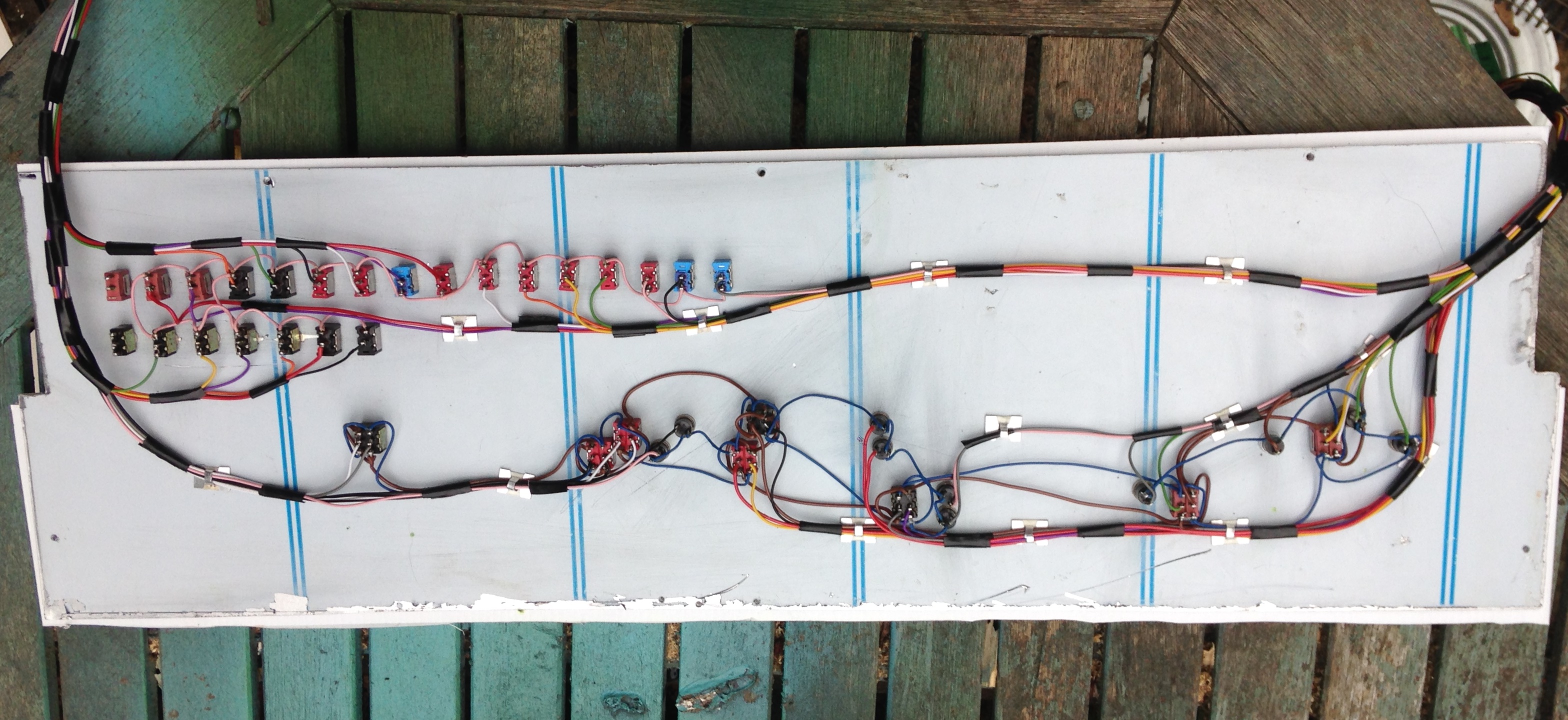
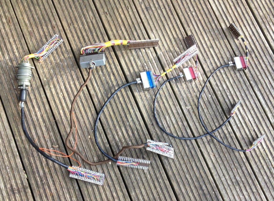
Somewhat in contrast to Portchullin, I have sought to keep the wiring as tidy as possible; everything is neatly collour coded and even labelled (to be fair it was labelled on Portchullin, but in a non colourfast ink………..!). I am hoping that this will make the wiring easier to debug at the start of the matter and repair if it does get damaged.
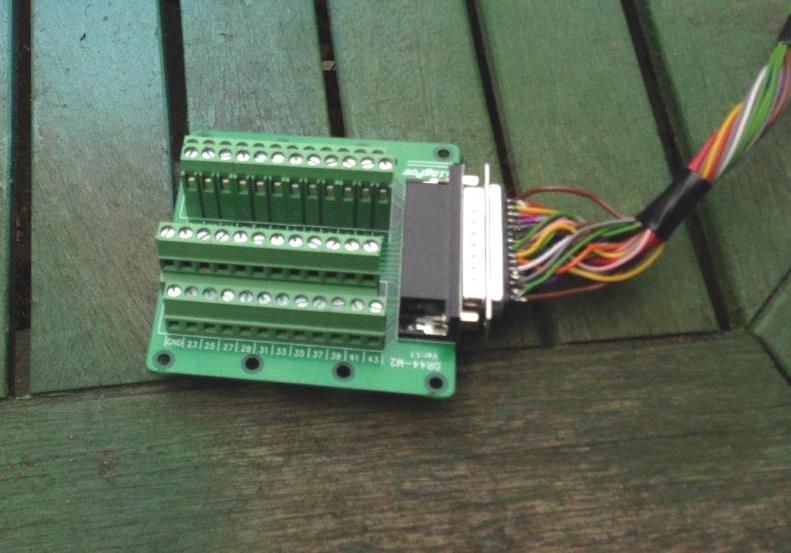
I am proposing to use a variety of connectors between boards and to the control panel, including this rather nifty varient of the D-sub range that is wired directly onot a cheeseblock wireless connector. Available to a variety of types from ebay including from this seller.