Blog Archives

2P or not 2P, that is the question
How often do we look to start a project as it will be relatively simple to do before we tackle something more challenging but then find it wasn’t quite as simple as we thought? Well, for me this seems to be a recurring theme and this is one such example; albeit one that is largely self inflicted!
I wanted a fairly simple loco to have finished quickly and I thought the Hornby 2P would make a simple wheel swap conversion. And so it would be if I could accept a few compromises – my problem was that once I started it, I came to the conclusion that I couldn’t.
The first problem is that whilst the loco body had an upgrade within the last decade or so, the tender was not only from the last millenium, but not even near the end of it! It is very crude and the thickness of the parts suggests that it was made from left over armour plating from a Dreadnought. It had to go, but that story will be for a future blog post. Instead, we move to the second problem – having decided I could tolerate the narrow frames and crude bogie, I changed my mind. To be fair to myself, I blame Rumney Models for introducing some rather nice LMS loco bogies and I could not very well fit one without also attending to the wider chassis. So, an order went in to Comet for their chassis and my simple quick project ceased to be!
Of course, I then decided to make it a tad more difficult for myself by deciding to include CSB suspension. Actually, I don’t agree with that (admittedly regular) accusation as I find that once it is set up properly – which with the High Level jig, CSB chassis are quite easy. So once this was set up it was time to set up the chassis – I did this by initially laminating the two faces of the coupling rods together “in the usual manner” but I deliberatly used a high melt solder. This enabled me to also then solder the two coupling rods to each other with a lower grade of solder without the fear that the laminate would come unstuck later. This was done prior to the opening out of the crankpin holes – which i did on the piller drill so they were formed as a perfect pair. This is then where we got to:
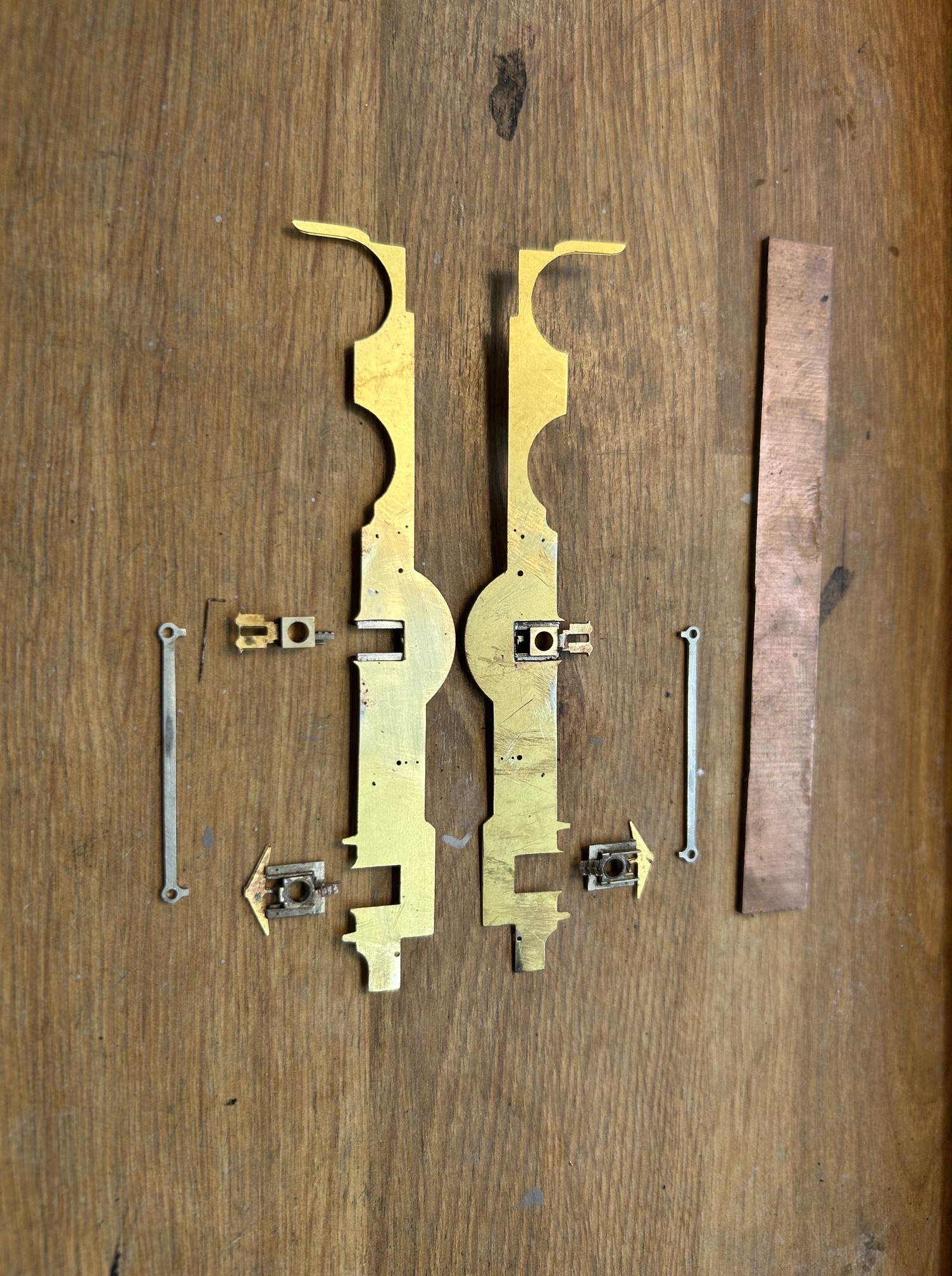
You will see that I have used High Level hornblocks but have attached the cosmetic springs to them. Not my idea but a really neat solution to acheive one of my key expectations of a chassis which is that the wheels are capable of being removed. I do this so that I can get the wheels in and the chassis operational at an early stage but can then remove them later whilst the the remaining detail is added without flux leaking onto the steel components or damaging the wheels. It also has the advantage that they can be removed for painting and future maintenance.
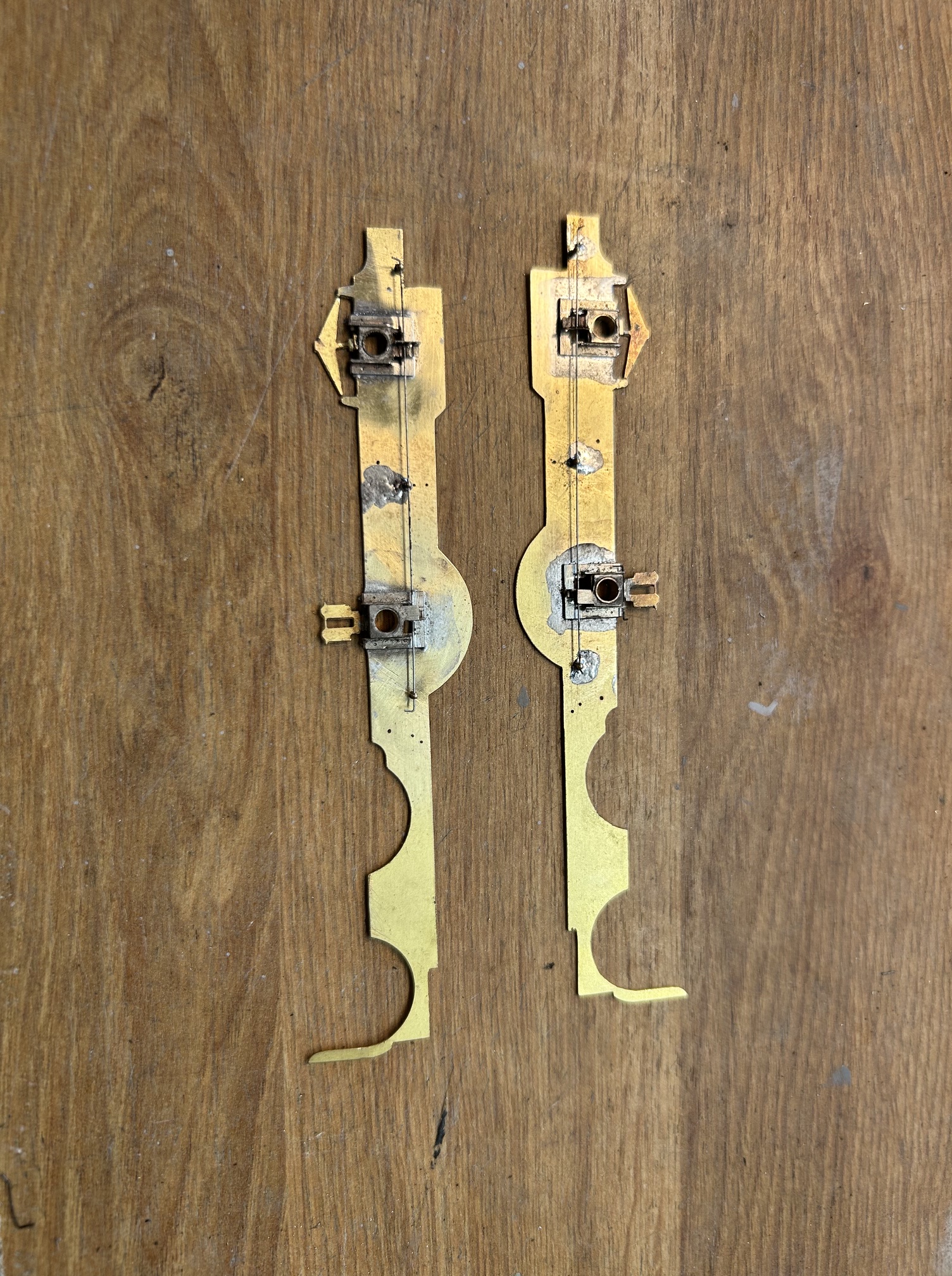
CSB stands for “continous springy beams” and these can be seen in the above image as the wire that it spanning from anchor posts on the frames and across a tag on the top of the pair of hornblocks. They act about half way between compensation – because as one side is defelected, it pushes up on the other side – and also springing because the wire also gives a little. Once set up, they are very effective and if you decide that the height is not quite right, the tags can be adjusted to raise or lower the height of the axlebox and the wire thickness can be changed to make them softer or harder to suit.
The axlebox spacings was achieved by way of the use of a chassis jig which I will do a post on in the future, as it is well worth understanding. Having set out the axleboxes, the two frames could be assembled (again using the chassis jig to ensure the axles are perpendicular to the frames. We now have the basics of the chassis made.
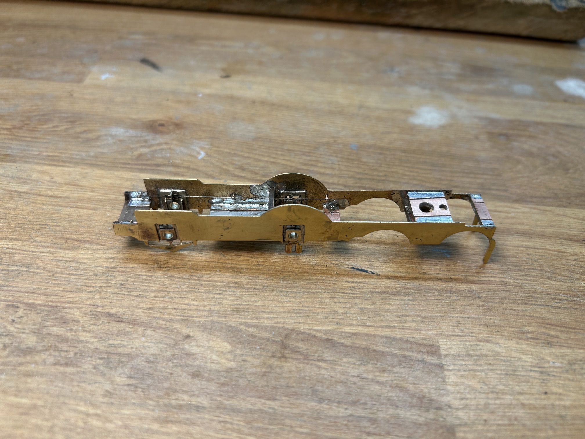
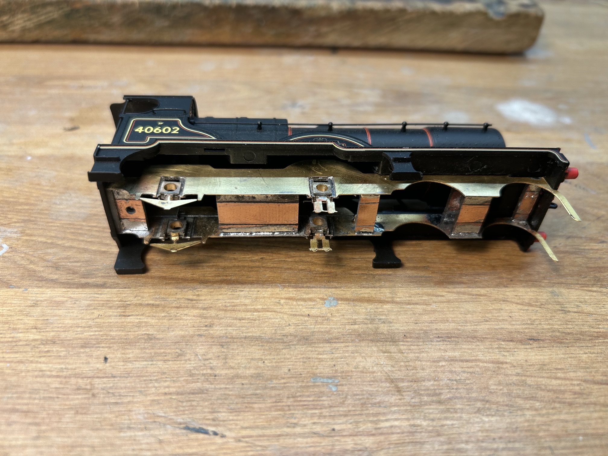
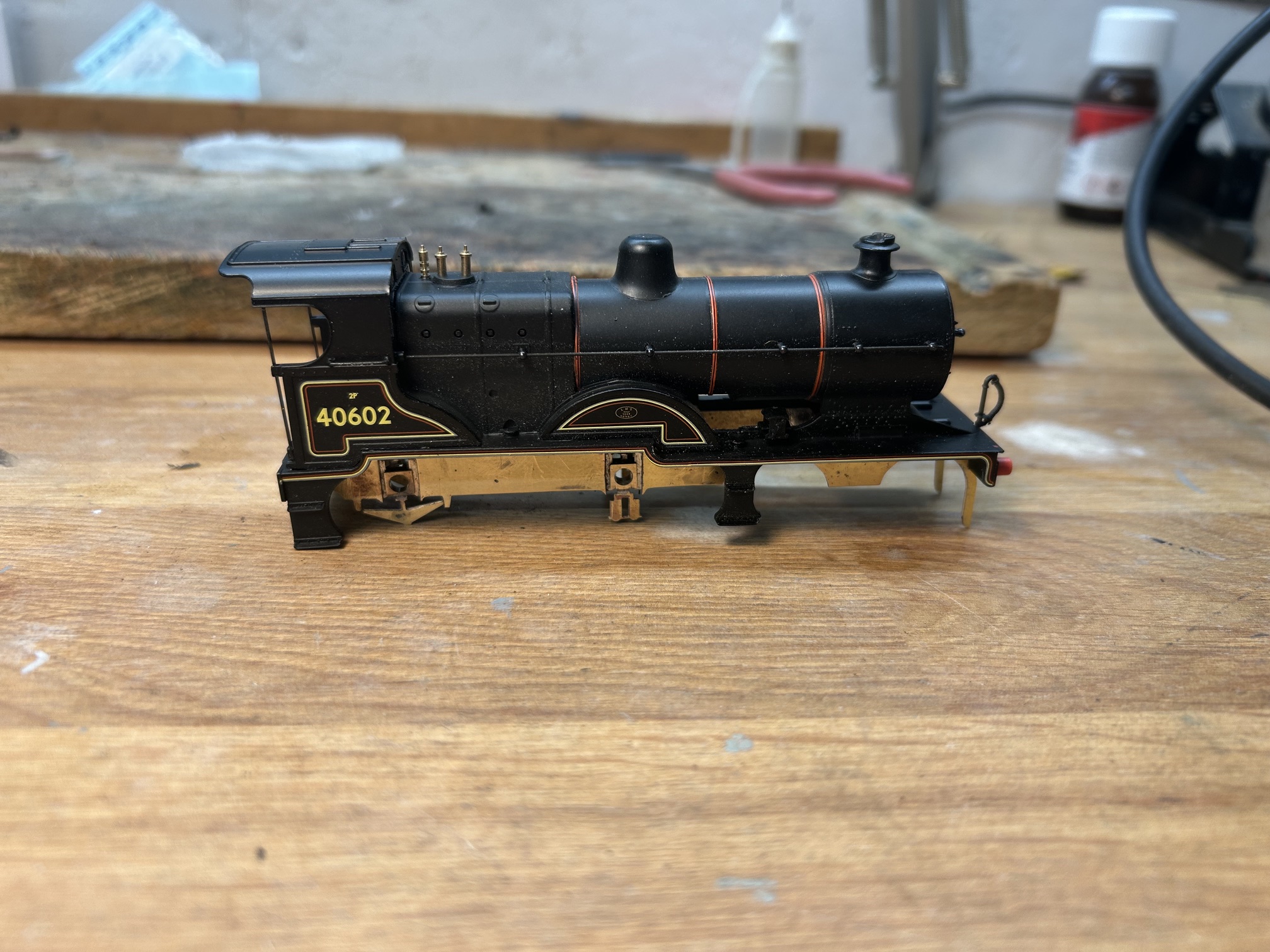
And now, by adding some mounting points that matched the screw holes in the Hornby body, it could be fitted in place and at last it is beginning to look a little like a locomotive (admittedly only a very little…….).
Next comes the wheels and following comments on the Scalefour Society forum, I have modified my technique for doing these. This is intended to get the wheels on the axles more squarely. What is not immediately obvious until you look is that the hubs of wheels project beyond the rims of the wheels, as can be seen below:
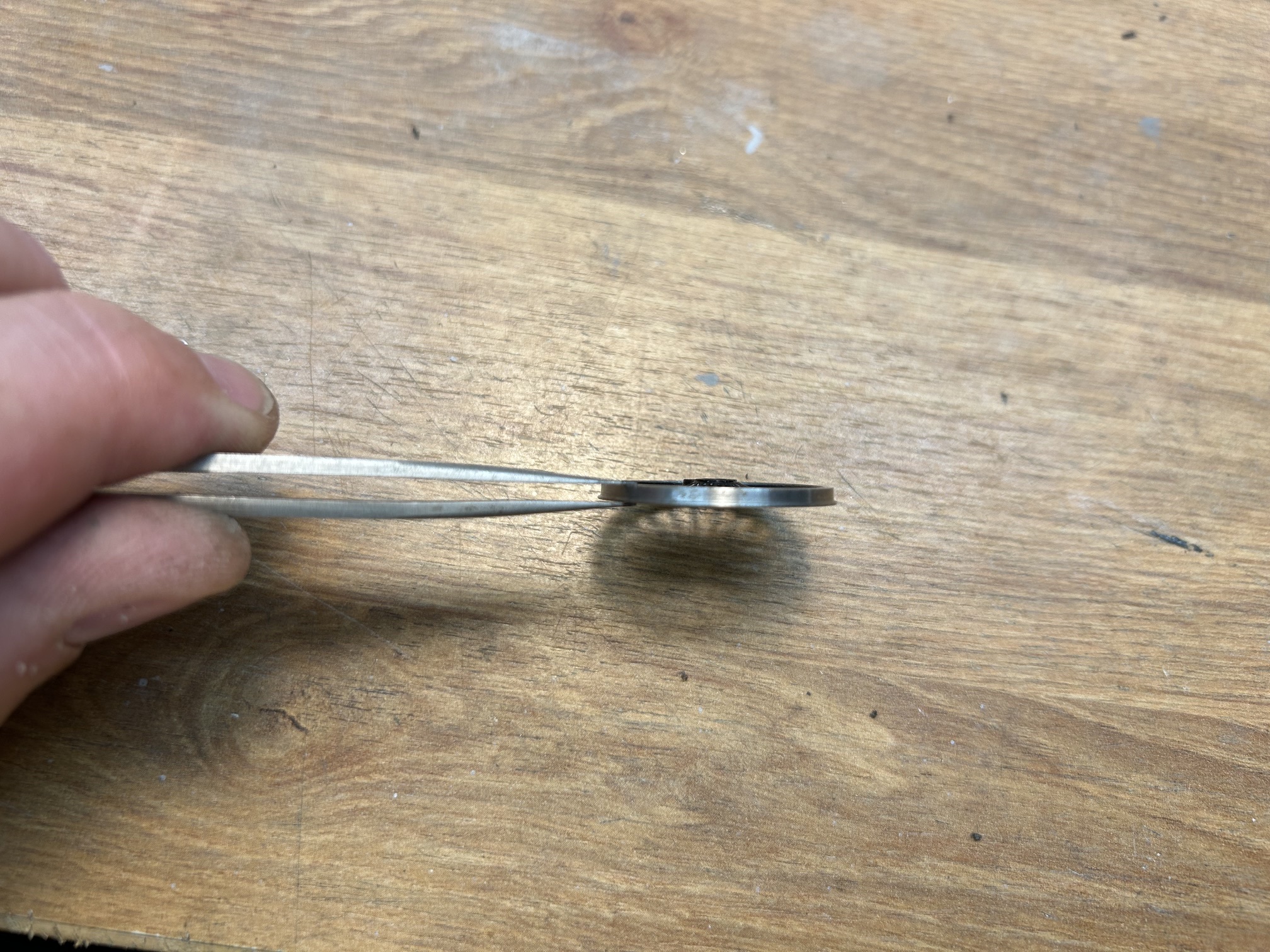
This means that the wheel press is actually only pushing on a small part of the wheel and more than that, one close to the axle. With large diameter axles in particular, even a small error here gives a significant change of gauge which can lead to derailments and also a waddling of the loco as it travels down the track. The trick alluded to on the forum was to adjust the wheel press so that it presses on the rim of the wheel by attaching a shim of plasticard.
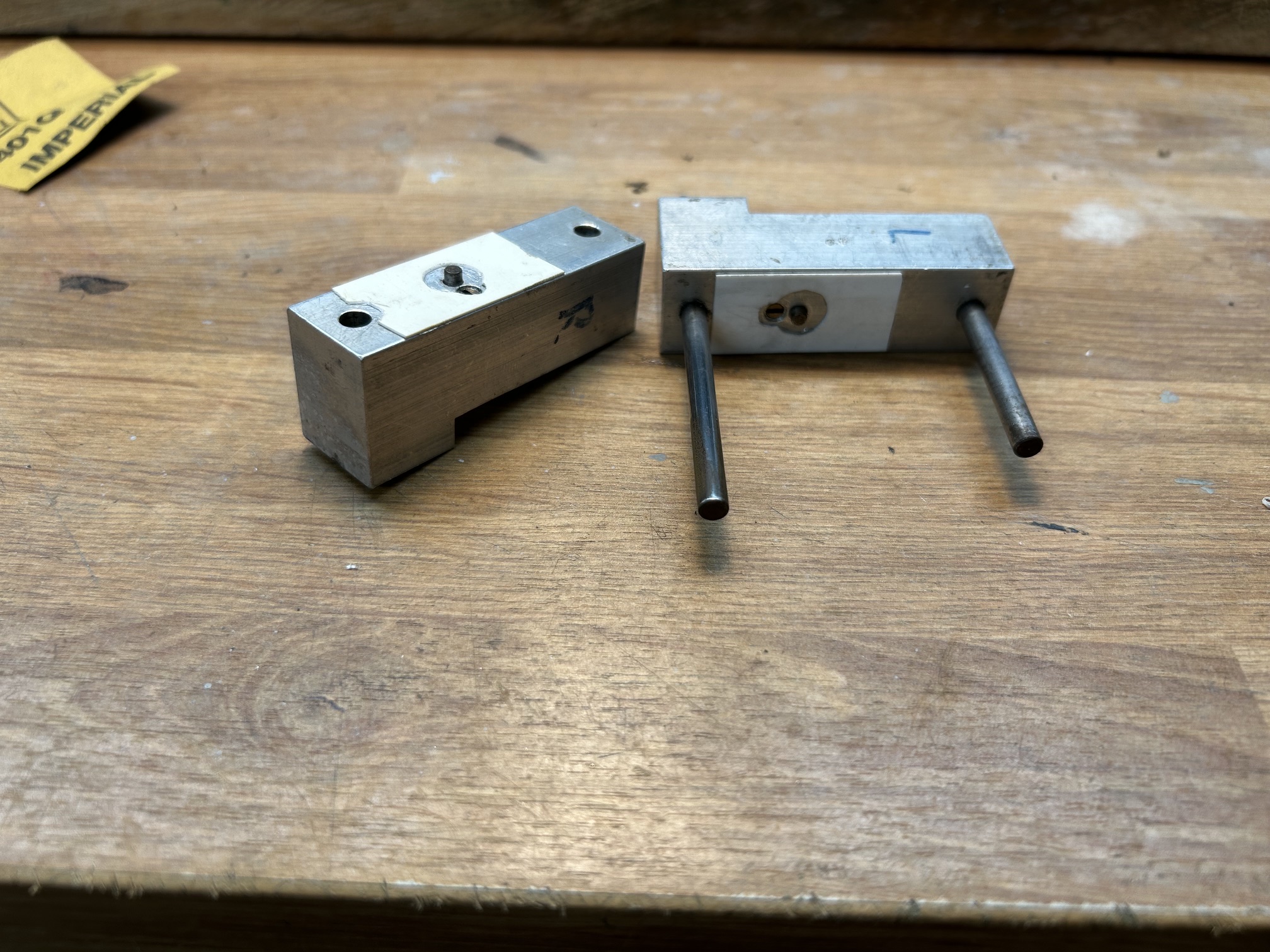
I am really pleased with the impact that this simple change has had, the wheels are on much more squarely despite being the largest drivers I have fitted.
Fitting the motor, with a High Level gearbox, got me to a working chassis. I am particularly pleased with this one as it is so smooth.
However, having got to a neat working chassis, I obviously had to unpick some of the work that I had made, as I will allude to in the next post.
A Ransome & Rapier Crane
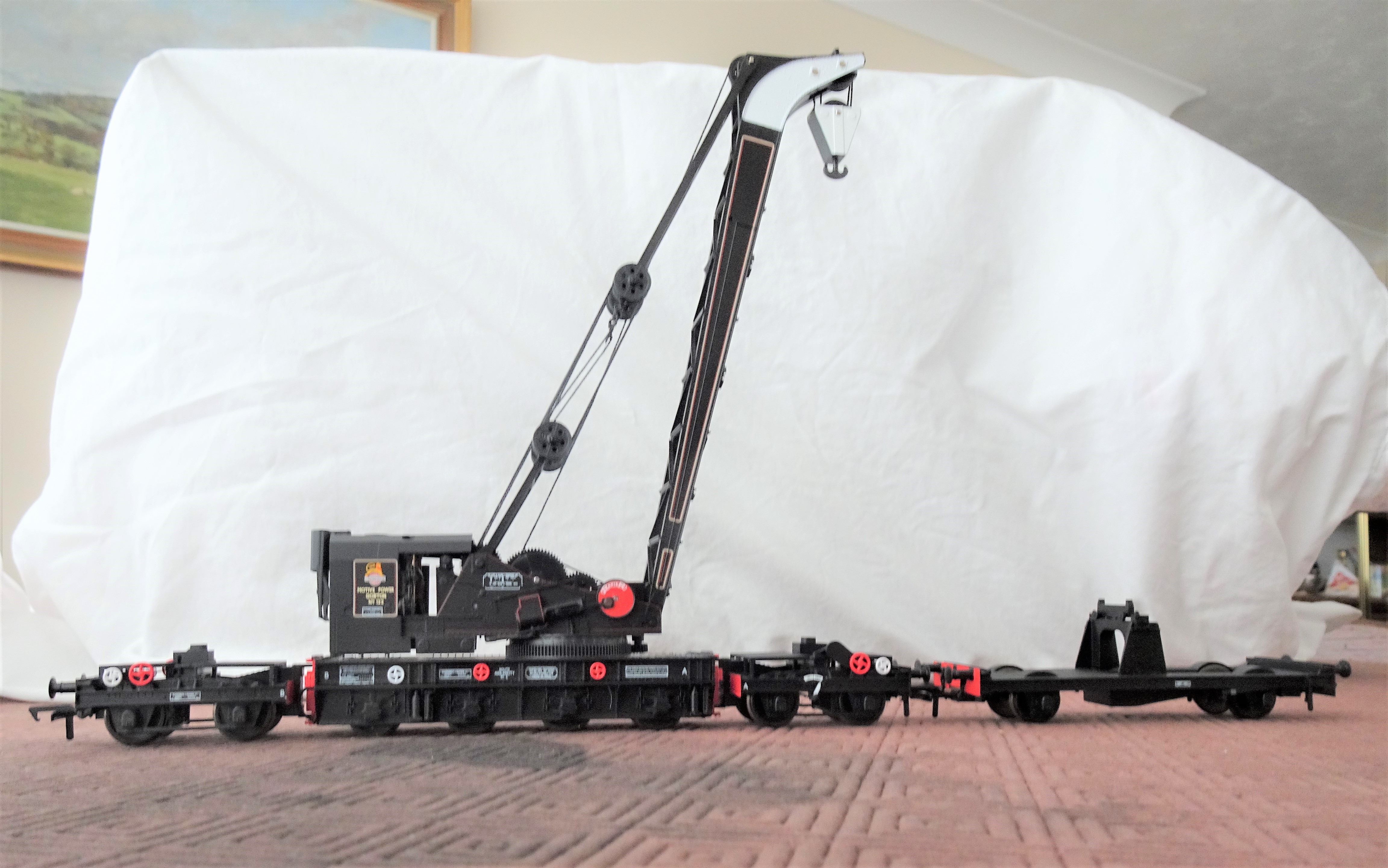
Readers of this blog will recall that my father has a significant interest in breakdown cranes; he has published a series of books on them and is the honoury president of the Breakdown Crane Association. As a result of this, a few years ago, he took a call from Bachmann when they started to research the possibility of filling a gap in the ready to run scene for a accurate breakdown crane. He delighted in being sworn to secrecy on this until the model was announced and now, some five years later, it has finally arrived on the shelves.
So after a somewhat unsatisfactory retail experience with Rails of Sheffield (which I won’t be repeating, there are plenty of other retailers out there), an example of a Ransomes & Rapier 45 ton crane arrived not much more than a couple of hours spare so that it could be parcelled up in its Christmas wrapping for my father. Now that it has reemerged, it is time to take a look at it.
Prototype
The prototypes originate from the early years of the last world war and were initiated by the British Government; in part in anticipation of a lot of emergency repairs being required following enemy action and also for use on the continent once a toehold had been achieved. Initially a total of six were made, going to the SR and GWR but subsequently a further order of nine were made, mostly for the military but with a couple for the LNER and another for the SR. The example I bought being from the latter batch, being initially based in Gorton on the ex GCR system.
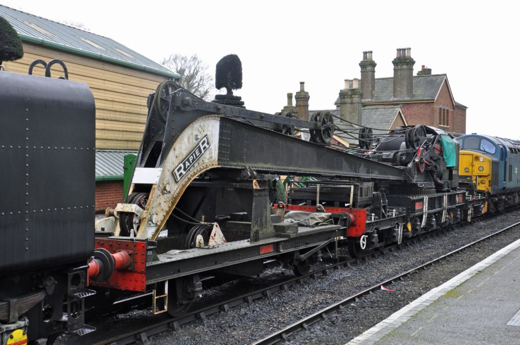
There were detail differences, with many of the railway company vehicles utilising standard components from their eventual owners. The valve chests for the cylinders moved to the exterior in the later batches and the operation of the loading of the relieving bogies became hydraulic latterly. The biggest changes, however, related to the match wagons where there was both variety of arrangements of tool boxes at the time of building and generations of modifications thereafter.
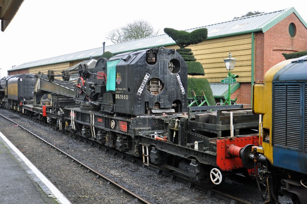
The cranes lasted until the mid 1980’s and a number of them survive in preservation, so if you want to see the real thing you might want to head to the Midhants Railway (on which the prototype photographs were taken and reproduced with kind permission of Carl Watson), the Bluebell Railway, the Great Central Railway, the North Yorkshire Moors Railway or the Swanage Railway. Below is a link to a video of the Midhants crane in action:
Model
The first thing you notice with the model is that it is some way from the toy train end of the model train market. The prototype is smothered in detail; with the fine bracing between the sides of the jib, the gear trains, axleboxes and flywheels all being a bit out of the ordinary for the ready to run market. Bachmann have had a really good go at this and for the greater part they have got it right – very few could model a crane as well as this. There are, however, several compromises made to enable them to be operable. This particularly shows at the bearing points at the head of the jib (exposed metal when they shouldn’t be visible) and on the crankpin nuts to the flywheels (way too big and hexagonal). I understand why this was done, but it sticks out to my eyes! Some touching in of paintwork will help (but not be perfect) and the replacement of nuts with something more subtle should be possible.
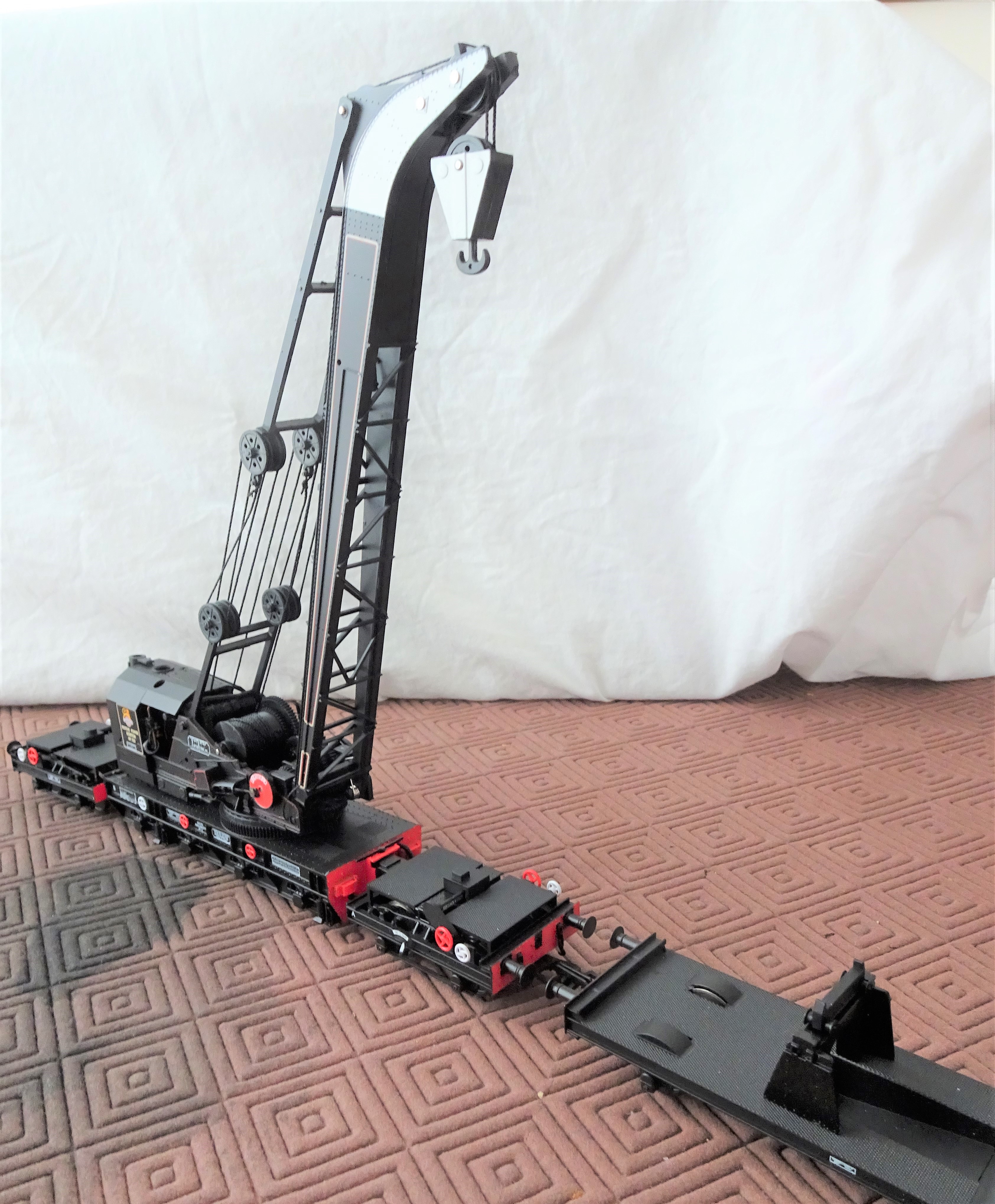
The detail is very delicate and the model needs to be handled very carefully as a result. Even the most careful (and I don’t count myself in this group) are unlikely to keep all the detail in place on any model that does not merely sit in the display cabinet. With a recommended retail price of £250, substantially more than any other product that is not filled with motors & electronics, it is doubtful that too many will end up in the hands of children – maybe that is just as well!
The model I bought, the early BR model in black – Bachmann ref SKU: 38-802, has a match truck without tool boxes. This is correct for the specific crane post the early 1950s but what is not is the missing insides to the splashers. This seems to be a compromise to accommodate OO wheelsets without making the splashers excessively deep. It is easy enough to fill in the open spaces if you model in one of the wider gauges and it will make a big difference.
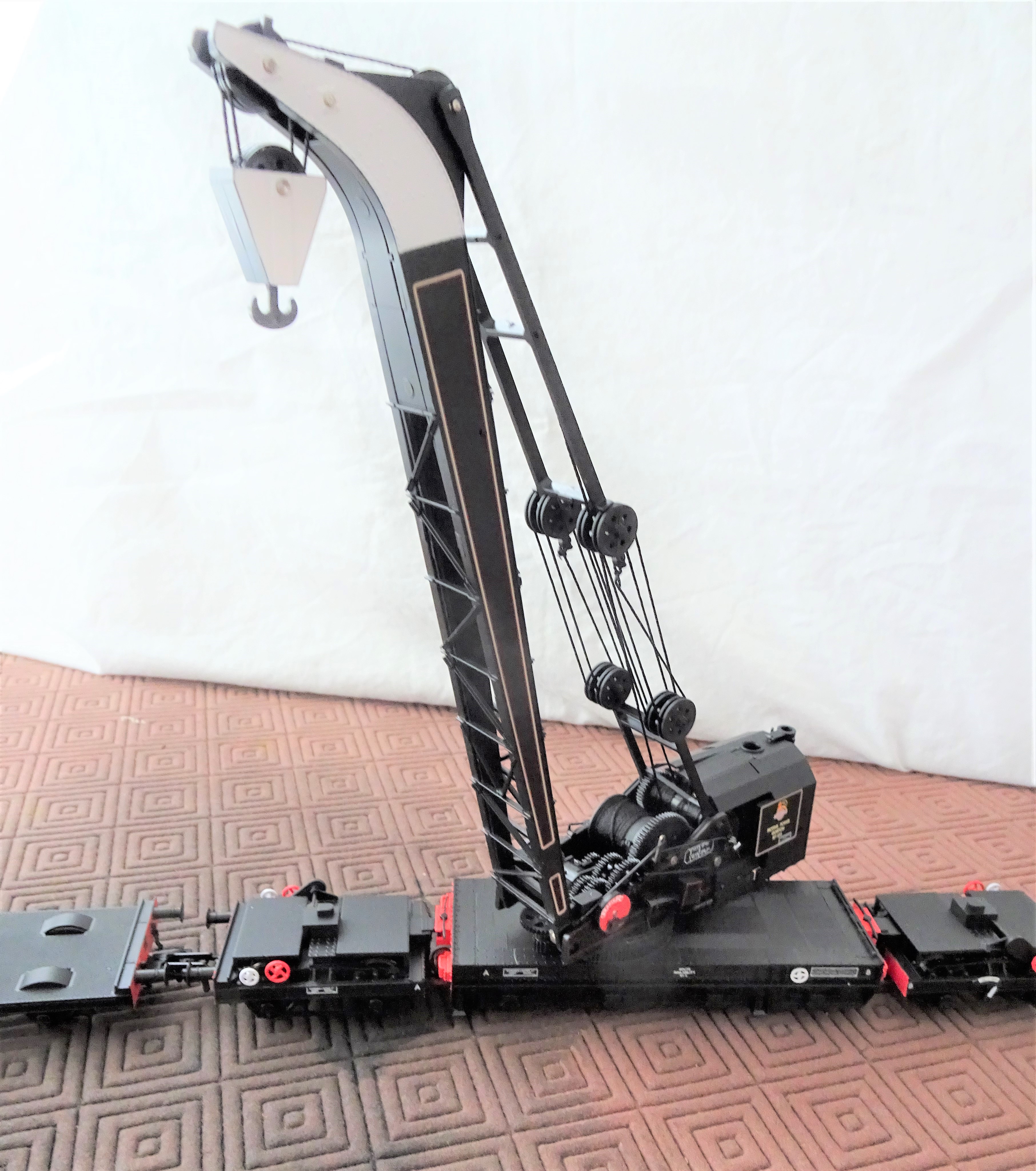
The painting and livery is particularly fine on the model. Even better there are some exquisitely delicate etched plates that can be applied on top of some of the plates. I suspect I see the shadow of Mr Hanson on them.
Options
It looks realistic to get P4 wheels into the crane underframe and definitely so for the runners/match wagon. I would, however, be concerned as to whether a four axle vehicle could survive all but perfect track in P4 and how many of us have that? I suspect that it will all be very tight too, so some pretty large radius curves would be needed if a P4 model can get around them. Of course I will have a go, but it is not high on the to do list at the moment!
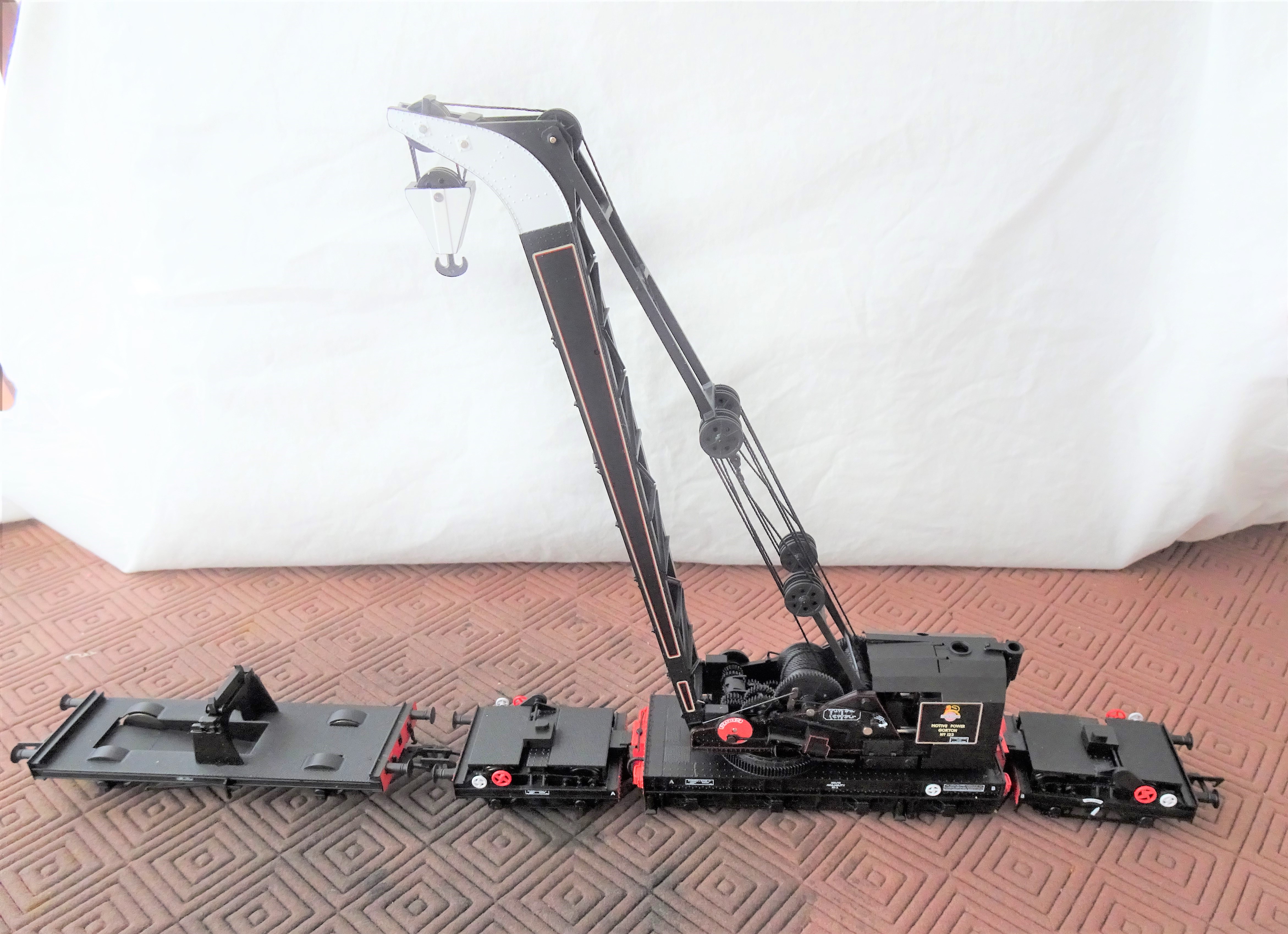
I think it is only a matter of time before someone looks at trying to motorise the crane. I think I will say good luck to them! Getting micromotors in might be possible for at least movement along the track but that still leaves slewing of the crane deck, raising of the jib and raising of the hook to go – getting another three in looks pretty difficult to me! The model does include internal hand operated mechanisms for the latter two movements – there are access panels that pop out to reveal a socket to receive a hand wheel. Thus, it is realistic to stage scenes, but not (in my eyes anyway – I really do look forward to someone having a go!) to make a fully operating model.
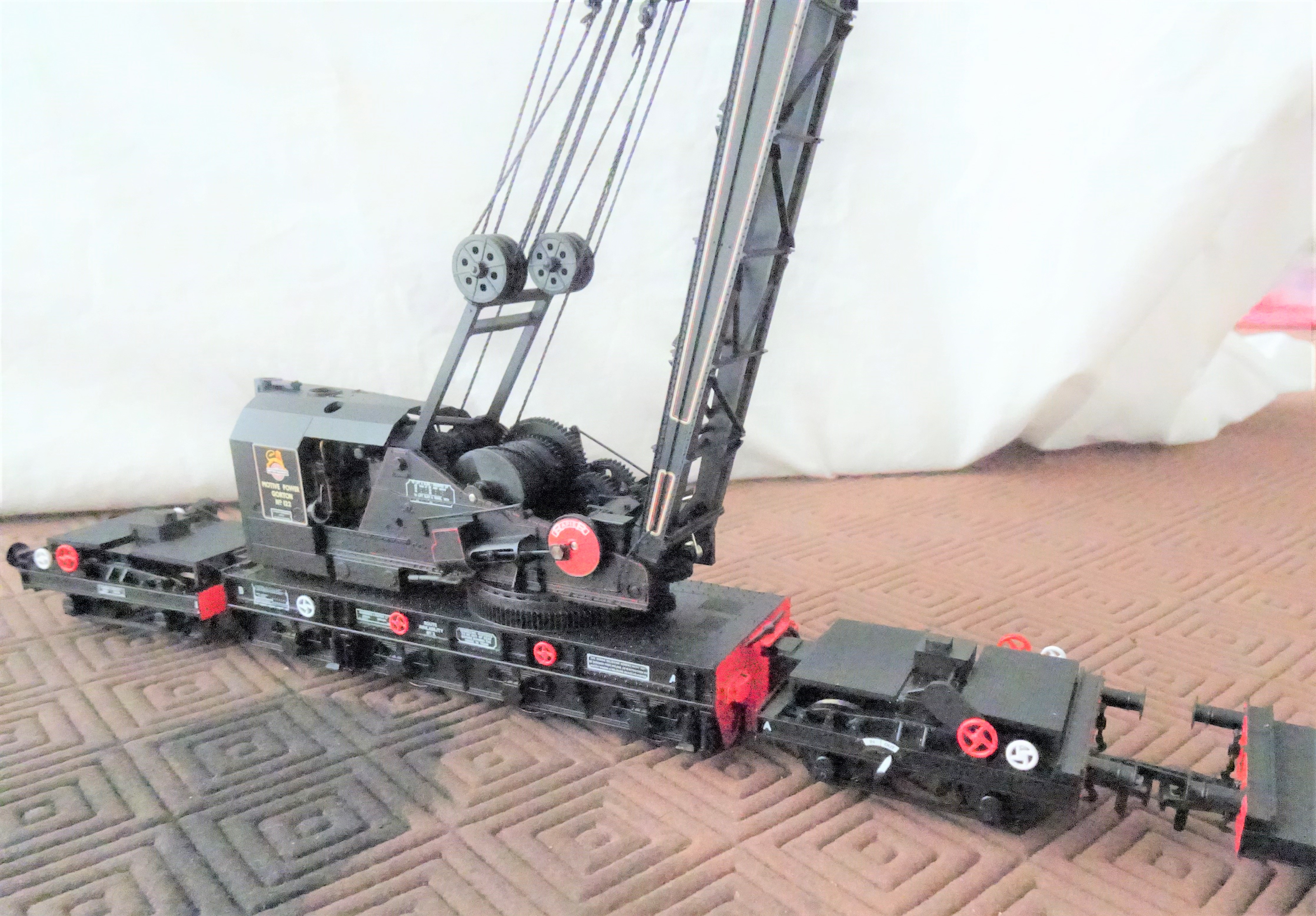
What is a must though is to add the paraphernalia of clutter the real cranes acquired in operation. Photographs show that they typically attracted lumber sections, jacks, chains and tarpaulins as if they were magnets. Cranes, not being front line stock in the public eye, tended not to suffer repaints very frequently and as they stood outside, they did weather and pick up corrosion spots. So any self respecting modeller needs to do something about how clean they look.
Although there is a very long in the tooth model crane from Hornby, it is somewhat of an uncomfortable marriage of several different cranes (the really old Hornby Doublo diecast version is better but quite crude), so does not cut the mustard. There are a limited number of kits for other cranes – notably the D&S Models Cowen Sheldon 15 ton breakdown crane (an example of one might grace these pages eventually!) but these are full on kits. Thus Bachmanns cranes are not only attractive models in their own right but they have a field fairly clear of competitors.
If you want the book on the prototype you need volume 2 of my father’s book – at present it is out of print but it is hoped with a bit of pressure on the publishers, Crecy, they can be persuaded to do a further print run.
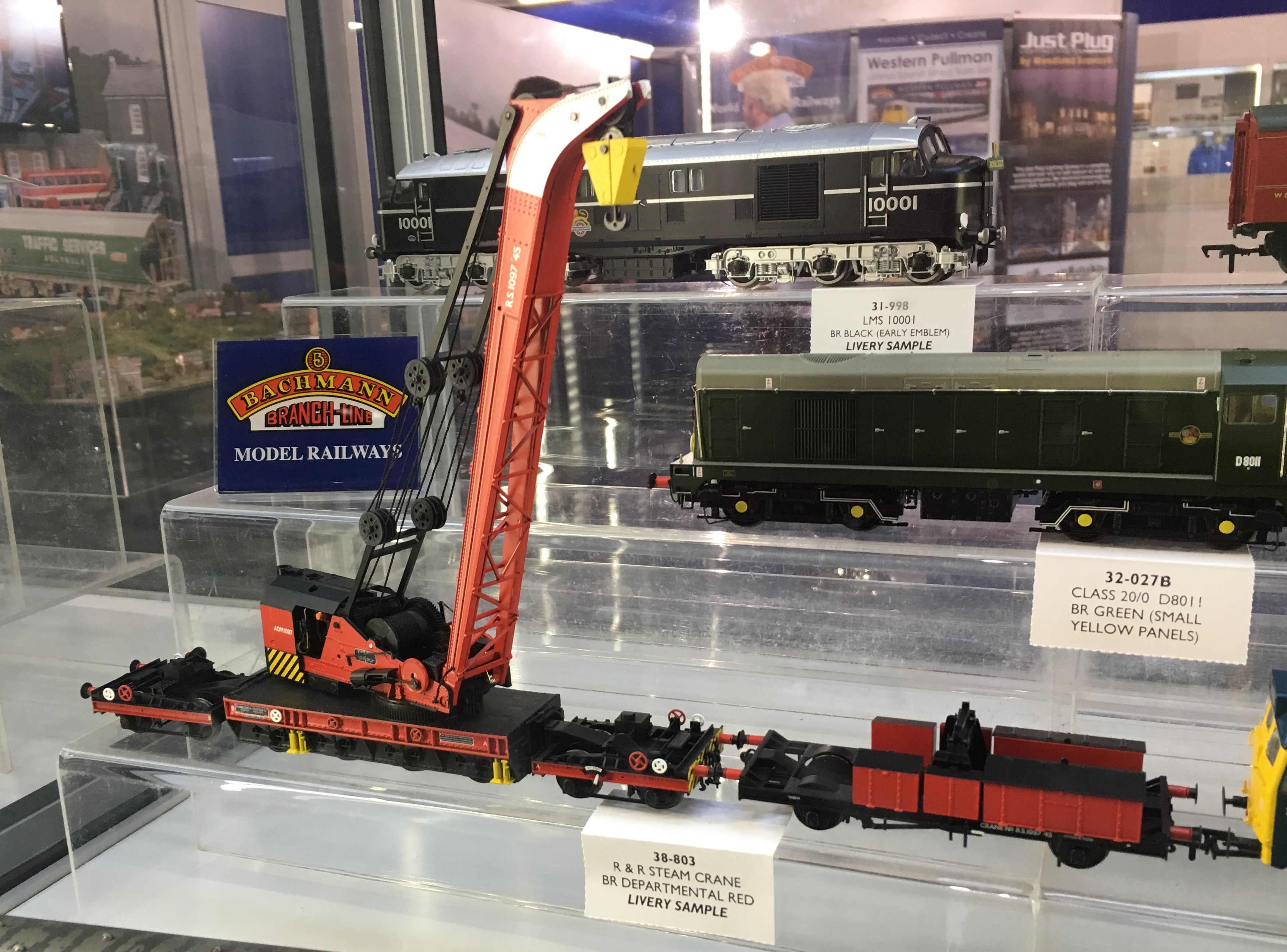
The Bachmann crane is presently available in an SR livery, a GWR livery and then a pair of BR liveries – the 1950s livery shown above and a later gulf red livery. An example of the latter is below:

Gresley Buffet – Part 4 Finished!
…..but, before it was counted as finished, it needs to be doing the job it was designed for – buffeting. And that means it needs to be populated with people.
Regrettably few modellers, even finescale modellers, actually put people in thier coaches (and sometimes in contrast to platforms which are stuffed with them!). This is a shame as they do make a difference to even a fairly casual viewer. At a show recently, a dad and his son who were probably not modellers spotted the people in my coaches instantly. I’ll take that as proof of the point!
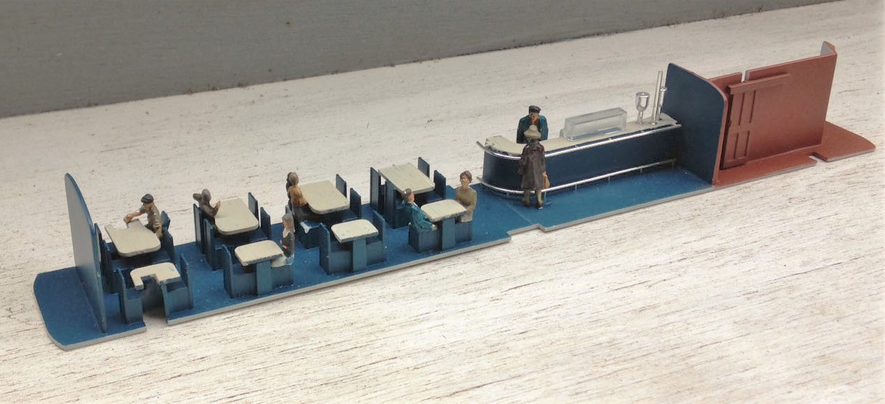
As is common with rtr coaches, the seats are moulded in place such that there is no room for the little peoples legs, so some severe amupation is required! In the case of Hornby’s buffet, the seats are also modelled pushed tightly underneath the tables – which has meant that the backs to the seats or the lip of the table also needs to be hacked away a bit. As all of this surgery occurs below the waistline of the coach, it is not visible from outside so your Dr Crippins’ tendancies will go unnoticed!!
Next up was to paint the exterior where the new plastic was cut in and here I had some problems. I was warned by Brian of Shawplan that I should paint the whole side when I repainted the new sections but I decided not to follow this advice – something I now regret!! So having masked up theadjacent areas and sprayed in only the affected sections i found that the grey that Hornby used was notably bluer than that provided by Precision Paints. The first attempt at repainting had the colours sticking out like a sore thumb and even on the second attempt, with a dab of blue in the mix is not perfect but is just ok underneath the grime. So, if you are proposing to do follow this build follow Brian’s advice, not mine!
Once a couple of new windows were cut into the reshaped windows in the kitchen area of the buffet car, it was necessary to weather the vehicle. These buffet cars were notorious for being really tatty by the 1970’s; partly because the paint supposedly was prone to debonding from the underlying teak but also because the automatic washers were not good at getting into the corners of the panelling. After an overall spray of dirt to tone down the colours and another to represent the brake dust and track muck, I used two techniques to represent the weathering on the panelling. The first was to spray the whole coach with a mist and once it had started to dry a stiff artist’s brush was dipped in thinners was used to remove the bulk of the paint. The areas that it does not come away from are the nooks and crannies around the panelling; the same areas that would have retained the dirt in the real things. I to find, however, that the margine between where the paint has been removed and not can be a bit stark, so I used a second technique to both hramonise this and also acceptuate the effect. Using a heavily thinned dirty black paint, run a brush over the whole of the sides – the paint runs to the corners and achieves the same effect. It pays to be brave with this as the wetting effect of the thinners makes this initially look much darker until the thinners have dried off.
And this is what the finished article looks like………
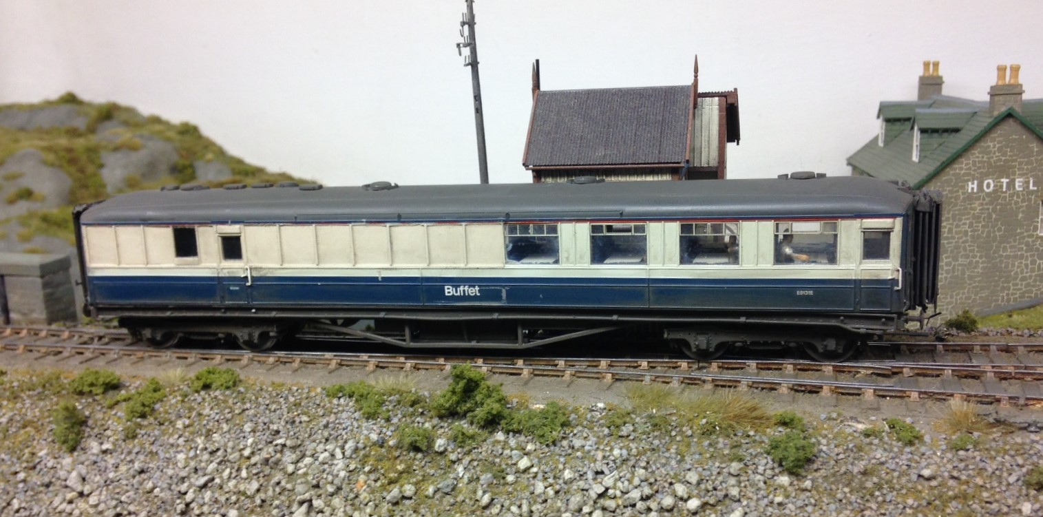
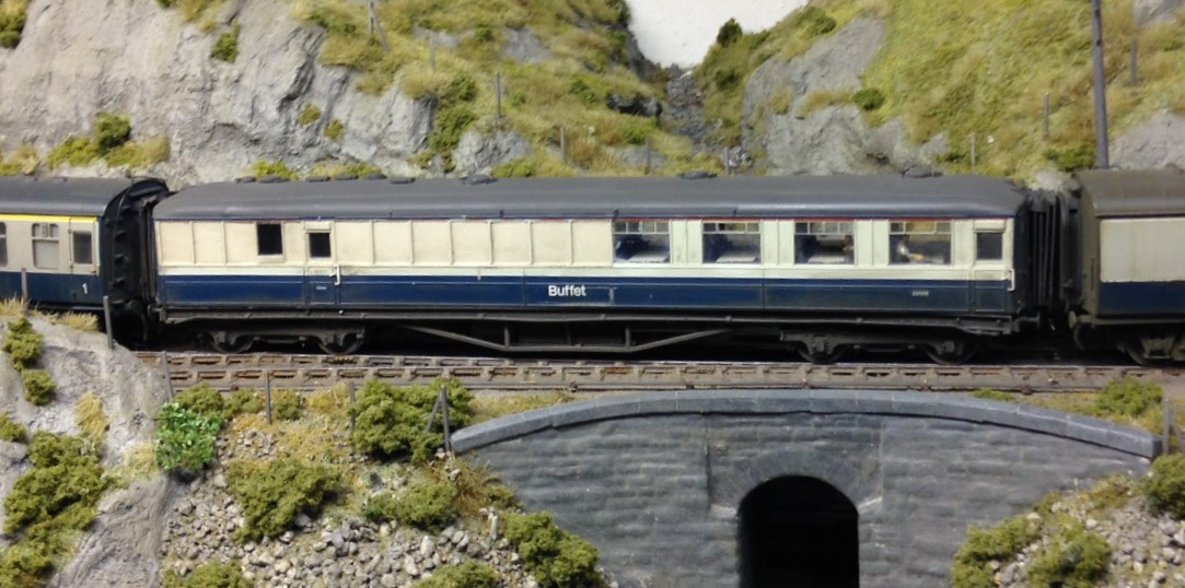
So thanks Hornby for supplying the model in the first place and the inspiration to do some plastic surgery. Whilst this write up may have lasted some months, actually this was quite a quick conversion – the basic surgery on the side was only 4 hours – so why not have a go?
Gresley Buffet – Part 3; Corridor Connections
I guess that it is pretty difficult for the RTR manufacturer to take a stab decent corridor connections because they have to design for toy train set curves and clumsey hands but it is a weakness of all proprietary coaches. Hornby’s buffet also seems to have overly skinny corridor connections and most noticeable they are mounted too low – they should finish at the meeting of the roof with the ends.
Whilst it is possible to simply slice off the connections off and move them up, I chose to remove the and them with some produced by Comet – as this is an LNER vehicle, you need the Pullman type. The core of the operation of the corridor connections are the bellows which are formed with a pair of sheets of fairly stiff paper. These have slots cut to half their width and are then folded into a concertina shape, with the slot between the folds. Two such pieces are then offered up to each other, with the slots opposing and these then slide over each other as shown in the first picture.
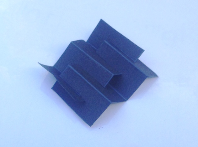
To create a concertina bellows like this.
Thereafter, the etched end plate is attached to one face. Whilst not provided in the kit, I formed a second plate from plasticard and affixed this to the other end. it is important to ensure that no glue gets on the concertina sections of the paper, as they need to be capable of compressing with minimal effort to correctly operate without derailing the carriage.
This is how Comet envisage that the completed connection should look like but I felt that the bellows did not look very realistic, especially from above where the crossing point is all too obvious. In practise, the top of these connections had a fabric roof and applying this dramatically improves the appearance of the connection and has the added advantage of providing some control to the operation of the connections which do tend to expand out and look rather flabby!
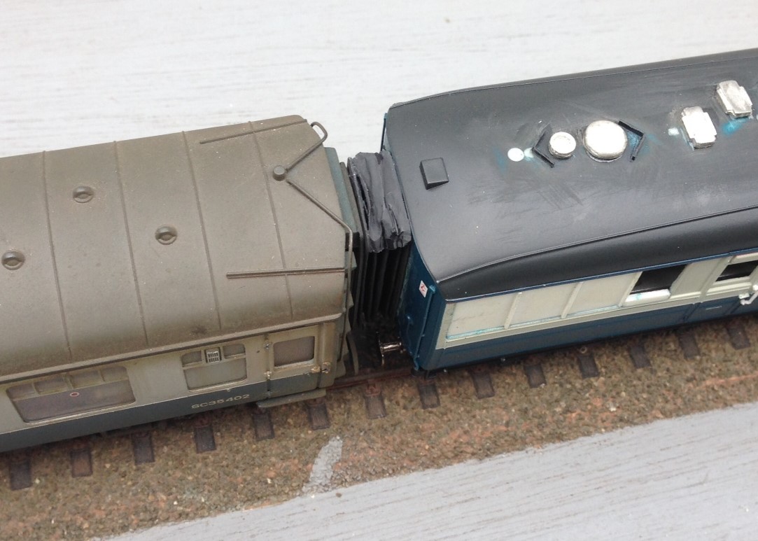
I dealt with this by putting the rain hood on the top of the connection, which is afterall prototypical (and makes a huge difference to the appearance as you can see). I did this in a manner that meant it acted as a restraint to the movement of the connection. I acheived this by only gluing it at the very back and front of the connection, so that the bellows could move unimpeeded but once they had moved to the required extent, the rain hood pulled tight and stopped them going any further. I found that doing this at the top was not sufficient as their movement continued at the bottom and they took on rather drunken appearance – however, this was solved by simply repeating this at the bottom.
Key to getting this to work was to use material for these restraints that was ultra flexible. I did think about trying silk but settled instead on the rather more mundale – plastic from a bin liner. This is remarkably thin but is still tough enough to hold the connections. A tiny dab of super glue at the front and back and then it can be laid onto. It is important not to sigh with releif for some time though – the stuff is so light that it blows away at the slightest. So this is what it looks like:
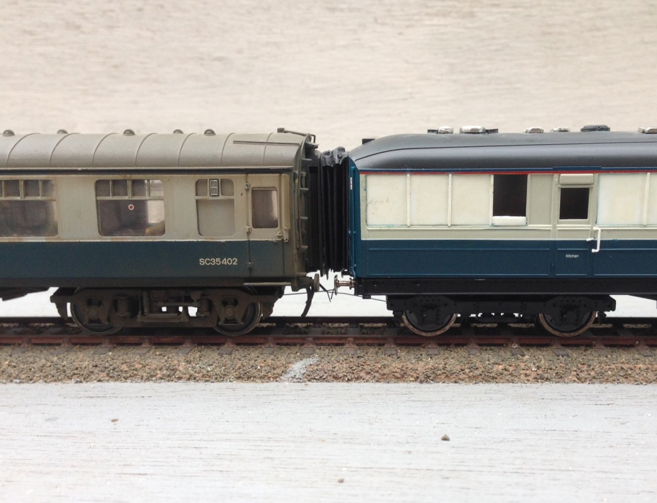
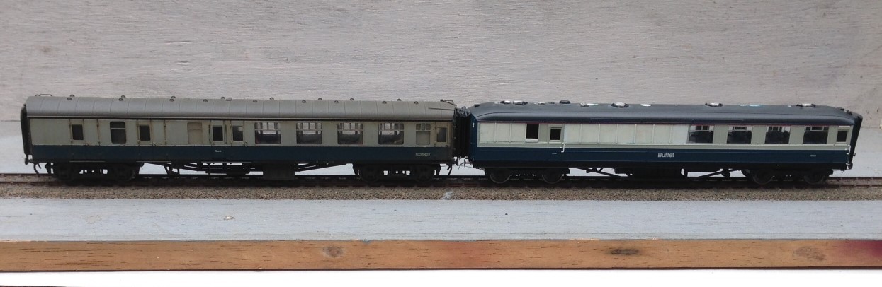
I think that I have still allowed the connections to be too big and if there were two together this would definitely be true but next to a rather skinny Bachmann corridor connection, I think they look pretty good (and a big improvement on the originals).
The Cruellest Cut – Carrying on with Hornby’s Gresley Buffet
The first task in dealing with ready to run vehicles is to work out how to get into them – not always as easy as it sounds! In this case, this is achieved by slipping finger nails between the sides and the underframe solebars; this releases four catches and the top pops off. The interior then slips out without bother but the glazing is a little more tricky as it is secured with some very gooey glue. Whilst this releases the perspex relatively easily, it was difficult to then remove the remaining glue – I found it best to do this by rolling it with a thumb and accumulating the residue on a scrap of paper but it was a pain getting it all off.
Prior to attacking the model with knife and blade, a sensible precaution is to protected all of the areas that are not to be cut with masking tape, which you will see I have done. This was effective but I did find that I dislodged a filler pipe when I removed it, so perhaps a slip of paper over these would be prudent next time.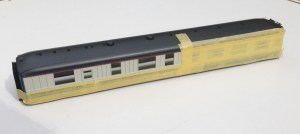
Then it was time to get cutting; I varied between using a razor saw and a scalpel to cut a grove by using parallel cuts but in both cases it is important to cut to the waste side of the finished line. I found that it was best to work to an existing bead line, even though when working to the saloon end of the coach the bead was the side of door jamb (this is where I found the knife best and I made sure this was one of the first cuts to be made) so that there was no stress on the thin piece of material. By the time the cutting had been finished the holes were quite big!
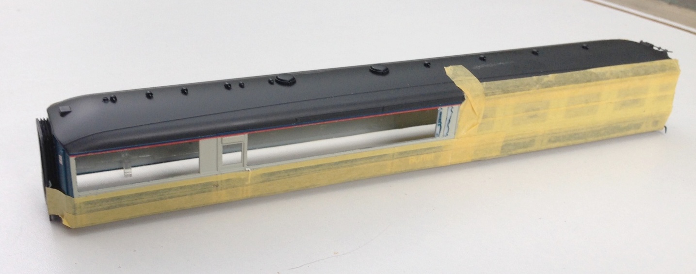
Nearly all the cutting done now; but the last panel to the right did also get cut away
It pays to dress the sides of the opening with care so that they are straight and square as this makes the fitting of the infill pieces much easier. These should be cut fractionally over large and then sanded back by small degrees checking regularly to determine if it fits and taking care to ensure that the square/straight edges are maintained. Once it fits, I let it into the hole and secured with butonone and then left it to cure for a couple of hours so that I did not disturb it when I subsequently fitted the beading. This was formed with 0.2 * 0.2mm microstrip and these needed to be set out with considerable care – aided by the use of venier calipers – to get them regularly spaced and vertical. Even the most minor of inconsistencies detract from the affect.
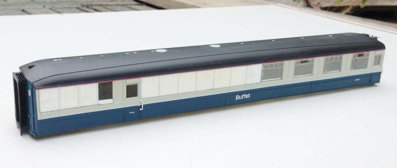
Replacement panels now in place, including a partial infill of the window by the door
Next up was the removal of the various roof vents and cowls as these too changed. I suspect that these were no consistent across differing vehicles and it is quite difficult to determine what goes where but I was assisted by some photographs from here. Utilising some of the vents salvaged from the Hornby model and also from Comet Models, the latter generally with their shields filed away as the roof views I have have straight flanges as shields – which I formed with brass strip as I though plasticard would be knocked off.
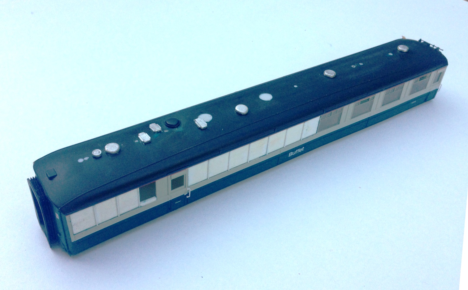
Roof vents in place, based on a photograph of the roof of 9132 at SRPS in the 1970s. I also noted that the alarm gear on the roof was at the other end of the vehicle in comparison to the Hornby model, so this is going to need to be cut away and recreated at the opposite end.
Dinner Time – A Gresley Buffet for Portchullin
Whilst my memories of the former HR’s line from the 1970s and early 80’s only ever had BR mk1s as coaching stock, there were occasional strays coming onto the line in the form of Thompson/Stanier full brakes and Gresley buffet cars. As I understand it, a pair of the latter were indeed the regulars on Glasgow to Inverness trains. So, wishing to enliven my passenger trains up a little on Portchullin, I thought that it was time that the punters had a buffet car to buy that notorious rock hard pork pie in!
Hornby introduced a range of Gresley stock some ten years or so ago and they represented a significant step forward in terms of quality of coaching stock generally and particularly in comparison with their predecessors. If I recall correctly there were some problems with the direction of the graining that Hornby quite quickly sorted out and the teak coaches look the part – especially as to do them oneself is a very challenging exercise. The only vehicle that they offer in blue/grey is the buffet and this is what it looks like.
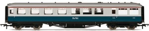
As with nearly all r-t-r models now a days, the finish is exemplary and at first glance it definitely looks the part, capturing the curves at the roof very well and it will stand out nicely in comparison with the remainder of the coaches on Portchullin. It is true that the panelling cover beads are a bit thick, which is not visible on the teak finished coaches due to the graining but is rather more visible on the grey here but as I am going to weather down this vehicle to a fairly battered condition, I am hoping this will fade to a lessor impact. Some commentators criticise the tumblehome being too slight and the bogies being subtly incorrect but I am struggling to see either defect so will ignore these points.
What I will not be ignoring, however, is the most significant problem with the model. These vehicles only made it into the 1970s because they underwent a fairly significant rebuild in the 1950s. Hornby have simply painted their LNER era model in blue/grey whereas the rebuild affected their appearance on one side quite significantly. Here is a comparison and you can see that three windows have disappeared altogether, the panelling arrangement on the near end is different and the roof vents were adjusted to accommodate the revised internal arrangement.
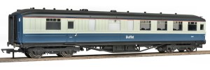
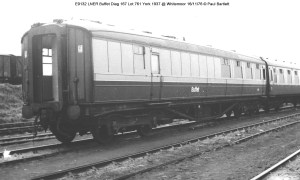
I have seen moans on the forums about this error and even moans from people at the people who are moaning. I make no criticism of Hornby at all; it is obvious that the revised tooling that would have been necessary to correct this would have made the model uneconomic. Therefore, we have to either accept it is as it is or pick up our tools to correct it. I make model railways to do simply that, make them and I derive the greater proportion of my satisfaction from building or modifying things – thus I simply see this as part of the pleasure!
So my next project will be a bit of plastic surgery on an old lady, to get her looking proper! I do not propose to do a full respray so it is not that difficult to do; so to both the moaners and the moaners at the moaners, I would simply encourage you to pick up your knives to follow suit!
Thank you to Hornby for providing the base model and also for the use of the colour photos. The prototype photograph is courtesy of Paul Barlett.
 highland miscellany