Blog Archives

Sam’s Trains – HR Open Wagon in 4mm/1ft
Somewhat out of the blue, I was bombarded by adverts for Etsy for something that I actually might buy (who knew that was even possible?). This was a small batch production of a HR wagon apparently being marketed as an ideal accompaniment to the Rapido’s Jones Goods. The pictures in the adverts suggested that it had captured something of the character of a highland wagon, so I allowed my loyalty to all things Highland to take a hold and I parted with £25 to see what it was like.
Sam is a youtuber who has created a niche for himself by producing caustic and generally very critical reviews of manufacturer’s products to gain views. How he has not been sued for libel for producing this clickbait I do not know, as a number of manufacturers must have thought about it given what he says about their products. As a result this, it is fair to say I was pretty concerned about what I might get – my conclusion is somewhere in the middle, some good points but there are plenty of errors too.
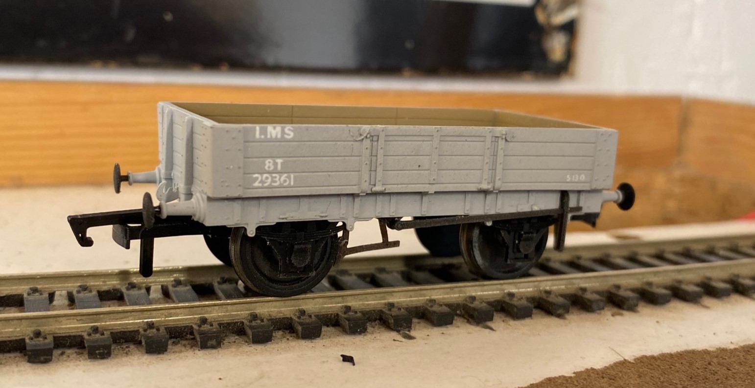
The model is of a Jones era open merchandise wagon to diagram 19. There are insufficient records to confirm when the prototypes were in production but probably in the 1880s upto the latter part of the 1890s. Similarly, withdrawal dates are unknown but it is probable that they lingered to the LMS era, but probably not by much. It was designed to be used for a variety of merchandise, often below a tarpaulin, but might well have been pressed into the carriage of minerals or even fish. Certainly, they were used for transporting sheep which was a seasonal (and substantial) traffic for the Highland. When used thus, they would be fitted with flakes to provide a higher fence to reduce the sheep suicide rate caused by jumping from moving trains.
The model is 3-D printed from resin and the quality of the printing is surprisingly good with almost no stratification lines. The resin seems to have some flex to it so ought to be durable and the wheels run relatively freely in the bearings. The resin appears to be self-coloured, with the chassis being in black and the body the intended livery (mine was in grey but there is a red oxide colour for the highland livery versions). This had led to some errors of colouring in that the trunnions and couplings should be black and the grey is too light as well as needing a bit of green to be a match for LMS grey. However, the lettering livery selected is the later LMS livery with small branding suitable from 1936 and is not strictly speaking correct even then as it has the wrong layout and an impossible wagon number. To be fair to Sam, he admits this is a “what if” prospect so if this floats your boat so be it.
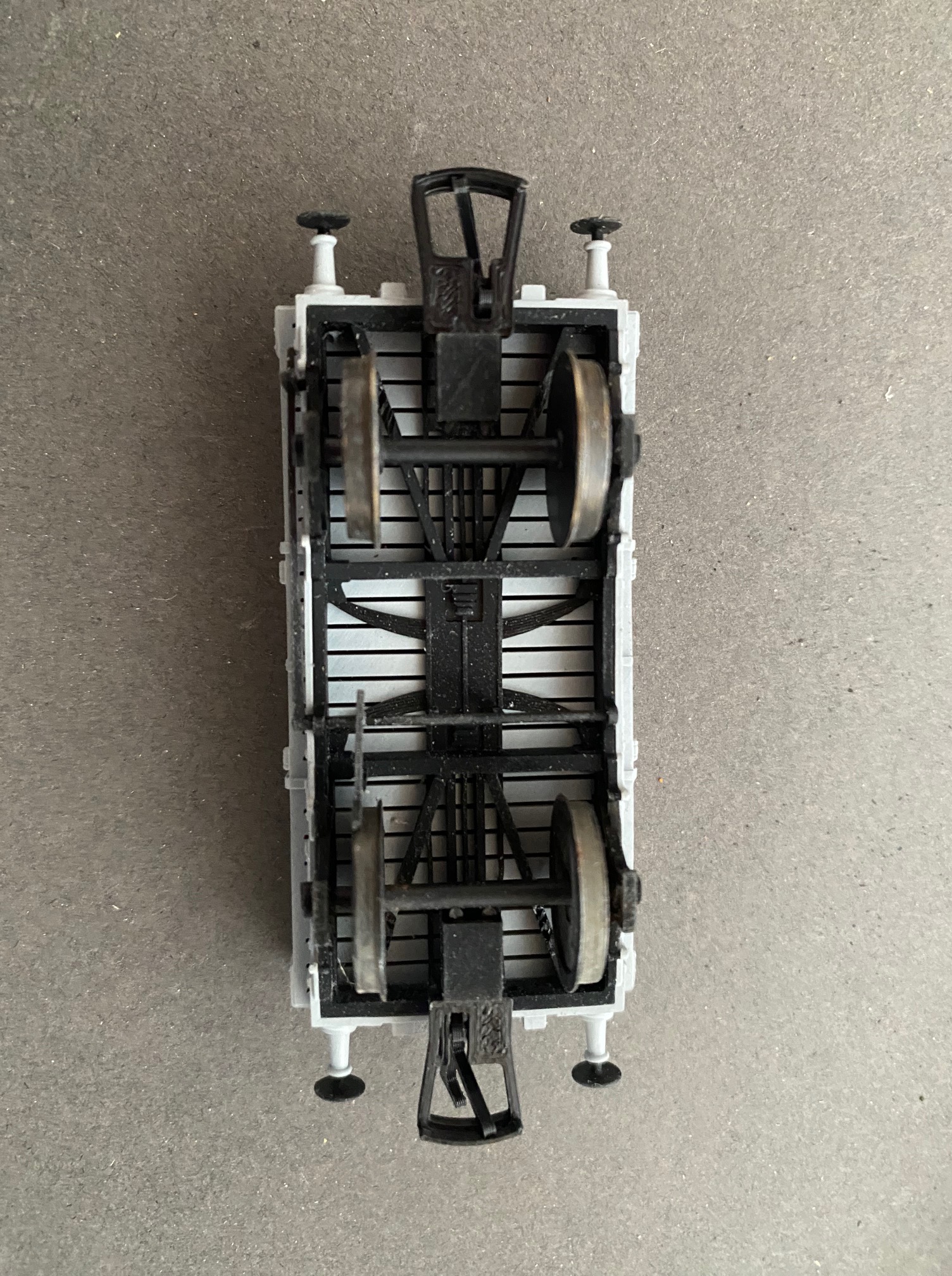
The principal dimensions of the model are generally good; except for one important point. Jones era wagons used 3’7” wheels and this is fitted with 3’2” wheels. One of the implications of this is that the buffer height is too low but fitting the correct sized wheels does correct this. Swapping the wheels as an OO modeller you will need a trim of the framing on the underside to allow the flanges clearance to turn and all 4mm modellers will find that the brake block fouls the wheels and has to be replaced – or as i did softened with the heat of a soldering iron and bent back. The correct wheels should be split spoke and whilst these are available from the r-t-r manufactures in the smaller size, I don’t think they do them in 3’7” so you Gibson wheels are your best bet. The impact of the larger wheels is quite striking; they look rather quaint and from a time past compared to what is generally available to the modeller – but then again, that is exactly what they are!
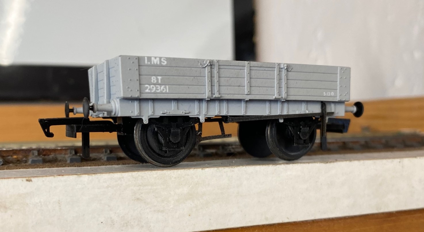
Most of the detailing is crisp and fine, but in some respects too fine such as the brake block. Conversely the body sides are too thick – possibly a compromise to make the model more durable or easier to produce – but never the less it makes the wagon a bit clunky. The buffers are separate and it looks quite realistic to convert them to sprung buffers if desired. The model comes with safety chains which are very nicely made but these would only have used early in the wagon’s life so the fixing holes need infilling for any modellers from the turn of the 19th century onwards. The trunnions also seem to be overly wide and the operating rod for the brake pivot has been extended to the blind side of the wagon for some reason – so a little surgery is thus required.
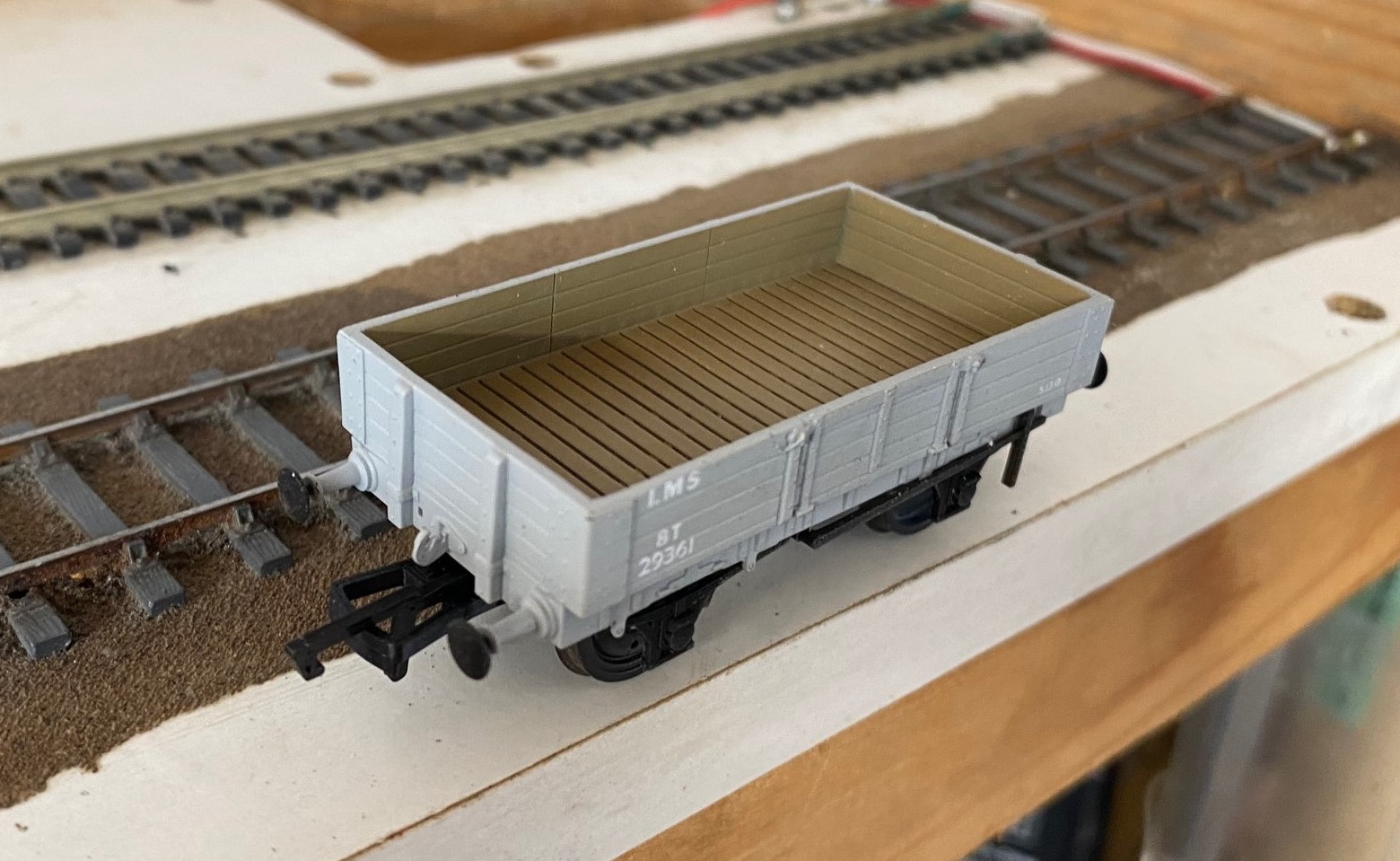
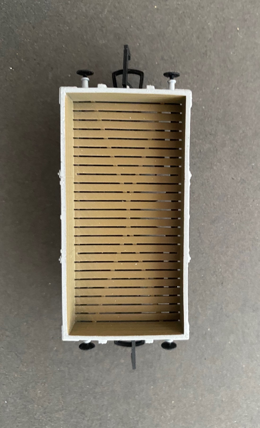
My model was bowed, with the high point to the middle of the wagon – whilst many wagons did bow over life, it would normally be the other way with a sag in the middle. This is likely to be a function of the manufacturing process – I suspect that putting it in very hot water will soften the resin and allow the bow to be corrected. What will not correct with hot water is the rather odd slatted floor – not sure where this comes from as there will have been no desire to deposit the commercial material on the track! A new plasticard floor is thus required. Less easy to fix will be the axlebox / springs which are significantly undernourished but are integral with the W irons so adjusting these will require the use of etched W irons and then castings if you can source these.
It is likely that this model is intended for customers who just want something “Highland” to go with their Jones Goods’ and for whom these errors are not going to be important. Against this criteria, the model is acceptable and if this promotes a bit more interest in the Highland Railway, this is fine with me.
However, if you want a more accurate model then the list of things to be attended to is not inconsiderable and as the joke goes, if i wanted to get to there, i wouldn’t be starting from here! I will be putting mine on ebay before too long is perhaps the most succinct conclusion I can offer!
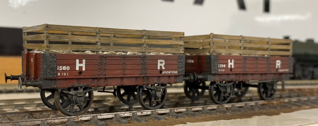
A pair of rather nicer dia 19 open wagons; this time fitted with raves for sheep traffic bult by Ian Terrell from Mircrorail kits. Whilst the origins of the kit will go back at least 40 years, they do look crisper than the Sams Trains version.

Delayed Delivery – Part 2
Once the basic structure of the gantry is in place, the real task of making the signals signally commences. First up were the smoke deflectors and the brackets for the balance weights. Also fitted are the main portions of the fan route indicator, but that will be explained further once I get it going!
For the arm bearing point and lamps I am using some 3D prints produced by Steve Hewitt and available from Shapeways. They can be found here https://www.shapeways.com/product/JJRSB … arketplace. They are fairly expensive but they are neat and save a lot of manufacture. There is, however, a but – they are very delicate and I am very fearful of thier long term durability. I am highly likely to draw some of my own up and get them cast in lost wax. It will make them even more expensive but I have about a 50% casualty rate at the moment, so maybe in the long term it will be cheaper!
The arms are Masokits, these are definitely the best available arms for LMS/LNER/BR semaphores. This is especially true of the minature shunt arms as the MSE ones are simply too delicate to bother with (imagine how do I know that………….!). So this is where we are now at with the arms mounted temporarly on the bearings.
There are five movements in the down direction (three of which operate via the route indicator) and then a pair in the up direction – hence the back to front arms.
The plates at the top of the dolls are mounting points for ladders. It transpires they are wrong and have already gone!
So the intensity level has dialled up a notch with these portions (especially breaking the bearing/lamp fittings) but it really gets interesting when you try and make these things work.
I don’t know myself yet (although I know for the couple of arms I have finished, so I have an inkling), but i think it might be fun to have a little sweepstake on how many moving parts there will be in the finished gantry. Five arms, three fan route indicators and each is operated by way of angle cranks. Each arm, crank and intermediate wire counts as a moving part, as do the servos………………..guesses please?

Delayed Delivery – part 1
After a long pause, caused by that irratating thing called life getting in the way, I am looking to deliver on some long made modelling promises over the holiday season.
The major task is a rather full on gantry signal with no less than eight movements on it (which is an improvement, when initially designed it had nine!), including a rather natty fan route indicator. This is for a friend’s layout and is in return for some signal cabins that he built no less than 15 years ago – I told you the promises were long made! Mind you, he hasn’t got the layout fully running yet, so I am still ahead of him!
The gantry spans only two lines so it can be formed with channel section. There are good drawings and pictures in LMS Journal no 5 of this. I have made mine from milled brass section and then the landing was a custom etch I designed as it takes a surprisingly large amount of material and effort to construct this from scratch. These etches included the doll base plates although the dolls have a thickened tube at the lower level which of course I forgot and had to undo later work to put on!!
The signal is to be located on an embankment which meant that I could not simply put flat base plates on the foot of the gantry columns. Instead I have constructed a housing that matches the slope of the embankment and then the baseplates are partially sloped to match this with square sections representing the foundations of the prototype columns. Below these baseplates I have then formed housings to take the servos which will eventually operate the arm actions.
So far, this is pretty easy modelling (although I lost a number of drill bits opening up the stanchion positions on the landing – grrrrrr!). The tough bit comes next……………
There are potentially two viewers of this thread who might be thinking that I have long outstanding modelling promises to them too……………I am also working on one of these too!!

News from Miscellany Models
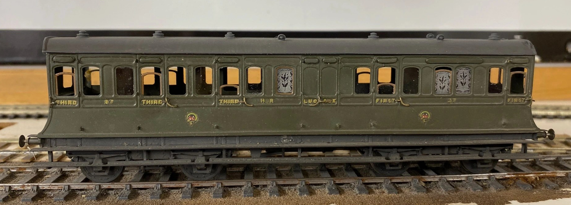
With the assistance of Duncan Petford, Miscellany Models are now offering engraved glass windows featuring the thistle emblem that the Highland used to obscure the windows of toilet compartments. They come in packs of five, for £7 postage included and are available here.
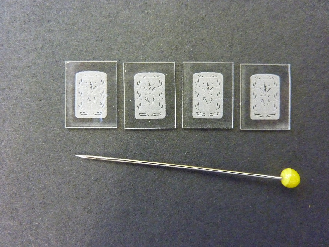
These are laser engraved on 1mm perspex and really lift the appearance of a Highland coach, as you can see:
Sadly, I have also had to increase the prices for most of the products. The costs of the last few deliveries from my etchers have been eyewateringly expensisve, so I need to defer a degree of this. The good news is that this is an indication that more products will soon be featured too – so Highland and LMS modellers keep an eye out.
A Dirty Skinhead……….the SLW Class 24
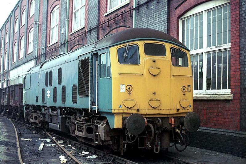
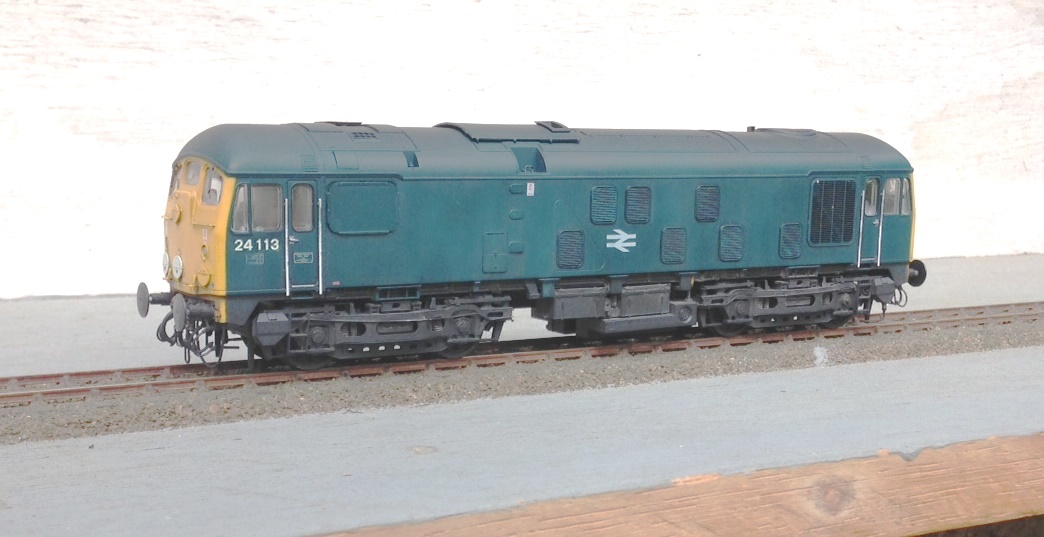
A skinhead; what’s he on? Well for the steam age people out there, a skinhead is the nickname for those BR built sulzer class 24s that did not have headcode boxes – as you can see below in Paul Winter’s photograph they did have a rather bald headed appearance and it is not difficult to see where the nickname came from.
Whilst the bulk of the class that ran on the ex Highland lines had the headcode box, for a long time one or two skinheads were allocated at Inverness and visited both the far north and Kyle lines. Given that they do look quite different I could hardly resist getting one to offer a bit of variety on the layout. I had been plotting getting one for a time, having bought the Bachmann version and even converted it to P4 but I had not quite got to enhancing or weathering it so it did not ever make it out onto the layout.
There are failings in the Bachmann model that have annimated many; the worse being the slope of the cab front which is too steep. Whilst I feel it is close to invisible when the Bachmann model is used as a doner for conversion to a headcode fitted version (see my article in the Highland Railway Journal, issues 96 & 97) it is more apparent without the headcodes, simply because they act as a bit of a counterpose to the slope. This was one of the reasons that my skinhead was languishing in its box (although, doing other things was the real reason!). Although I am aware that a recast of the model has been in the offing for a while I did not know that a new manufacturer, Sutton Locomotive Works, was in the process of producing one until it simply appeared at the turn of the year.
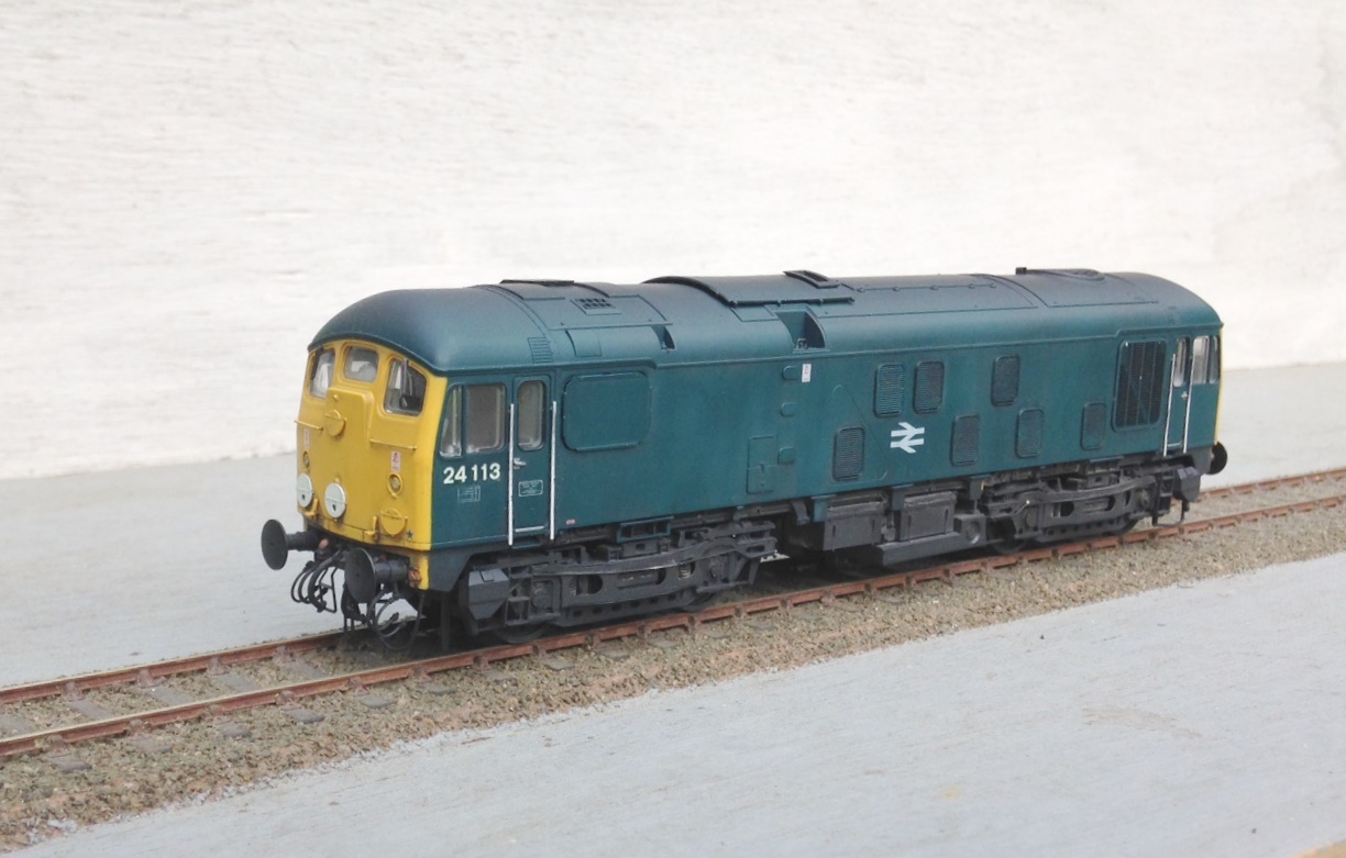
It is fair to say I was a little sceptical initially, partly due to the pretty punchy cost of the model but also due to the amount of airwaves noise it was eliciting. However, they were at one of the shows that Portchullin was at and of course I went over to have a gander………. What I found was that it was really a cut above the Bachmann version, both in terms of correcting the cab and also with the quality of detailing but more than that, it had an onboard sound system that was significantly better too (and tellingly, more controllable). An added bonus is that the model can be supplied, at a small additional cost, with your choice of EM and P4 wheels, thus making it the first true ready to run P4 loco.
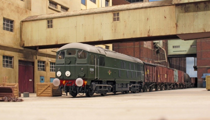
Initially the model was available as one of the first batch in a “just built” form in green and as 24 081 in blue, as it now is in preservation. A bit of hunting about prototype information – notably Derby Sulzers – showed me that no’s 5113 & 5114 were transferred to Inverness for the last couple of years of their life (which coincide’s with Portchullin’s era) and that these were pretty close in form to the 24 081 form of the model. That decided it; off went a cheque and back came the model – in a spectacularly substantial amount of box and glinting clean like a museum piece!
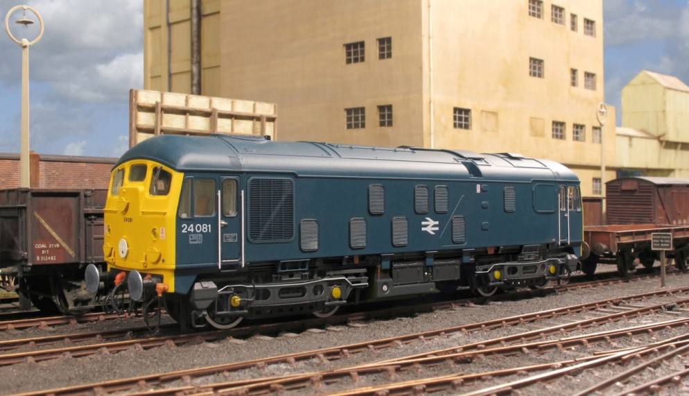
A look over the model proved to me that it was really very good, but not perfect. The worst problem, by far, is the glazing that suffers from the moulding lines no less severely than Bachmann/Hornby models – apparently, short of putting in individual pieces of glazing, this problem is insurmountable. Good news for Shawplan and their glass replacement kits – if Brian is not going to do a set for this model (are you Brian?). It will repay doing them by hand no matter how hard this is if Shawplan don’t do them. The other problem was a lot less than crisp junction between the yellow ends and the blue sides – most visible in the fianl photograph. I did make this a little better with some 1200 grade wet & dry, but it is still not all that I would wish it to be.
It is fair to say that the good bits are very good indeed. It runs perfectly (although some others have muttered about theirs) and all of the detail is very delicate – compare the door grabrails with the other models or prototype for example. I understand that the number of seperately applied parts is exceptionally high and I can beleive that, it really does look quite a lot better than the alternatives even after the “supe-ing up” that I gave the two headcode box fitted versions I have. There are a lot of detail variations between the vehicles and care is needed to chose wisely if you have a specific example in mind – time for a good book!
Sutton Locomotive Works approach is to release relatively short runs of differing varients, their second and third batch has already been released (see their website). They are not saying, but I suspect some Highland Sulzers will be inevitable before too long – I am saving up anyway!
But the model is way too clean; although Inverness did not allow their locos to get too decrepit looking and they clearly saw the inside of the washer plant pretty regularly, they did take on a careworn appearance especially given that they were knocling on 20 years old by the time I am modeling them. So, some subtle weathering was required – do I have the subtly of skill to do this – not really was my conclusion, not on my own anyway! So some help was enlisted from OTMC who I share occassional modelling days with and yesterday we had a weathering day instead.
Prior to starting the weathering, the number was removed with 1200 grade wet and dry and replaced with Fox transfers, protected by some brushed on matt varnish. The dirty-ing of the model then started with the creation of some “gunk” – a mix darkish grey with a tad of brown mix – Tamiya acrylics. Whilst this was a relatively thick mix, it was brush painted over the more extreme coloured sections of the model – the lifting points, axle boxes and coloured pipework to the bogie and drawbar. Then the gunk was diluted to a wash and sprayed onto the model; heavily on the underframe/bogies and more lightly on the body side. An acrylic solvent was used and this evaporated almost immediately and once the paint was on, efforts were taken to remove it from the sides. Cotten buds and make up buds (similar but with a flat head) dipped in acrylic thinners were dragged downwards on the sides and ends. This removes the majority of the paint, leaving only that which gets into the nocks and crannies and can not readily be reached by the buds. If the paint gets a bit stubborn (which it did, especially on the ends) then the process is repeated using enamel thinners which is much more vigerous and takes the acrylic off almost immediately but acheives the same effect.
 #
#
I did encounter a couple of problems. The first was not of my making in that it proved very difficult getting the wash out from behind the grab handles to the front of the cab – eventually this was fixed with the use of cocktail sticks. The second was firmly of my making in that I used some meths to clean of some grease stains from my fingers right at the end. It would appear that meths is pretty effecitive at removing both the wash and also lightening significantly the original blue paint on the model – aghhhhh! Ultimately, I have had to repeat the wash effect a couple of times on the side that I did this on and it does not look nearly as subtle as it did before – so do as I say, not as I do!!!
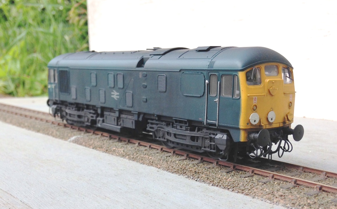
The wash was then darkened a bit and used on the roof. Initially this applied without masking to the centre and then subsequently with some masking. The masking was applied such that the edge of the tape was at the line of the roof with the cab front yellow and pressed home. However, along the sides the tape projected 5mm above the cant rail but not pressed home (so it sort of flaps above the edge of the roof). This gives a soft boundary between where the spray goes and the protected surface below and neatly mimics the effect of the washing brushes failing to reach the roof as it slopes away.
The grilles were picked out with a black wash effect that has a touch of gloss in it. The same was then used at the axleboxes and around the fuel filler points to mimic spilt fuel oil. The while of the underframe and boigie then had stone colour mig powders dabbed on them. As with the wash, once it is on, take it off with a brush – in this case it tends to attach itself to those parts that the brush presses it home on. So it tends to catch more the projections than the recesses and neatly highlights the detail on the underframe/bogies. Not done yet, but I will apply some break dust powders around the brake blocks and wheels to finish the full effect.
Portchullin’s next outing will be down in the west country – 30 July 2016 in Barnstaple. Come and see the new engine – hopefully it looks a bit like this?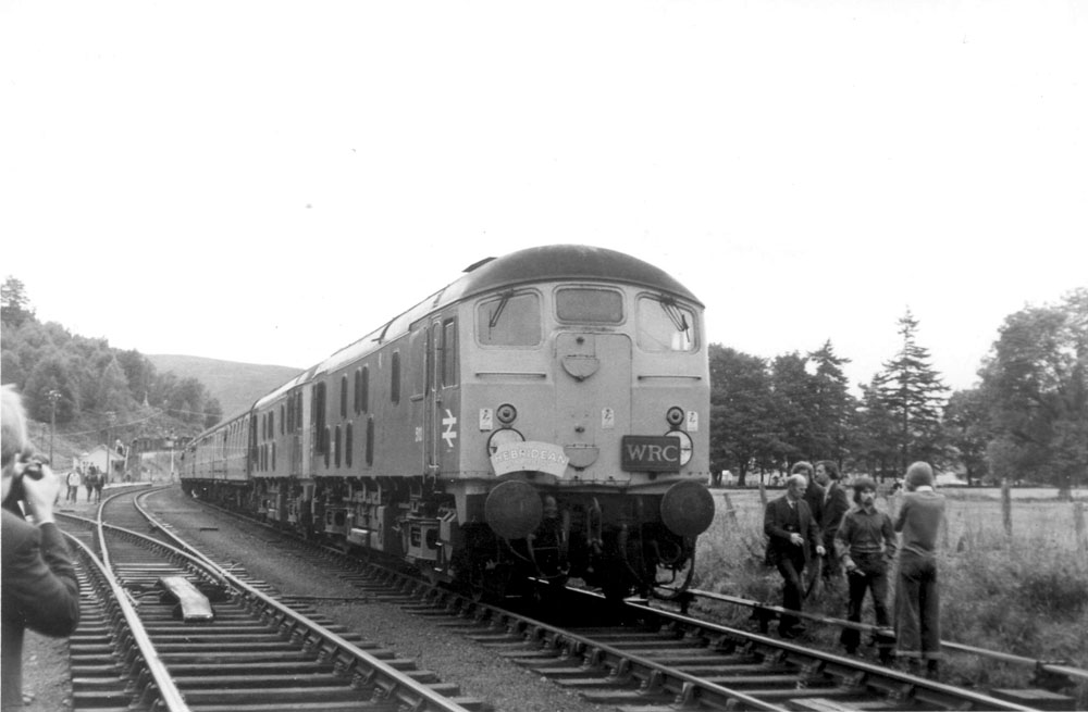 ry
ry
In the light of all the excitement that tresspassing to see the Flying Scotsman is presently giving Network Rail, I wonder what they might have made of this – and then there are the flairs to consider…………. Chris Longley, is that you – I know you were on this particular tour!

New Shoes for Some Old Friends
Over the last few weeks, I have been revisiting a number of model coaches that I have built in the past, typically quite some time in the past as most of these have been around since either my teens or twentys!
Over the years techniques have changed and I undoubtedly would not build most of them in the manner that I originally built them if I was confronted with doing them again. Having said this, on the whole my handiwork – especially in respect of the painting and lining was really quite good. I seem to have lost my lining mojo in particular, so I am not sure I could line as well as this now. This is something that I really must get to grips with this, as I still have a lot to do!
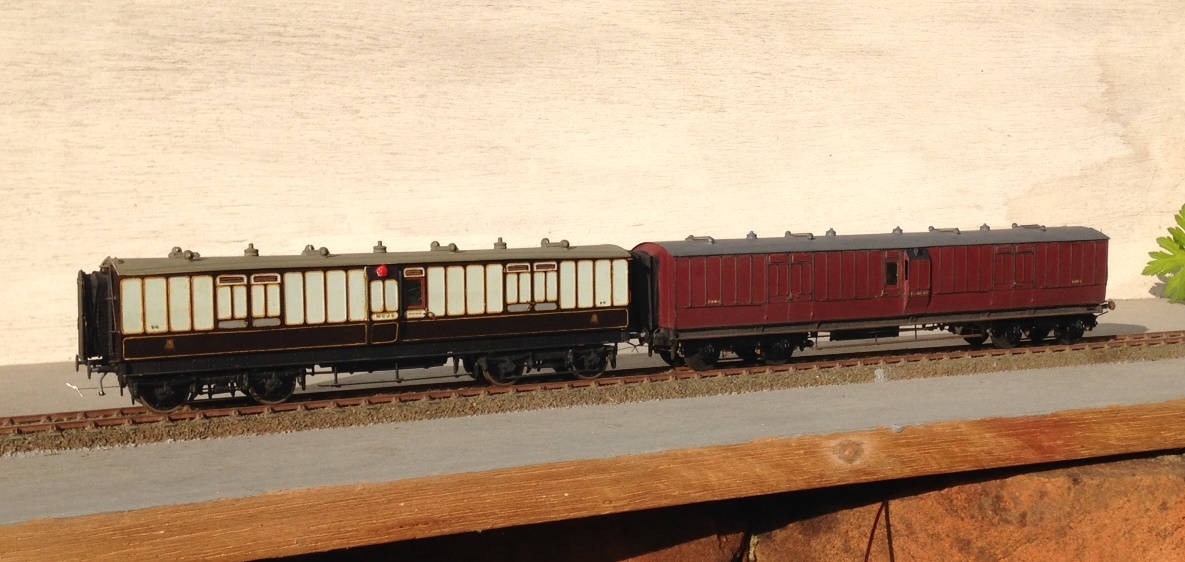
a pair of full brakes, the one to the left is a West Coast Joint Stock (from a London Road Models kit) and that to the right is straight LNWR (from a Microrail kit)
But the biggest area of difficulty with the coaches is that the bogies were generally formed around beam compensation units. These are OK for a couple of coaches behind a branch train but they impart far too much friction for a full main-line train as I aspire too. This is impossible to overcome whilst retaining the compensation units, the bar is the cause of the problem and it has to go!
To overcome this, Bill Bedford sprung boiges are being retro-fitting to all of my existing stock. These rely on separate hornblocks that secure a pin-point bearing in them – so rolling resistance is significantly reduced. The hornblocks are held in place by way of guitar wire and the effect is that they glide around the trackwork. They thus give the impression of weight and inertia that is much better than compensation (it is possible to get compensation that does not use the rocking beams that are the cause of the fritchion I am complaining about).
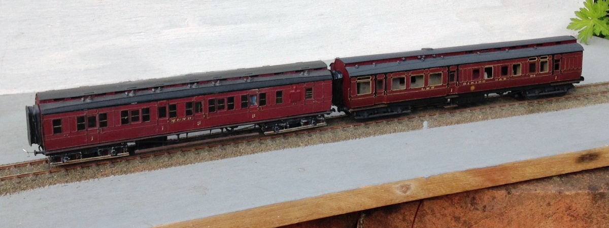
A Midland & North British luggage composite (from a PC Models kit) and a LMS (ex Midland) dining car (from a 5522 Models kit).
The Bill Bedford units are only an inner bogie and they still need to have some form of detailing on the outside. Some of these have entirely cosmetic outers, either of plastic or white metal but the two Midland coaches and the Highland TPO have something slightly different. On these, I utilised the original etched bogie sides and laminated them onto the Bill Bedford inners. This is very successful as it improves the Bill Bedfords notably by making them a lot stiffer and you get the crispness of the etching process.
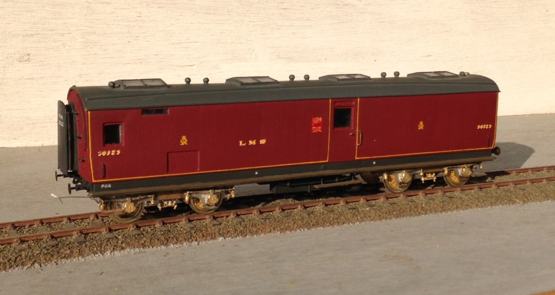
This is one of my fathers, so I can’t claim credit for anything but the bogies. A Highland Railway TP (fully scratchbuilt). Obviously, no painting has as yet been done, so it does rather look like a ganster with gold teeth!
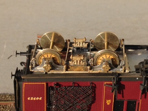
It is rather challenging to see how the Bed Bedford sprining unit sites inside the outer skins (from a Lochgorm kit) – so I will write up the process in a future blog – but this is what it looks like from the outside.
If, by the way you fancy some Fox Pressed Steel bogies that are neatly sprung and look the part – and almost all pre-group modellers ought to – keep watching the space. Subject to a test build or two, there will shortly be one available on the market.
To test them, I took them and a few other coaches to ExpoEM to use their test track. Here we see a Barney with eight on – albeit a rather od mix for the train and there is a fair amount of painting and lining still to be done.
And to prove that they really do work and also to allow you to see how they glide, a quick youtube video: https://www.youtube.com/watch?v=6D7a_cWwGhg&feature=youtu.be

The Far North Line
In my last visit to the Highlands, I took my father up to almost the extremity or our island to Thurso. The purpose of doing so was to mooch around portions of the Highland Railway north of Dingwall but also to drop in on Richard Doake. Richard is a fellow follower of the Highland Railway and has a rather nice layout depicting a pair of the Far North line’s more interesting stations; Helmsdale and Thurso.
Although Richard has sought to use a large degree of ready to run stock, most of the infrastructure on his model has been scrachbuilt so that it captures the Highland flavour. This includes signal boxes, goods sheds, water tanks and the like – the combined effect works as this is one of the most authentic feeling Highland layouts I have seen.
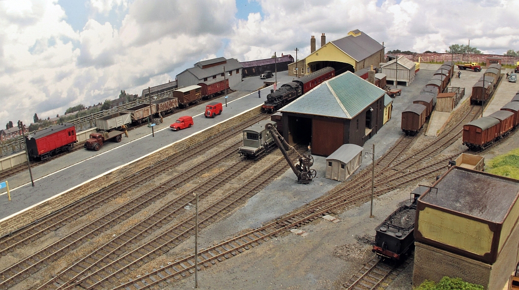
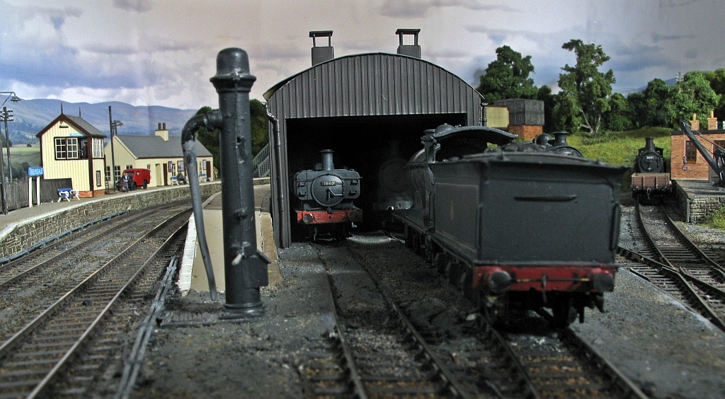
An overall view of the main part of Thurso.
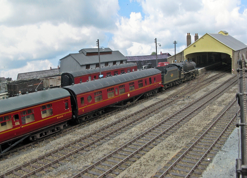
The train shed is a reduced liength version of the real thing (which is still there for those that don’t know). This view would have been a daily occurance in the late 1950s as a hiker concludes its long journey from Inverness with the Thurso portion of a Far North train.
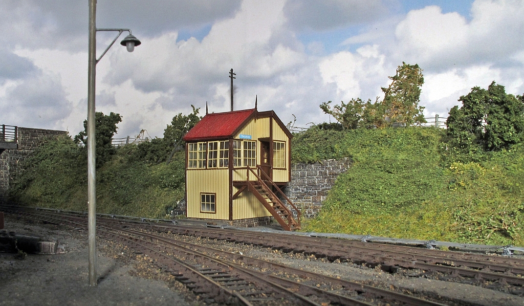
The signal cabin at the station throat.
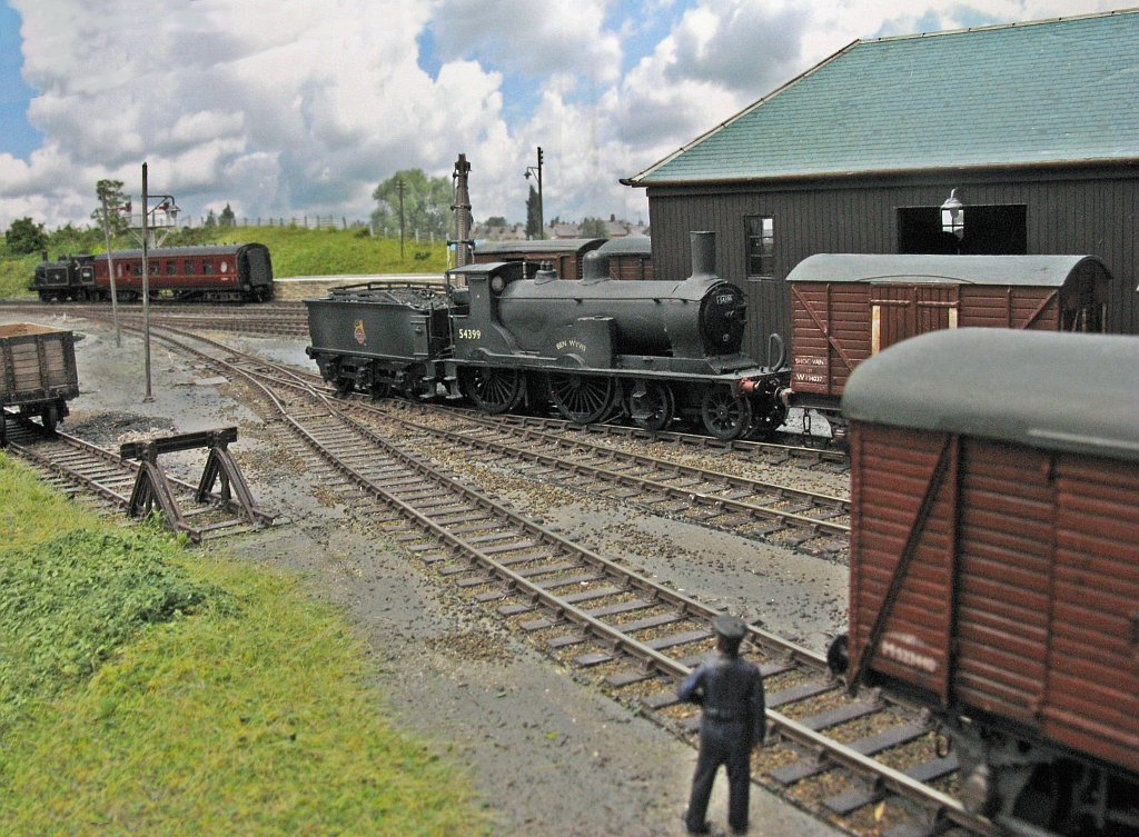
A small ben, Ben Wyvis, does some shunting in Thurso’s yard. This has been converted from a Hornby T9 with a replacement tender. The wheels are in reality 6 inchs to big and the boiler is consequently too high, but I bet the Highland fans that read this didn’t notice until I told you?
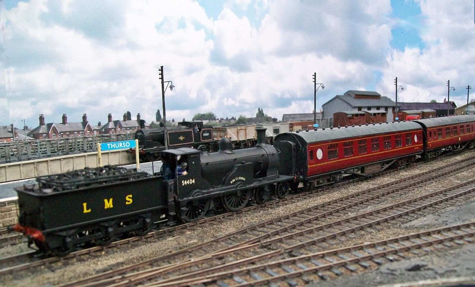
Brn Wyvis’ sister, Ben Clebrig acting as station pilot at Thurso.
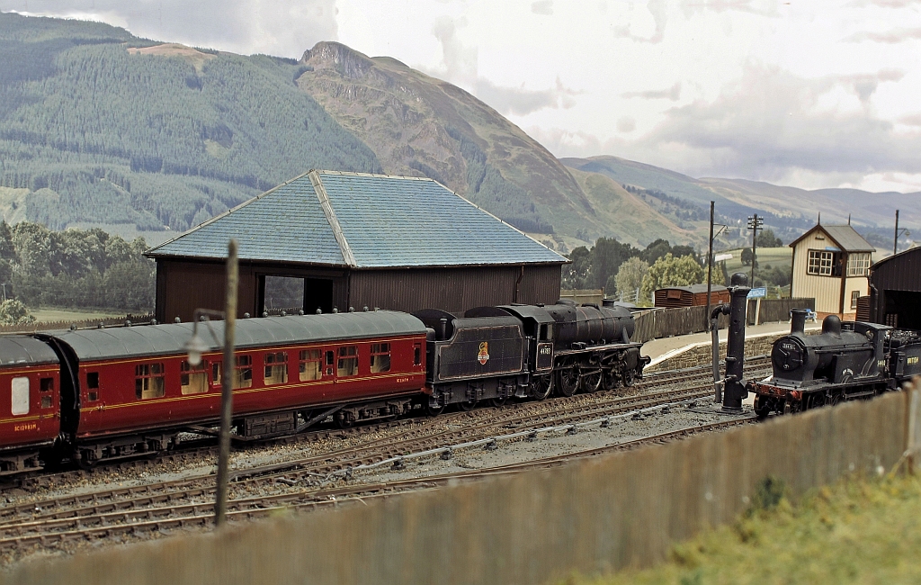
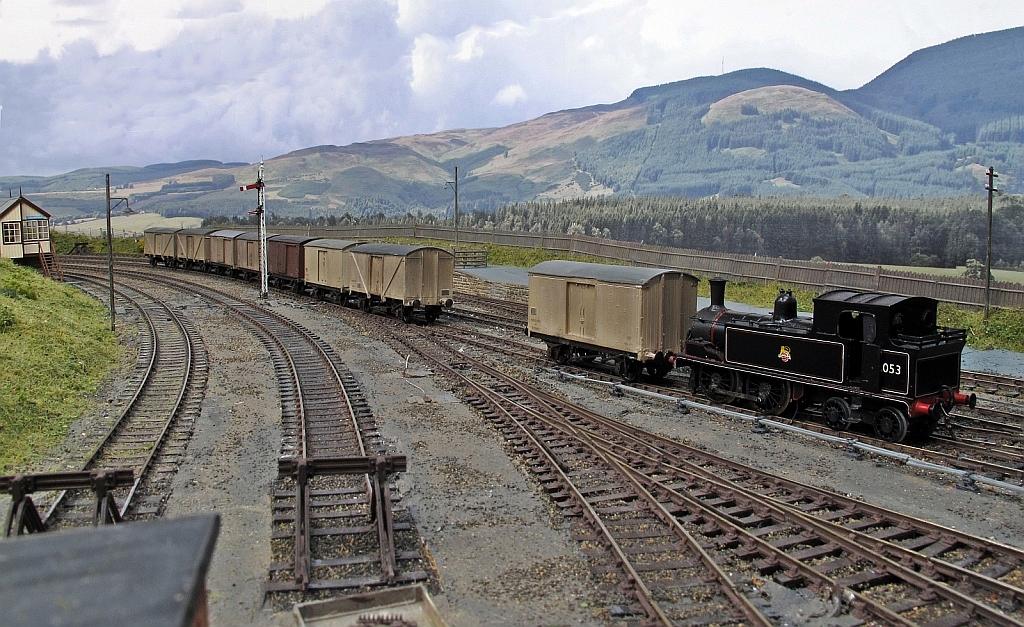
The other station is Helmsdale and here we have the Hiker once again returning south. passing a typical Highland goods shed.
A Pickersgill on shed at Helmsdale, along with a pannier. A pair of panniers were regularly found at Helmsdale in 1962 as they worked the Dornoch branch at this time following the failure of the last operational Highland locomotives, some small tanks.
And here is an example of this tank – aptly named Passenger tanks as they specialised on lightly loaded trains on the short branchlines the Highland had a number of in their region.
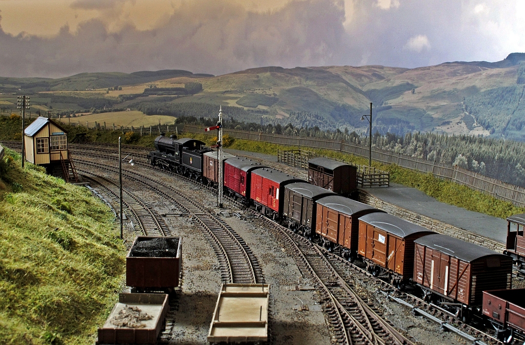
Like on the Kyle line, van traffic was a big feature of the line and here we see a clan pull out northwards with a train of vans and non-passenger stock. The eagle eyed will notice that the clan is in BR livery where in reality they did not last long enough to carry this. Richard is quire relaxed about this as it enables him to include locos he fancies!
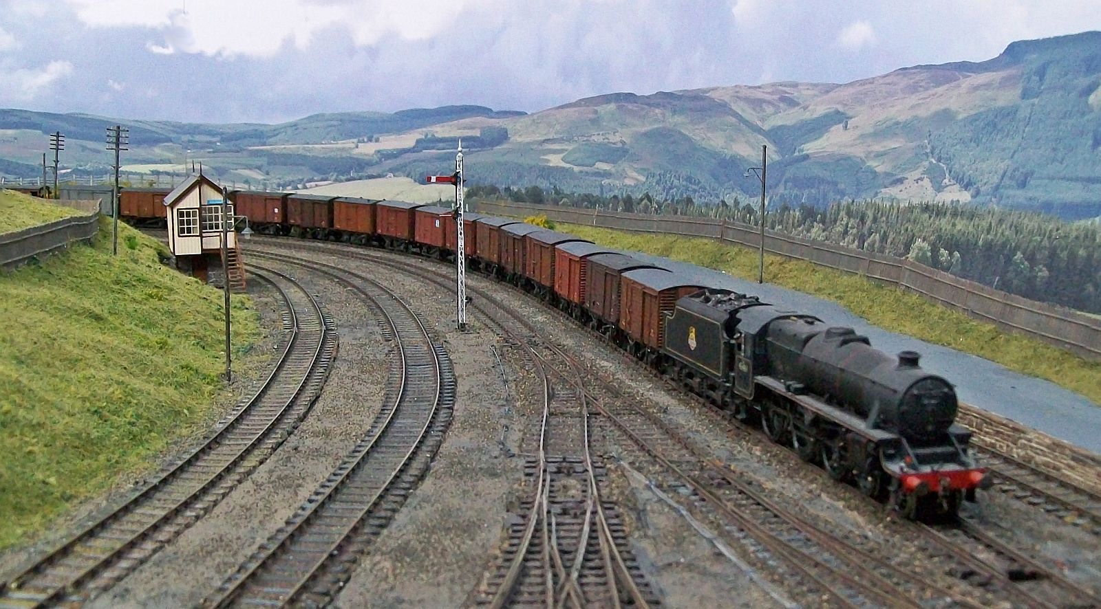
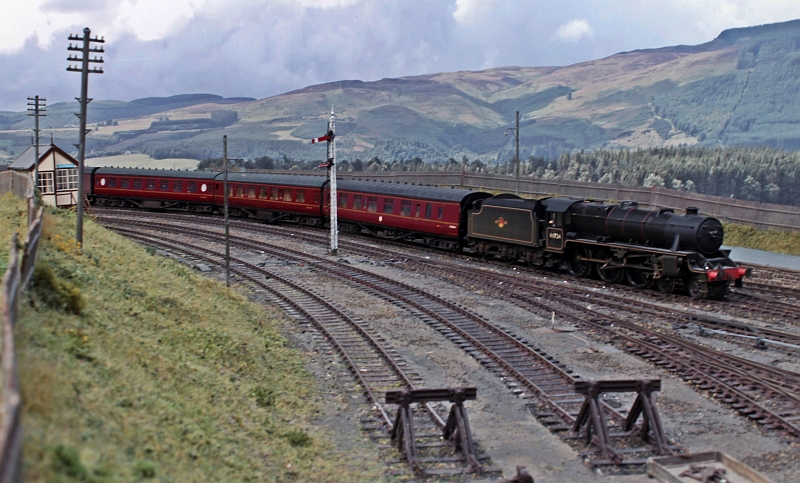
And a similar working heading south with the almost enivitable (for the real thing) black 5.
So thank you Richard for entertaining us and also for the use of your photographs – rather better than my own!
Glenmutckin Shed Area
Glenmutchkin’s shed area is modelled on Kyle of Lochalsh’s (it is a mirror image) and I wanted to capture the typically cramped feel of the inspiration. This is the original OS map for the shed (ie old enough to be outside of copyright).
Key to this is the way that the whole complex centres around the turntable and the first turnout is almost tight against the turntable’s wall as this photo extract shows (notice there is not even a buffer stop on the far side of the well):
The first turnout is, you will see, a tandom and whilst it is not visible in this picture, almost certainly it was interlaced (as the Highland always seemed to always use interlaced turnouts). Well, interlacing gets quite crowded on a tandom turnout, as you can see:
It takes a long time to do all of the sleepers as there are a lot of them but once it is done, it does look rather impressive don’t you think?
_________________
Mark Tatlow

Aultbea Revisit
A year ago, I posted a few photographs of one of my friend’s layouts, Aultbea.
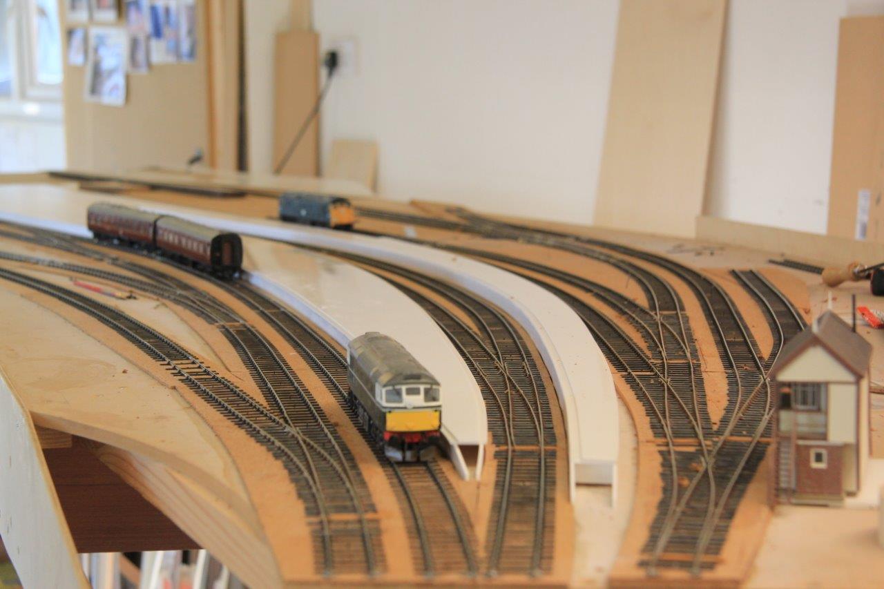
Peter has been making progress with the layout and now has the bulk of the trackwork laid, so it is worth having another look at it:
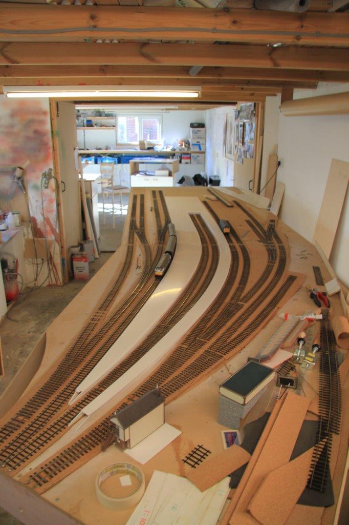
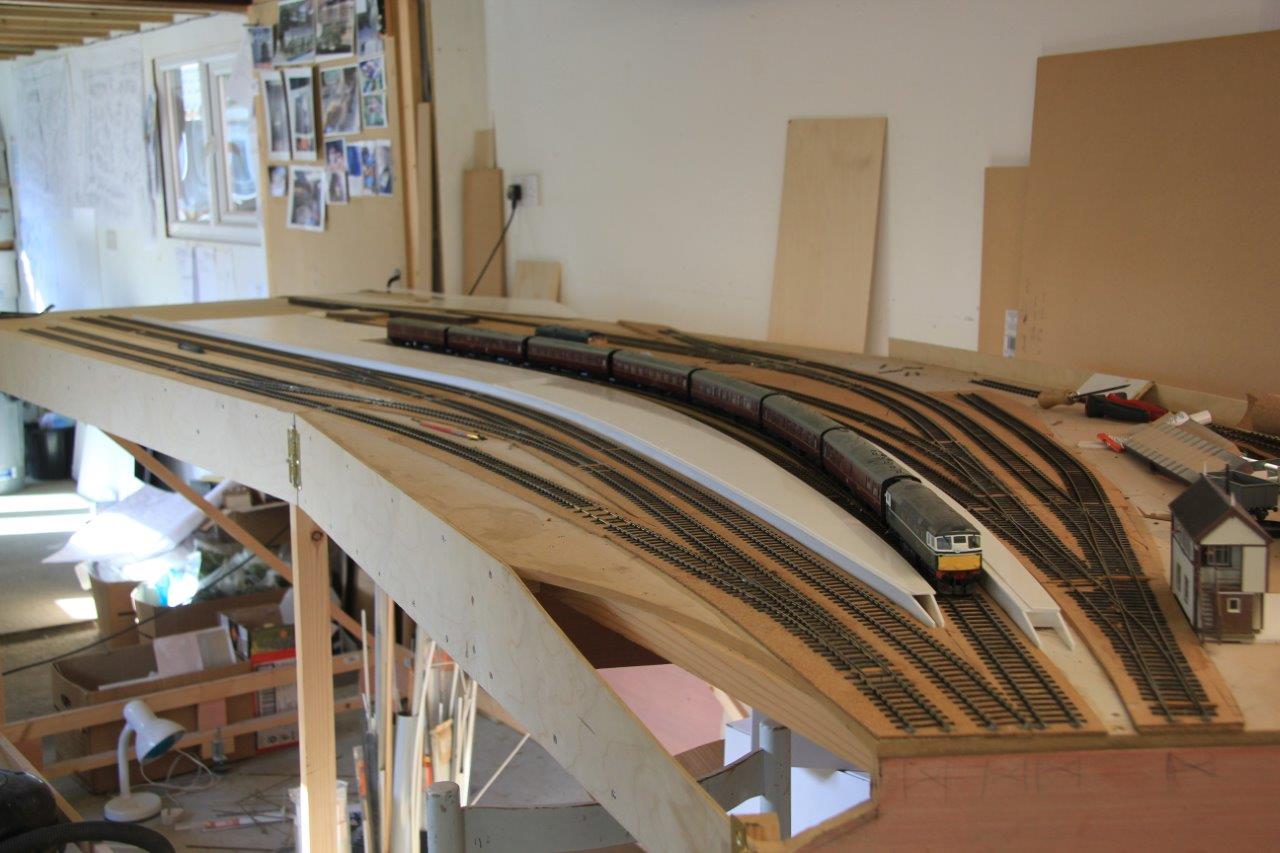
As you can see, it is a bit of a beast because this is only the passenger station complex, the MPD and sidings for the military are not even on show here!
The full extent of the layout can be seen in the previous posting and you will see he that even the bay is conceived for a seven coach train. Looks like Peter will need to be building/converting and otherwise acquiring a fair amount of stock!
in the views you will see that a some of the buildings have been finished – the signal cabin and the water tower. I think station buildings are next and before too long, he will mention signals I suspect!

Boards Back Home
Just prior to Portchullin’s last two exhibitions, Tim of S&T Joinery brought around the last couple of boards so that all of the scenic boards are now back at home. Obviously, this meant that we had to do a test erection!
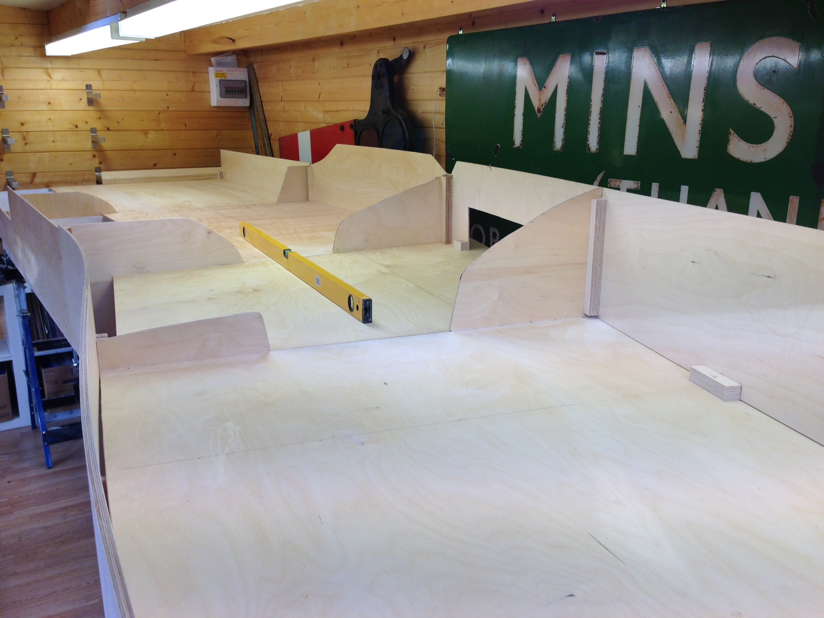
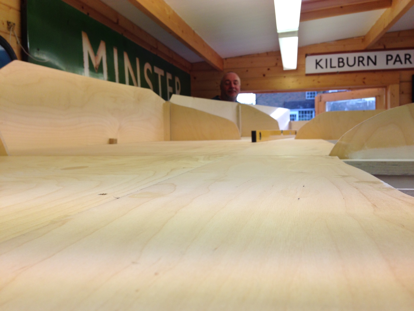
And very pleased I am too, especially with how flat they are. A rear contrast to the rolling hills affect that I managed on Portchullin. I am obviously hoping that this is going to result in much better and more reliable running.
The design of the leg and the supporting beams can now be seen more clearly. it does take a bit of time to get these level (caused I believe by the absence of levelness in S&T’s workshops! However, once the beams were level, it was a matter of moments to place the boards on them and connect them up. So I think we will do some setting out at the weekend.
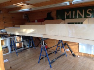
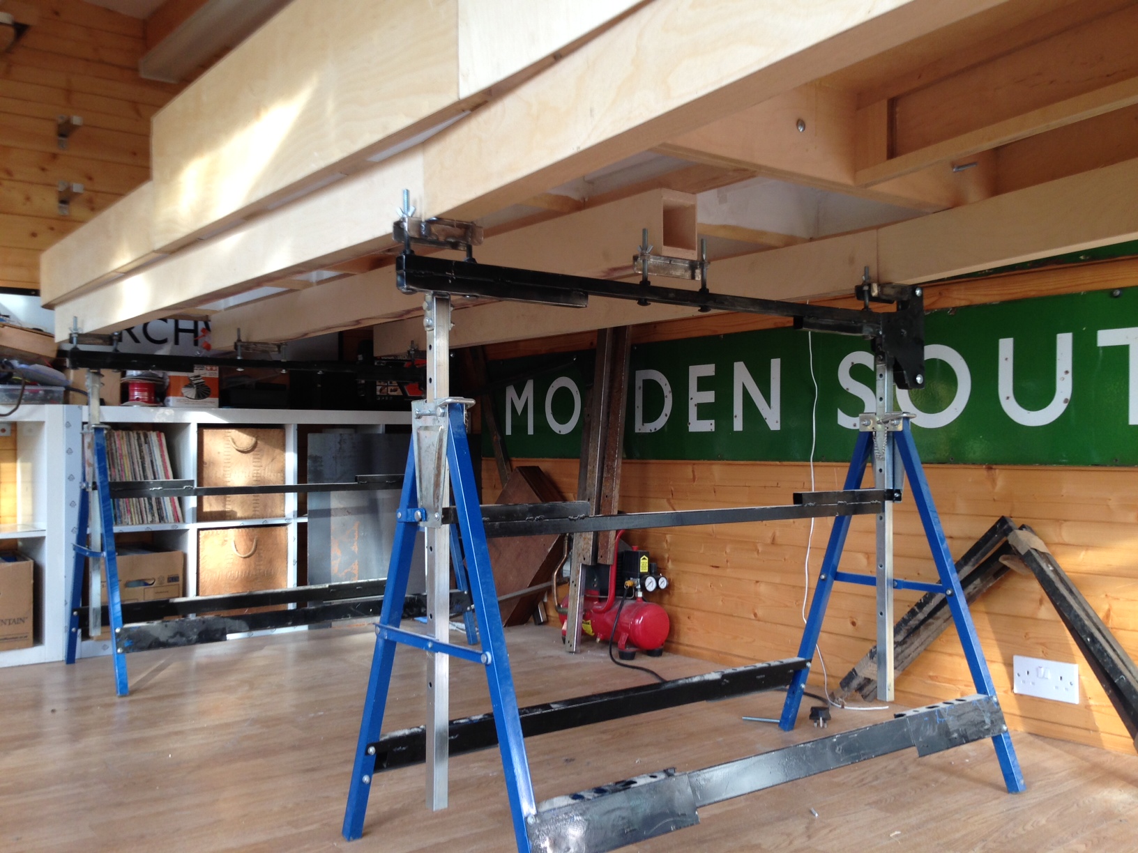
In some respects the photos don’t quite do justice to these boards and also how large they are collectively. The width in the top view is 1200mm and overall the length of the boards together is 5250mm. As will become apparent in future posts, I am going for the “railway in the landscape” feel and I don’t want it to fee cramped either.
And if anybody wants an electric loft ladder, this is where you go http://www.st-joinery.co.uk/
