Blog Archives

What Have I Been Doing…………..?
Gosh, another year where my intentions to increase my rate of posting have got away………..
Whilst work and home life have intruded, I have still managed to get some modelling done; including a rake of NER coaches for John James for which i do get something in return in due course.
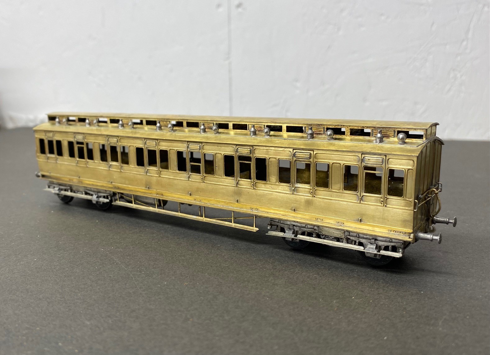
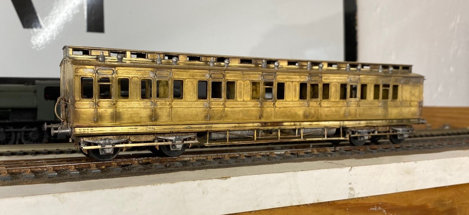
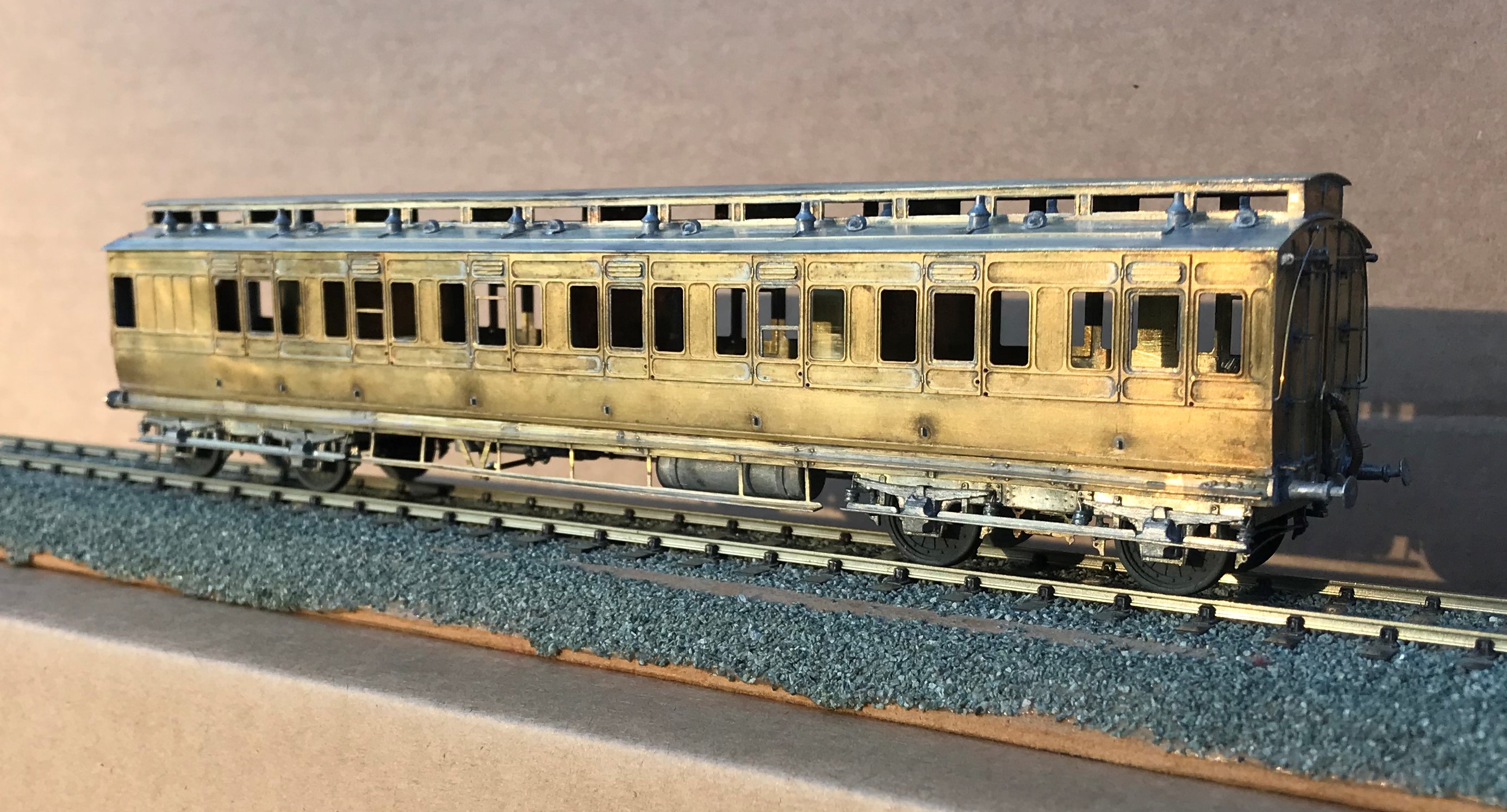
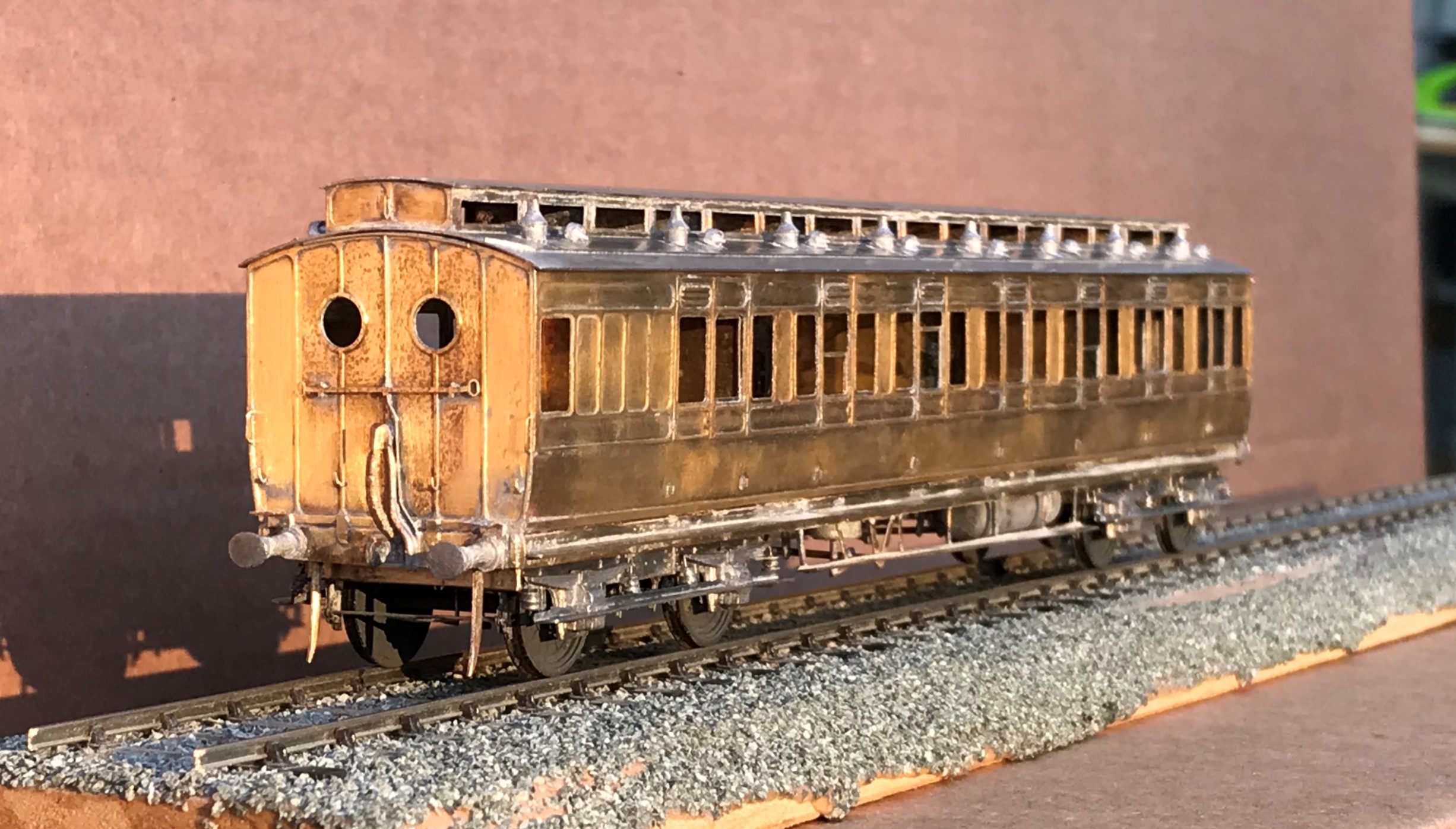
The rake had a pair of three compartment thirds, of which this is an example:
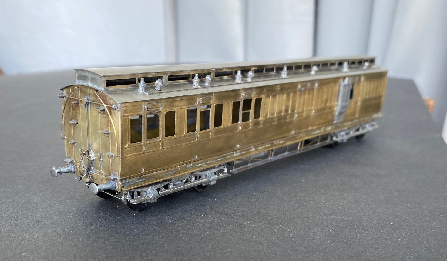
All of the coaches were constructed from D&S kits on my Miscellany Models Fox bogies with replacement roofs formed of nickle silver sheet. I find that the plasticard offering in the D&S kits to be their weakest point. The problem with this is that if you make your own roofs i find you might as well also cut out the section below the clerestory – it makes a huge difference for the coach to be illuminated from above. The issue is, that there is a lot of work in these roofs – I found that for each there was 15+ hours of work just in the roof!
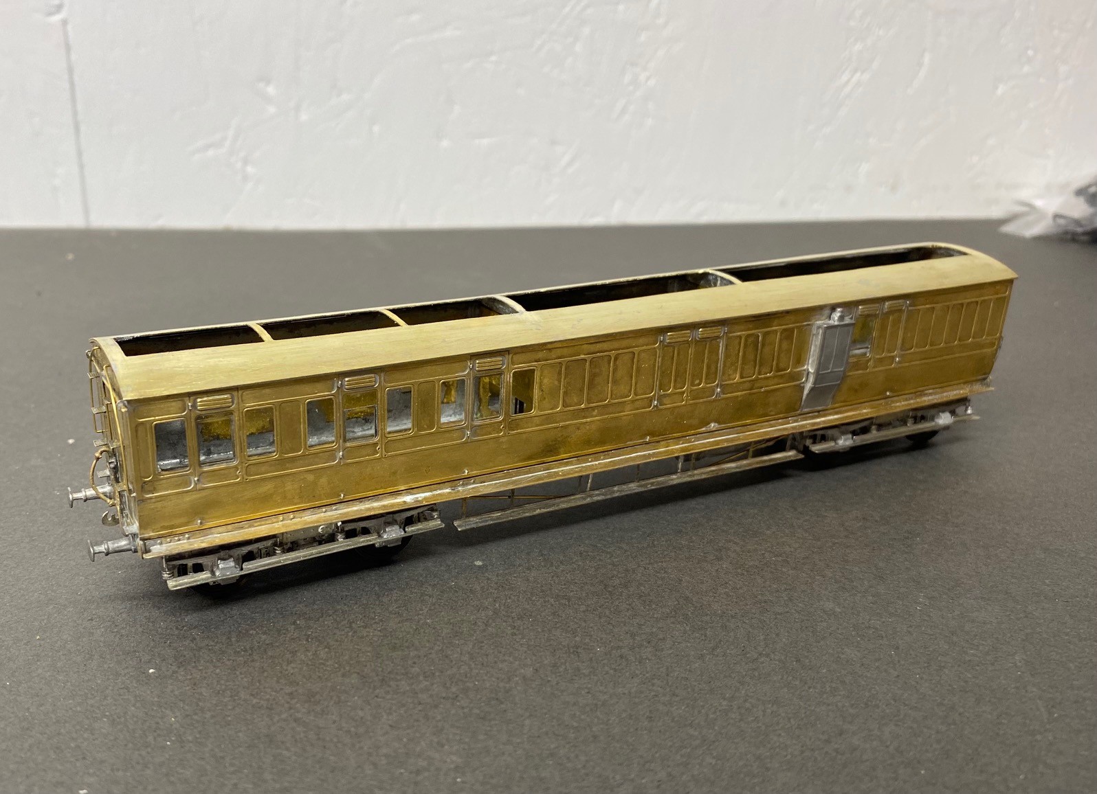
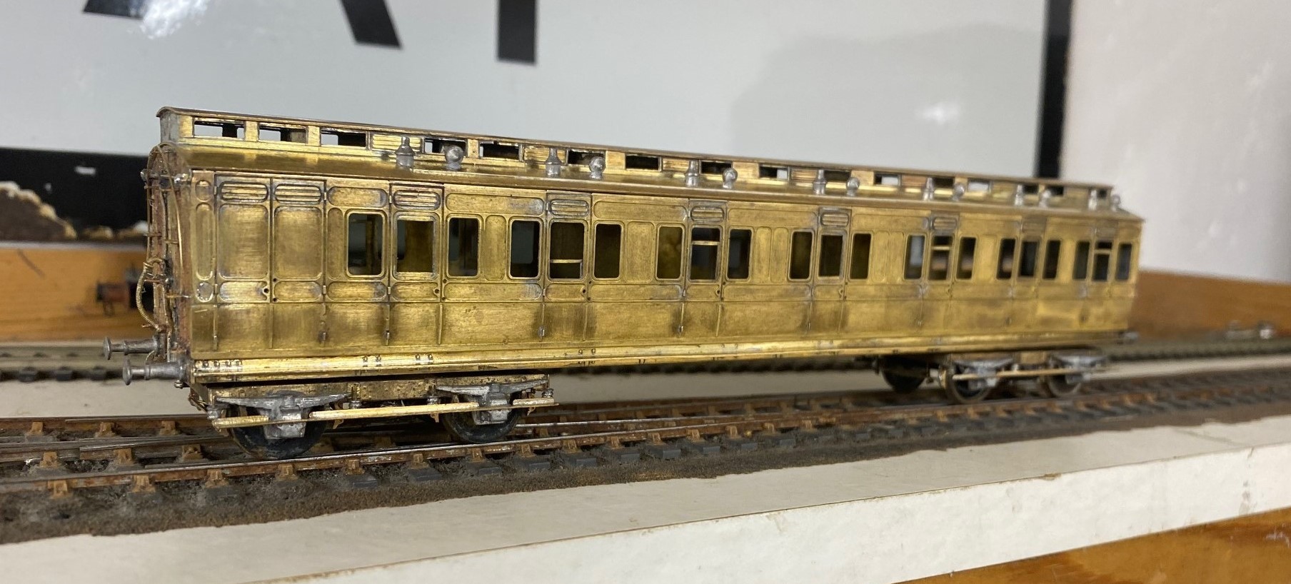
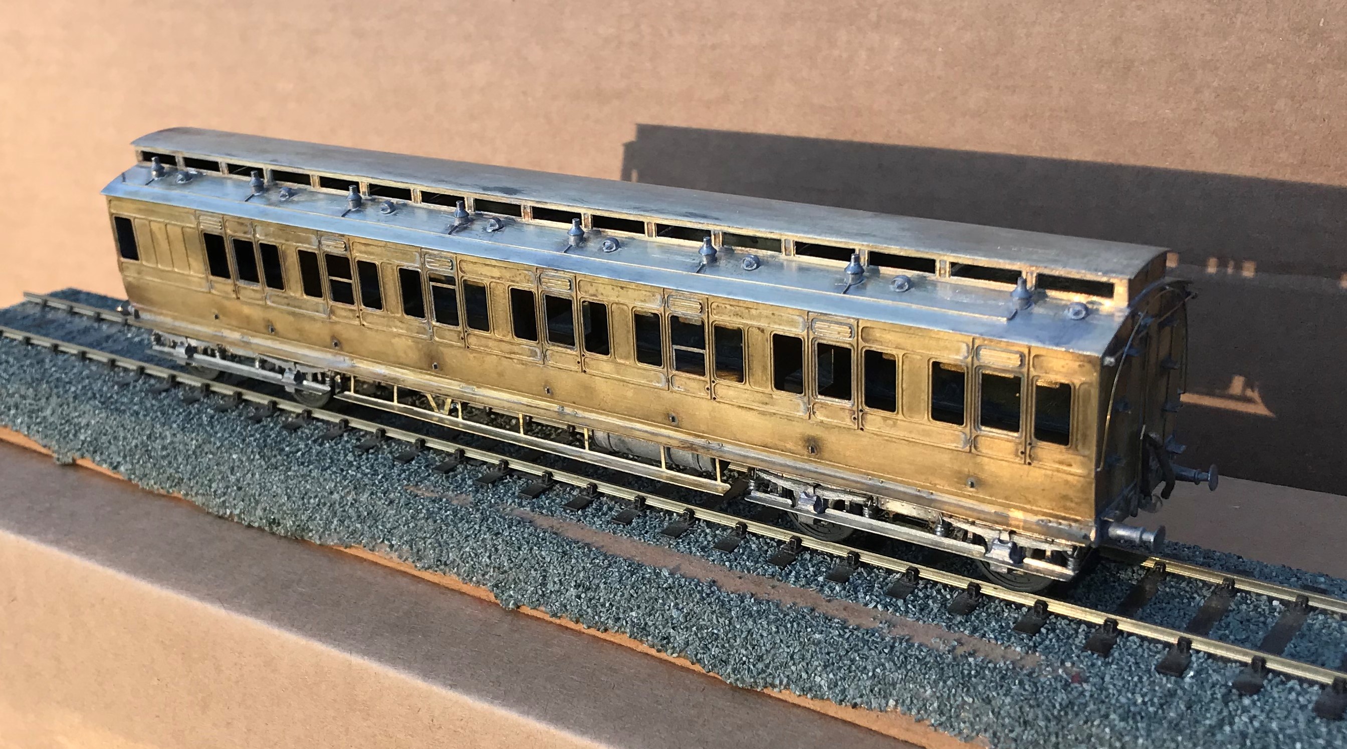
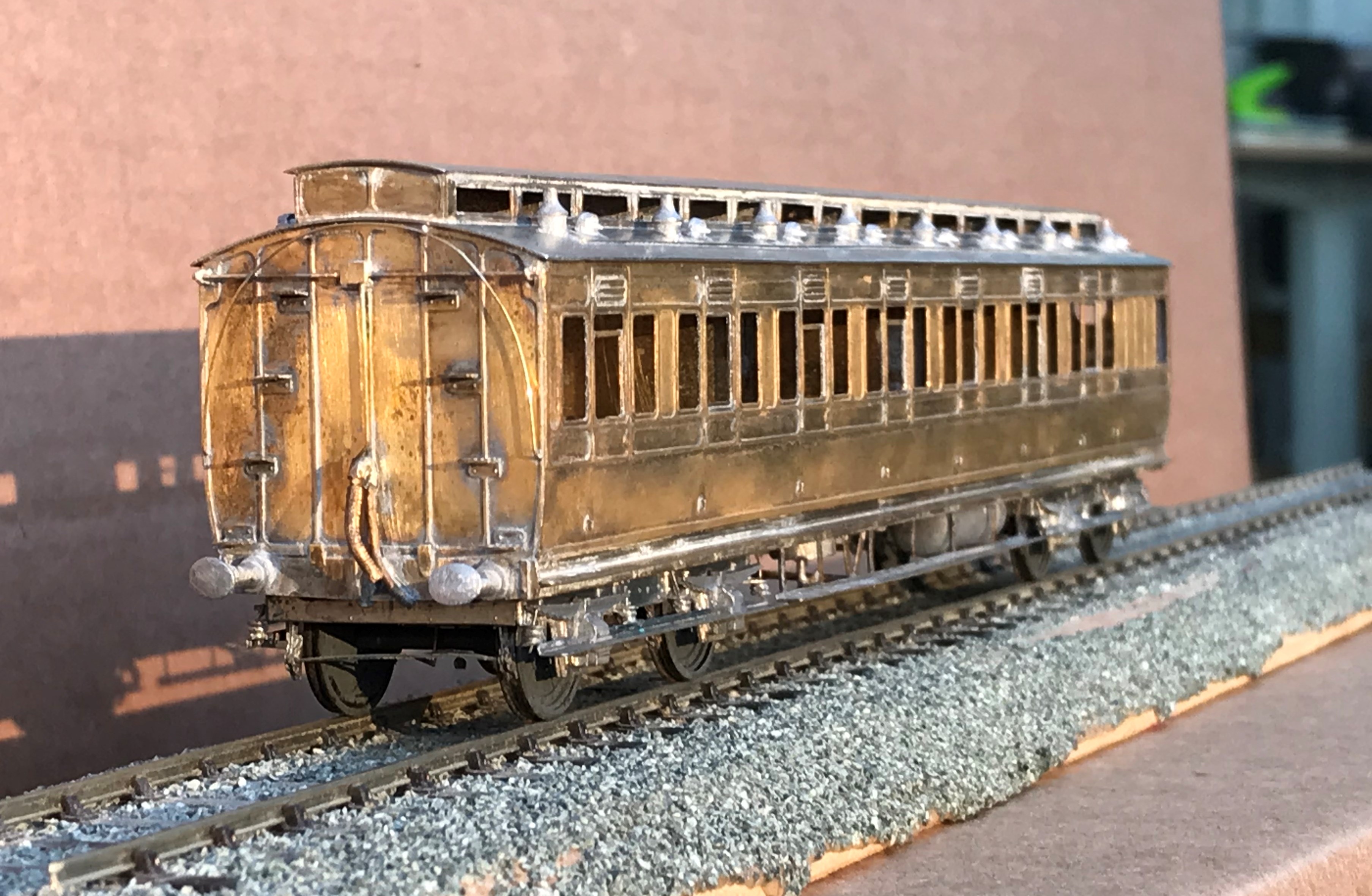
Also in the rake is an all third, which is probably my favourite of the build as it feels quite “pure” and also wihtout the problems of the composite…….see below…….
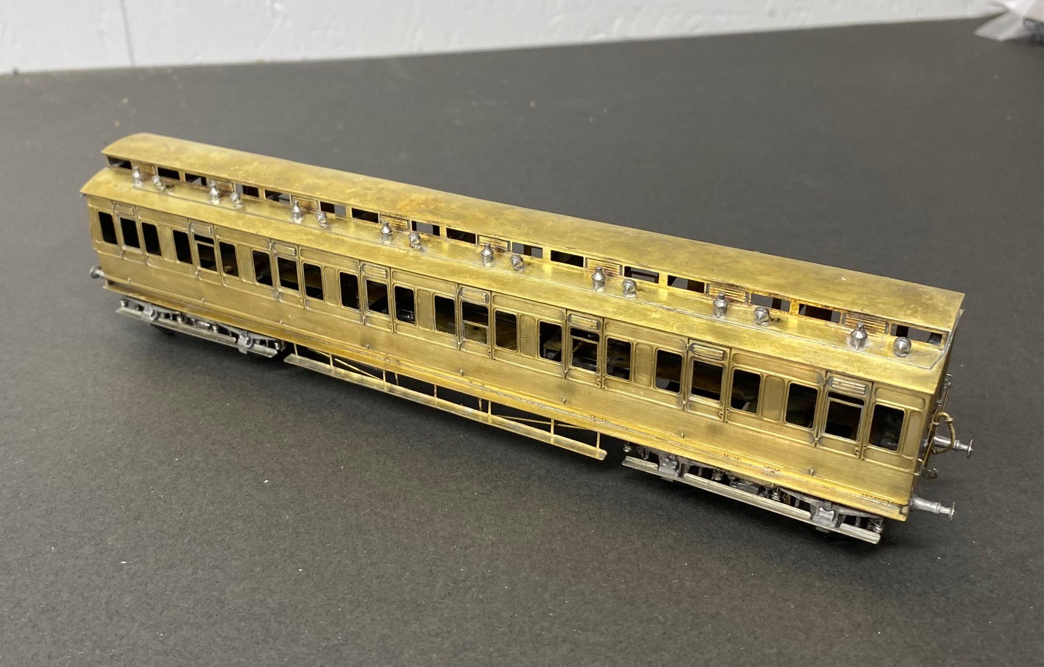
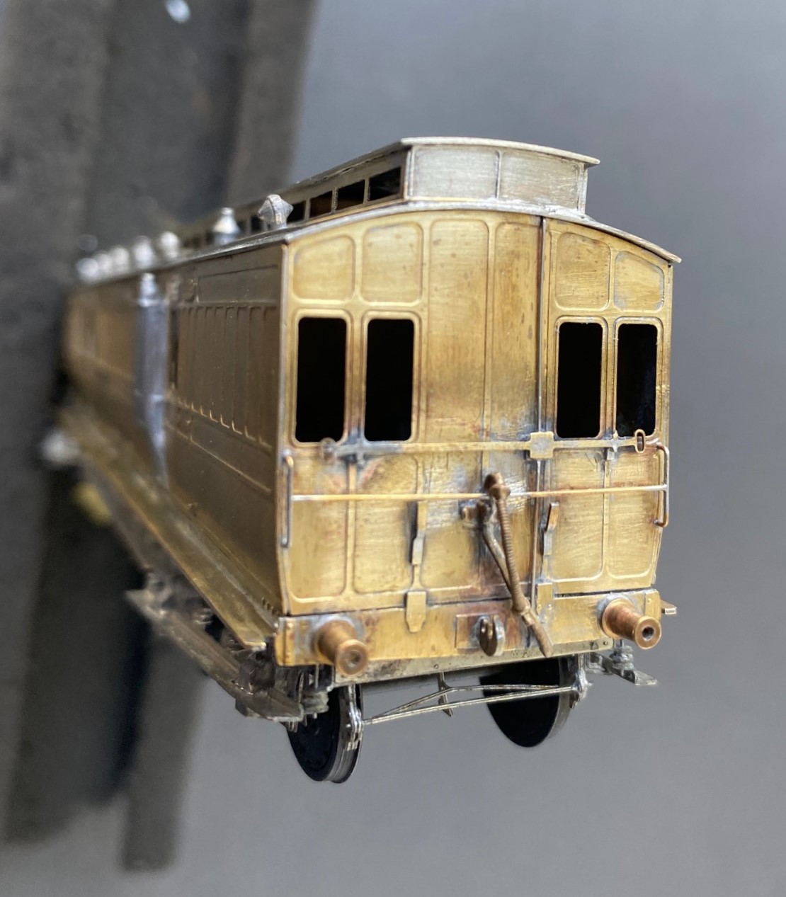
The rake only needed a modicum of first class accomodation made up from a composite diagram 7. Alas, this had a challenging problem that needed to be overcome, with the clerestory side pieces. These were much shallower than those on the other kits orwith the ends supplied in this kit. In addition to being obviously incorrect given the inconsistancy but the frames around the glazed lights were stunningly delicate. I regret persisting with this, i should have just drawn up some replacements in CAD and popped them in the next etching order.
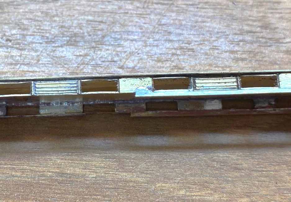
However, i solved the problem by soldering a flat strip, 1.5*0.5mm along the base. in theory it should be to both the top and bottom but that was not realistically possible and I decided life was too short. After much fighting, cussing, fighting, screaming and more fighting, I did get it there, as I hope you can see.
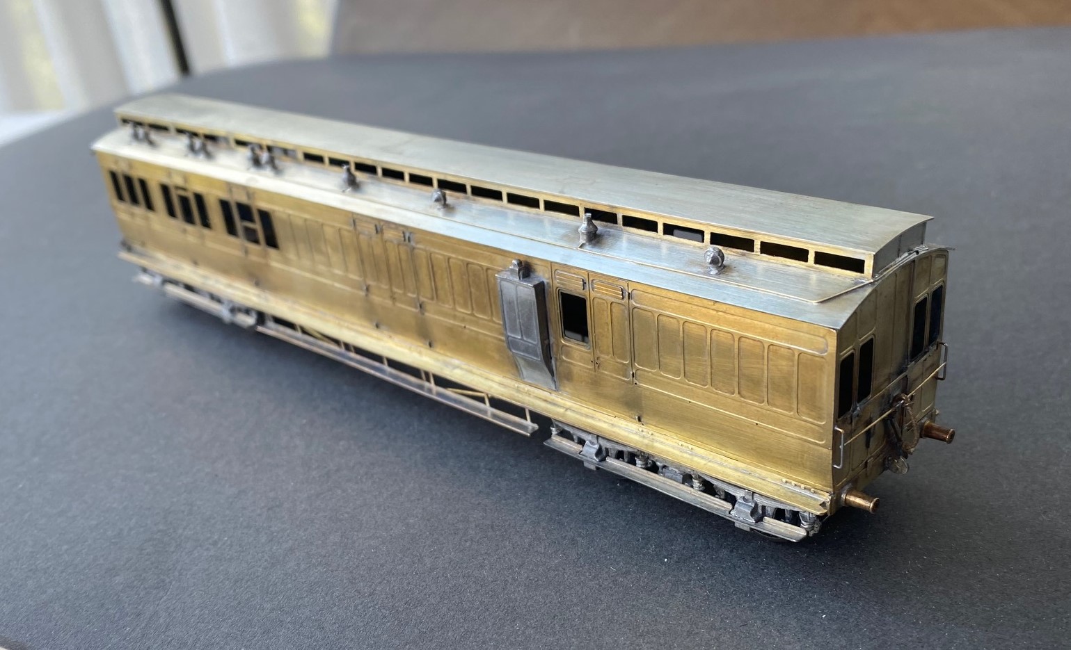
I was asked to do these as gas lit coaches and therefore there is a bit going on below, as one might say.
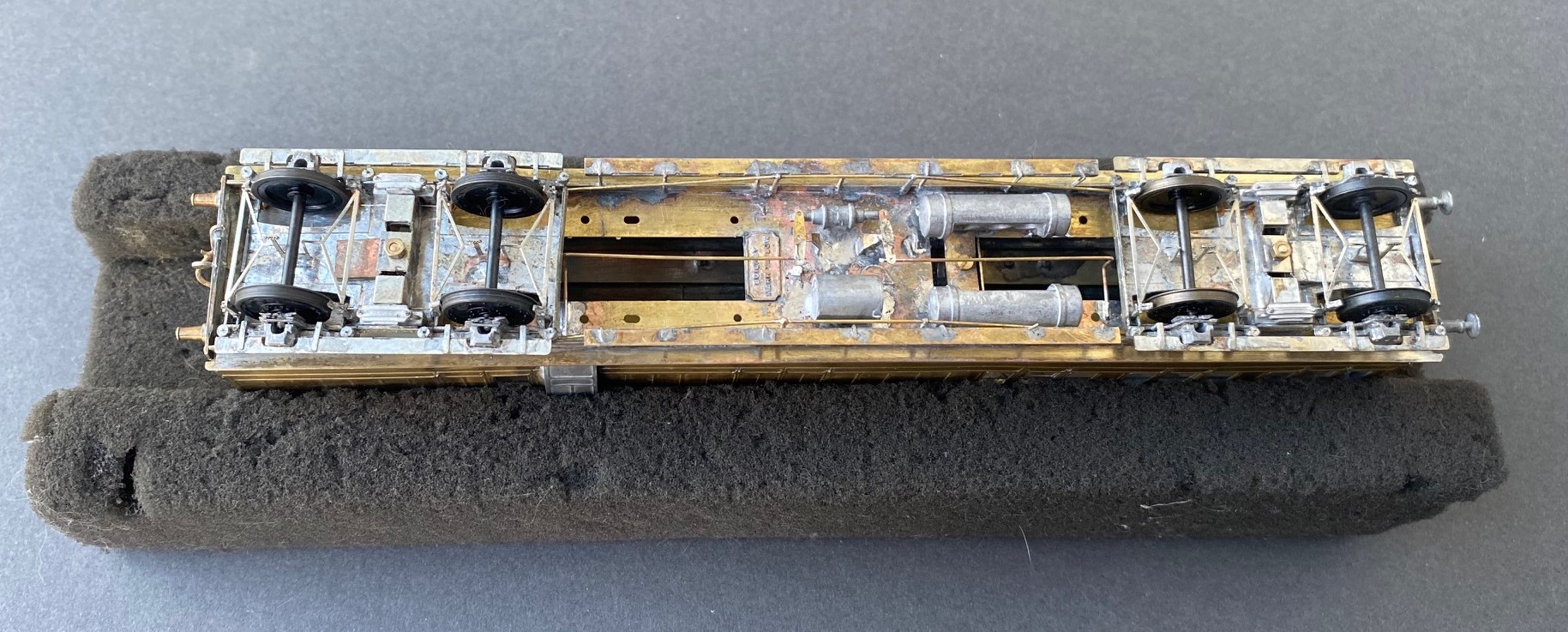
As the coaches were quite long lived, they went through many detailed changes. for anyoen who is contemplating building some, I would heartily recommend reading David Addyman’s notes on how he built his in the Scaleforu Forum https://www.scalefour.org/forum/viewtopic.php?f=39&t=7210&p=101662&hilit=ner+coaches#p101662 David’s coaches are modelled in the 1930s, so have different lighting arrangements, footsteps, bogie spring dampers and sides to the clerestories. Lots of things to be aware of if you are doing something similar.
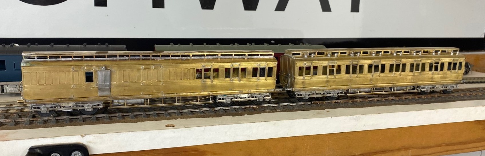
At the end of this rather mammoth build, I had four coaches that i was rather proud of. They look rather fine on John Wright’s Benfieldside viaduct.
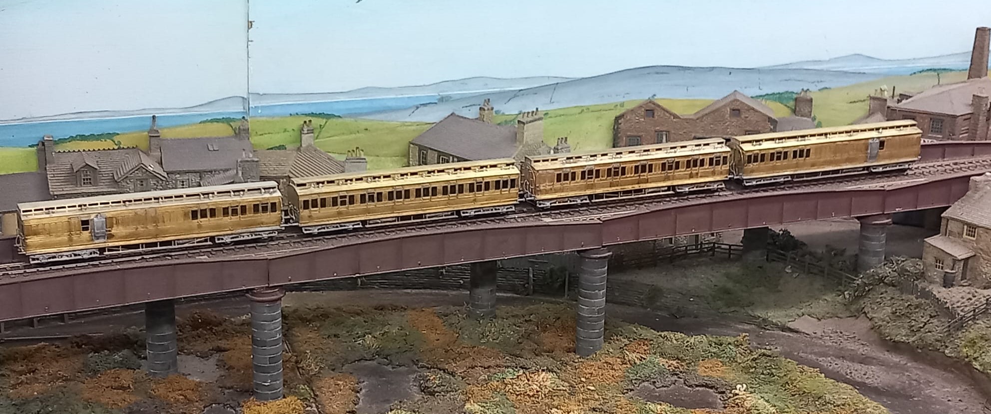
I am also pleased that i do not have to paint these; i am still looking for my lining mojo. I had it as a teenager, but have grown shy of lining. Maybe something for the Christmas break?
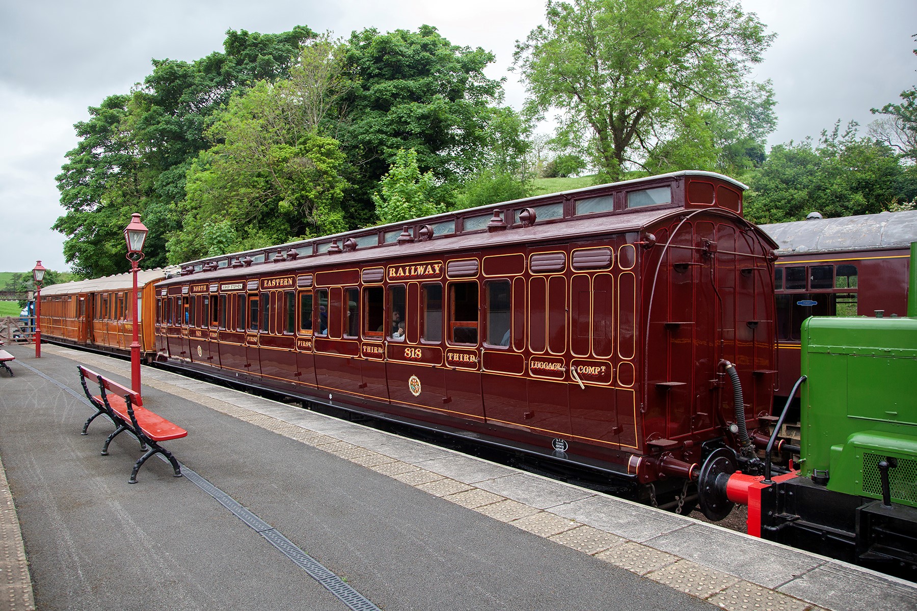
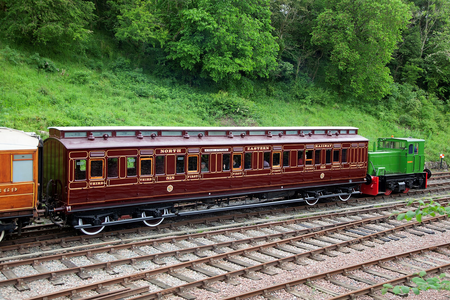
In the meantime, here are a couple of pictures of the newly restored NER coach 818 at Kirby Stephen, courtesy of the Beamish website. Does’t she look magnificant? I really must get up to see her.
The Other Benfieldside
To date, the images and details I have shown on Benfieldside have related to the main and original station. However, there is more!
Benfieldside’s original builder, John Wright, constructed a significant extension a few years after completing the core layout. This was shown at the time in the Model Railway Journal (issue 57, 1992) and has not really be seen since.
When John’s interests moved on, he disposed of both parts of the layout and in turn the new owner decided he did not wish to retain the whole. However, he elected to retain the extension in order to convert it to P4 as his home layout (Benfieldside was all constructed as an EM layout). We all know what life is like – jobs, family life and other priorities get in the way but progress is now being made. The two main lines are now operational, as these two videos show.
The new layout will be NER as a core, but with also a Midland presence. It appears that the Midland has provided the motive power for the test train!
As you can see, Benfieldside’s extension was centred around a substantial viaduct with a degree of siding to one end. Its owner is proposing to make a small MPD here, the beginnings of which are visible in the videos.
There is still a way to go both in the adjustments around the MPD but also in refreshing the scenery. But never the less, as you can see it is another impressive layout.
The Other Auto-coach
Some time back I posted about the construction of a NER autocoach that I was building for Benfieldside and subsequently what it looked like once painted by Warren Heywood.
The NER generally used these in pairs, with a loco sandwiched between, although they did go out singly and even as quads. In this case, the Benfieldside team wish to operate them as a pair, as the bay to the right of the layout is conceived to receive such a train, with a NER / LNER G6 in between. This means that there was pressure to build the second from the moment I handed the first over. They have recently given me a favour, so it was high time I repaid it.
It is now completed down to the final check over stage (which has indicated that I need to put the steam heating pipes on – doh!) and then it can be delivered. So I have braved the fading light this afternoon (so sorry about some of the depth of field issues) to take a few pictures and to prove to the fellas it is done!

I completed a few personal upgrades to the kit in both this and the earlier autocoach. Chief of these is around the roof where I ditched the plastic roof and replaced it with rolled brass. This was formed of 0.25mm to give it a tangible depth, which makes its rolling a fair challenge. Add to this, I elected to cut out the portion below the clerestory, so that it was a clerestory! By the time I had added the gas lines and the various gas lamps and ventilators, I reckon there is around 20 hours in making the roof alone!
The prototype coaches were fairly long lived and numerous. They thus collected a good number of alterations and differences over time. I took some guidance to David Addyman and tweaked the kit in respect of gas lines, foot steps, handrails, footboards and gas cylinders. If someone thinks this is wrong, please don’t tell me!!
It always amuses me that the driver had to stand and peer down the line through two tiny windows. They lived in different times – could you imagine the snow-flakes tolerating this in the 21st century?
These are rather beautiful coaches, but not for the feint-hearted as there is a lot of time invested in these. I am pleased I do not have to paint it!
A Ransome & Rapier Crane
Readers of this blog will recall that my father has a significant interest in breakdown cranes; he has published a series of books on them and is the honoury president of the Breakdown Crane Association. As a result of this, a few years ago, he took a call from Bachmann when they started to research the possibility of filling a gap in the ready to run scene for a accurate breakdown crane. He delighted in being sworn to secrecy on this until the model was announced and now, some five years later, it has finally arrived on the shelves.
So after a somewhat unsatisfactory retail experience with Rails of Sheffield (which I won’t be repeating, there are plenty of other retailers out there), an example of a Ransomes & Rapier 45 ton crane arrived not much more than a couple of hours spare so that it could be parcelled up in its Christmas wrapping for my father. Now that it has reemerged, it is time to take a look at it.
Prototype
The prototypes originate from the early years of the last world war and were initiated by the British Government; in part in anticipation of a lot of emergency repairs being required following enemy action and also for use on the continent once a toehold had been achieved. Initially a total of six were made, going to the SR and GWR but subsequently a further order of nine were made, mostly for the military but with a couple for the LNER and another for the SR. The example I bought being from the latter batch, being initially based in Gorton on the ex GCR system.
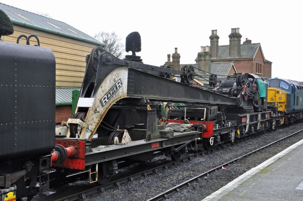
There were detail differences, with many of the railway company vehicles utilising standard components from their eventual owners. The valve chests for the cylinders moved to the exterior in the later batches and the operation of the loading of the relieving bogies became hydraulic latterly. The biggest changes, however, related to the match wagons where there was both variety of arrangements of tool boxes at the time of building and generations of modifications thereafter.
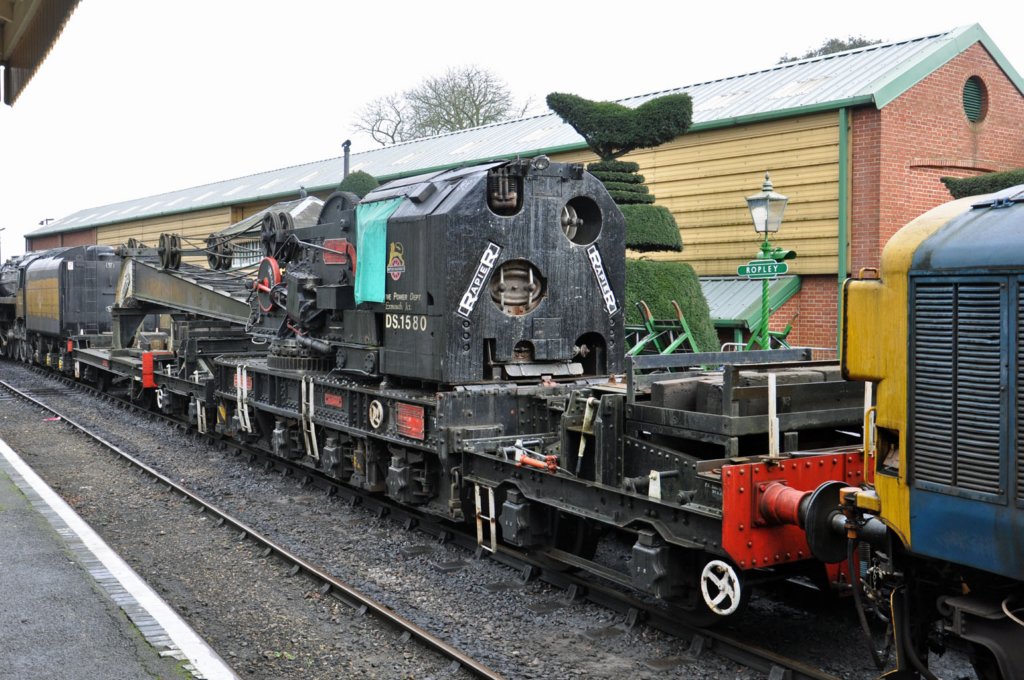
The cranes lasted until the mid 1980’s and a number of them survive in preservation, so if you want to see the real thing you might want to head to the Midhants Railway (on which the prototype photographs were taken and reproduced with kind permission of Carl Watson), the Bluebell Railway, the Great Central Railway, the North Yorkshire Moors Railway or the Swanage Railway. Below is a link to a video of the Midhants crane in action:
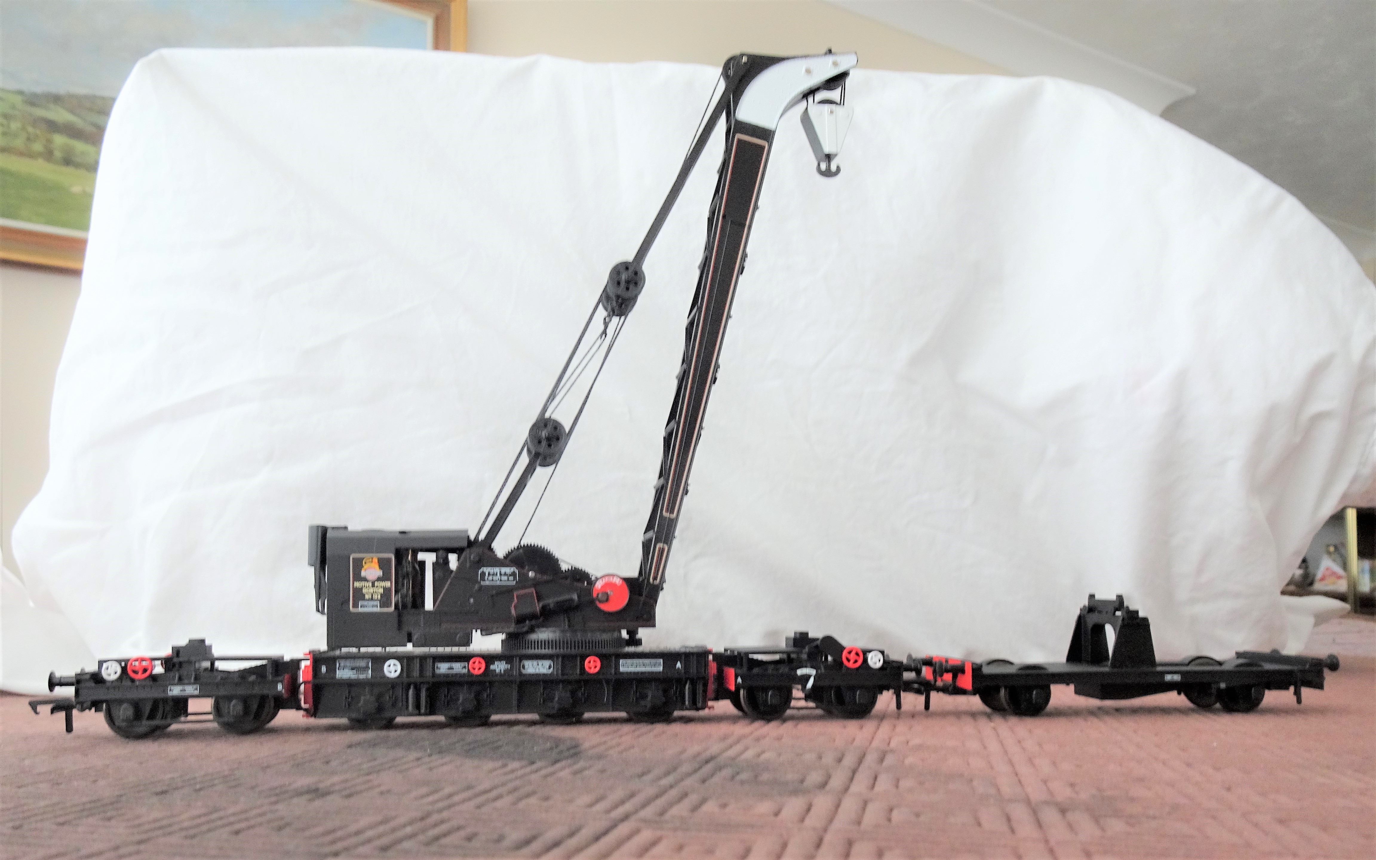
Model
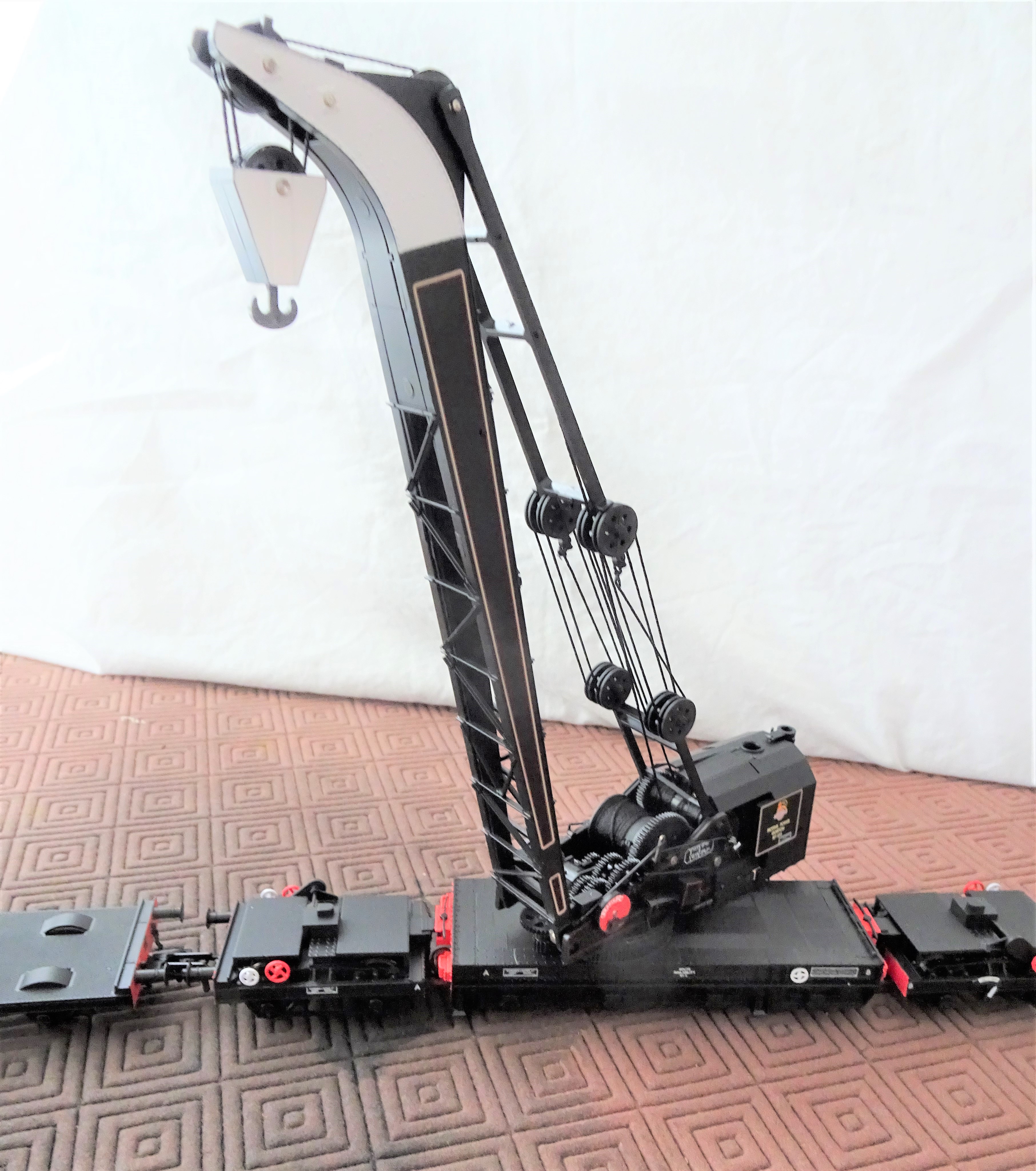
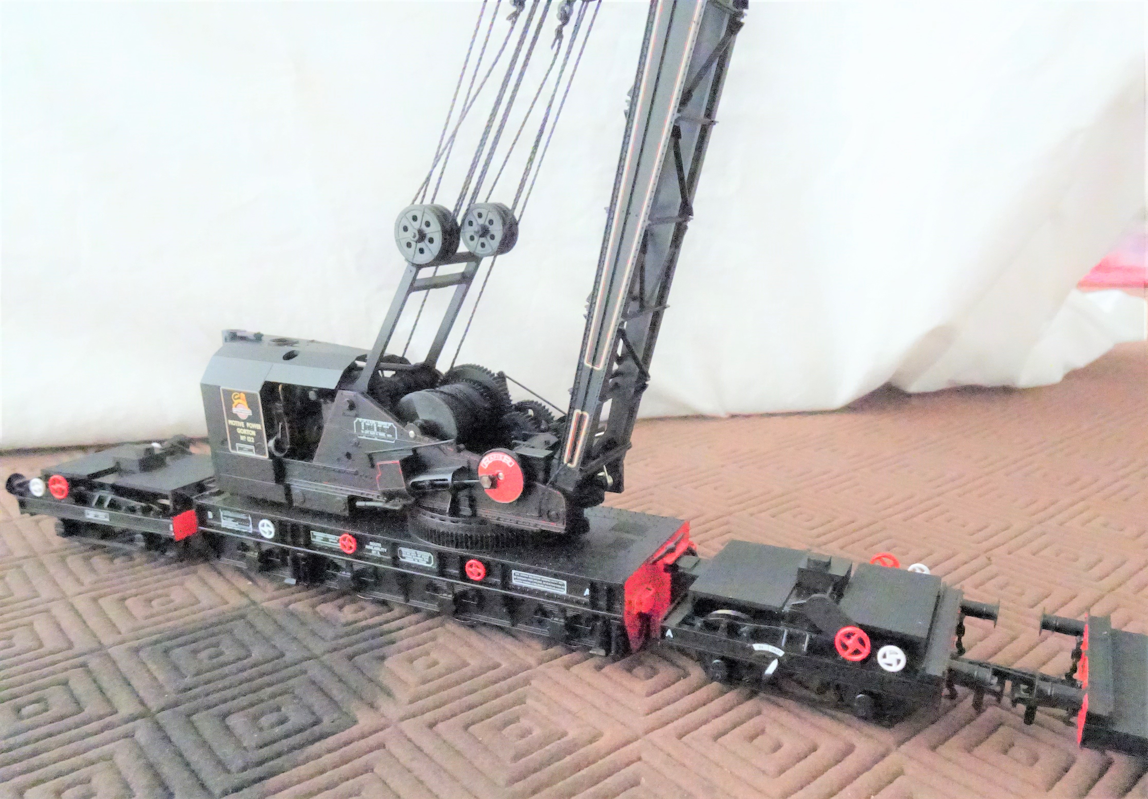
The first thing you notice with the model is that it is some way from the toy train end of the model train market. The prototype is smothered in detail; with the fine bracing between the sides of the jib, the gear trains, axleboxes and flywheels all being a bit out of the ordinary for the ready to run market. Bachmann have had a really good go at this and for the greater part they have got it right – very few could model a crane as well as this. There are, however, several compromises made to enable them to be operable. This particularly shows at the bearing points at the head of the jib (exposed metal when they shouldn’t be visible) and on the crankpin nuts to the flywheels (way too big and hexagonal). I understand why this was done, but it sticks out to my eyes! Some touching in of paintwork will help (but not be perfect) and the replacement of nuts with something more subtle should be possible.
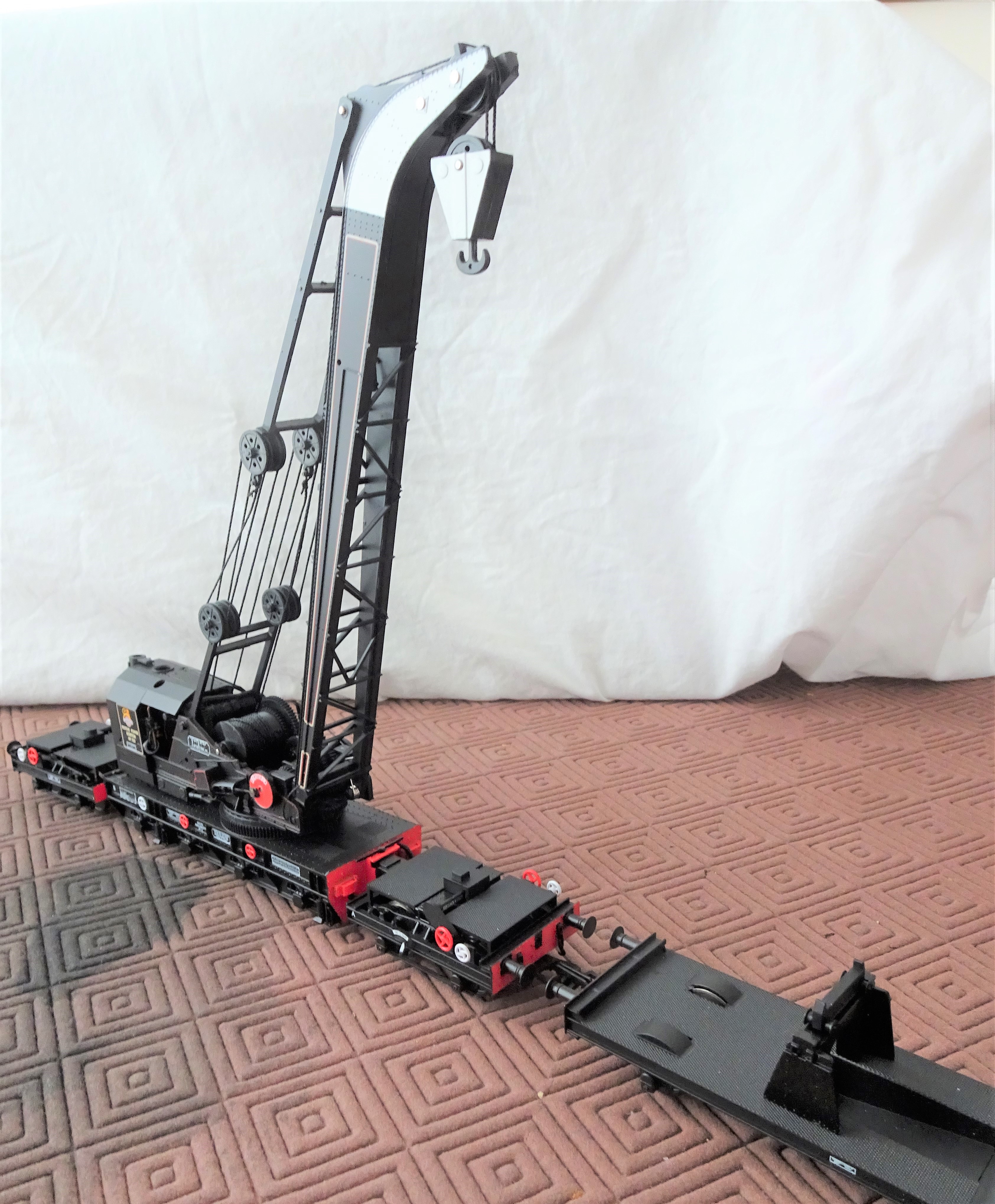
The detail is very delicate and the model needs to be handled very carefully as a result. Even the most careful (and I don’t count myself in this group) are unlikely to keep all the detail in place on any model that does not merely sit in the display cabinet. With a recommended retail price of £250, substantially more than any other product that is not filled with motors & electronics, it is doubtful that too many will end up in the hands of children – maybe that is just as well!
The model I bought, the early BR model in black – Bachmann ref SKU: 38-802, has a match truck without tool boxes. This is correct for the specific crane post the early 1950s but what is not is the missing insides to the splashers. This seems to be a compromise to accommodate OO wheelsets without making the splashers excessively deep. It is easy enough to fill in the open spaces if you model in one of the wider gauges and it will make a big difference.
The painting and livery is particularly fine on the model. Even better there are some exquisitely delicate etched plates that can be applied on top of some of the plates. I suspect I see the shadow of Mr Hanson on them.
Options
It looks realistic to get P4 wheels into the crane underframe and definitely so for the runners/match wagon. I would, however, be concerned as to whether a four axle vehicle could survive all but perfect track in P4 and how many of us have that? I suspect that it will all be very tight too, so some pretty large radius curves would be needed if a P4 model can get around them. Of course I will have a go, but it is not high on the to do list at the moment!
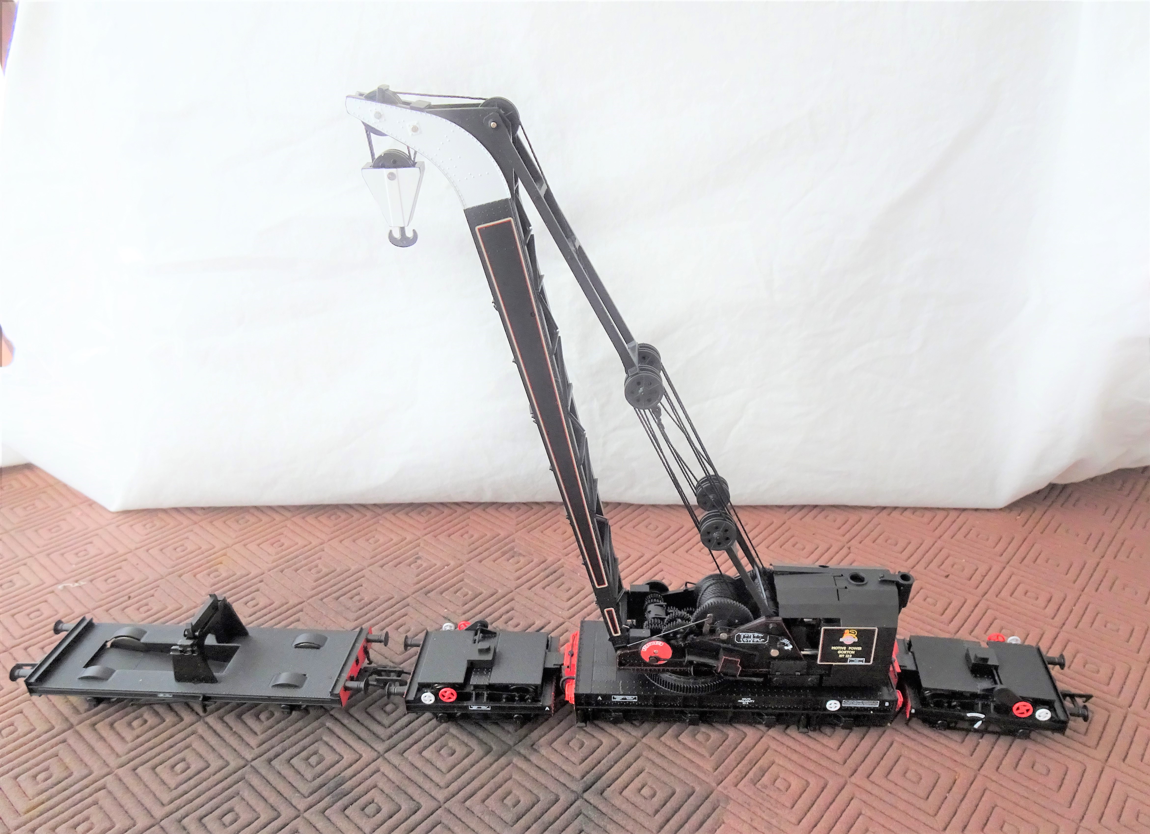
I think it is only a matter of time before someone looks at trying to motorise the crane. I think I will say good luck to them! Getting micromotors in might be possible for at least movement along the track but that still leaves slewing of the crane deck, raising of the jib and raising of the hook to go – getting another three in looks pretty difficult to me! The model does include internal hand operated mechanisms for the latter two movements – there are access panels that pop out to reveal a socket to receive a hand wheel. Thus, it is realistic to stage scenes, but not (in my eyes anyway – I really do look forward to someone having a go!) to make a fully operating model.
What is a must though is to add the paraphernalia of clutter the real cranes acquired in operation. Photographs show that they typically attracted lumber sections, jacks, chains and tarpaulins as if they were magnets. Cranes, not being front line stock in the public eye, tended not to suffer repaints very frequently and as they stood outside, they did weather and pick up corrosion spots. So any self respecting modeller needs to do something about how clean they look.
Although there is a very long in the tooth model crane from Hornby, it is somewhat of an uncomfortable marriage of several different cranes (the really old Hornby Doublo diecast version is better but quite crude), so does not cut the mustard. There are a limited number of kits for other cranes – notably the D&S Models Cowen Sheldon 15 ton breakdown crane (an example of one might grace these pages eventually!) but these are full on kits. Thus Bachmanns cranes are not only attractive models in their own right but they have a field fairly clear of competitors.
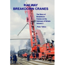
If you want the book on the prototype you need volume 2 of my father’s book – at present it is out of print but it is hoped with a bit of pressure on the publishers, Crecy, they can be persuaded to do a further print run.
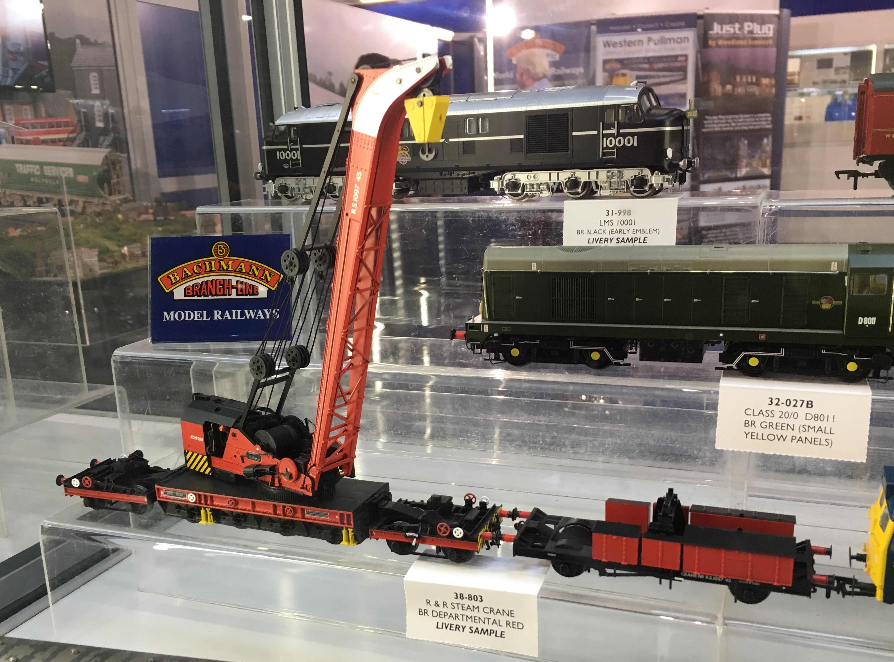
The Bachmann crane is presently available in an SR livery, a GWR livery and then a pair of BR liveries – the 1950s livery shown above and a later gulf red livery. An example of the latter is below:

Controlling Bottom Works Sidings
Followers of this blog will probably be aware that I share some of my model railway escapades with the two authors of the blog OTCM. Both of the authors are in the process of putting together entries into a competition to build cameo layouts being orchestrated by the publishers Titfield Thunderbolt. Cameo layouts was the topic of a book written by Ian Rice and seeks to describe a small layouts seeking to use presentation techniques to capture a slice of the whole in a convincing manner.
To be fair to Oly, his entry is largely complete as long as he does not seek to tinker with it too much(!), the same could not be said for Chris’s entry – titled Bottom Works Siding – so he has some catching up to do! To assist Chris I offered to make his signals and after a few weeks of work we have reached the point where they are complete.
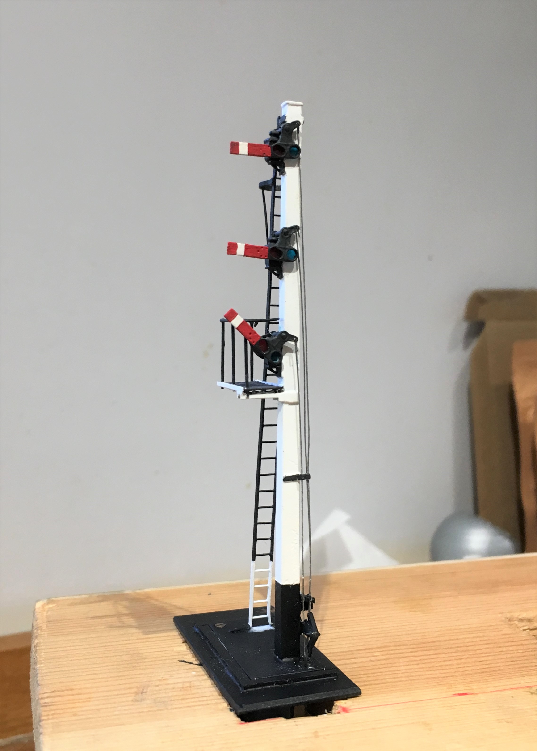
Chris’ model is based on the GCR’s route over the pennines at its Yorkshire end. It will represent a set of transfer sidings from the Woodhead route electrification to a industrial line serving a coking plant – so I suspect we will get to see a fair amount of grot in the finished article! Its signals are LNER or BR(E) practise which is mildly different to what I have built before in some regards but not others as there was a lot of standardisation between the LMS and LNER (and BR more or less adopted LMS practise). So first up (above) is an LNER standard wooden post with replacement BR miniature upper quadrant arms. The post is a piece of brass square section that I filed to a taper (hard work) with predominantly Masokit’s fittings (which I found to be notably better than MSE’s equivalent).
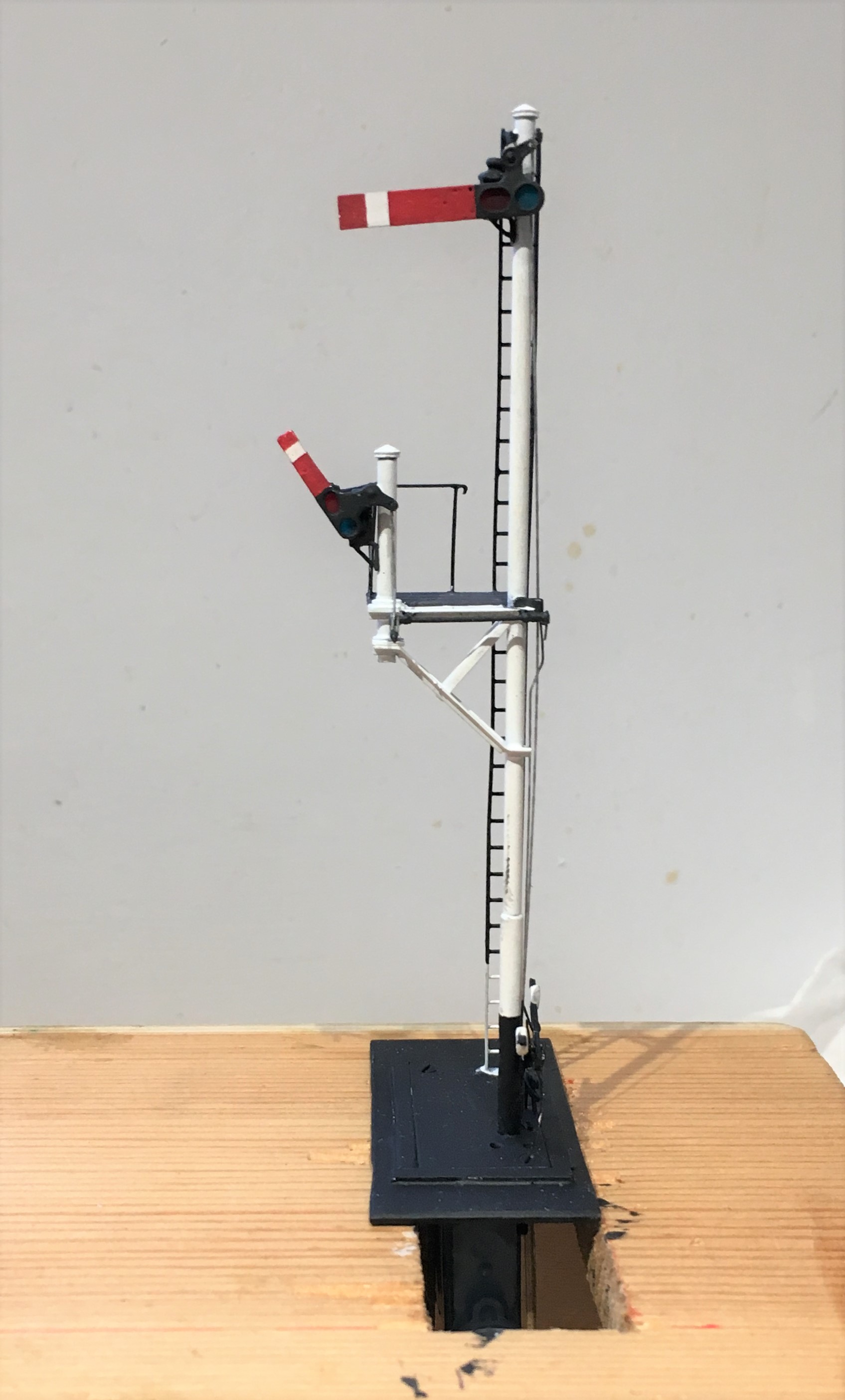
This one is effectively a standard LMS/BR tubular post signal (apparently with brewer’s droop – sorry!) with a small bracket that has another miniature arm signal to it. This is assembled with a combination of tubes and angle section from Eileen’s Emporium, along with some more Masokit’s arms.
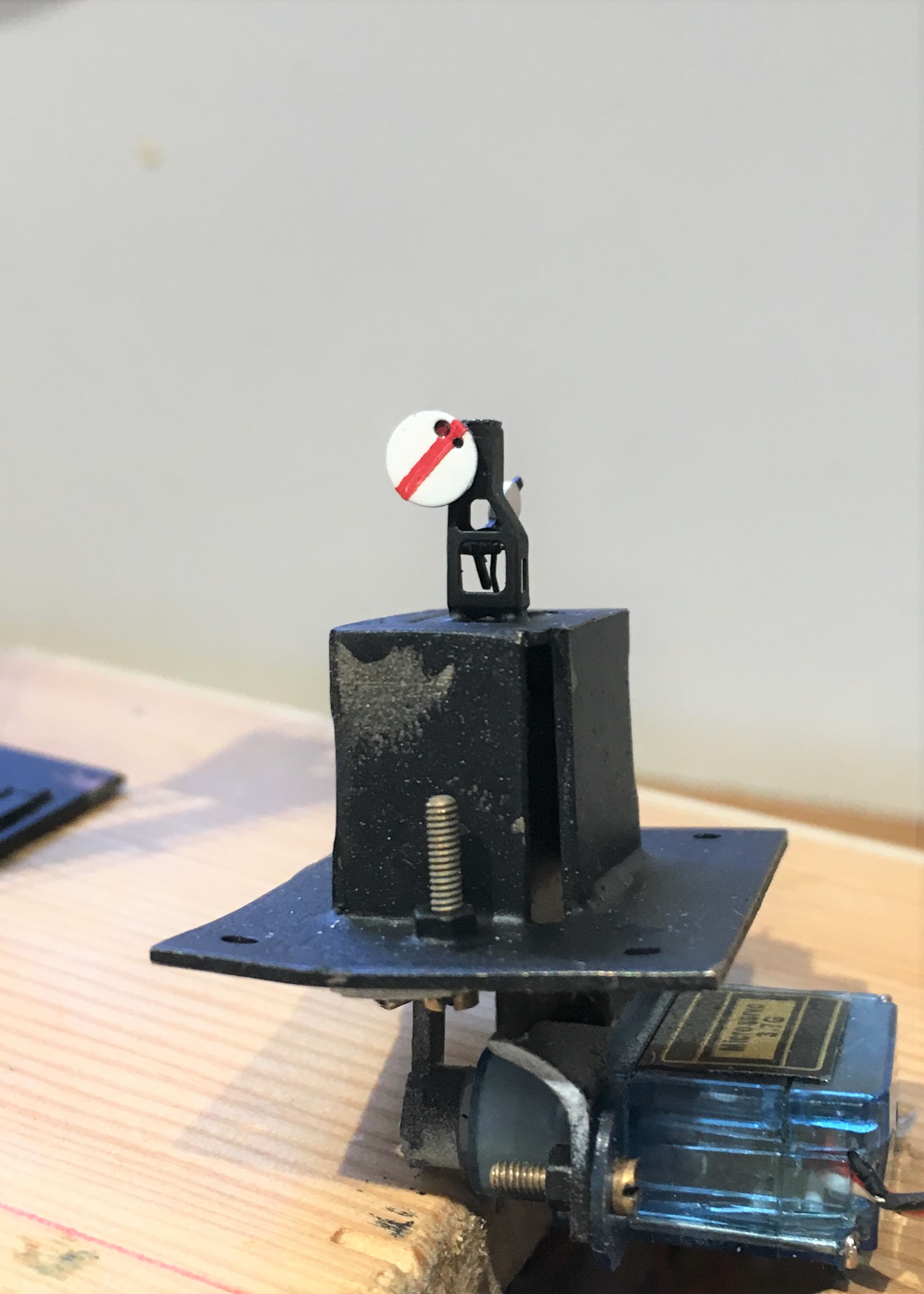
And finally a miniature ground signal – which despite being startling small was not actually all that difficult to build – it being based on a excellent little etched kit from Palatine Models.
As a result of a lost camera, there are not really any meaningful photographs of the signals being created but fear not, I still have a few to go for Glenmutchkin, so there will be some to come! In the meantime, and to prove that they really do go, here are some videos.
In the fullness of time, I dare say we will get to see these in situ, so why not subscribe to Oly and Chris’ blog, to get an instant notification?
NER Hoppers
I am presently cracking on with a batch of NER hoppers for Benfieldside. Having acquired the layout, Tim and Julian have very little stock to run on it, so as part of the repayment for the use of their facilities and expertese on my boards, I thought I would help to correct this shortfall.
The origins of all of this present batch of hoppers all go back to the Slaters’ injection moulded kit, which is of diagram P7 wagon. There were around 17,500 of these wagons at the time of the grouping and the LNER carried on building them for some years thereafter with only subtle differences; so not unsurprisingly there were quite a lot of variants. Thus, I have been doing a lot of modifying!
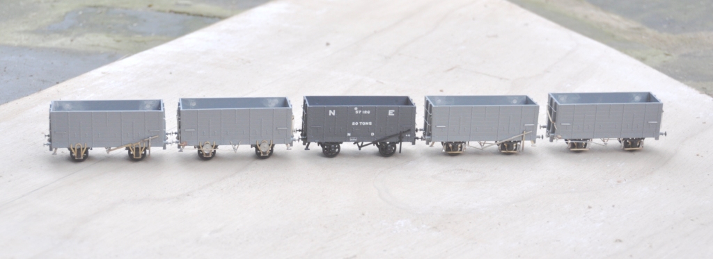
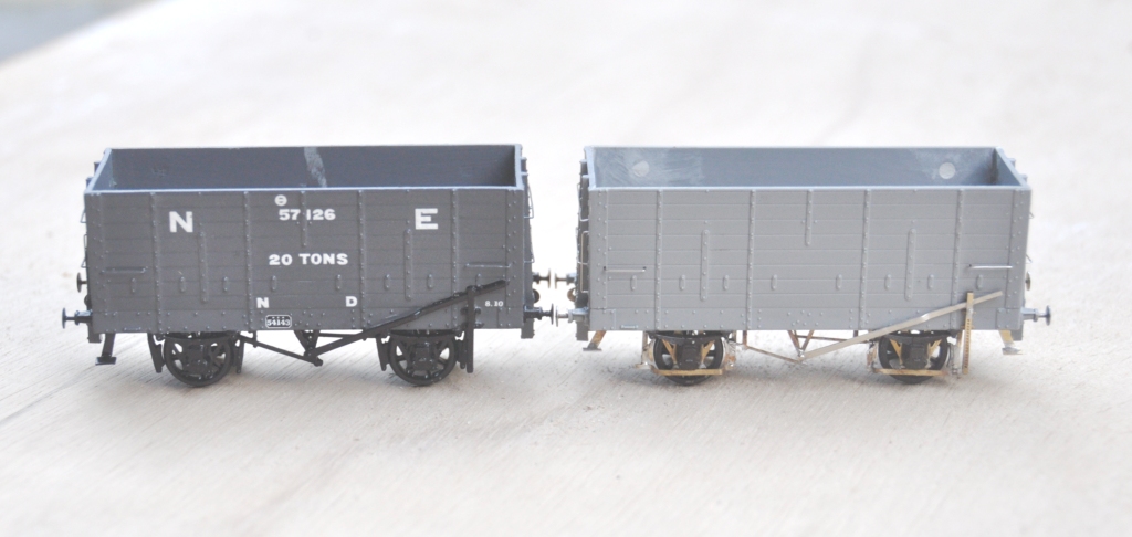
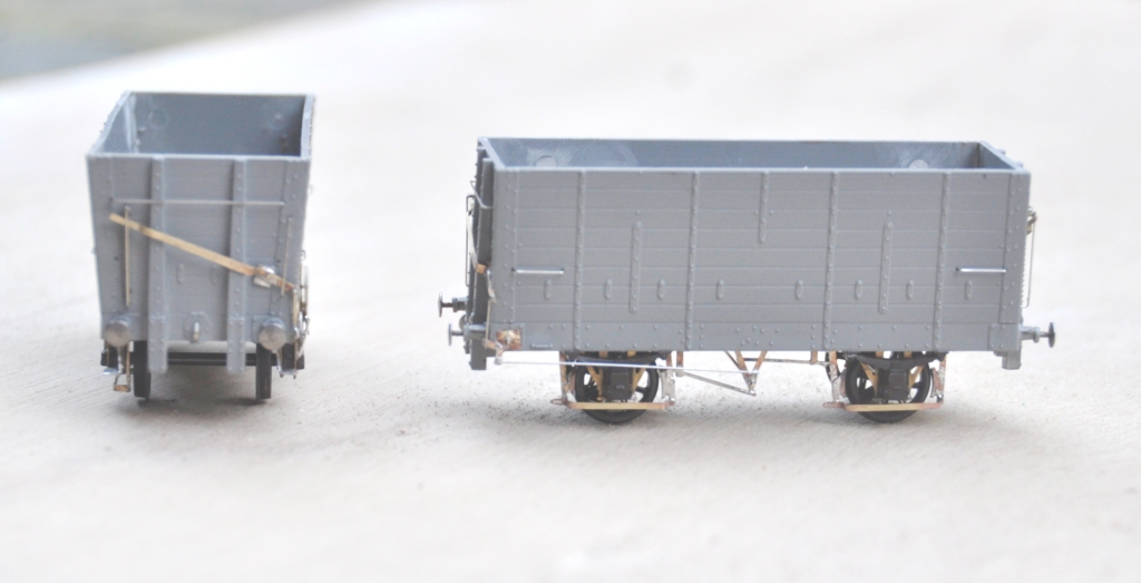
In each case, I replaced the very clunky W irons with Bill Bedford replacements; even though these were to be to EM, I felt that they would improve their performance. The first examples were essentially built as the kit was intended with fairly traditional brake gear (which was to one side only). However, having built my first one, I decided to refine the brake gear by drawing an etch for replacement steps, V hangers, morton brake mechanisms and brake levers. This (along with a comparison with the plastic equivalent – the painted wagon), is below:
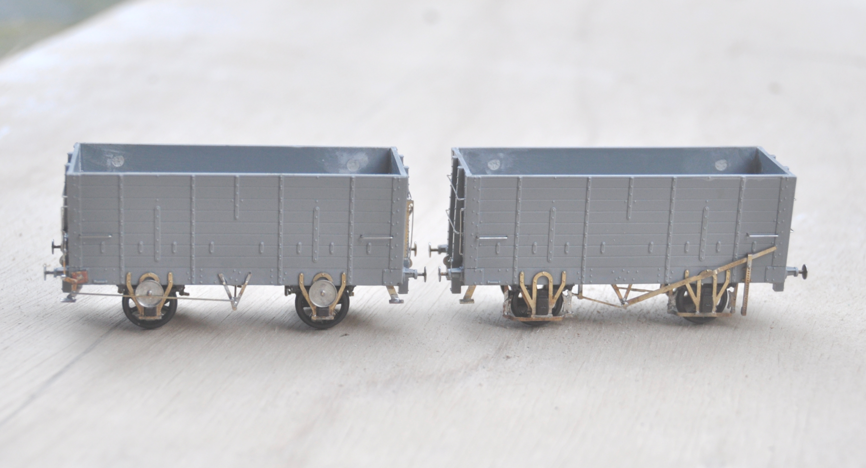
However, a significant proportion were modified with end levers that operated a crank that was connected to the Morton gear. At the ends, there was a much more chunky ratchet arrangement to retain the lever in position. Again, I drew this up on the etch, and the arrangement looks like this:
The NER undertook a number of experiments with these vehicles to attempt to reduce rolling resistance and this was the subject of my next modification. On the right (below), shows the provision of a second outside set of W irons. This was to add stiffening to the axles. There is a set of Bill Bedford W irons to cater for this, but I chose instead to create a fresh set on the etch. On the left is a further variant, where an anti-friction bearing was added in addition to the outer W irons. This was a wheel that ran on the top of the axle and I presume the idea was that as it rotated less, there would be less friction. I suspect that the introduction of an open bearing surface that would instantly get contaminated with coal and grot would actually have the exact opposite impact – as these were removed by the grouping era, I may well be right!
The final variation of construction that I have modelled was a slot cut into the ends, which appeared on some vehicles. The NER used these on vehicles that were hauled up rope inclines – of which they had many. A plank of wood was inserted into the hole and wedged such that it was secured behind the end posts to ensure that the haulage point was close to the centre of the wagon. They found without this that there was a tendency to pull the end posts loose due to the uneven point of pressure.
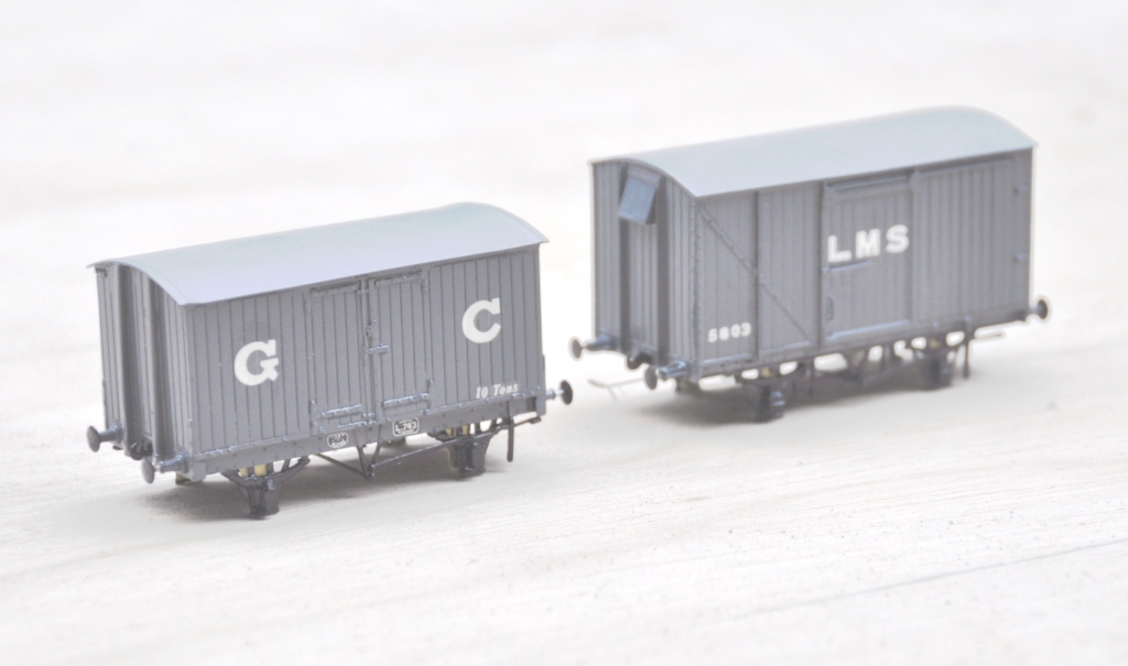
Next up will be the painting and lettering of these; where I have three eras to chose from that would have all been apparent immediately pre- first war, which is when Benfieldside will be set. More on this in a future post.
If there is a desire from anybody for the etches, I would be able to offer them; so drop me a note?
