Scrap Tank Test Build – Part 4; Beginning the Chassis
Putting aside the body for a while, to take a look at the chassis because it is necessary to mount the two together and it is not possible to close up some of the element of the body until this is sorted out.
As with the body, I am trying to take a moderately fresh approach to the chassis to make this a little easier to build than certainly most of the kits I am used to. In this regard, most of the kits for the Highland are quite traditional in their design and I readily admit that all but two of my ideas has been either all out pinched from other designers or at least significantly inspired by them. All I am trying to do is use more of these neat ideas in a single kit to make the life of the builder easier. I am, however, finding that it makes my life more difficult, as there are a lot more moving parts to most components, so more places for the tolerances to be catered for; so as John Price has already said, the list of little tweeks and amendments to make is growing! At least, no one can say this particular kit designer has not built their own model.
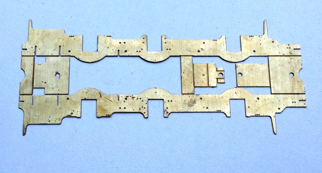
Anyway, this is what the chassis looks like in the flat; note that it is a fold up design – this is inspired by the Mousa Models chassis, so a pinched idea!
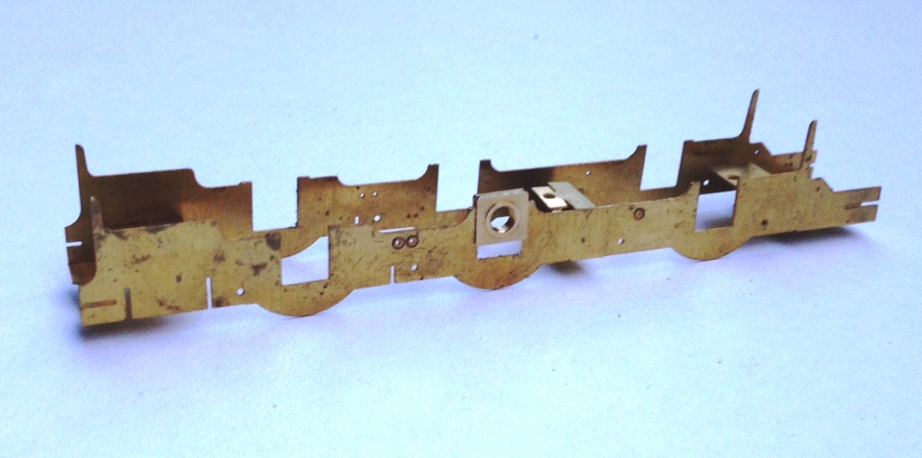
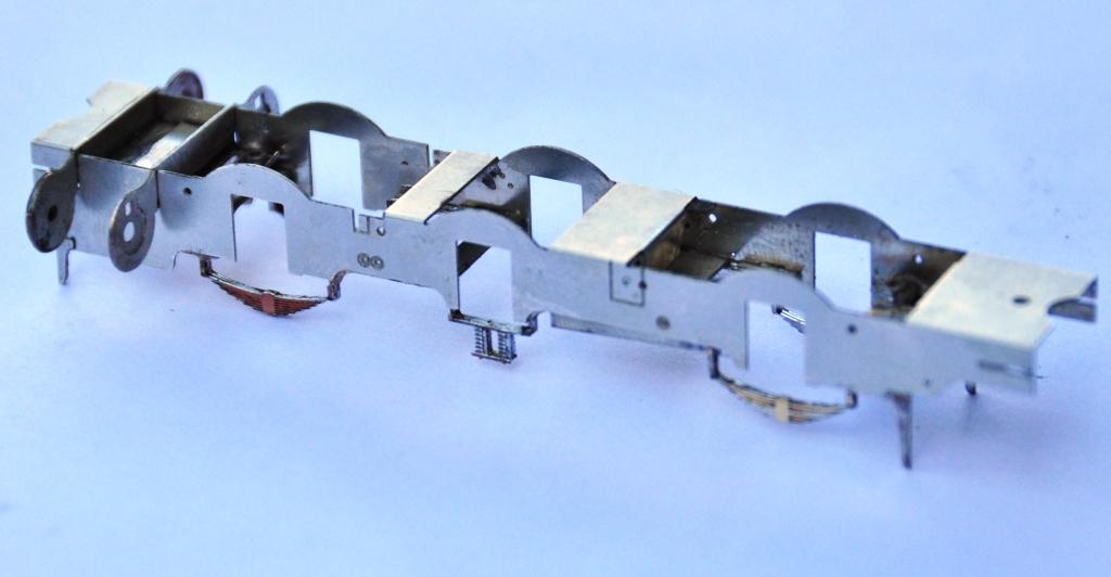
And this is what it looks like with the basic folds made up. What it achieves is really neat, as it is instantly sufficiently stiff to work as a chassis; by the time a couple of further cross braces have been installed the basic chassis is more than robust enough for its life.
My design uses the same slide in hornblocks as utilised by Comet and Brassmasters for their chassis. After a tiny bit of practise, it is possible to size the hole for the hornguides such that these are just too small when etched. This means that with a few strokes of a light cut file on each side, the hornblock becomes a tight sliding fit. Once all of the hornblocks are in, it is then possible to measure the distance between each on both sides of the chassis and also on the corresponding coupling rod. This is done with digital callipers and by the expediency of measuring the distance at its maximum with the callipers facing outwards and then repeating with them facing inwards the average being the actual distance between the centres. I reckon to be able to measure down to 2 or 3 hundredths of a mm, which is rather better than I can build to! Where there are inconsistences, this is dealt with by a few more strokes of the file on the side which needs to be adjusted to change the centre. This needs to be done anyway to turn the tight sliding fit to a snug but smooth fit for the hornblocks to work properly soif the centre does not need to be changed, the file strokes are undertaken equally on both sides of the hornguides.
This does need to be done after the coupling rods have been formed, of which we will see in the next posting. However, the chassis is also designed with a keeper plate to accommodate all of the cosmetic springing to the model and the ashpan sides. This is secured with a series of 12BA screws to enable it to be removed to allow the wheels/axles to be dropped out. A great boon as the model is built and painted.
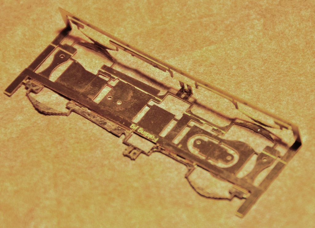
To make the assembly of this element easier (in fact in this case a lot easier!) I have created a jig that holds the two layers of the laminate in exactly the right position. The jig is chunky enough to avoid distortion as it is folded up and it locates the parts perfectly. In this particular case, the soldering needs to be done with care as there are folds to make after the jig is cut away and it is important not to fill this with solder before hand.
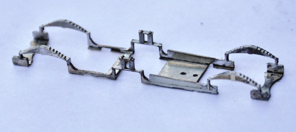
And this is what the keeper plate looks like – it is pretty delicate until it is mounted but fine thereafter.
And the two components assembled look like this. The beginnings of the cylinders are also visible, this is a slide in module that can be removed for assembly and painting (although the scrap tanks were painted fairly simply, so this is not really relevant on this model).
Posted on April 7, 2015, in Miscellany Models, Workbench (other) and tagged brassmasters, EM, etching, highland, Highland Railway, Miscellany Models, Model Railway, Mousa Models, Peter Drummond, Scrap Tank. Bookmark the permalink. 3 Comments.

Mark, the folding jig and drop out module for the cosmetic springing is excellent, I am really impressed with the evident amount of thought that has gone into your design. The fold up design of the chassis looks good. Looking forward to the next installment.
Hello
Exelent job on this loco. Would you consider posting the etch image and any CAD images to help future designers?
Thanks
Ross
Ross,
I will do so once I have revised the artwork (which will be a little while yet) to correct the bugs I have found with it. I will make it a fresh post when I do.
Mark