Tatty’s Top Tips – Signals
A mere three weeks ago, but a lifetime in the past now that we are in the middle (or more worryingly, perhaps just the beginning) of the Covid-19 crisis, I was a demonstrator at the joint EMGS/Scalefour Society skills day. These skills days are not really exhibitions and are instead aimed at passing some skills on to the visitors – thus they are primarily a hall full of demonstrators with only the odd layout or two to break up the rows of desks.
Here I am, in a shockingly creased shirt (!), and as you can see, I am demonstrating signal construction. I am pleased to say that at the skills day I had a solid stream of people engaging with the topic all day; so much show I had to pull down the shutters for a brief lunch as otherwise I really would not have stopped all day!

By way of preparation for the event, I thought about what I have learnt about building signals and distilled a list of my top tips. These proved to be the cornerstone of my conversations with people at the Skills Day so I thought it was worth repeating them here on the blog.
Planning Ahead
- Conceive how you are going to mount the signal; where and how, what is above the ground or below the baseboard – which might well mean you also need to;

The base and mount for a two movement servo controlled signal
- Decide how you are going to operate the signal, how is the drive mechanism to be mounted and what does it need to be connected to mechanically/electrically;
- If you are going to illuminate your lamps, you need to decide how you are going to run the wires to the LEDs or fibre optic cable. It is possible to use the post as a common return but you still need one wireway;
- Consider how the movement is to be transmitted (especially bracket signals) and how you are going to replicate this? Multiple movements in close proximity to each other can lead to interference, compromises to reduce this risk are sometimes desirable (especially for triple or more movements in close proximity);
- Conceive how you are going to paint and assemble the signal before you start – it is generally easier to paint arms and ladders before you assemble them so it is possible to create sub-assemblies to be attached later – the touching in of local areas of damaged paint caused through assembly is a small price to pay for the ease of painting the remaining areas;

A Southern rail built home signal; the post was formed of two pieces of nickle silver rail.
Construction
- Tight, tight, tight – the most important part of building a signal is to keep all holes of operating parts as tight and snug as possible as slack leads to sloppy movement;
- You will use a lot of fine drills, down to 0.3mm, and a good quality pillar drill will mean you break rather fewer of them!
- Use the file up the length of the post not across it as much as possible – the files leave less scars and any that do occur mimic the grain of the wood;
- Pre-form or pre-drill elements such as balance weights, holes to the posts or landings early on before they are assembled when it is easiest (well potentially!);
- The prototype of most of the components to a signal are pretty delicate with fine sections; thus, to capture their character these needs to be similarly fine, however:
- There is a trade-off to make with the operating components such as balance levers which are typically best made over scale and with laminated brass to give them more strength;
- Generally, build the bigger more robust elements first and potentially alter the build sequence in the light of thermal mass and whether adjacent items might be disturbed by later additions – consider using different temperature solders and prefabrication of elements such as dolls with all of the lamps/landings finished;

A prefabricated doll and arm – I wouldn’t normally fit the arm until after painting but this is not true for slotted post signals
- Don’t use the flat etched ladders, they are too flexible to look real. Either use the built up versions or solder 0.3mm wire on both front and back of stringers and file the outside face flat – they look more realistic and are more durable.

A flat etched ladder with 0.3mm wire being soldered to the stringer
- Lots of delicate parts and complicated sections means that ultrasonic baths are really helpful for cleaning without damaging elements;
Slotted Post Signals
- Not the easiest because of the need to solder the arm to the spindle inside the slot. Use a laminated piece to the ear that is the point at which the operating rod attaches to the arm and extend it cross the back of the arm by 3mm so that it is would project beyond the slot slightly. Be liberal with the solder but make sure that the rubbing faces are cleared of any excess. Wrap the arm in cigarette paper and insert it into the slot. After the spindle has been inserted, touch the cigarette paper with light oil and allow it to soak through. Then put a little flux on the laminated ear and apply the iron. The heat will transmit along the solder joint and reach the spindle.
Operation
- Protect the signal from excess throw; they are delicate – therefore set the servo up to an approximate centre point through before connecting it to the model;
- Leave room to be able to see the signal as you are setting it up, otherwise it takes ages and a lot of bending under the baseboard;
- If you are going to illuminate your signal, understand what the right colours would be – oil lamps are relatively dim (so you need to resist down the voltage) and quite yellow (so modern LEDs need to toned down).
Dimensions
Dimensions were not standardised even within a company, let alone between, so offering directions on dimensions is dangerous – all I will say is these dimensions are commonplace:
- Single post wooden signals – 6” square at the top and then tapering out 3/16th of an inch for each foot of height (1.5% or so)
- Wooden doll posts – 7” square at top and tapering as before
- Main post for wooden bracket signals – 10” at the top and then tapering as before
- Single post tubular signals – 5 1/2″ to the upper portion and 6 1/2″ to the lower portion. The height of the lower portion varied with the height of the post (for details, see LMS journal no 4)
- Arm – centre pivot – 1′ 6″ from the top of the post; second arms 6′ 0″ below that;
- Spacing between dolls – 6′ 0″ or 6′ 6″ (less for shunt arms)
- Height of handrail to landings – 3′ 0″
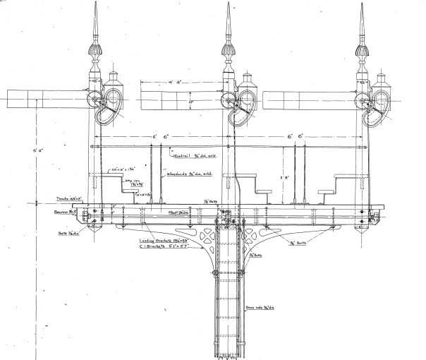
A GER three doll bracket signal
Posted on April 11, 2020, in Workbench (other) and tagged EMGS, Model Railway, Model Signal, Model Trains, ner, Rail Built, Scalefour, Signal, signals, Skills Day, Slotted Post, Tatty's Top Tips, Top Tips. Bookmark the permalink. 5 Comments.

Interesting, thanks
After reading that, I’ll stick to weathering your trains in exchange for complete signals coming back the other way!
You should be so lucky!
Pingback: Benfieldside’s Missing Signal | highland miscellany
Pingback: Swapsie – A Signal for Nampara for Hendrawna (Part 1) | highland miscellany