Blog Archives

At last, a Finished Signal!
Well, that took a while longer to make than I had hoped! Not least because it is not the only signal I am working on at the moment.
Although the drawing did not show a landing in front of the balance weights, i felt that it was likely one would be provided given that these need maintenance at times. Hence this was formed from some L section and an etched slats and provides a useful point to secure the ladder too.
The issue with signals with dolls is that each doll is in effect its own signal; it has a ladder, arm and lamp assembly. But worse than this is that it is also necessary to get the movement to transfer over to the doll so there is even more than a seperate signal per doll. There are a number of ways the prototype used to get the movement to transfer and in this case the signal uses L shaped elbows. Sadly these are more challenging to make as there are more working components and to be prototypical they out to be little more than a couple of mm in size.
A key trick in making signals is to spray paint as much of the signal as possible. Because the components are generally fine any excess thickness of paint will quickly make the modelling crude. As a result of this, I now generally try to make the ladders detachable. In this case there is a rod attached to the top of the doll that a tube at the top of the ladder slips over, with prongs at the base.
So here it is a finished (except for a tie rod which I fortgot to paint so is to be fitted shortly).
And as is de rigeur for a blog post on the building of signals, here is a video of it in operation.
")
More Seasons Greetings (and Signals)
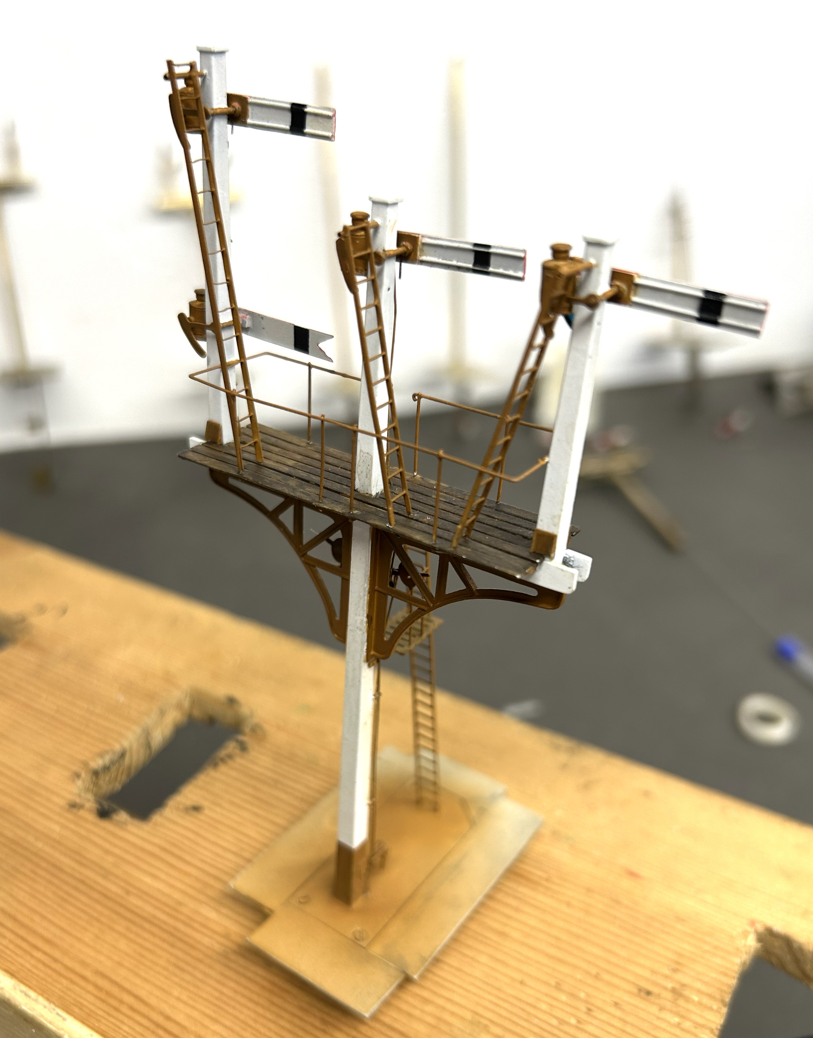
Having got the post and dolls in place, the next step was to fit the brackets.
The LNWR were unusual in not using cast brackets; instead they fabricated theirs from sheet and angle iron. Those supplied by MSE are a flat etch and therefore feel a bit one dimensional.
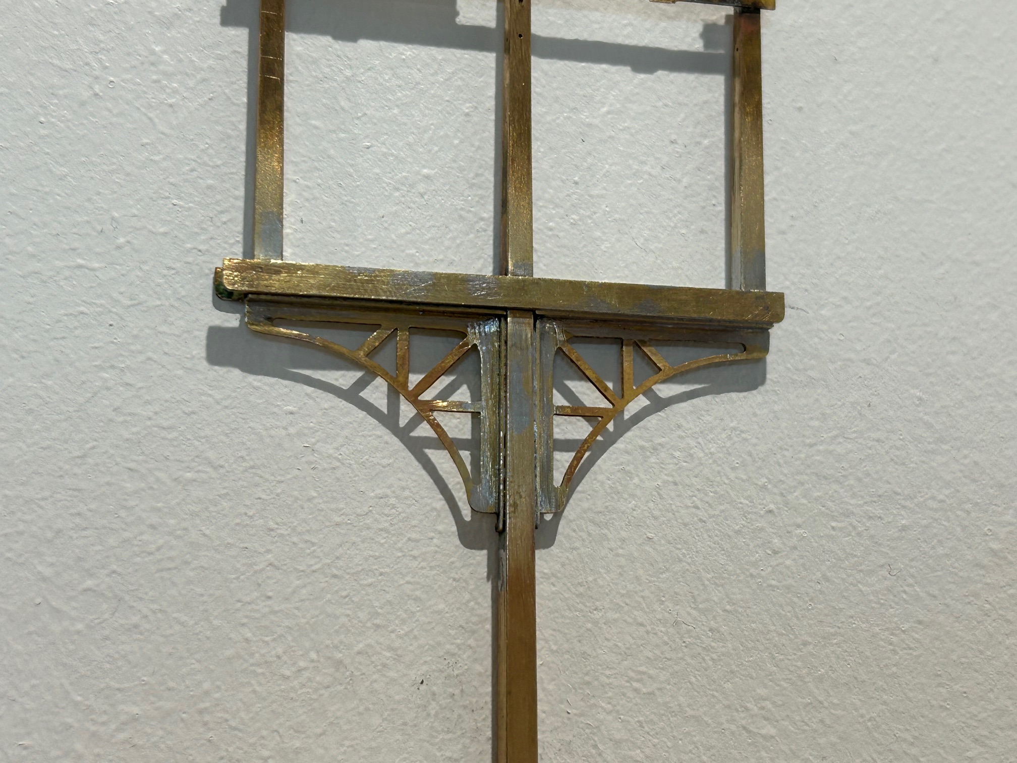
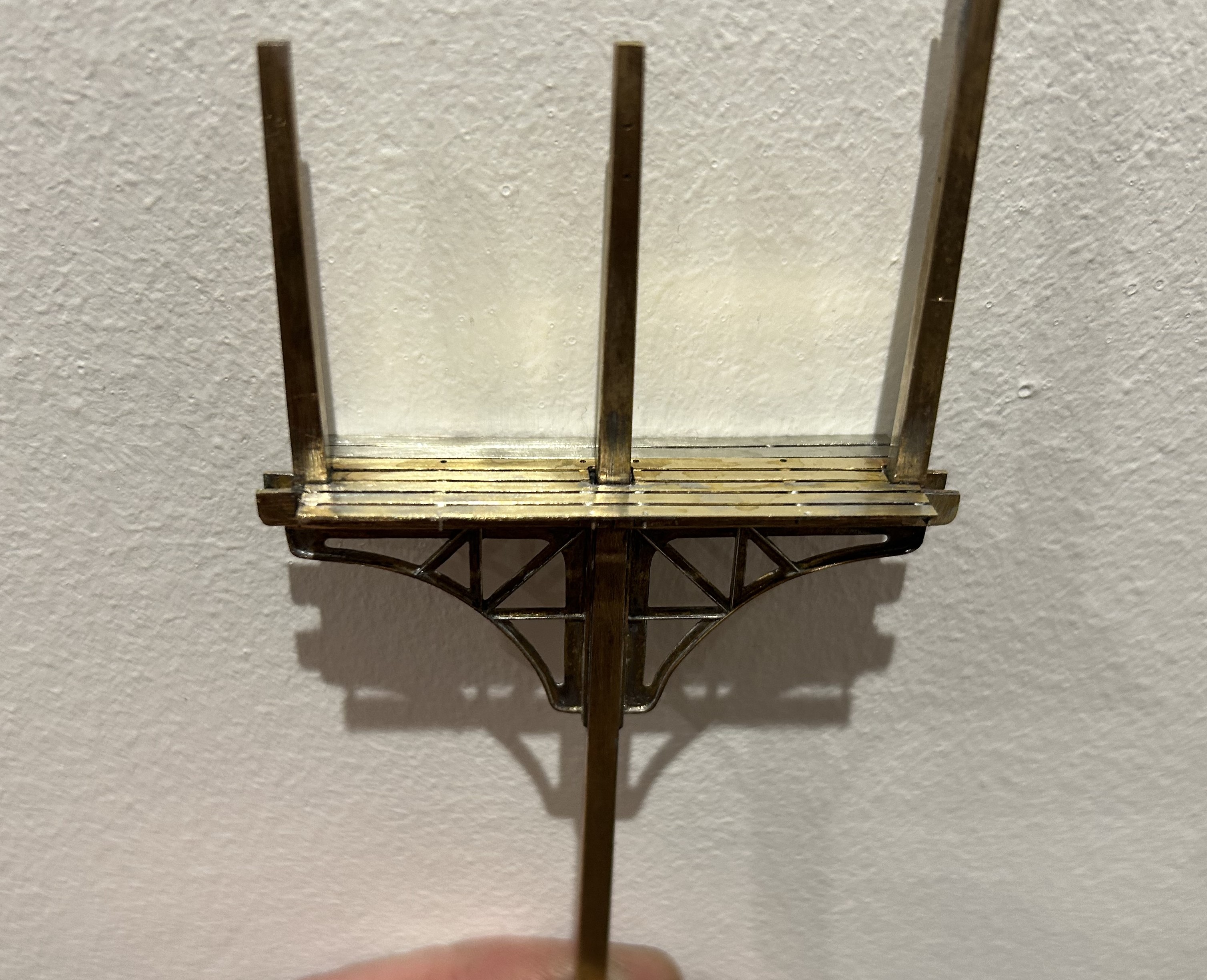
I therefore sweated on brass wire to one side of the strutts on both faces and also a plate on its outer edge. This helps give this a third dimension that was lacking before.

The next issue to be confronted was the landing where the MSE etch only provides a landing to the rear of the posts whereas this (and it appears many other LNWR signals) have landings both sides. I therefore had to produce support brackets and an enlarged area of landing. Foolishly, I forgot to drill holes for the guard rails before assembly, which meant that i had drill them in-situ. This is awkward due to the proximity of the dolls – it cost a couple of drill bits as a result and as a useful reminder to get it right next time!
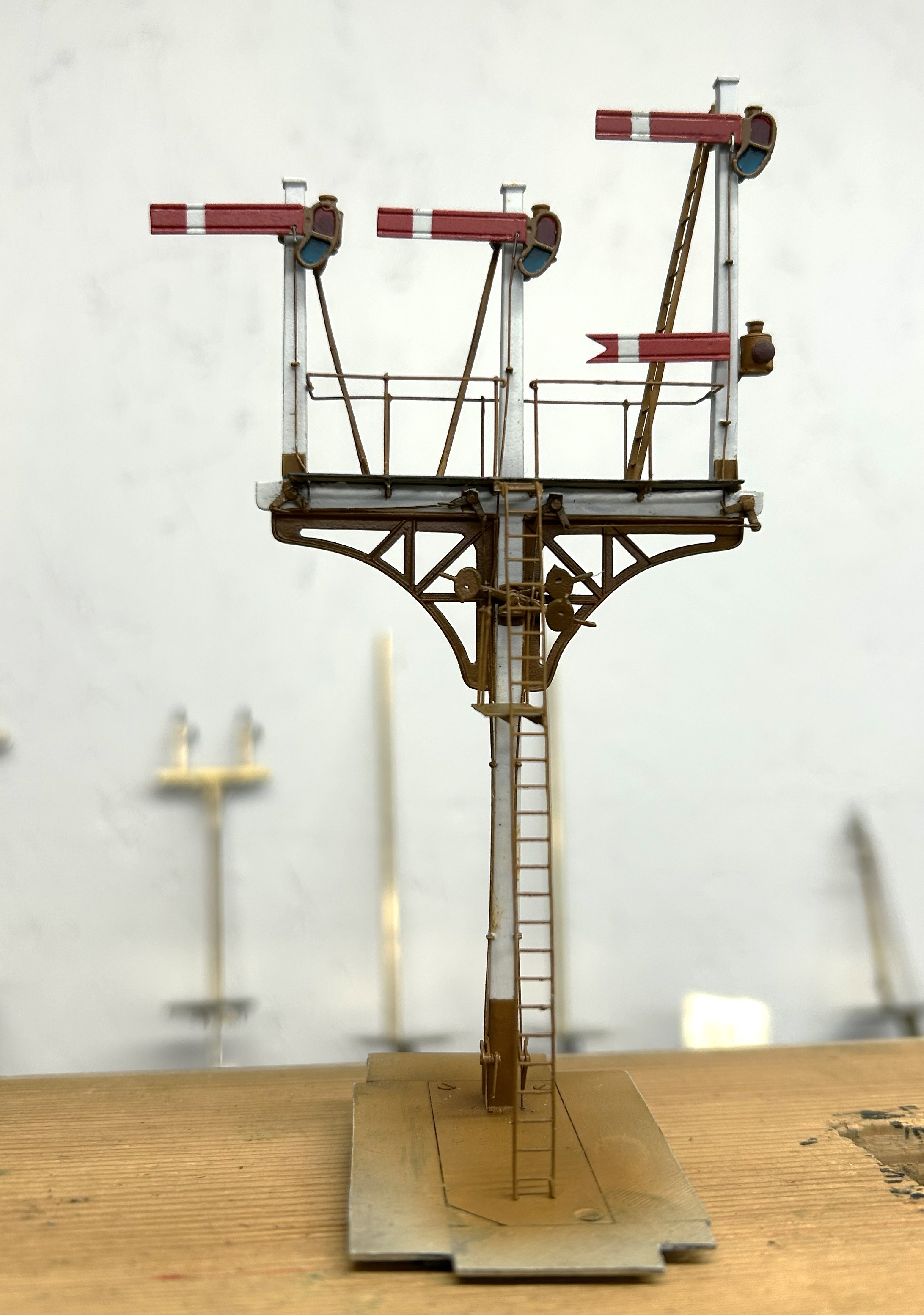
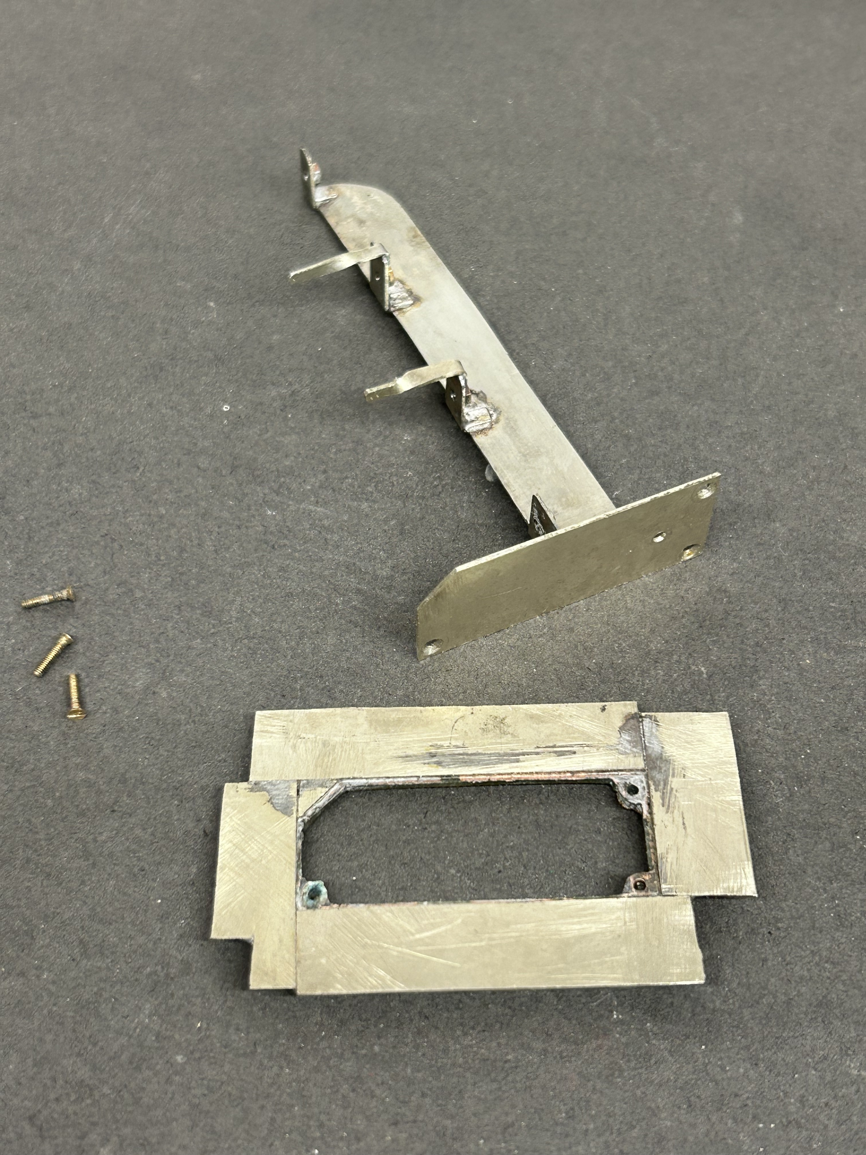
Next, I diverted my attention to the the mount for the servos. I now always form these with a lower base which is permenantly attached to the baseboard and into which a second detachable base plate is inserted. The two are a tight fit such that once a little scenary is applied to the top, the joint is invisible. These are secured together with 12BA screws to allow it to be detached both during the build and for maintenance but generally it is secured in place. This is because signals are prone to damage when being moved about and would need recommissioning to get the movement correct each time they are reinstated.
I drilled the underside of the post and tapped it 10BA in order to hold it in place. This enables me to secure it onto the base but subsequently remove it as I build it. I do solder it in place at the end of the build, but the ability to remove it during the build is helpful. The fact that the bolt holds it in place also makes it easier to get the post vertical, rather than trying to hold it vertical simultaneously with the soldering.
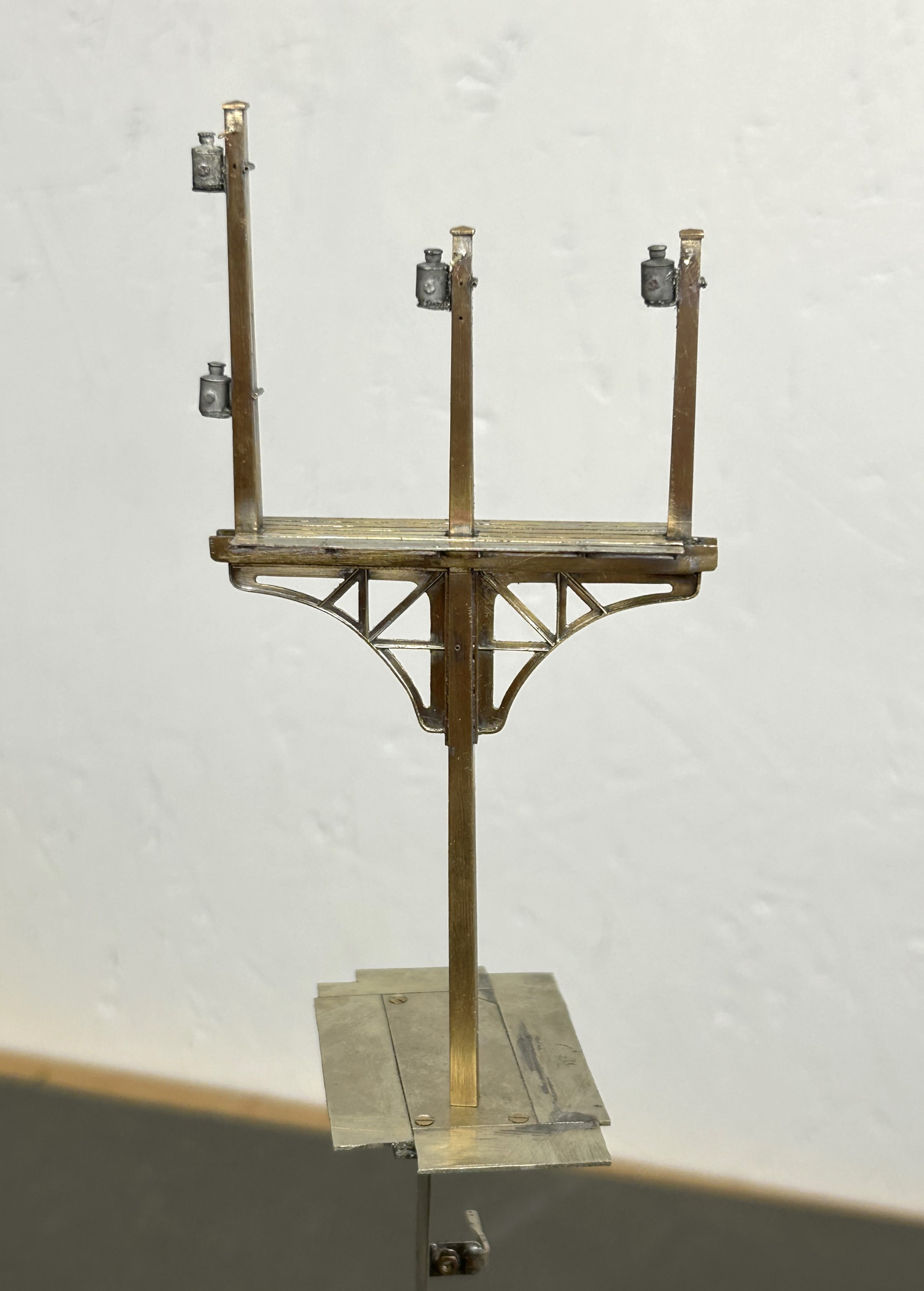
Whilst MSE do provide a white metal casting for the finials, I opted to fashion my own with brass as I find them crisper. To ensure these do not fall away as later tasks are completed, I use a high melting point solder for these and also include a pin drilled into the top of the post. Lamp brackets, lamps, the balance weight mount and some supports for the ladders were next.
I now have a recognisably signal beginning to form but the difficult bit, the movements are still to go.

Delayed Delivery – Part 2
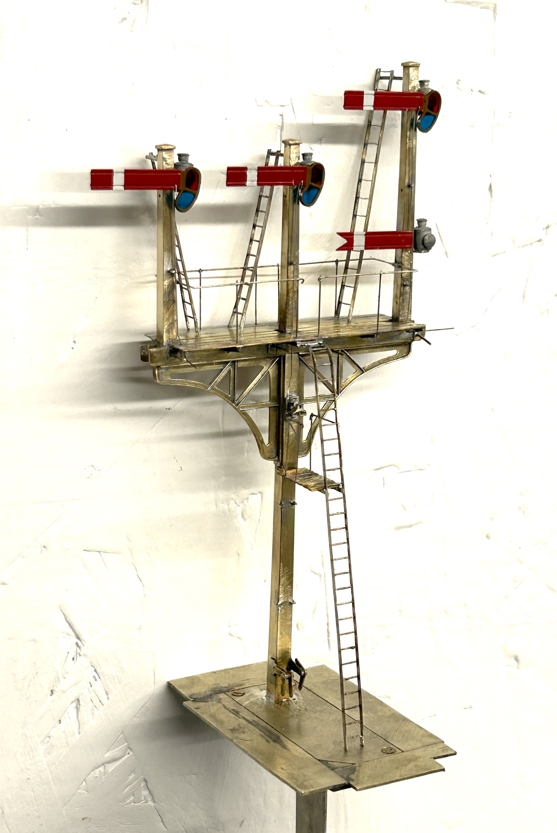
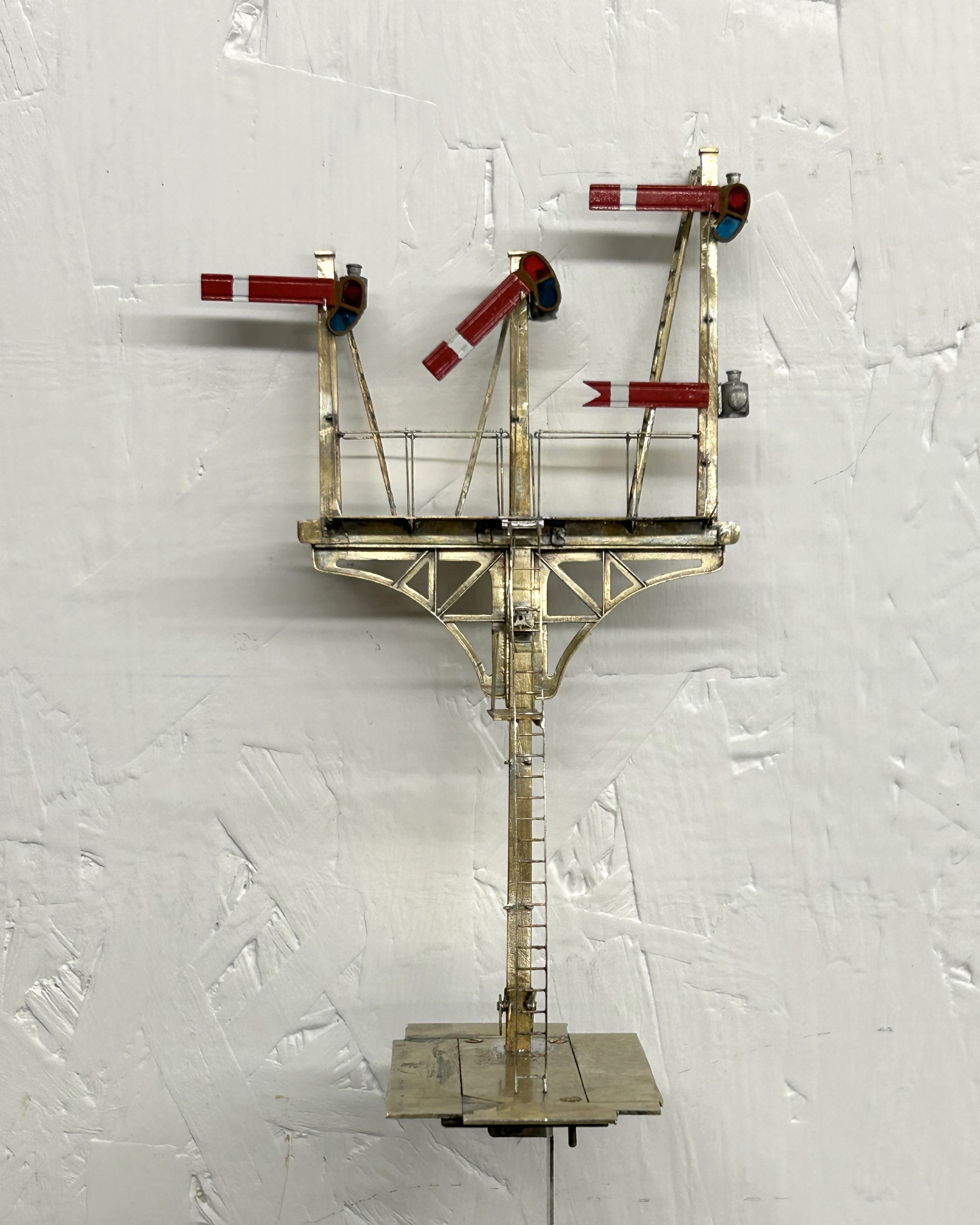
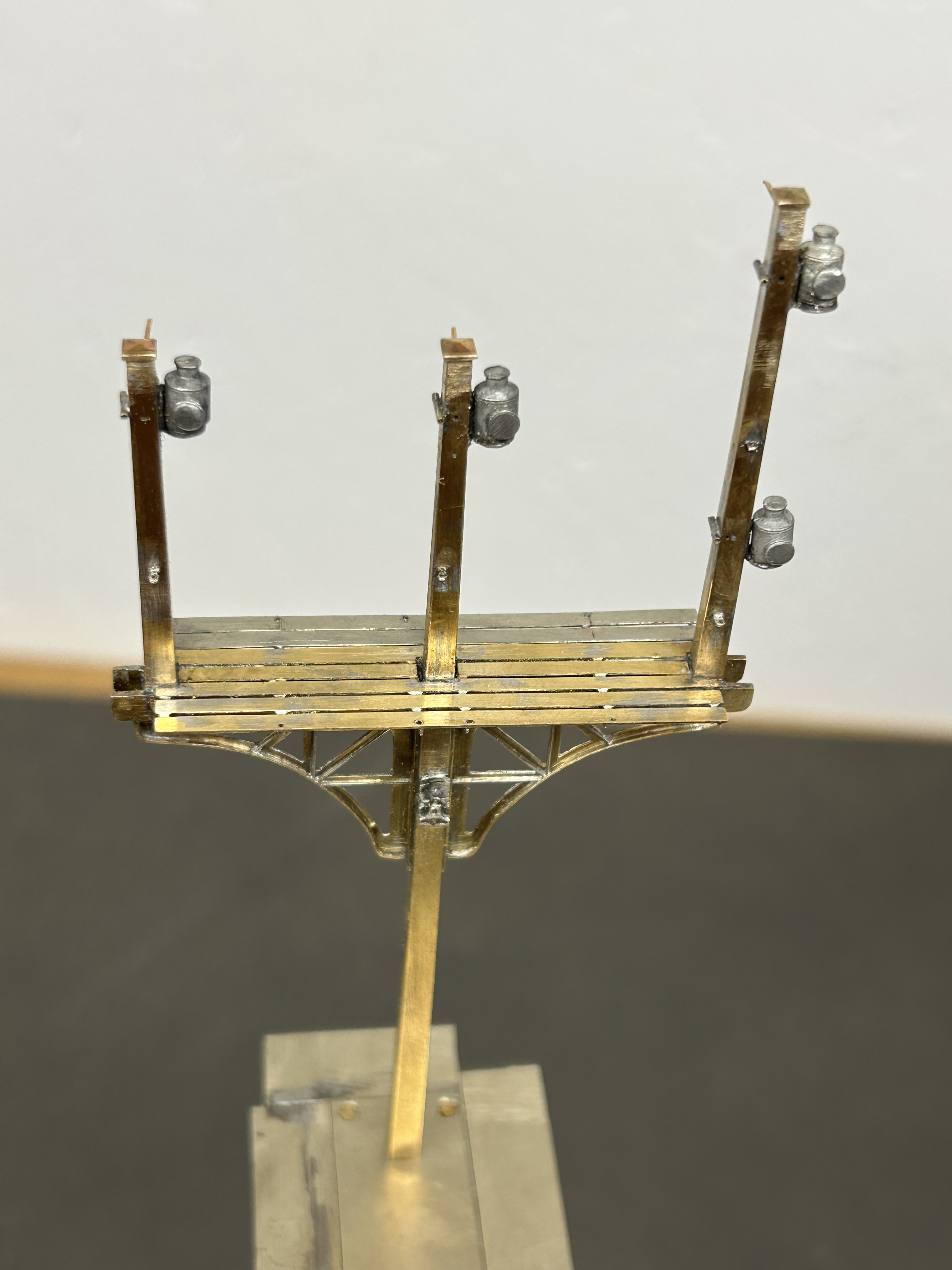
Once the basic structure of the gantry is in place, the real task of making the signals signally commences. First up were the smoke deflectors and the brackets for the balance weights. Also fitted are the main portions of the fan route indicator, but that will be explained further once I get it going!
For the arm bearing point and lamps I am using some 3D prints produced by Steve Hewitt and available from Shapeways. They can be found here https://www.shapeways.com/product/JJRSB … arketplace. They are fairly expensive but they are neat and save a lot of manufacture. There is, however, a but – they are very delicate and I am very fearful of thier long term durability. I am highly likely to draw some of my own up and get them cast in lost wax. It will make them even more expensive but I have about a 50% casualty rate at the moment, so maybe in the long term it will be cheaper!
The arms are Masokits, these are definitely the best available arms for LMS/LNER/BR semaphores. This is especially true of the minature shunt arms as the MSE ones are simply too delicate to bother with (imagine how do I know that………….!). So this is where we are now at with the arms mounted temporarly on the bearings.
There are five movements in the down direction (three of which operate via the route indicator) and then a pair in the up direction – hence the back to front arms.
The plates at the top of the dolls are mounting points for ladders. It transpires they are wrong and have already gone!
So the intensity level has dialled up a notch with these portions (especially breaking the bearing/lamp fittings) but it really gets interesting when you try and make these things work.
I don’t know myself yet (although I know for the couple of arms I have finished, so I have an inkling), but i think it might be fun to have a little sweepstake on how many moving parts there will be in the finished gantry. Five arms, three fan route indicators and each is operated by way of angle cranks. Each arm, crank and intermediate wire counts as a moving part, as do the servos………………..guesses please?

Controlling Bottom Works Sidings
Followers of this blog will probably be aware that I share some of my model railway escapades with the two authors of the blog OTCM. Both of the authors are in the process of putting together entries into a competition to build cameo layouts being orchestrated by the publishers Titfield Thunderbolt. Cameo layouts was the topic of a book written by Ian Rice and seeks to describe a small layouts seeking to use presentation techniques to capture a slice of the whole in a convincing manner.
To be fair to Oly, his entry is largely complete as long as he does not seek to tinker with it too much(!), the same could not be said for Chris’s entry – titled Bottom Works Siding – so he has some catching up to do! To assist Chris I offered to make his signals and after a few weeks of work we have reached the point where they are complete.
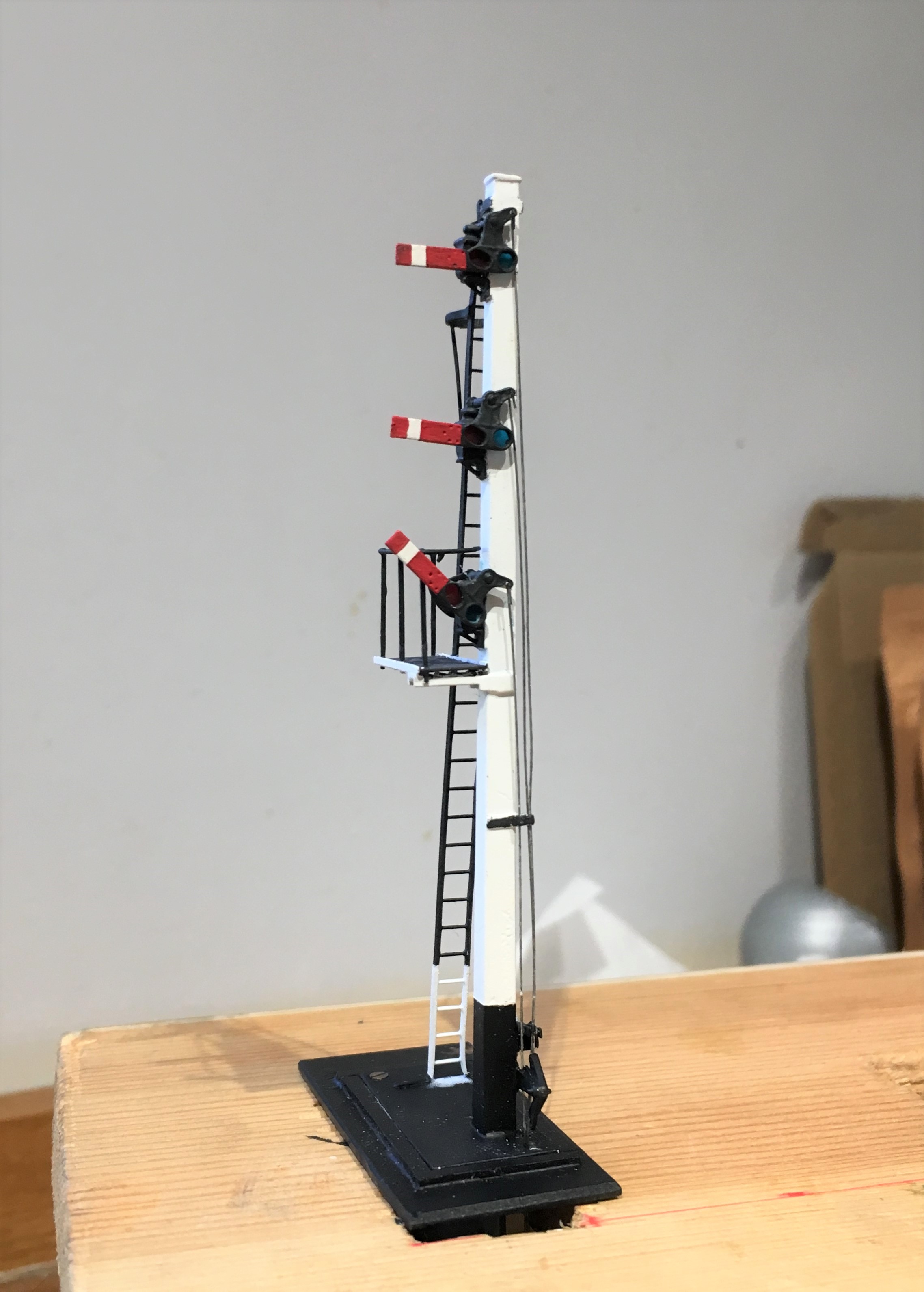
Chris’ model is based on the GCR’s route over the pennines at its Yorkshire end. It will represent a set of transfer sidings from the Woodhead route electrification to a industrial line serving a coking plant – so I suspect we will get to see a fair amount of grot in the finished article! Its signals are LNER or BR(E) practise which is mildly different to what I have built before in some regards but not others as there was a lot of standardisation between the LMS and LNER (and BR more or less adopted LMS practise). So first up (above) is an LNER standard wooden post with replacement BR miniature upper quadrant arms. The post is a piece of brass square section that I filed to a taper (hard work) with predominantly Masokit’s fittings (which I found to be notably better than MSE’s equivalent).
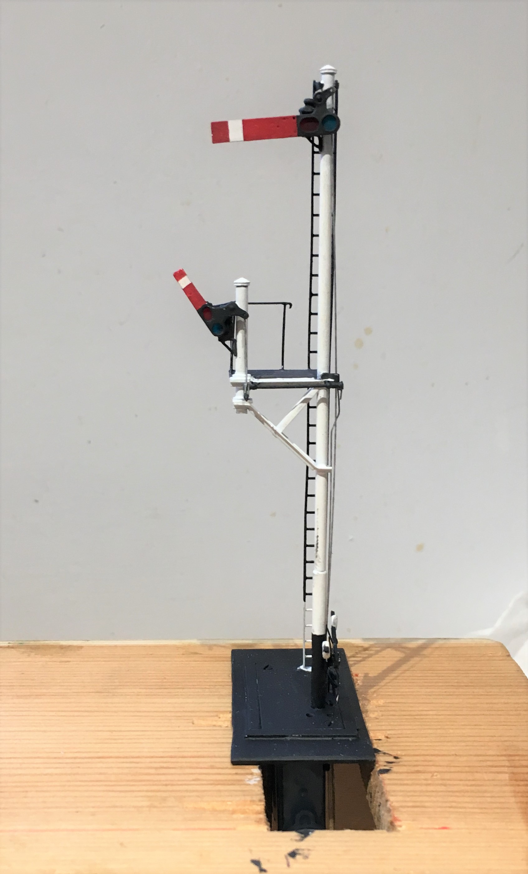
This one is effectively a standard LMS/BR tubular post signal (apparently with brewer’s droop – sorry!) with a small bracket that has another miniature arm signal to it. This is assembled with a combination of tubes and angle section from Eileen’s Emporium, along with some more Masokit’s arms.
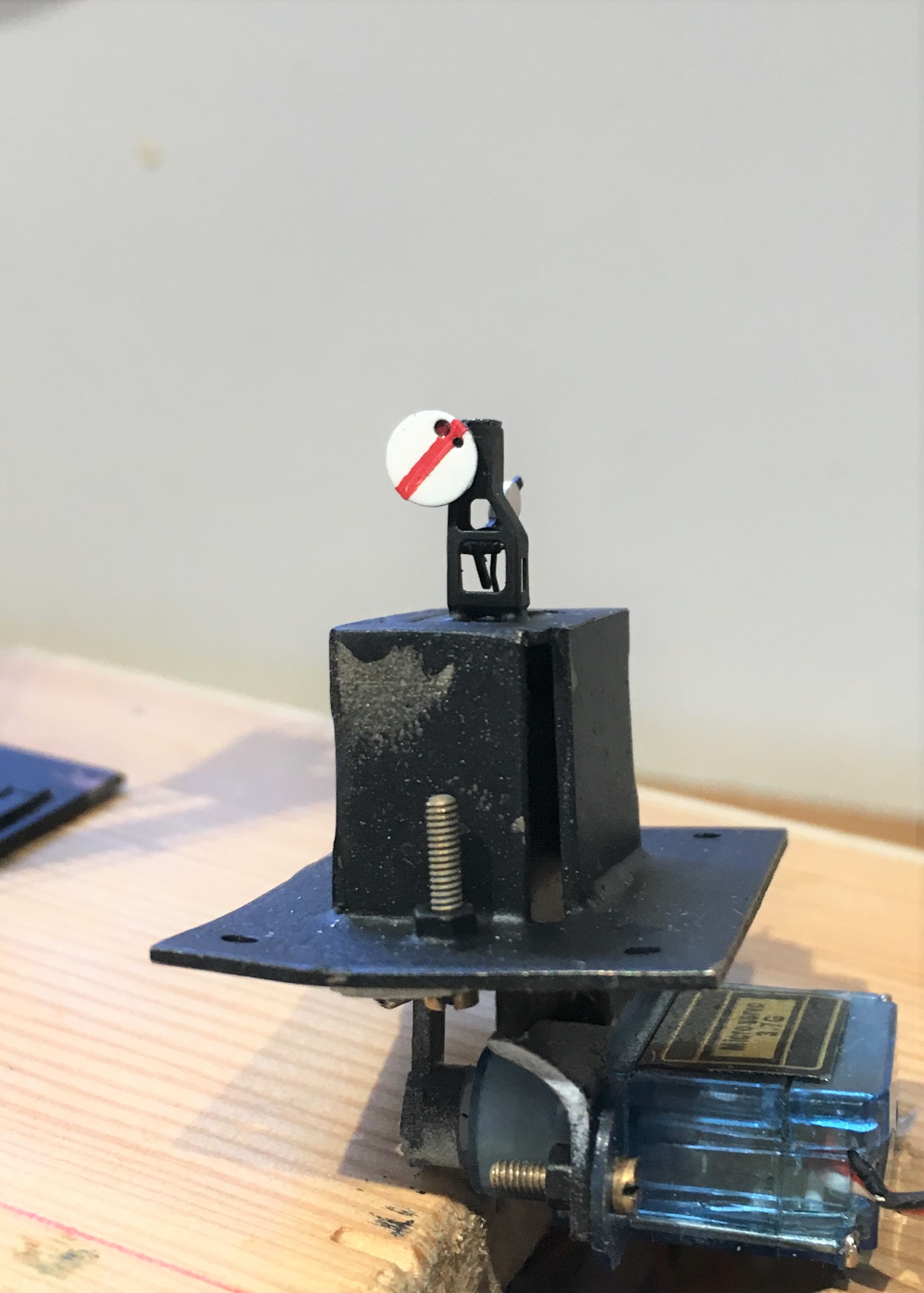
And finally a miniature ground signal – which despite being startling small was not actually all that difficult to build – it being based on a excellent little etched kit from Palatine Models.
As a result of a lost camera, there are not really any meaningful photographs of the signals being created but fear not, I still have a few to go for Glenmutchkin, so there will be some to come! In the meantime, and to prove that they really do go, here are some videos.
In the fullness of time, I dare say we will get to see these in situ, so why not subscribe to Oly and Chris’ blog, to get an instant notification?
