Scrap Tank Test Build – Part 2; Continuing with the Body
The next stages of the test build were to do the footplate/tank sides/can exterior.
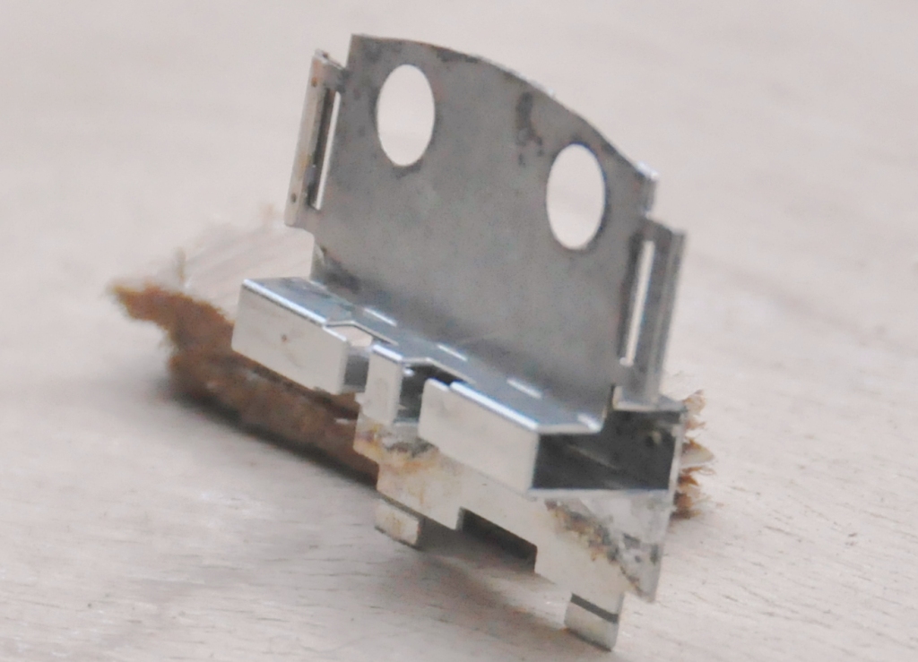
My initial design for the footplate is not particularly radical, but the test build has shown up that until the boiler is put in place (which comes some way into the build process) the front is somewhat delicate, irrespective of whether the footplate valences are fitted or not. Thus, in addition to the temporary stiffener that can be seen to the front of the footplate in the picture below, stiffeners will be provided to the front half of the footplates. The idea of these can be seen in the following view which shows the rear of the cab. By folding these over at 90o during the build, they give strength to the more delicate parts of components. Some will be incorporated into the finished article, others will simply be discarded when their job is done.
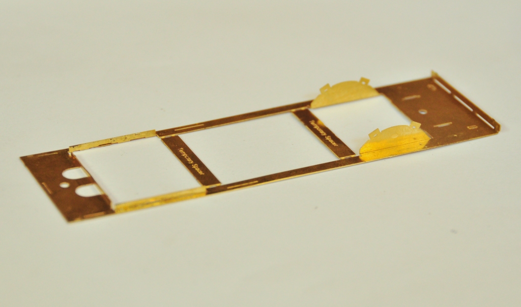
The two tanks, along with the sides to the cab/bunker, are conceived as a single piece (if you go back to my previous posting, you can see this in the flat in the etch). The two halves are separated by temporary spacers to both assist in locating them but also to give strength to the assembly prior to the fitting of the boiler which is where it will get its strength from. It was when I tackled this part, I reached the first disaster – the etchers had failed to half etch from behind so I was missing some fold lines. This was pretty frustrating as it entirely negated the intended efficiency of the design and even though I now have a corrected etch, I had to solder on by cutting the parts at the intended line of the half etch and soldering them together in the more traditional manner – exactly what my design was intended to avoid. As a result of this, there are no neat photos of the tanks being folded up and secured in place, we have to jump on a bit to see this.
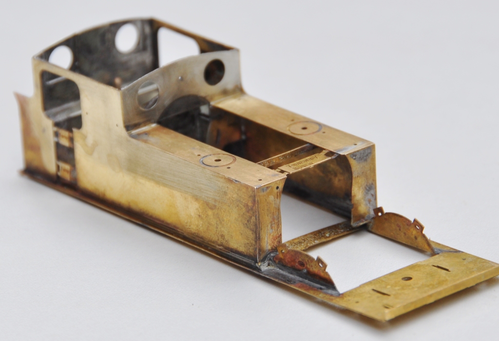
The cab fronts that were constructed earlier were no slid into place and I was pleased to find that it all fitted very snugly and in exactly the correct location. I did find that I could put in a further pair of fold up tabs on the running plate that meant that it was essentially impossible to put this in the wrong location, so this is another little refinement that will make its way into the production batch.
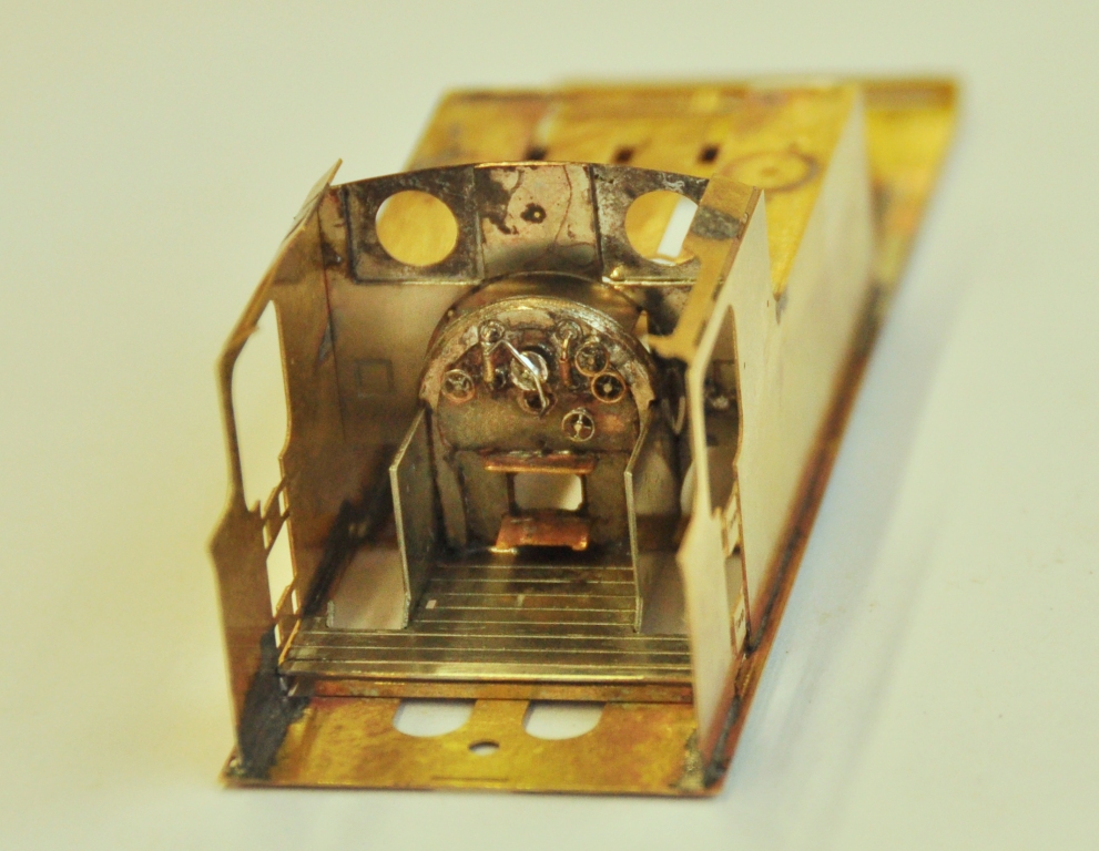
The rear of the cab was a similar fold up unit to that to the front, which was pretty easy to build but did have one dimensional error at its base that needed cutting away – well that is the purpose of a test build! All of this, has been created from one piece in maybe three minutes!
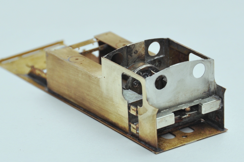
And this is what it looks like with the cab rear in place. If you look carefully, a couple of 12 BA screws are just visible in the cut out to the rear of the cab – the purpose of these will become apparent in a future posting but it is another one of my little ideas to make this easier to build/better when built.
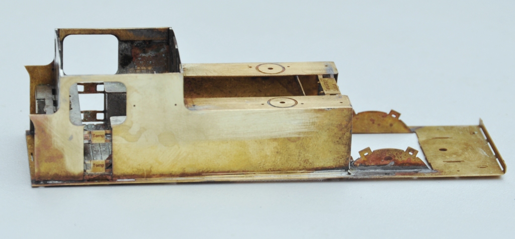
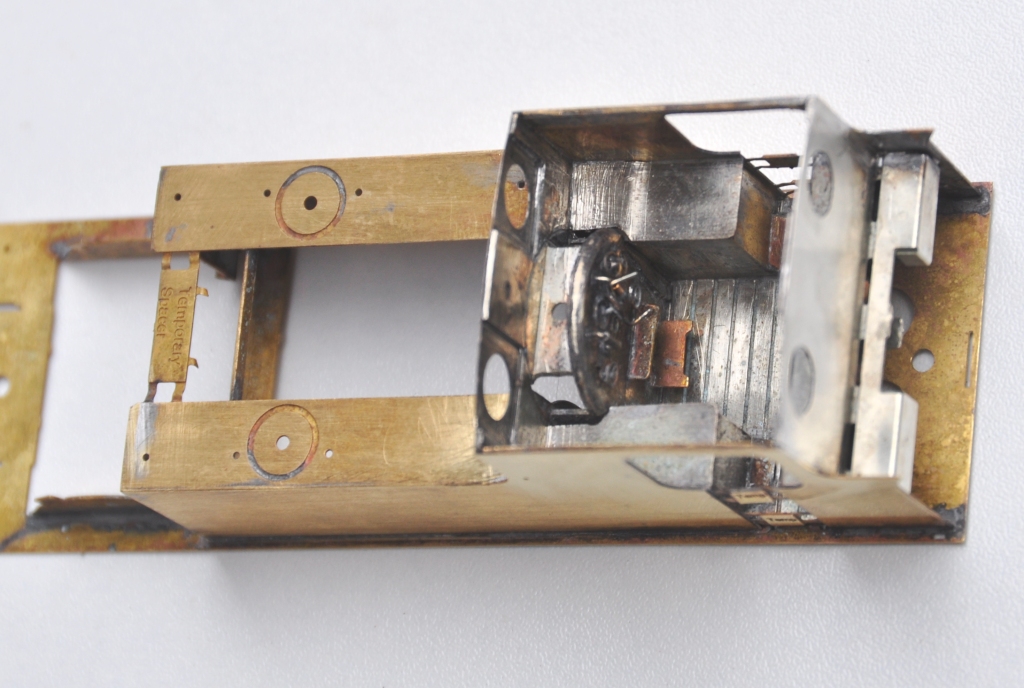
And this is what the cab bow looks like from above, after the addition of the splasher tops and backs. One of the issues this illustrates is that this kit, as it stands, will only work for EM or P4 modellers. There is insufficient room to get the narrower gauge/wider wheel treads into the splashers.
Next up will be the cab roof………….
Posted on March 22, 2015, in Workbench (stock) and tagged Design, EM, etching, Highland Railway, Model Railway, p4, Peter Drummond, Scrap Tank. Bookmark the permalink. 2 Comments.

Mark, great to see how this is coming along, I have always liked the Scrap Tanks ( i think your description of “Brutish” is spot on). Neat design touches on multiple folds and I like the temporary spacers (should help with what I always feel like the need for 4 pairs of hands to build brass!)
I will be ordering!!
Thanks Darren, I have a fair few things to iron out before I will sell it on, but it is certainly my intention to do so.
Mark