Scrap Tank Test Build 5 – Getting on with the Chassis
With the basic chassis made, it is essential to fit the nuts to secure the body to the chassis as both of these will be concealed with later work. So a quick test fit looks like this and we can get onto the next bit, the coupling rods. 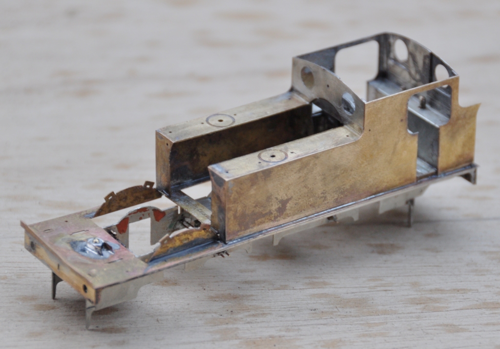
As is not uncommon, these are made from a pair of layers of brass laminated together. You can see that the outer layer is half etched for much of its length, with the full depth only being present at the bosses. I have also sought to make it easier to build these by including them in a folding jig – the folding is underway in the bottom portion of the view. The logic of the jig, indeed the whole kit, is to make a really smoothly running chassis much easier to make. Modern CAD and computer operated phototool creation techniques by the etchers means that it is possible to easily draw and then etch such that each dimension is faithfully repeated on the product. Thus, it is possible to be confident that the wheelbase will be repeated exactly on each side of the frames and also on the coupling rods. However, this accuracy is completely lost if the user has to laminate the two parts together by hand; it is not possible to get them superimposed on each other exactly or repetitively so the spacings of the crankpin holes will change. The jig overcomes this as the fold line is so long that there can not be any twist as it folds, so the two parts will meet consistently and accurately. 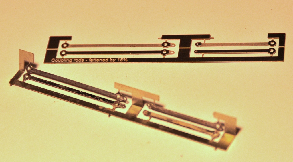
It is true that there remain two areas of variability. The first is that the degree of etching will not be exact on every occasion so the holes will be slightly bigger or smaller on each occasion. This can be easily overcome by making all critical holes a tiny bit too small and then opening the holes up with a ream (not a file, reams will open up a hole consistently). The second problem is that a fold is not always consistent on a fold line so the jig can protect against twisting but might not necessarily put the two laminates directly on top of each other. However, the important point is is that they will be correct horizontally, any error can only crop up vertically. Thus, when the crankpin whole is opened up, it is possible that it will move vertically slightly but this will not change the dimension between the holes so the critical dimensions should be retained perfectly.
The above is all true in theory but in practise there was an almighty cock up in my artwork; so I was deprived of finding out. A total case of designer error and when this is yourself, there is no one else to blame………………. 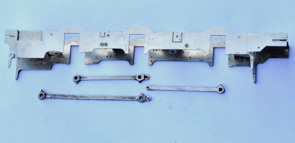
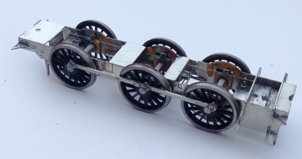
………..I made one of the coupling rods no less than 8mm too long – doh! I have no idea how, but it needed chopping; so it was back to the old fashioned way of making coupling rods despite my high ideals! Fortunately, as they were laminated, it is possible to stagger the cut to make the splice – essentially the same technique as Alan Gibson’s variable length coupling rods. Anyway, after the cutting and splicing, I did get a sweetly running chassis and this is what it looks like. The unusually large wheels for a shunting loco are already making their presence felt! 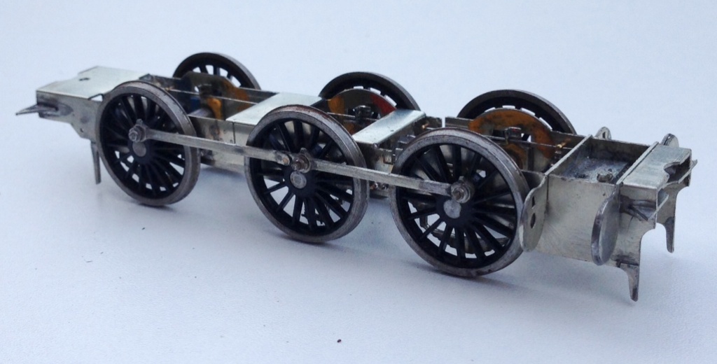
The chassis is created around CSB’s; continuous springy beams. A spring wire is anchored to the chassis at four points per side (for an 0-6-0) and at the centre of each hornblock. Thus each hornblock is supported on either side and can “bounce” on the spring. However, the clever thing about CSBs is that when a hornblock is depressed, not only does the spring wire flex a bit as suspension, but it also rocks on the anchors so the adjacent wheels push downwards a bit to equalise out some of the deflection. It produces a really smooth chassis and, if it is conceived at the design stage, I think is actually rather easier to both design and build than traditional compensation. This is a close up of a pair of hornblocks and a pair of the anchor points (the other is hiding behind the frame spacer on the right). Also worthy of note is the colour coding of the hornblocks; to enable them to be reinstated in the same hornguide each time. This is probably unnecessary with modern (and therefore consistent) hornblocks and the accuracy of the etching I have noted but old habits die hard! 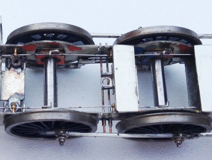
Posted on April 12, 2015, in Miscellany Models, Workbench (stock) and tagged EM, etching, highland, Highland Railway, Miscellany Models, Model Railway, p4, Peter Drummond, Scrap Tank. Bookmark the permalink. 1 Comment.

Reblogged this on sed30's Blog and commented:
Good construction tips