2P or not 2P, that is the question
How often do we look to start a project as it will be relatively simple to do before we tackle something more challenging but then find it wasn’t quite as simple as we thought? Well, for me this seems to be a recurring theme and this is one such example; albeit one that is largely self inflicted!
I wanted a fairly simple loco to have finished quickly and I thought the Hornby 2P would make a simple wheel swap conversion. And so it would be if I could accept a few compromises – my problem was that once I started it, I came to the conclusion that I couldn’t.
The first problem is that whilst the loco body had an upgrade within the last decade or so, the tender was not only from the last millenium, but not even near the end of it! It is very crude and the thickness of the parts suggests that it was made from left over armour plating from a Dreadnought. It had to go, but that story will be for a future blog post. Instead, we move to the second problem – having decided I could tolerate the narrow frames and crude bogie, I changed my mind. To be fair to myself, I blame Rumney Models for introducing some rather nice LMS loco bogies and I could not very well fit one without also attending to the wider chassis. So, an order went in to Comet for their chassis and my simple quick project ceased to be!
Of course, I then decided to make it a tad more difficult for myself by deciding to include CSB suspension. Actually, I don’t agree with that (admittedly regular) accusation as I find that once it is set up properly – which with the High Level jig, CSB chassis are quite easy. So once this was set up it was time to set up the chassis – I did this by initially laminating the two faces of the coupling rods together “in the usual manner” but I deliberatly used a high melt solder. This enabled me to also then solder the two coupling rods to each other with a lower grade of solder without the fear that the laminate would come unstuck later. This was done prior to the opening out of the crankpin holes – which i did on the piller drill so they were formed as a perfect pair. This is then where we got to:
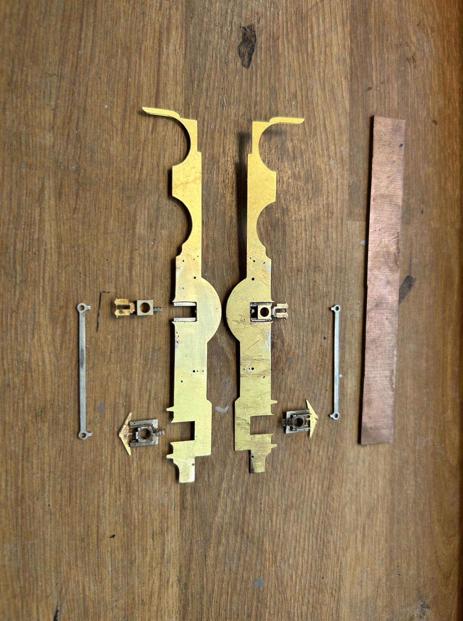
You will see that I have used High Level hornblocks but have attached the cosmetic springs to them. Not my idea but a really neat solution to acheive one of my key expectations of a chassis which is that the wheels are capable of being removed. I do this so that I can get the wheels in and the chassis operational at an early stage but can then remove them later whilst the the remaining detail is added without flux leaking onto the steel components or damaging the wheels. It also has the advantage that they can be removed for painting and future maintenance.
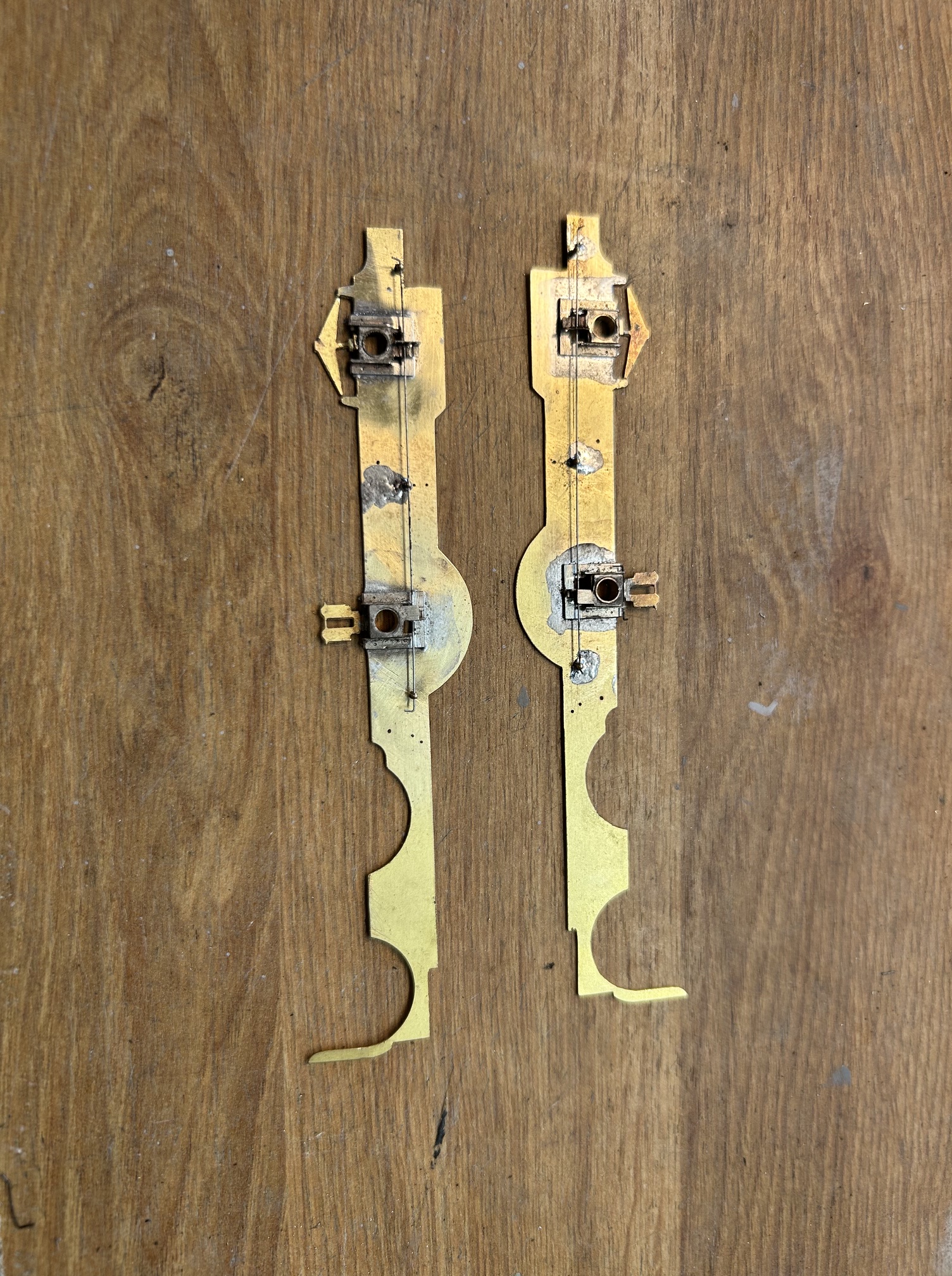
CSB stands for “continous springy beams” and these can be seen in the above image as the wire that it spanning from anchor posts on the frames and across a tag on the top of the pair of hornblocks. They act about half way between compensation – because as one side is defelected, it pushes up on the other side – and also springing because the wire also gives a little. Once set up, they are very effective and if you decide that the height is not quite right, the tags can be adjusted to raise or lower the height of the axlebox and the wire thickness can be changed to make them softer or harder to suit.
The axlebox spacings was achieved by way of the use of a chassis jig which I will do a post on in the future, as it is well worth understanding. Having set out the axleboxes, the two frames could be assembled (again using the chassis jig to ensure the axles are perpendicular to the frames. We now have the basics of the chassis made.
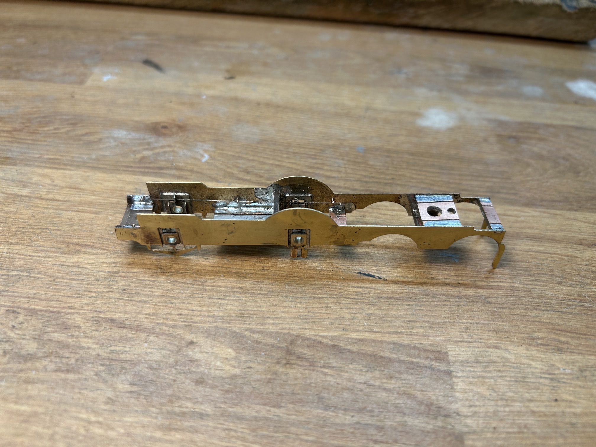
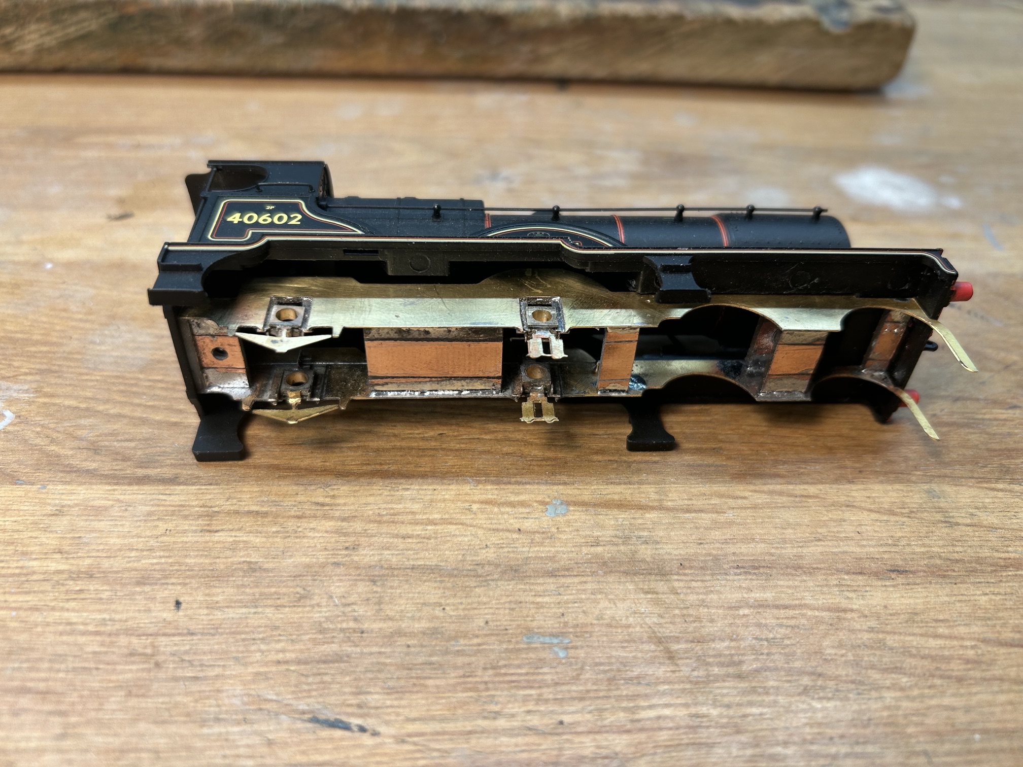
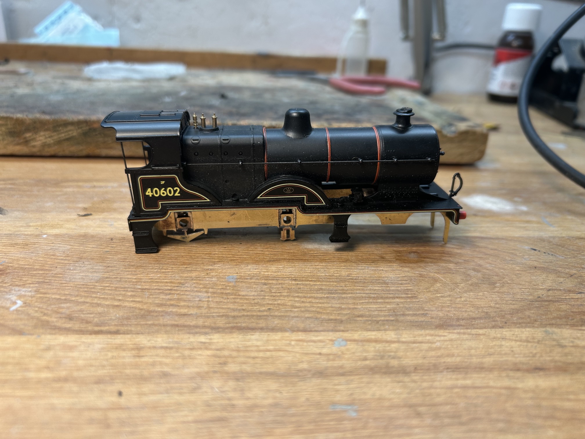
And now, by adding some mounting points that matched the screw holes in the Hornby body, it could be fitted in place and at last it is beginning to look a little like a locomotive (admittedly only a very little…….).
Next comes the wheels and following comments on the Scalefour Society forum, I have modified my technique for doing these. This is intended to get the wheels on the axles more squarely. What is not immediately obvious until you look is that the hubs of wheels project beyond the rims of the wheels, as can be seen below:
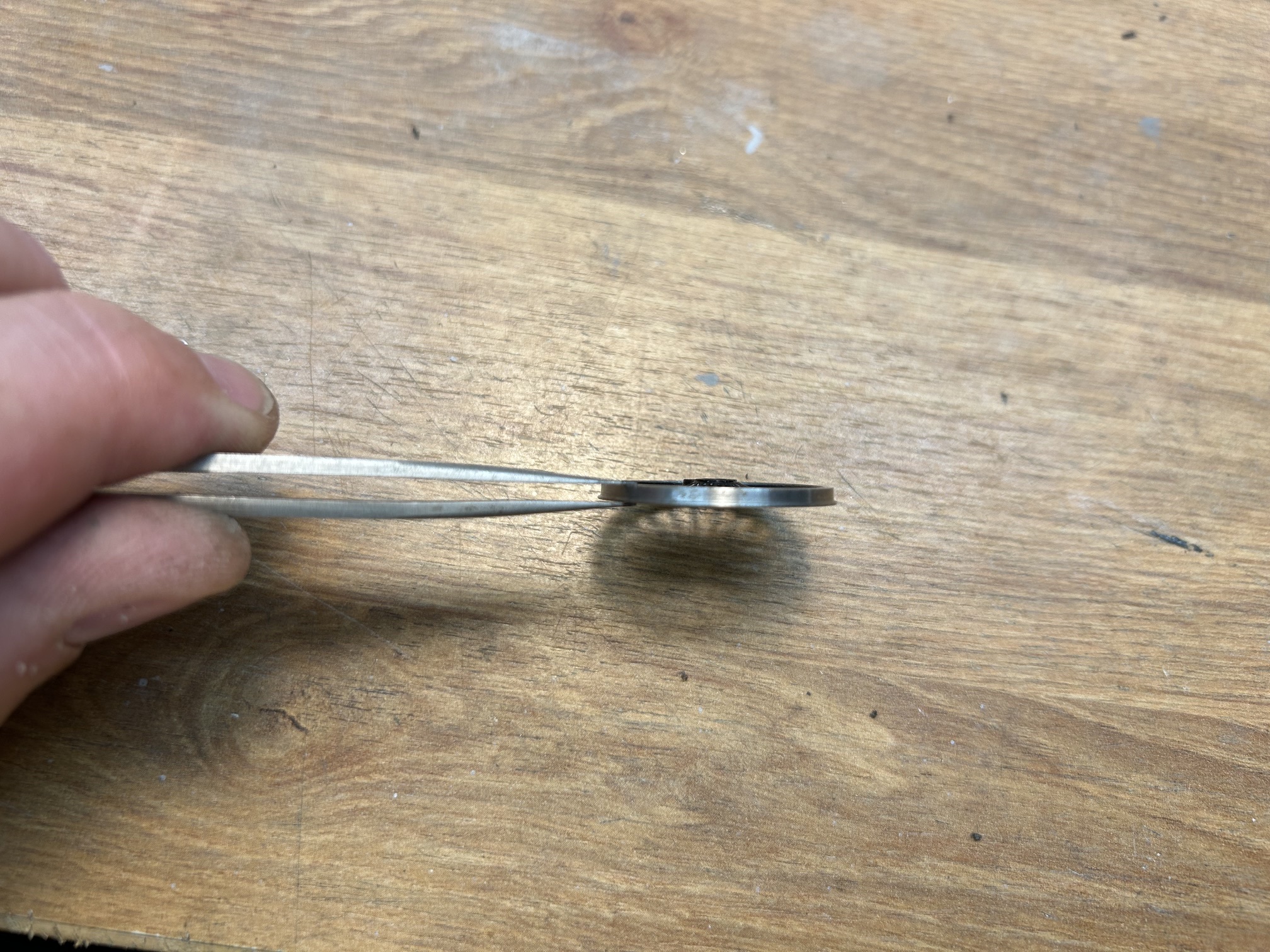
This means that the wheel press is actually only pushing on a small part of the wheel and more than that, one close to the axle. With large diameter axles in particular, even a small error here gives a significant change of gauge which can lead to derailments and also a waddling of the loco as it travels down the track. The trick alluded to on the forum was to adjust the wheel press so that it presses on the rim of the wheel by attaching a shim of plasticard.
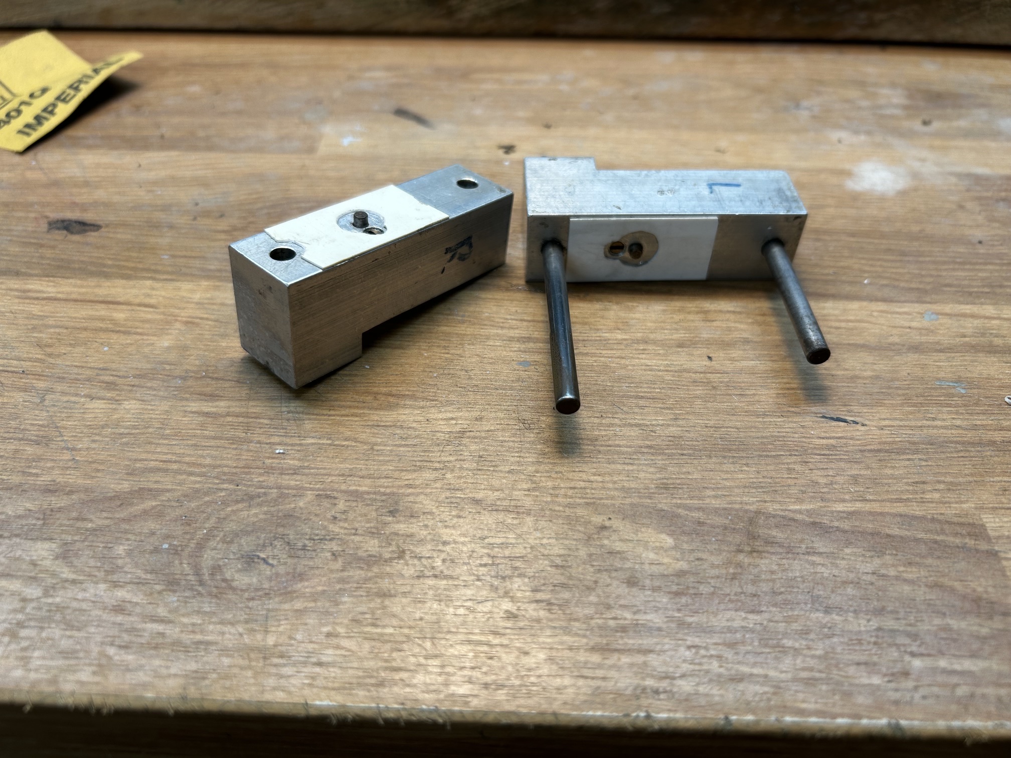
I am really pleased with the impact that this simple change has had, the wheels are on much more squarely despite being the largest drivers I have fitted.
Fitting the motor, with a High Level gearbox, got me to a working chassis. I am particularly pleased with this one as it is so smooth.
However, having got to a neat working chassis, I obviously had to unpick some of the work that I had made, as I will allude to in the next post.

Posted on August 31, 2026, in Workbench (stock) and tagged 2P, Chassis, Comet Models, Etched Brass, Fowler, High Level, hornby, Kitbuilding, LMS, Loco Building, Locomotive, Model Railway, p4, Rumney Models. Bookmark the permalink. Leave a comment.


Leave a comment
Comments 0