
Gresley Buffet – Part 4 Finished!
…..but, before it was counted as finished, it needs to be doing the job it was designed for – buffeting. And that means it needs to be populated with people.
Regrettably few modellers, even finescale modellers, actually put people in thier coaches (and sometimes in contrast to platforms which are stuffed with them!). This is a shame as they do make a difference to even a fairly casual viewer. At a show recently, a dad and his son who were probably not modellers spotted the people in my coaches instantly. I’ll take that as proof of the point!

As is common with rtr coaches, the seats are moulded in place such that there is no room for the little peoples legs, so some severe amupation is required! In the case of Hornby’s buffet, the seats are also modelled pushed tightly underneath the tables – which has meant that the backs to the seats or the lip of the table also needs to be hacked away a bit. As all of this surgery occurs below the waistline of the coach, it is not visible from outside so your Dr Crippins’ tendancies will go unnoticed!!
Next up was to paint the exterior where the new plastic was cut in and here I had some problems. I was warned by Brian of Shawplan that I should paint the whole side when I repainted the new sections but I decided not to follow this advice – something I now regret!! So having masked up theadjacent areas and sprayed in only the affected sections i found that the grey that Hornby used was notably bluer than that provided by Precision Paints. The first attempt at repainting had the colours sticking out like a sore thumb and even on the second attempt, with a dab of blue in the mix is not perfect but is just ok underneath the grime. So, if you are proposing to do follow this build follow Brian’s advice, not mine!
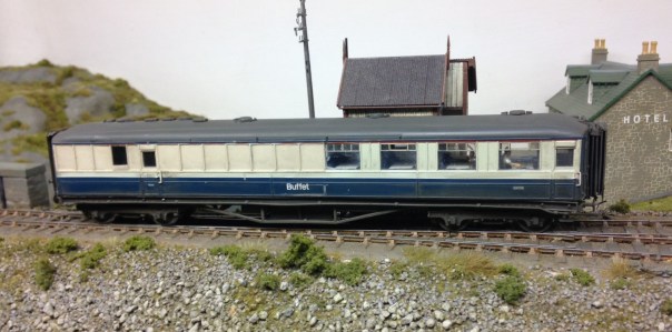
Once a couple of new windows were cut into the reshaped windows in the kitchen area of the buffet car, it was necessary to weather the vehicle. These buffet cars were notorious for being really tatty by the 1970’s; partly because the paint supposedly was prone to debonding from the underlying teak but also because the automatic washers were not good at getting into the corners of the panelling. After an overall spray of dirt to tone down the colours and another to represent the brake dust and track muck, I used two techniques to represent the weathering on the panelling. The first was to spray the whole coach with a mist and once it had started to dry a stiff artist’s brush was dipped in thinners was used to remove the bulk of the paint. The areas that it does not come away from are the nooks and crannies around the panelling; the same areas that would have retained the dirt in the real things. I to find, however, that the margine between where the paint has been removed and not can be a bit stark, so I used a second technique to both hramonise this and also acceptuate the effect. Using a heavily thinned dirty black paint, run a brush over the whole of the sides – the paint runs to the corners and achieves the same effect. It pays to be brave with this as the wetting effect of the thinners makes this initially look much darker until the thinners have dried off.
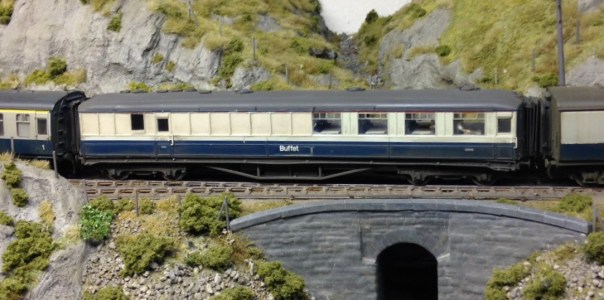
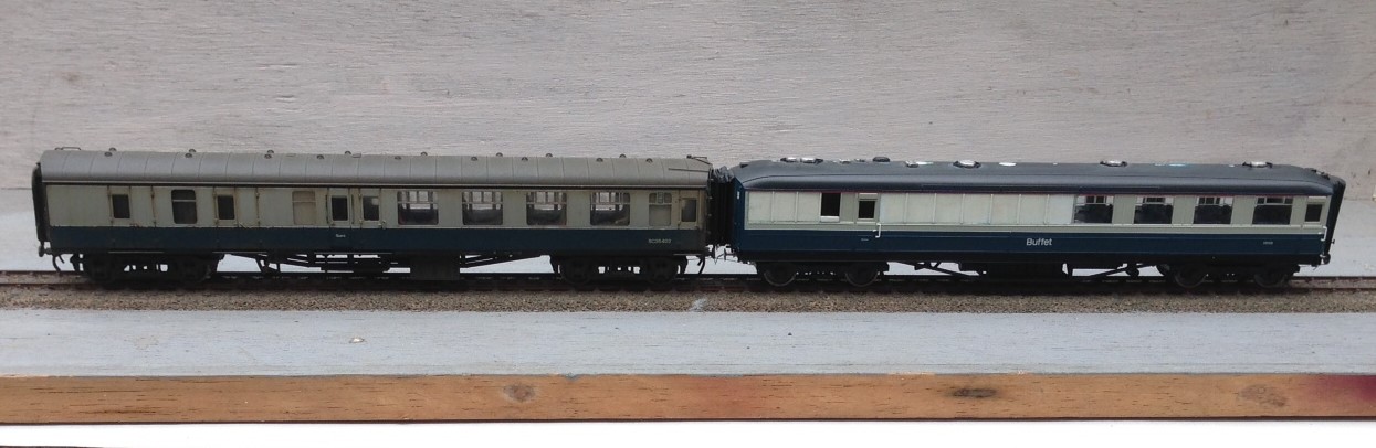
And this is what the finished article looks like………
So thanks Hornby for supplying the model in the first place and the inspiration to do some plastic surgery. Whilst this write up may have lasted some months, actually this was quite a quick conversion – the basic surgery on the side was only 4 hours – so why not have a go?
The Dingwall & Skye Railway
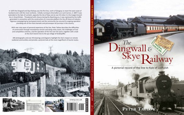
The Dingwall & Skye Railway – A Pictorial Record of the line to Kyle of Lochalsh.
For those of you that are aware of my main exhibition layout you will be aware that it is based very firmly on the Dingwall & Skye Railway, which is the name of the line we now call either the Kyle line or occassionally the line to Skye.
I have to confess that the layout is heavily influenced by my memories of family holidays to the line in the early 1970s – we were dragged up there by my father and I at least (it all appears to be lost on my brother!) picked up a bug for the railways west of Inverness. This bug seemed to have been passed to me by my father and he was in turn infected in the late 1950s when he first made his visits to the area.
Based on his love of the line to Kyle of Lochalsh, my father’s latest book is upon the line. It does not seek to be a strict history of the line (Rails to Kyle of Lochalsh does this) but is instead a review of the line on a station by station basis. It is full of photographs (literally hundreds of them) and also a substantial number of drawings of the engineering and architectural infrastructure apparent on the line as well as around it. This covers station buildings, water tanks, bridges, sheds, signals, water columns, water tanks, cattle docks and indeed many other aspects of the line. There are historical reviews of aspects of the operation of the line, the exploration of alternative schemes that did not come to pass and some of the quirky storys of the past.
It is thus for those that like a coffee table picture book, a historical review of the highland railway, those that are interesting in modelling tbe line and those that simply are caught up in the nostalgia of the “line to Skye”…..
The Dingwall & Skye Railway – a pictorial record of the line to Kyle of Lochalsh, by Peter Tatlow ISBN 978 1906 537463 @ £27.95 by Crecy Publishing Ltd. For those of you who are members of the Highland Railway Society, you will find that your membership entitles you to a significant discount if you buy from the society. Thus if you are waivering about joining the society, you will be do well to do so if only to buy this book!
Buckingham Central – Plan
In support of my earlier post on the visit to Buckingham, and in response to Michael, here is the trackplan for Buckingham.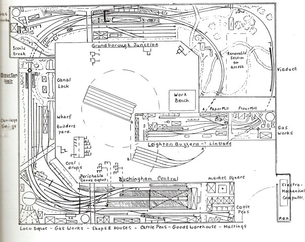
Tony tells me that there have been a couple of slight changes to this plan, but these are fairly cosmetic.
At the time of my visit, Leighton Buzzard was not set up, hence there being no pictures!
A Quiet Day at Portchullin…………
Although it may be that there is a train in the yard as the shunt signal is off…… I suspect it will be one of the class 24s?
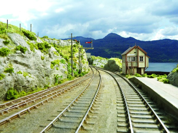
Portchullin is just back from a trip to the St Alban’s show and its next outing will be in Telford, for the Diesel & Electric Show on the 20-21 February.
With thanks to David Brandredth and Tim Venton for the cracking photo. Now my fav of the layout!

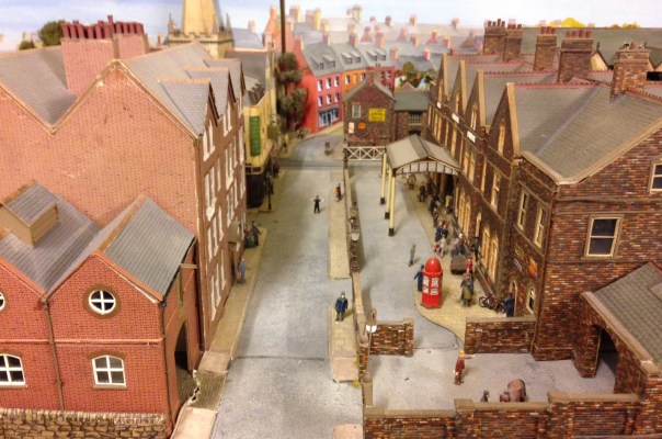
Buckingham Central
As we had to travel to Nottingham today to return my son to uni, we took the opportunity of accepting a fairly long standing offer to see Peter Denny’s Buckingham branch which now resides with Tony Gee.
Most of you will, I suspect, be aware that Buckingham was about the first EM gauge layout ever constructed (apparently, there was one other at about the same time) and can thus be said to be pretty much the daddy of the finescale model railway.
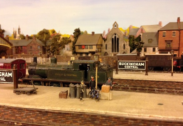
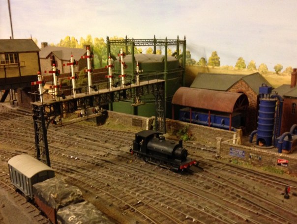
The layout has origins that go back as far as 1947, so is approaching 70 years old. There are a number of elements that go back to this era still on the layout, including the tank loco shown above which was built from the very earliest of plastics; I hope I look as good as that when I hit 70!
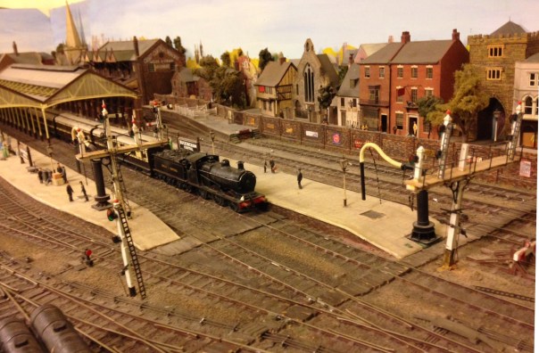
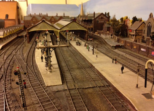
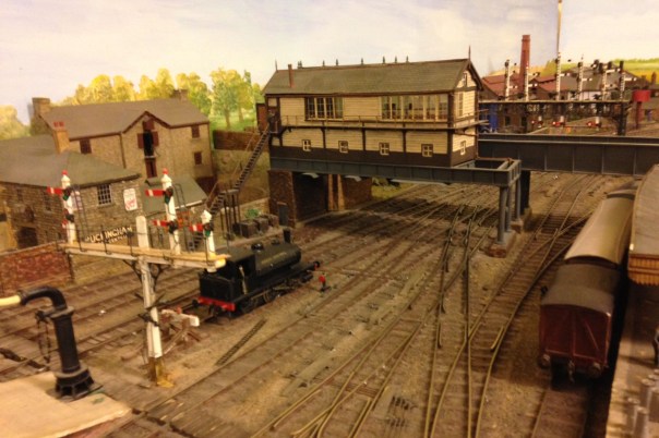
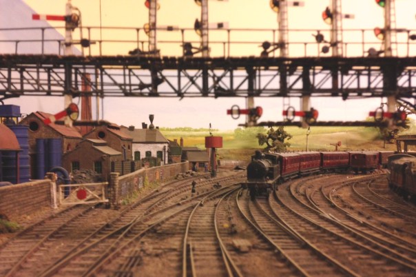
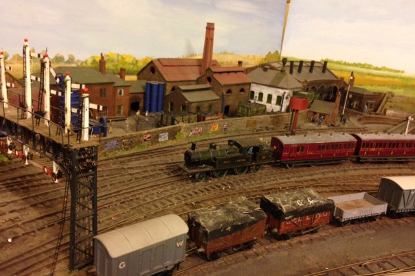
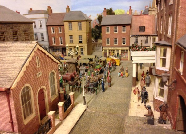
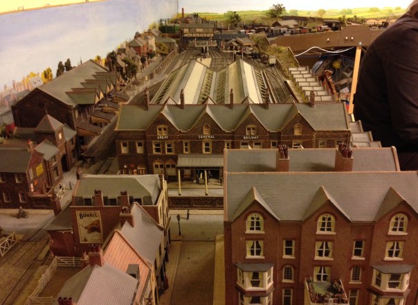
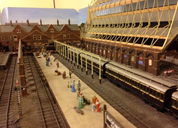
Whilst there have been several generations of layout, the core has always been an imaginary line to Buckingham from the Great Central mainline to London. Buckingham is, of course, a much bigger town in this imaginary world and justifies a fairly significant service of commuter, local, parcels and goods trains. In the view below, we see a “businessman’s express” for London readying for departure from Buckingham and then below that the peace and quiet of the station once it has gone.
As befits an important station, there is a complicated station throat, controlled by quite complex signalling and a fine box over the line.
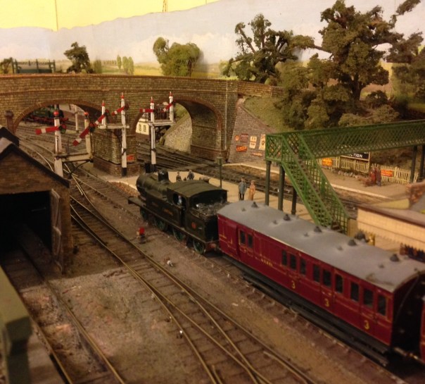
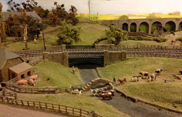
The other principal station was Grandborough Junction (the third station, Leighton Buzzard Linslade, was dismantled at the time of our visit). This was a busy junction and had a pair of branches going off it and crossing countryside.
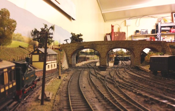
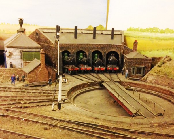
I particularly remember an article on “filling corners of your railway” – where he showed a gas works at one point and then an engine sheed – well here is that engine shed! Mindful of my turntable sagas (see November posts), I was half disappointed that this one worked so well – although it did have a very fierce growl when it operated!
Peter Denny was also a prolific writer so the layout adorned the pages of most of the british magazines – and even apparently a Japanese one! Certainly, it was a layout that I regularly read about in my father’s collection of back issues so it was a happy chance to see something that had a formative impact on the early days of my hobby. I still have a big book entitled Miniature and Model Railways – signed Happy Christmas Mark – from Gordon 1977! – that has a section on Buckingham which I perused before leaving to remind myself of the layout!
A lot of his articles were on building things for the layout – remember, this was built in the late 1940s, 50s and 60s and the alternative (when available which was rare) were tinplate. Here are some examples of the quality of Peter’s modelling.
The story as to why Peter Denny selected the Great Central Railway as his prototype is worthy of retelling too – as they made me chuckle. Apparently, he originally wished to model the Great Western and took his first completed model – a siphon (which is still on the layout) – to the Model Railway Club proudly one evening. There it was met with both admiration but also the sucking of teeth as various prototype details were pointed out as being incorrect. Now, woe betide me to say anything critical of Great Western followers but on the back of this, Peter decided he needed to find a prototype that less people knew about so that he would not get pulled up on technical details again! He rather liked the brown and cream coaches, so he did a search and found that the Great Central had them too – so a swap of allegiances was promptly implemented!
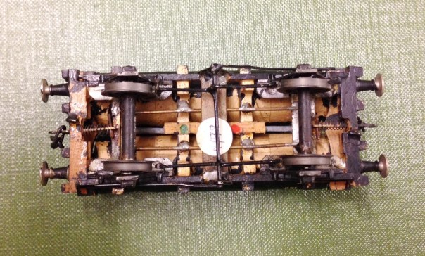
Resources were clearly a lot more challenged when Peter was modelling, most of the models make plentiful use of timber and card – it puts some of my efforts with much more sophisticated techniques!! Peter even used CSBs (see wagon below – well, nearly CSBs any; what do you think of that Will/Russ?).
But above all else, Buckingham is a layout for operating and is both very complex and quite simple at the same time. There is a substantial amount of electrical logic such that lines only become electrically active when they are correctly signalled. Even attempting to run a train in the opposite direction to that which is signalled is prohibited. All this uses hand built switches, many of which are mechanically linked to the single or turnout. As you would imagine, this creates a somewhat complex warren both above and below board!
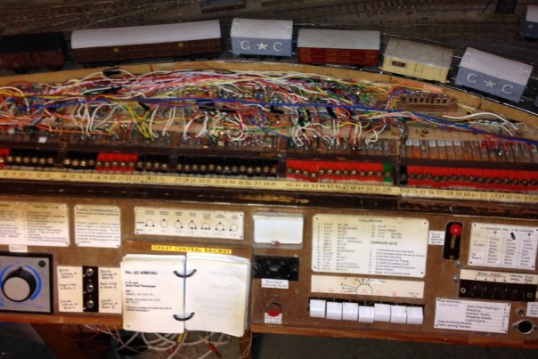
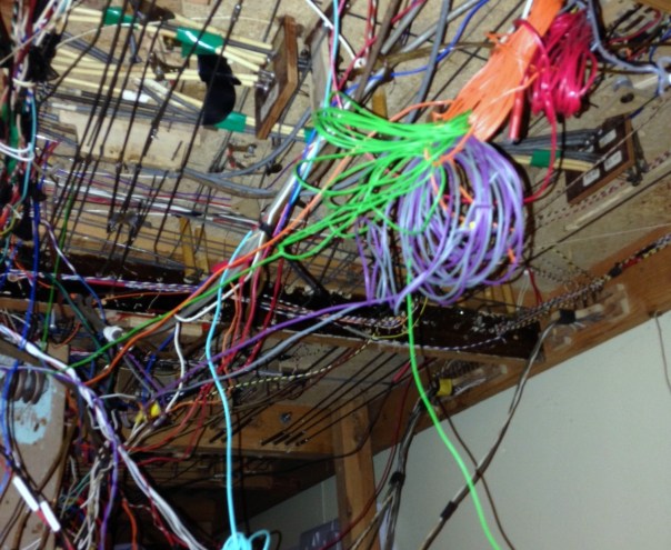
DCC anyone…………..
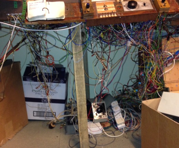
Even now, Tony is not fully aware of what the layout can do and there are plenty of teasers that need to be overcome to get it to operate properly – “aghh yes, this lever needs to be pulled over really hard to make the contact” but the next time “don’t pull that one over fully, or it doesn’t quite work“. It essentially needed to be caressed and humoured to operate – but operate it did even for ham fisted Tatlow!
We spent a happy couple of hours playing with the trains; dealing with arrivals, sorting out loco’s for the return work and shunting the platforms and yard. I thoroughly enjoyed myself – so thank you Tony and I’ll definitely come again!
I have now added a trackplan in an addition post here.
Glenmutckin Shed Area
Glenmutchkin’s shed area is modelled on Kyle of Lochalsh’s (it is a mirror image) and I wanted to capture the typically cramped feel of the inspiration. This is the original OS map for the shed (ie old enough to be outside of copyright).
Key to this is the way that the whole complex centres around the turntable and the first turnout is almost tight against the turntable’s wall as this photo extract shows (notice there is not even a buffer stop on the far side of the well):
The first turnout is, you will see, a tandom and whilst it is not visible in this picture, almost certainly it was interlaced (as the Highland always seemed to always use interlaced turnouts). Well, interlacing gets quite crowded on a tandom turnout, as you can see:
It takes a long time to do all of the sleepers as there are a lot of them but once it is done, it does look rather impressive don’t you think?
_________________
Mark Tatlow
Testing Times with Terribly Troublesome Turntables
A decade or so ago, I did start a MPD type layout and got some way with the building of a working turntable but had lots of trouble with it and this did rather kill off my enthusiasm for the layout – with inevitable consequences…………
The difficulty was to get it to operate smoothly, with any level of reliability, and to stop with sufficient accuracy to enable P4 wheelsets to enter and leave the turntable without derailment. Well, Glenmutchkin needs a turntable, so it is time to confront that particular demon again – and he has not gone away in the meantime! However, I think I have put the blighter back in his box with the help of the Chatham Turntable Drive, a chunk of scratchbuilding and a dose more cussing………..
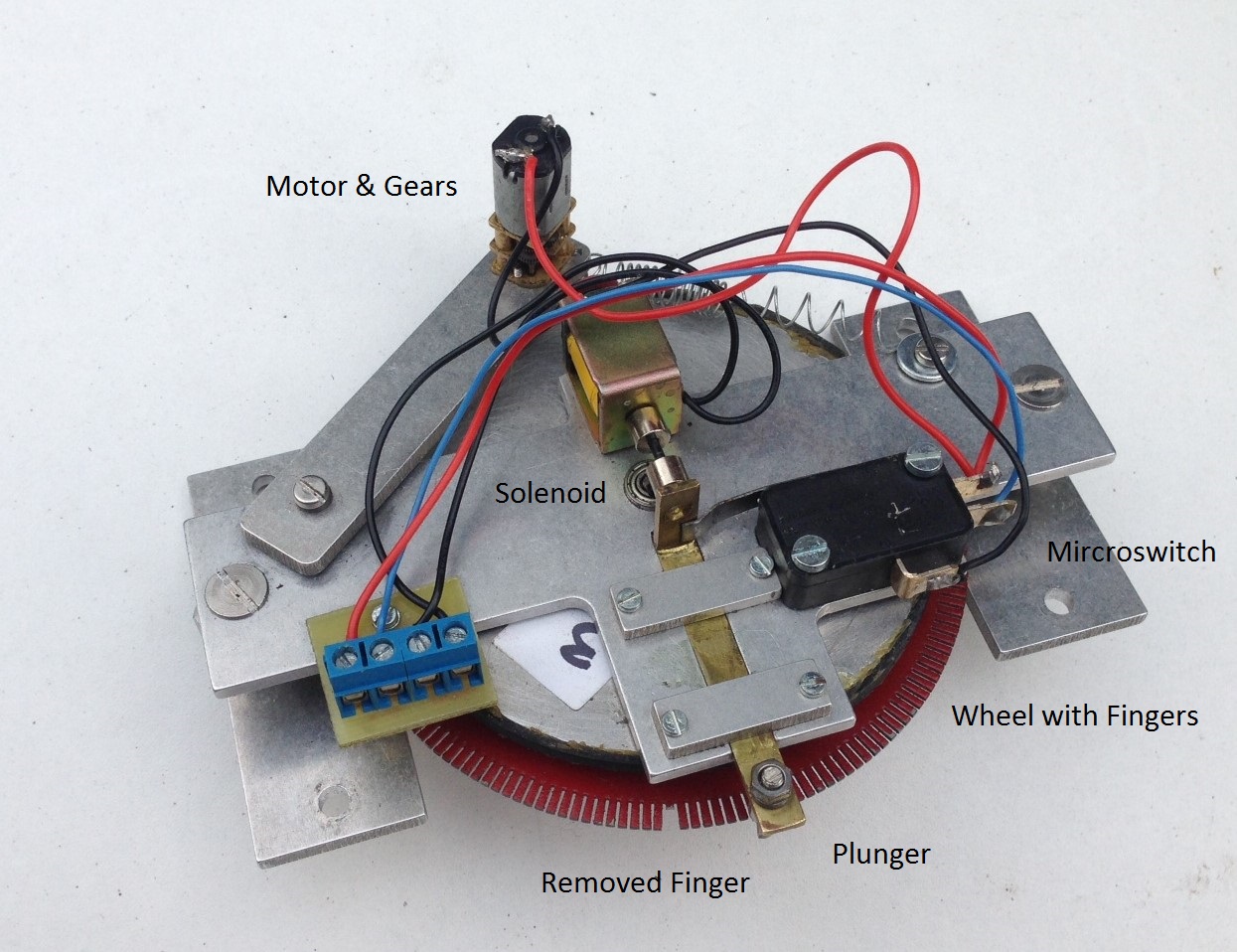
The Chatham turntable drive is named after its originator and is supplied in the UK by Model Railway Developments – not a great site listing I know, but there is a better Youtube video. The attraction of this particular drive was the mechanical locking arrangement – this means that it both stops consistently and then holds the turntable deck firmly there until activated again. The basis of the drive is a large wheel that has numerous fingers cut into it – the user then takes a finger away for the positions at which it is desired that the turntable will stop. When operated, a plunger runs across the tips of the fingers but where it encounters a gap, the plunger is pulled into the gap and cuts the power at the same time. To operate it again, the plunger is pushed free of the gap by way of a solenoid and the power to the drive reactivated.
The concept is great but there are some issues. The first was that the solenoid did not fully operate when activated. I found two problems with this; the first being that the control box seemed to send a less than full voltage to it. This was fairly easily dealt with by bypassing the control panel with the push button. The second problem related to the microswitch that alternates the power between the solenoid and the drive motor. The spring to this, even though it is quite light, was sufficent to offer to much resistance for the solenoid to overcome. I managed to overcome this by making sure that the rest of the plunger is as smooth as possible by rubbing all the parts down with fine wet and dry and a touch of oil. This takes a degree of care to set up to get the balance right and I am worried that it will be a source of problems for the future but for now it works.
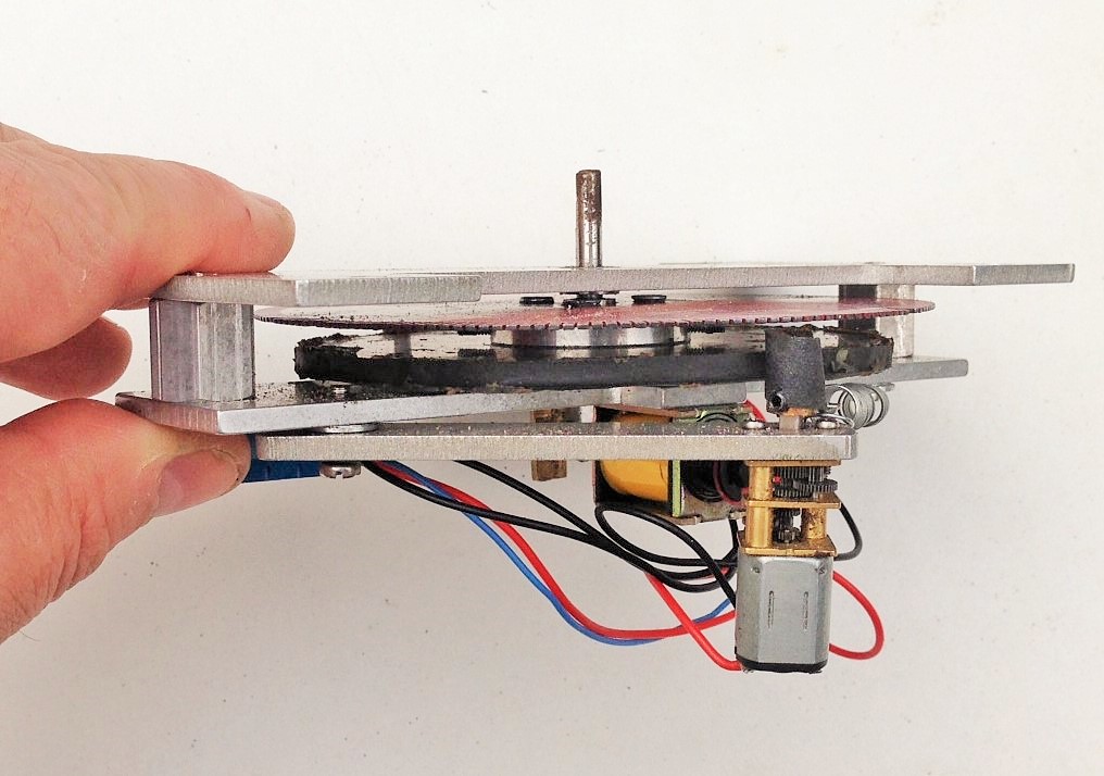
The next issue, is that the motor is not engaged to the drive wheel by a mechanical set of gears and instead has a brass wheel that runs on a rubber rim. This is probably designed as a safety feature to stop the motor burning out when a problem is encountered but it is prone to slipping rather too much. I have sought to overcome this by way of wrapping the motor wheel with sandpaper but this has only been partially successful. There are still more tweeks to do but I have found that it works rather better in one direction than the other, so this may be the ultimate solution!
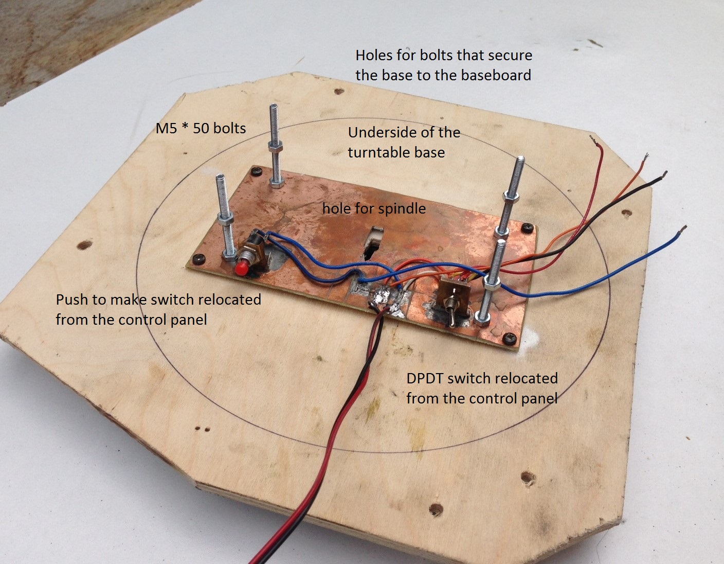
The next issue was to set the ride height of the turntable deck up correctly. I found that this had two aspects to worry about; the height of the deck relative to the rails that it runs on and then the height of the deck relative to the approach trackwork. I found that it is not sufficient to simply seek to try and get the deck set up correctly with fixed construction – it was simply too sensitive to minor errors. Therefore, I made up a mount with 50mm M4 bolts. By threading on a pair of nuts onto this, it was possible to adjust the exact positioning of the drive relative to the deck and then the entire assembly with the baseboard. The first of these nuts is shown on the above picture and once the drive unit is in place. the second set is tightened from above to hold it all in place. I am concerned, however, that they will loosen over time – so some “nut-tight” has been added to the shopping list!

I connected the shaft of the drive unit onto the turntable deck by way of a small piece of tube. This had grub screw clamps onto the drive unit shaft and a permenantly attached bolt on the top (bottom in the picture). The rod to the base of the turntable deck was reduced in diameter slightly such that it would rock just a touch and take up any inconsistancies in the turntable well. However, I ensured that the bolt was tight in both the rod and tube, so there was limited backlash.

Next up was a turntable well; which was another area where the gremlin made itself felt last time. Most of this had to do with trying to get the turntable deck to sit squarely and equally in the well. As already noted, I adopted the oppisite approach this time and built the well to fit the deck and simply relaid the rail afterwards so that it was exactly above the pivot – it has proved to be a whole lot easier and could have saved a lot of frustration last time!
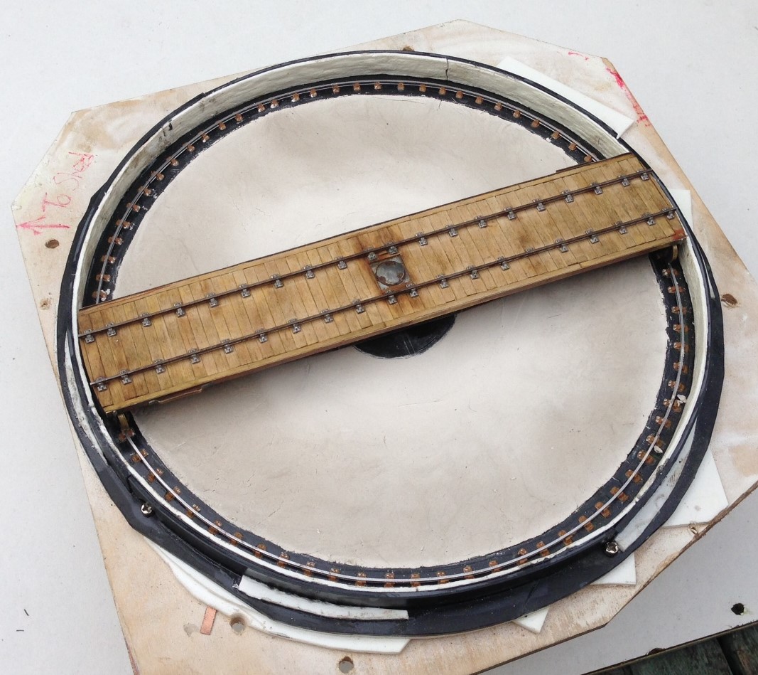
The well walls were formed of Will random stone sheet, as I did not think that they would have used anything particularly fancy on a turntable well. However, to stop them springing out of the curve, I laminated this with a chunky thickness of plasticard and also secured them to a plasticard base – this also formed the base for the rail, which is secured in turn with Exactoscale chairs. One thing I did notice when studying prototype photos is that the chairs on the turntable rail are quite closely spaced – presumably because a relatively limited number have to support the entire load of the engine (much less in number than in plain track due to the deck carrying the entire weight of the loco onto only four points). I have replicated this on my deck.
The dish to the well was, I have decided, merely ash ballast in the pre-group era (neat concrete was a much more recent approach), so I formed this with Das pressed into place and made as smoth as I could make it with fingers. This never gets crips and “machine made” so represents what I think it will have looked like.
I will look at the deck in the next post, after which hopefully it can be shown fully working and in situ! However, here is a peek:

….alliteration with thanks to Mrs Bennett; I really do remember Magistrate Maskew of Moonfleet Manor……..!
Ton Up – aka Ben Klibreck
Today has proved to be a fairly big day, but not for modelling reasons.
Today I climbed Ben Klibreck, which is the second most northerly Munro in Scotland. Not in itself a hugely remarkable mountain, not particularly high or with any major technical challenges. Mind you it does (as you will see below) have stupendous views of the wildness of Sutherland from its top or approach ridge.
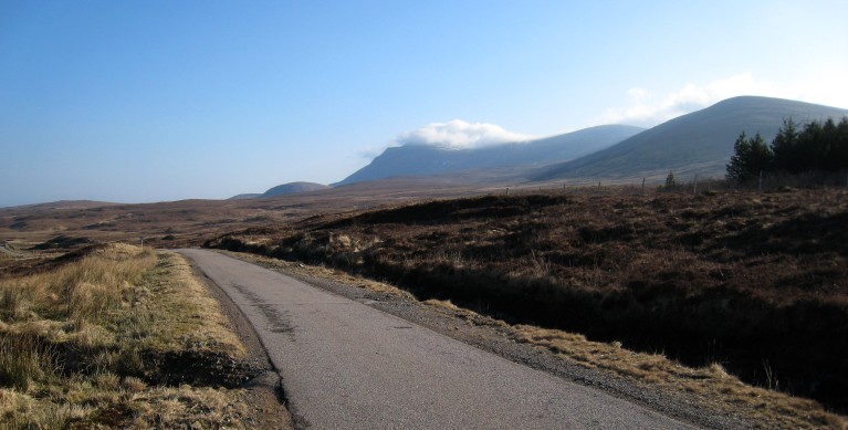
Ben Klibreck from the south west

Looking north west from the assent of the approach ridge to the mountain

and a panorama around the north.
And the reason why it is such a significant mountain; it marked the completion of my 100th Munro. All I have to do is crack the next 182 out now……………..
Although, maybe some modelling too……………but first a bath and bed!
Gresley Buffet – Part 3; Corridor Connections
I guess that it is pretty difficult for the RTR manufacturer to take a stab decent corridor connections because they have to design for toy train set curves and clumsey hands but it is a weakness of all proprietary coaches. Hornby’s buffet also seems to have overly skinny corridor connections and most noticeable they are mounted too low – they should finish at the meeting of the roof with the ends.
Whilst it is possible to simply slice off the connections off and move them up, I chose to remove the and them with some produced by Comet – as this is an LNER vehicle, you need the Pullman type. The core of the operation of the corridor connections are the bellows which are formed with a pair of sheets of fairly stiff paper. These have slots cut to half their width and are then folded into a concertina shape, with the slot between the folds. Two such pieces are then offered up to each other, with the slots opposing and these then slide over each other as shown in the first picture.
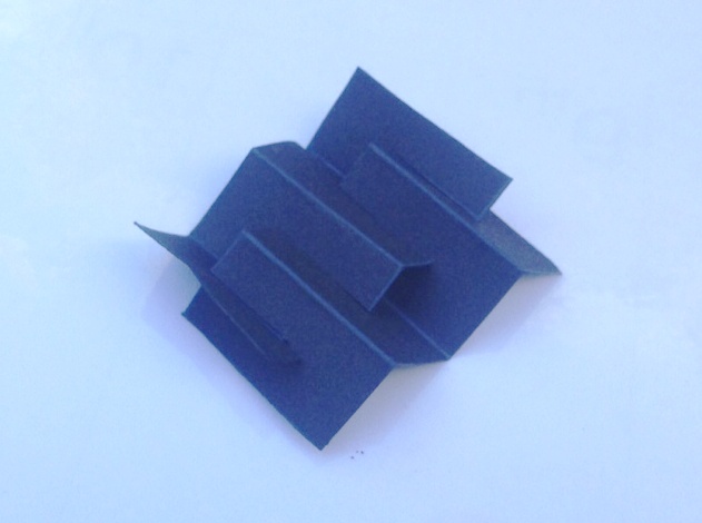
To create a concertina bellows like this.
Thereafter, the etched end plate is attached to one face. Whilst not provided in the kit, I formed a second plate from plasticard and affixed this to the other end. it is important to ensure that no glue gets on the concertina sections of the paper, as they need to be capable of compressing with minimal effort to correctly operate without derailing the carriage.
This is how Comet envisage that the completed connection should look like but I felt that the bellows did not look very realistic, especially from above where the crossing point is all too obvious. In practise, the top of these connections had a fabric roof and applying this dramatically improves the appearance of the connection and has the added advantage of providing some control to the operation of the connections which do tend to expand out and look rather flabby!
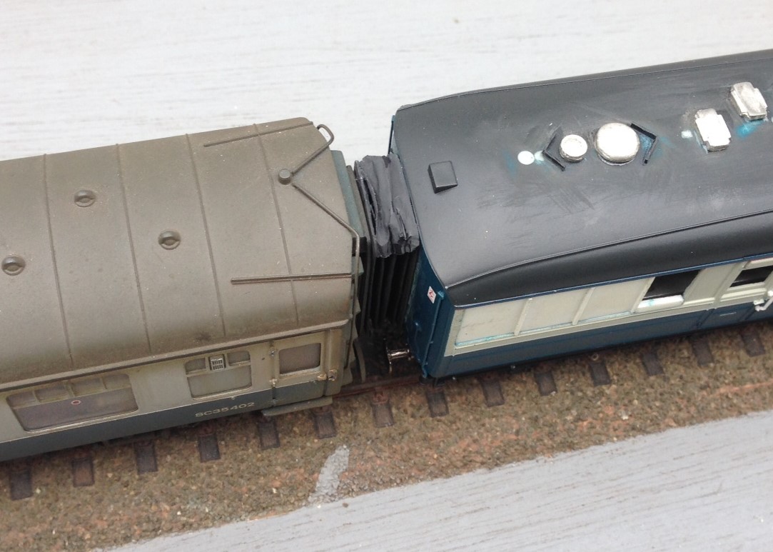
I dealt with this by putting the rain hood on the top of the connection, which is afterall prototypical (and makes a huge difference to the appearance as you can see). I did this in a manner that meant it acted as a restraint to the movement of the connection. I acheived this by only gluing it at the very back and front of the connection, so that the bellows could move unimpeeded but once they had moved to the required extent, the rain hood pulled tight and stopped them going any further. I found that doing this at the top was not sufficient as their movement continued at the bottom and they took on rather drunken appearance – however, this was solved by simply repeating this at the bottom.
Key to getting this to work was to use material for these restraints that was ultra flexible. I did think about trying silk but settled instead on the rather more mundale – plastic from a bin liner. This is remarkably thin but is still tough enough to hold the connections. A tiny dab of super glue at the front and back and then it can be laid onto. It is important not to sigh with releif for some time though – the stuff is so light that it blows away at the slightest. So this is what it looks like:
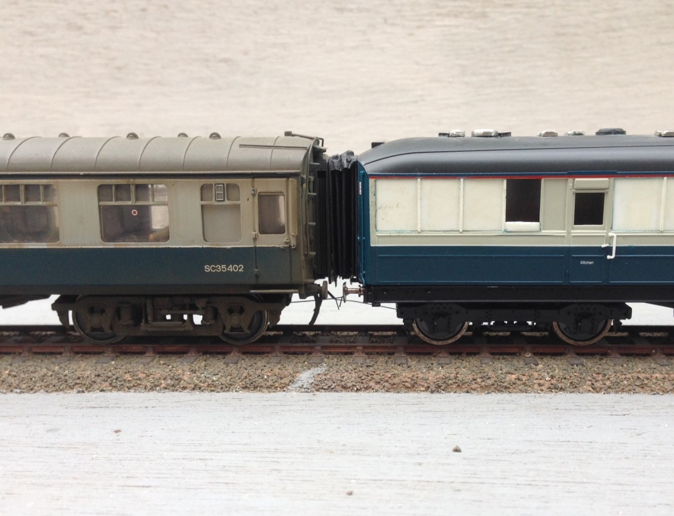
I think that I have still allowed the connections to be too big and if there were two together this would definitely be true but next to a rather skinny Bachmann corridor connection, I think they look pretty good (and a big improvement on the originals).
Scrap Tank Test Build Part 9 – Finishing the Body
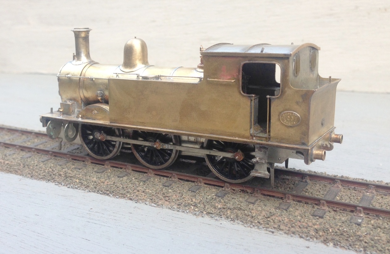
I have now had the castings back for the various fittings for the Scrap Tank; the masters being in part my own 3D prints and some turnings that I commissioned from Jeremy Souter. This is what they look like:
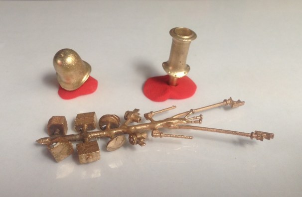
I did not seek to do everything for the whole model as some parts are available from other suppliers and I did not want to duplicate their work. Thus, I needed to get the safety valve/safety valve bonnet from Alan Gibson, a smokebox door from Lochgorm, a whistle from Markits and smokebox door handles from Comet.
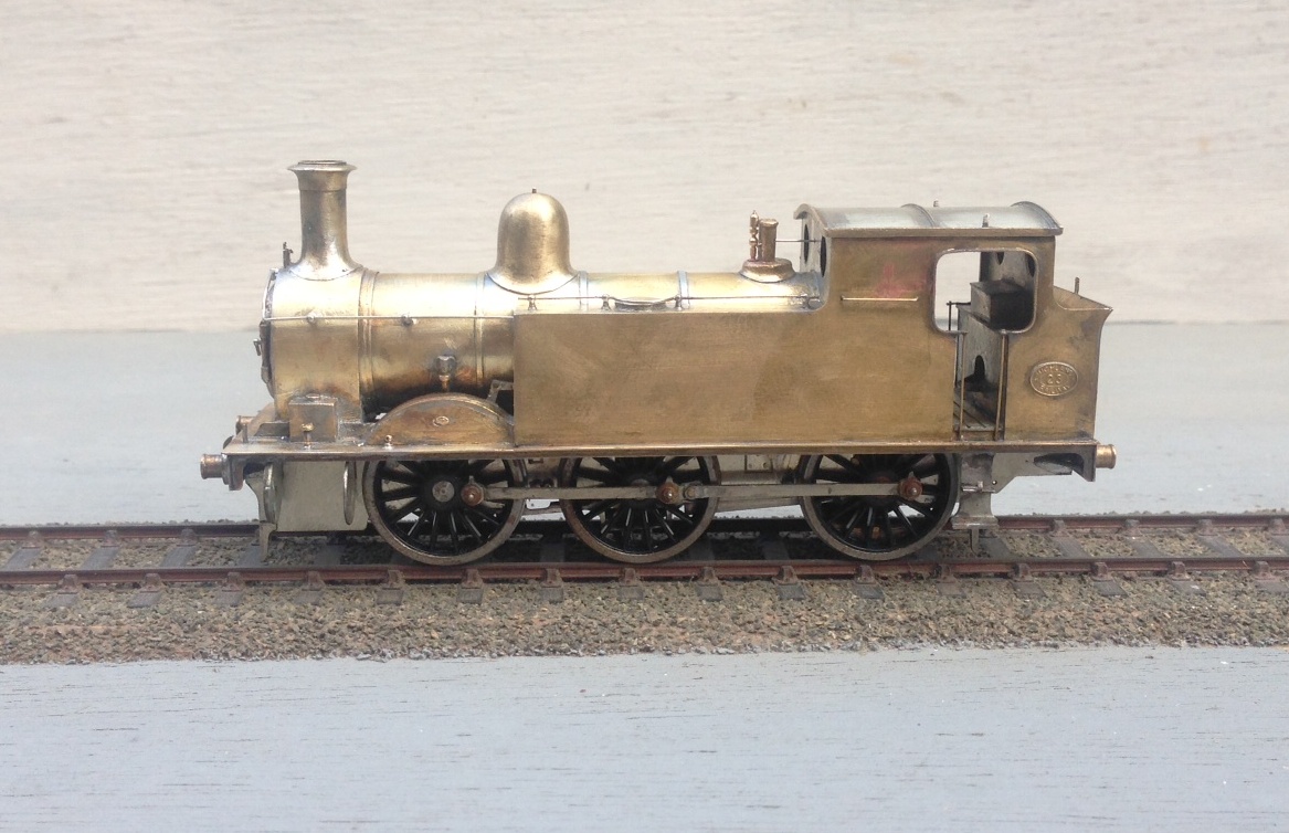
Once these, along with the remaining handrails, were fitted, the body is complete and it certainly appears to be taking on the character of the real thing so far as I am concerned!
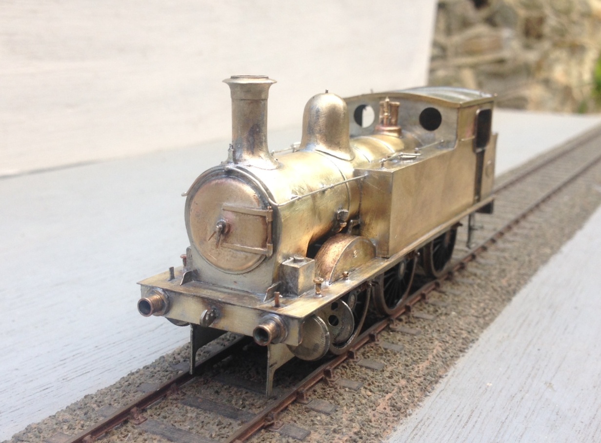
So next up will be the cylinders, crosshead and connecting rods!
