Blog Archives

Early Pattern Lookouts for Dia 38 HR Goods Brake
I have been doing more with the Scrap Tank, but I haven’t managed to take any pictures due to needing flippers outside yesterday. So instead, lets see something else that was on the test etch that I have recently had returned.
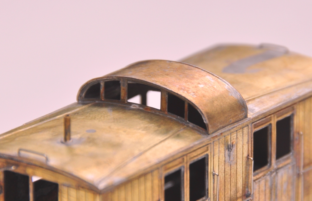
This is the early style lookout for the dia 12 Highland Goods Brake. As originally built these lookouts formed by a single slot to the centre of the roof and were fully glazed to the front and back. In use guards complained that they caught their heads on the lip of the roof as they climbed in. To overcome this, many of the vans were rebuilt to include ramped approaches to the centre of the lookout were incorporated, to become what was arguably the signature feature of the Highland’s rolling stock.
Microrail produced a kit for this van 30+ years ago and this included the latter style of lookout. I had a pair of these kits and ended up acquiring a third one and I felt I really could not have another one just like the first two! So I had an inspiration and thought it would be fun to make the early pattern lookout. The old man’s book came out and a scan of the drawing loaded up into the CAD machine. From here it was a relatively simple exercise to draw up the difficult bits, the glazed screens, and the more simple roof.
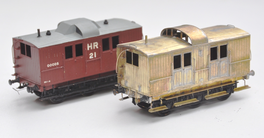
The components went together easily and do give a very different feel to the Microrail kit as intended. I also made a number of other adjustments, to the footboards and also the panelling, to make the model both different and authentic. The latter, the beaded panelling, is a right pain in the whatsit and took much longer than any other element of the assembly – so don’t to it unless really want to! And this is what it looks like next to the kit as originally intended, with the later style lookout.
I will be making these available via the Miscellany Models site shortly, when I have done enough of the other elements I am working on to do a production run. In the meantime, I do have a pair of very slight seconds (there is a tiny bit of over etching – almost impossible to see, the pictures of my vehicle have the same problem). These are available for the price of the metal; say £2.50, plus postage (which won’t be much). Ordering is via here: http://miscellanymodels.com
And the real thing looks like this:
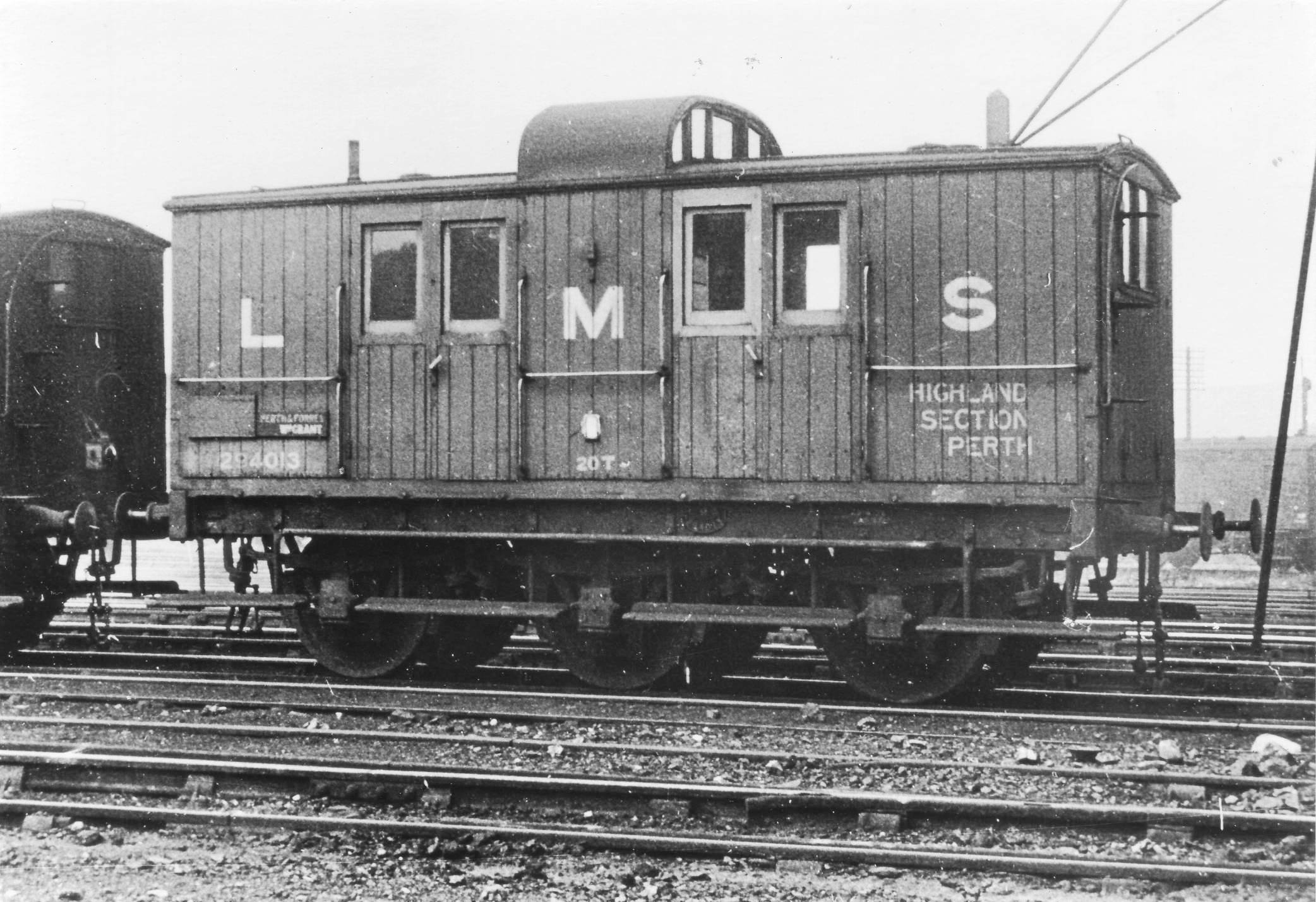
(C) Bill Steel
Scrap Tank Test Build – Part 2; Continuing with the Body
The next stages of the test build were to do the footplate/tank sides/can exterior.
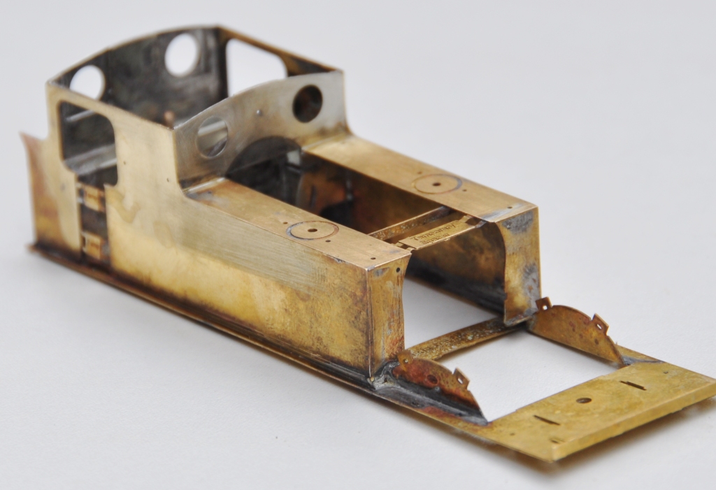
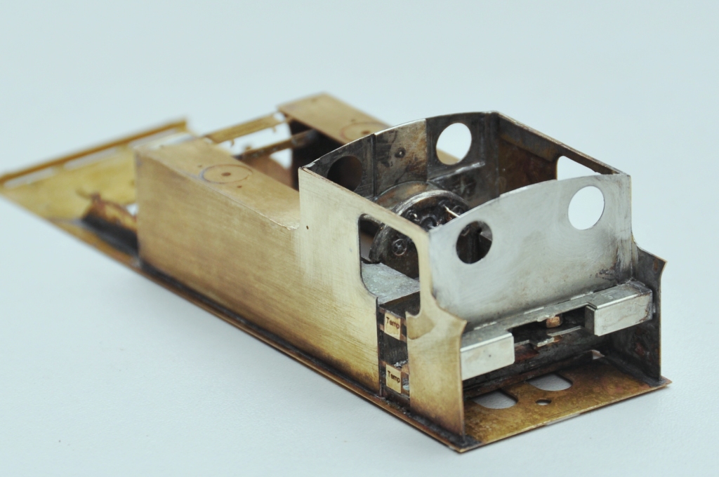
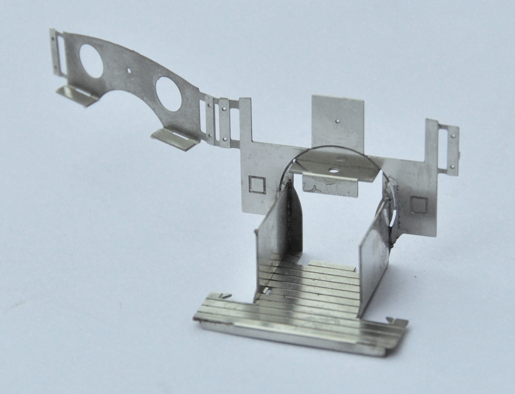
My initial design for the footplate is not particularly radical, but the test build has shown up that until the boiler is put in place (which comes some way into the build process) the front is somewhat delicate, irrespective of whether the footplate valences are fitted or not. Thus, in addition to the temporary stiffener that can be seen to the front of the footplate in the picture below, stiffeners will be provided to the front half of the footplates. The idea of these can be seen in the following view which shows the rear of the cab. By folding these over at 90o during the build, they give strength to the more delicate parts of components. Some will be incorporated into the finished article, others will simply be discarded when their job is done.
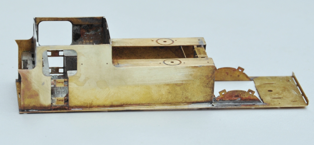
The two tanks, along with the sides to the cab/bunker, are conceived as a single piece (if you go back to my previous posting, you can see this in the flat in the etch). The two halves are separated by temporary spacers to both assist in locating them but also to give strength to the assembly prior to the fitting of the boiler which is where it will get its strength from. It was when I tackled this part, I reached the first disaster – the etchers had failed to half etch from behind so I was missing some fold lines. This was pretty frustrating as it entirely negated the intended efficiency of the design and even though I now have a corrected etch, I had to solder on by cutting the parts at the intended line of the half etch and soldering them together in the more traditional manner – exactly what my design was intended to avoid. As a result of this, there are no neat photos of the tanks being folded up and secured in place, we have to jump on a bit to see this.
The cab fronts that were constructed earlier were no slid into place and I was pleased to find that it all fitted very snugly and in exactly the correct location. I did find that I could put in a further pair of fold up tabs on the running plate that meant that it was essentially impossible to put this in the wrong location, so this is another little refinement that will make its way into the production batch.
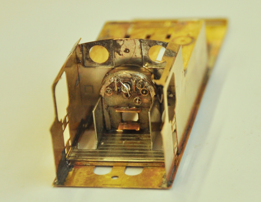
The rear of the cab was a similar fold up unit to that to the front, which was pretty easy to build but did have one dimensional error at its base that needed cutting away – well that is the purpose of a test build! All of this, has been created from one piece in maybe three minutes!
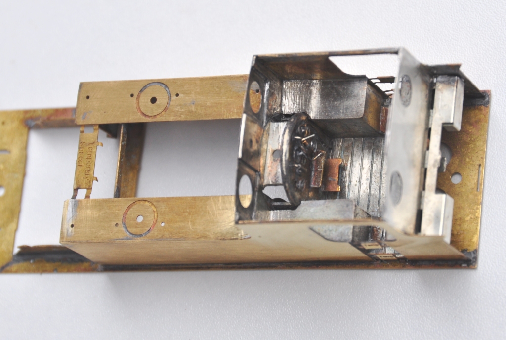
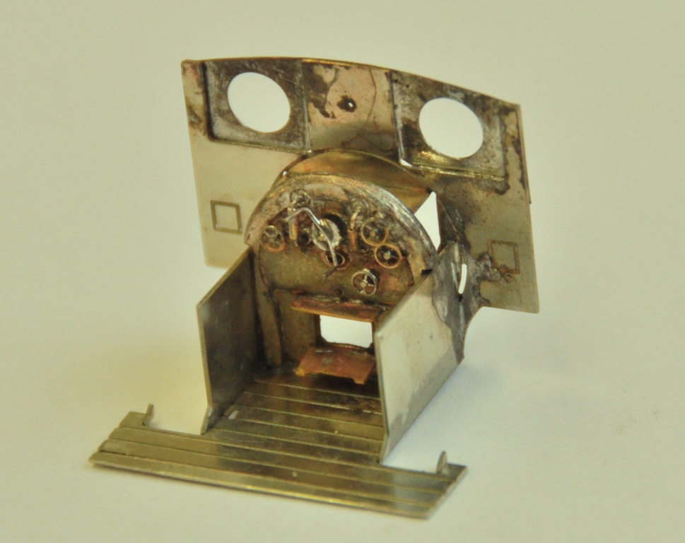
And this is what it looks like with the cab rear in place. If you look carefully, a couple of 12 BA screws are just visible in the cut out to the rear of the cab – the purpose of these will become apparent in a future posting but it is another one of my little ideas to make this easier to build/better when built.
And this is what the cab bow looks like from above, after the addition of the splasher tops and backs. One of the issues this illustrates is that this kit, as it stands, will only work for EM or P4 modellers. There is insufficient room to get the narrower gauge/wider wheel treads into the splashers.
Next up will be the cab roof………….
Scrap Tank Test Build – Part 1; Getting Started
I took the weekend off the other week and attended the Spring Railway Modeller’s Weekend at Missenden. It is great to spend two full days just modelling away from the distractions of life and amongst people who are all doing exactly the same. I find it a form of therapy and it is well worth going if you have been thinking about it (and even if you haven’t!).
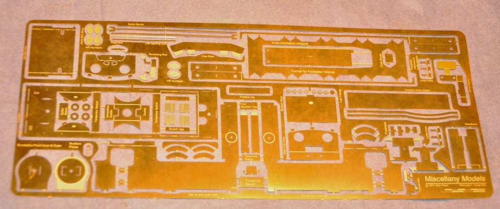
I took with me the etches that I have had delivered by PPD for the Scrap Tank; with a view to doing a test build using them. The origins of this class are some of the earliest locomotives built for the line; the Raigmore class. In an attempt to increase the life of these new enlarged boilers were fitted to them. Unfortunately for the Highland Railway the boilers were too heavy for their frames and consequently these cracked. This left the Highland with a number of new boilers, wheels and many fittings but no locomotives! Ever the frugal, they recycled these parts into a series of three shunting locomotives which were designed by Peter Drummond and these inevitably quickly picked up the name of Scrap Tanks.
These were rather brutish looking locomotives for the time, characterised by surprisingly large wheels for a shunting locomotive – something compelled on the Highland due to them reusing these from the Raigmore class which were mainline passenger locomotives with 5′ 3″ wheels. For those of you who don’t know what these looked like, this is what we are aiming at:
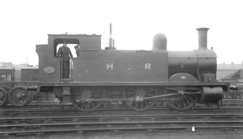
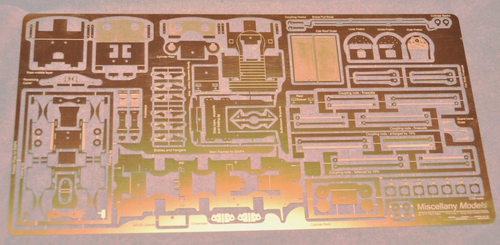
And this is what we are starting with:
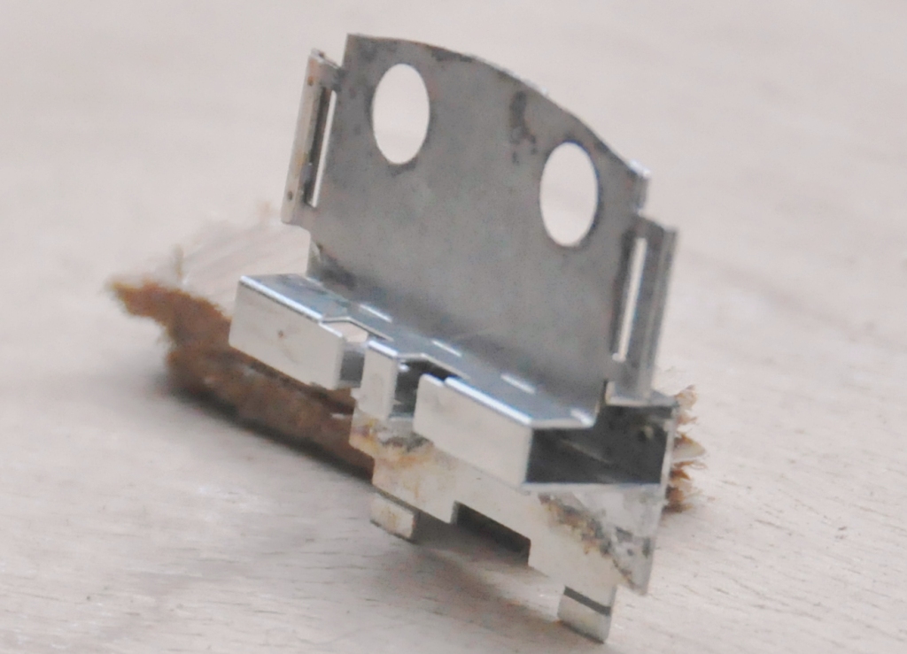
Whilst this may (well has!) got me into some trouble, I have sought to design the kit to be easier to build than the average etched brass kit and certainly easier than the Falcon Brass kits that are the staple in 4mm for many of the Highland’s locomotives. I have sought to do this in a number of ways and the first area tackled, the cab front/interior, illustrates one of these; the use of fold up assemblies to assist not only in creating the shapes but also the laminations. Many of the modern etch designers are using these (especially the 2mm boys/girls) but I have sought to do rather more than most (which has made the preciseness of the design rather more challenging, more of which anon).
The bulk of this assembly starts as a single piece, that is folded up to form the cab floor, splasher sides and the bulk of the cab front. To assist the lamination process, jigs either side of the cab front have been used. Wire rods are slipped through the small holes in these to ensure that they are registered on top of each other properly.
The view below shows the laminations now sweated together and illustrates the square cut outs behind the cab front which are to enable glass/Perspex to be slotted in to represent the sceptical glazing. The view also shows the boiler backhead which is made from three layers of etch (not with a folding jig – yet!). I am pretty pleased with this as this is only 13 * 15mm in size, so the wheels on the backhead are only 2mm in diameter.
To be continued…………(soon too!).
No Point Hanging Around
Whilst I have not put any posts up showing progress with the boards for Glenmutchkin, progress is being made and the last two boards are essentially now finished. I am hoping that with one more day’s work which will mostly be to build up a carrying box for the final two, they can all come home.
In anticipation of this, I have been building some turnouts and a bit of the basic trackwork.
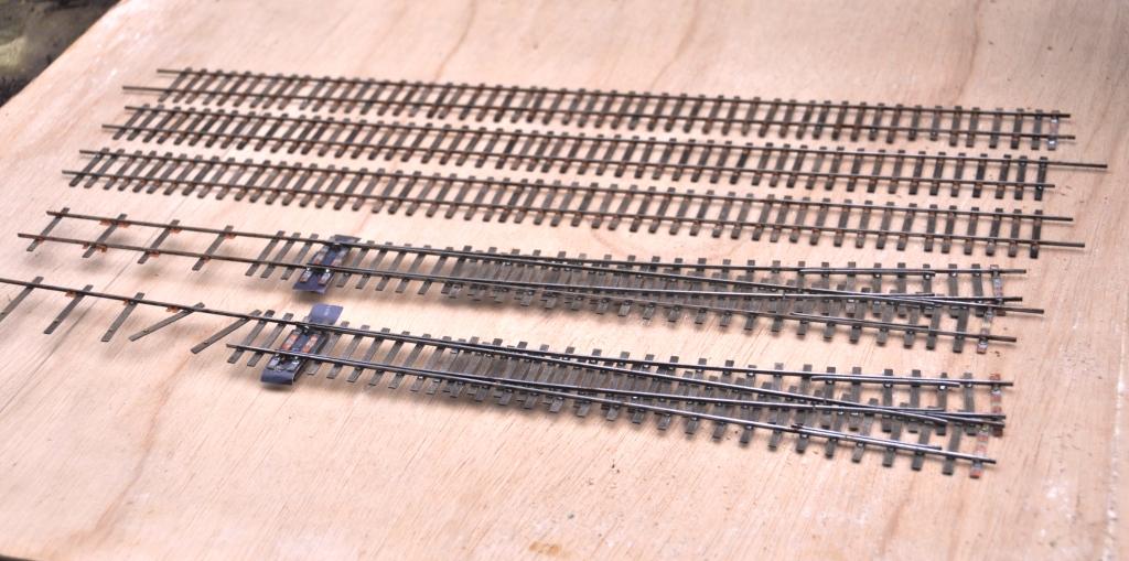
I am only able to do the turnouts which I am reasonably confident will not change shape when the track is finally laid out on the boards. In essence this means the crossings in the bay, the main line and the goods yard. I have also done one of the turnouts in the yard. So seven down, twelve to go including a slip!
I have also developed my approach to TOU’s slightly from Portchullin. As a finished article they look like this:
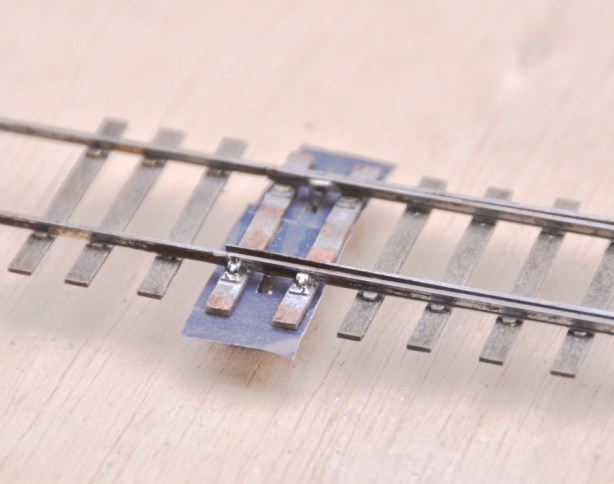
You will see that relatively little of the TOU is exposed (and when it is painted it blend away further). Equally it is much more durable than most of the other options out there because the switchblade is held by both a wire strip but also to some brass strip that is tight to the underside of both the switchrail and the switchblade. By installing this strip in this location, the switchblade is held in a vertical plane much better than other solutions. I think this leads to better running.
This is what it looks like as it is being assembled. You will see that in essence is it is merely a bit of copper clad below the switchblades, but lowered somewhat further due to the use of the brass strip. This allows the whole lot to be hidden below the boards.
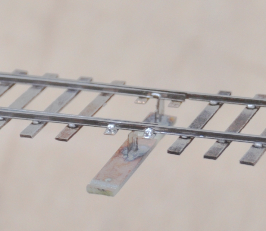
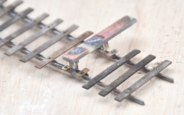
You will note the rather unusual arrangement of sleepers. This is called interlacing and was very common on many pre-grouping lines, including the Highland. I will expand on this in a future posting.
Christmas is the season for…………. jolly well finishing stuff off!
Over the break, I have been concentrating on trying to finish things. Like many people, I find it much easier to start a kit or project than it is to get it fully finished. Indeed, do we every truly finish our models – certainly not our layouts!
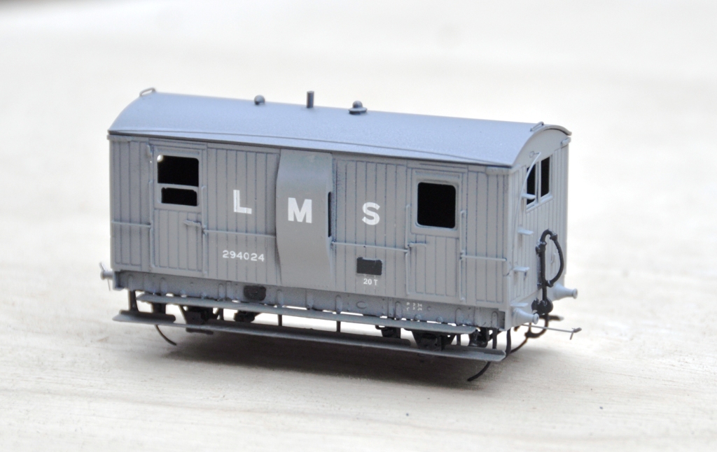
Back in March 2013, I completed a dia 39 goods break. These were the final Highland Railway break vans and it is not clear that they were actually finished prior to the end of the HR era. Given that I model in the mid 1920’s, I am quite content to do this in LMS grey which to date I have not seen the model depicted in! The main body painting has been completed and the van has been lettered but weathering, the interior and final detailing/glazing is still to be completed. Based on the Lochgorm Models kit with minimal adjustments (a few pipes below the chassis and sprung W irons in lieu of the compensation provided in the kit) this is what it presently looks like:
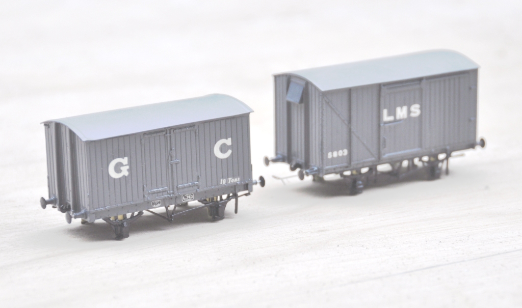
Also coming through the paint shops are a pair of vans. The first is a Great Central van build from a Mousa Models etched brass kit and the other is a LMS early standard van from an injection plastic moulded kit from Cambrian Models. Both are pretty simple models to build; the Mousa Models one was built as designed and no adjustments were found to be necessary. I only fitted springing to the Cambrian one and got rid of the rather too thick W irons in the process. Again the bulk of the painting is complete, but some dirtying work is definitely still required.
Apologies for the slightly squiffy photos; I left it a bit late in the day to take them and the light was poor. I have made a lot of progress painting the NER hoppers, but the photos of these really did not make it and need to be repeated. Something to post tomorrow I suspect!
HR Cradle Bolster – First Test Build
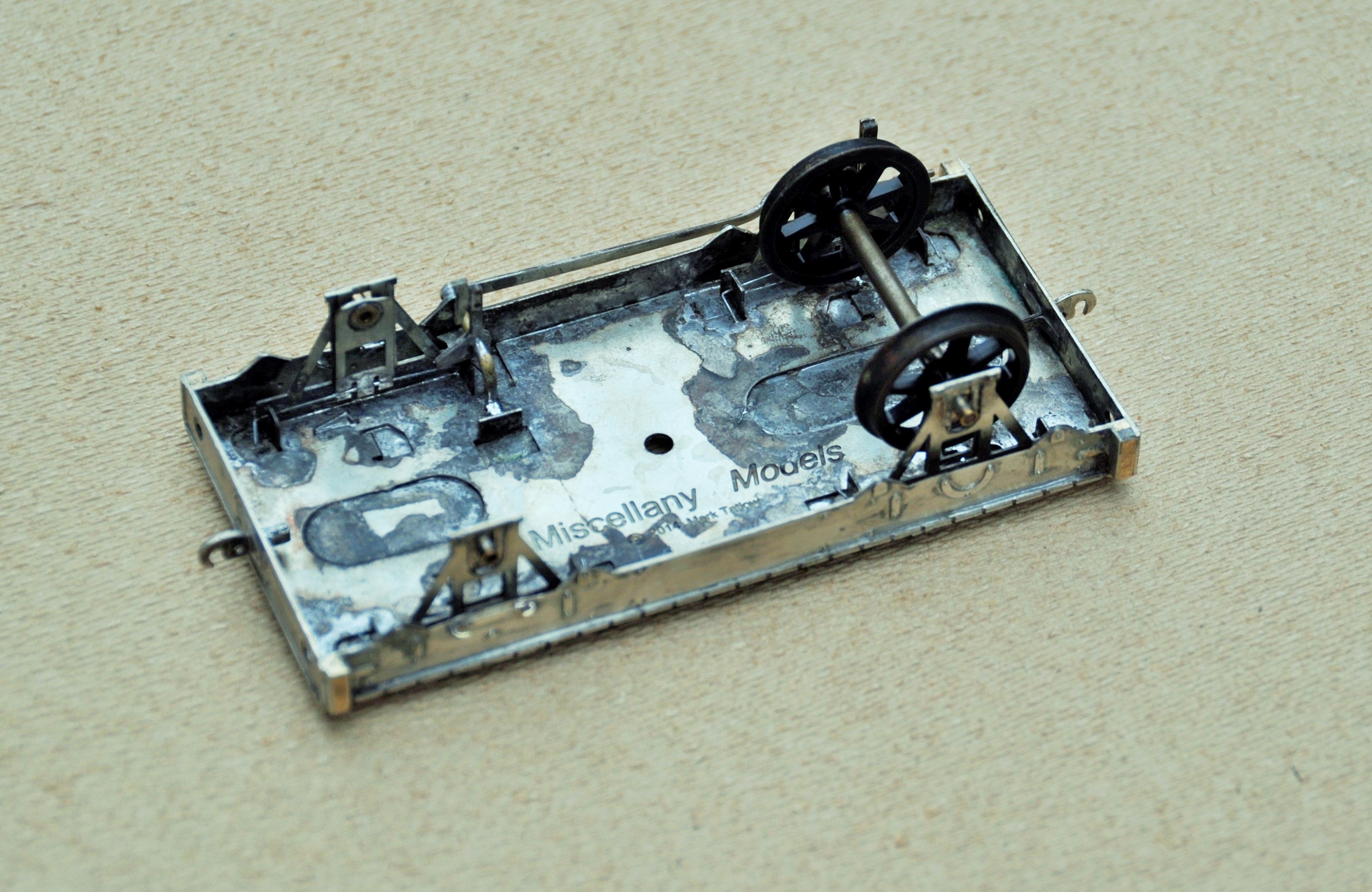
I had a delivery from PPD a week back, so I have been playing with some test builds of this:

This is a dia 25 cradle bolster; a type of vehicle that I have not seen on another railway. It has a square cradle that sits on the top of this, with four bolsters protruding from the corners of the cradle. They were used on pairs and the whole cradle rotated when the pair of vehicle went around curves. The intention, I presume, was to offer the load more support by offering more points of contact. Anyway, as no one else had tackled this vehicle before, I thought I would have a go!
As this is my first etched design for a vehicle, I have certainly encountered a number of problems. As the top photograph shows I produced this in both 4mm and 7mm; the latter has proved more successful due to the thickness of metal being greater. The main issue that I created for myself was to half etch the solebar overlays so that the rivets and the ironwork could be portrayed. However, rather than backing them on a further layer of etch (like the etched kits I have built – they evidently knew something……), I spanned it between supports. The intention had been to make the kit fold up more readily but in practise what has happened is that the half etched solebars have distorted (badly in the case of the 4mm one) due to the stresses introduced in the heat from soldering. Thus, whilst I have a working model (at least in 7mm), a rework is going to be required.

Both the 4mm and 7mm versions will have sprung axleboxes, using a varient of the guitar wire sprung version used by Bill Bedford and others. The 7mm chaps don’t seem to use it much and I guess the mass of their models helps. However, it does glide with the springing and is better as a result I reckon.
I have also done a 3-D design for the cradle, which I am proposing to use as a master for some resin castings (certainly in 7mm, I might go down the lost wax brass route in 4mm). A new process that I have not previously attempted. I need to find out where to get axleboxes and buffers from – Larrie Griffin I presume.
Also back from PPD, were some etches for something altogether more bold (which is a worry in the light of the problems I have encountered on a relatively simple wagon!). This is the chassis and body etch for a Drummond Scrap Tank. I have made a start on this and again, some reworking will be required but again there is a viable model in an amongst these parts; it just needs tweeking. More to follow once I have got further with it.


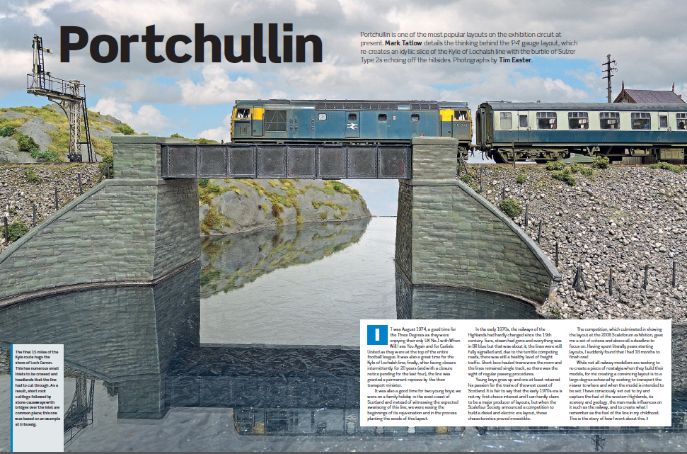
Portchullin – Recommended Reading
Portchullin is in the press!
Rail Express have for many years included a modelling section to what is otherwise a prototype magazine. This year (and going forward in future years I beleive), they are producing a yearbook which is dedicated to only modelling features. Portchullin is the leading article with a series of photos from Tim Easter – and it is no less than 13 pages long.
Here is a taster and if you want to get a copy, it can be obtained here:
First Four Boards Complete!
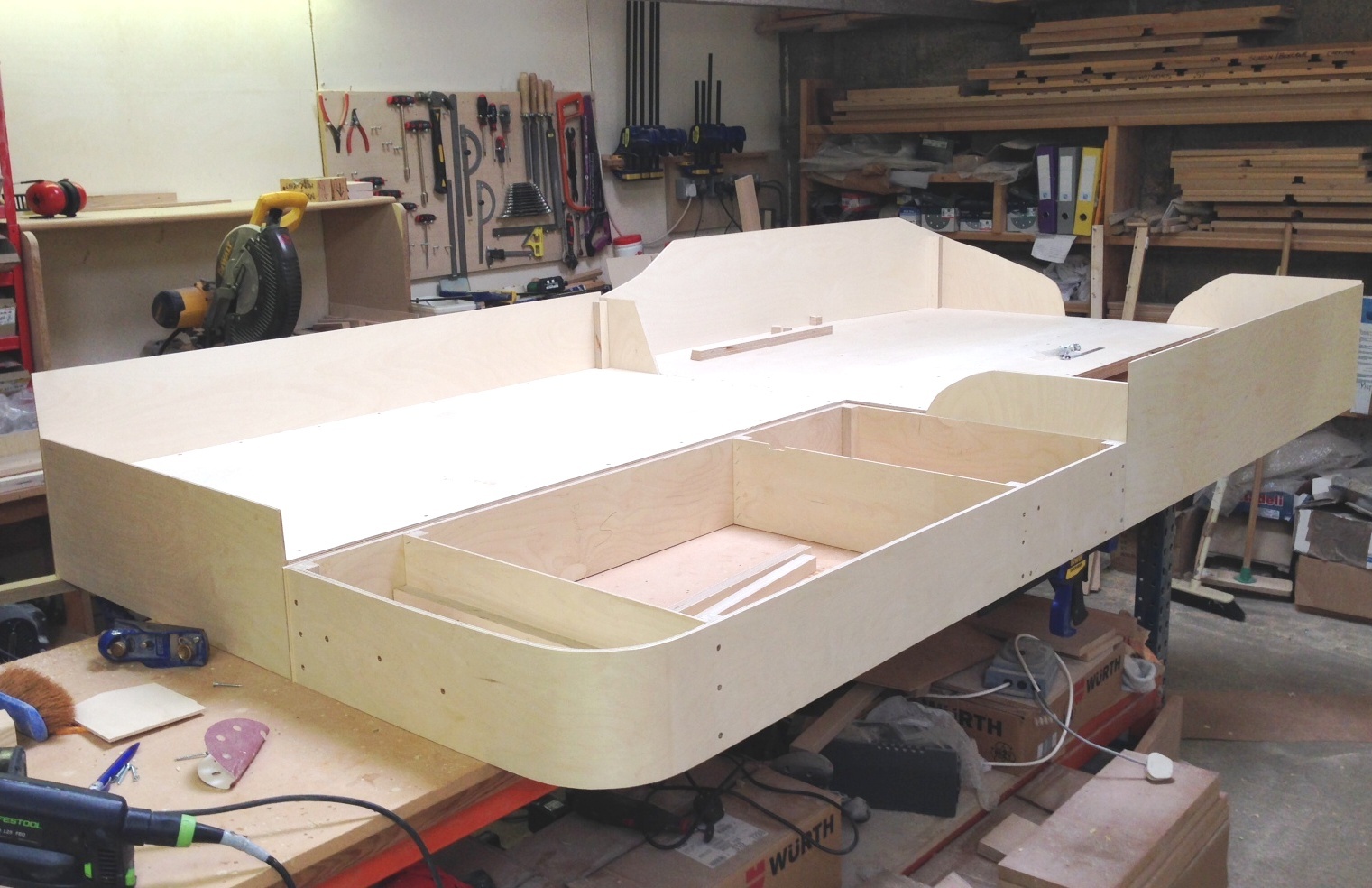
Julian and I have been putting a bit more time in on the baseboards, to the point where the first four are complete with the exception of their varnishing/painting.
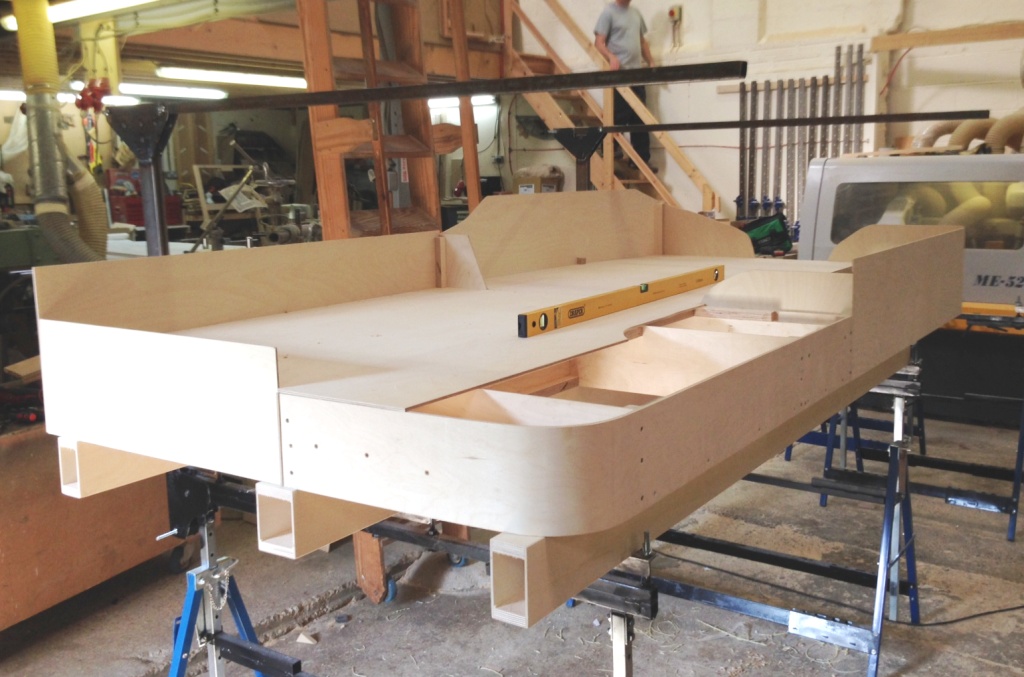
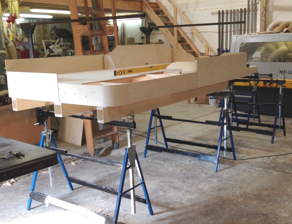
You will also see in the pictures that the beams that support the boards have also been completed. These span between the brackets that were shown here which in turn are supported by bolts that have been affixed to the builders trestles. This means that each point of contact can be adjusted for both overall level and also cant. The idea is that this is done prior to placing the boards on the beams, so that the whole thing can be levelled as one and the boards then just get plonked on. So long as the floor is not too wonky (like that in Tim & Julian’s place!), this does not take long and it is very idiot-proof assembling the layout perfectly each time.
Also visible in the views are the gallows brackets that will support the lighting and facia. These are fairly meaty as they have to span over 1300mm from front to back, so the moment on them is quite high. What we have just found is that they are a tad low due to the beans being a bit higher than I had expected. A bit of adjustment will be required in due course; especially as the layout level is also a bit high.
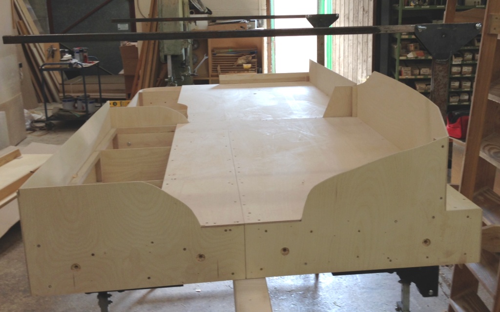
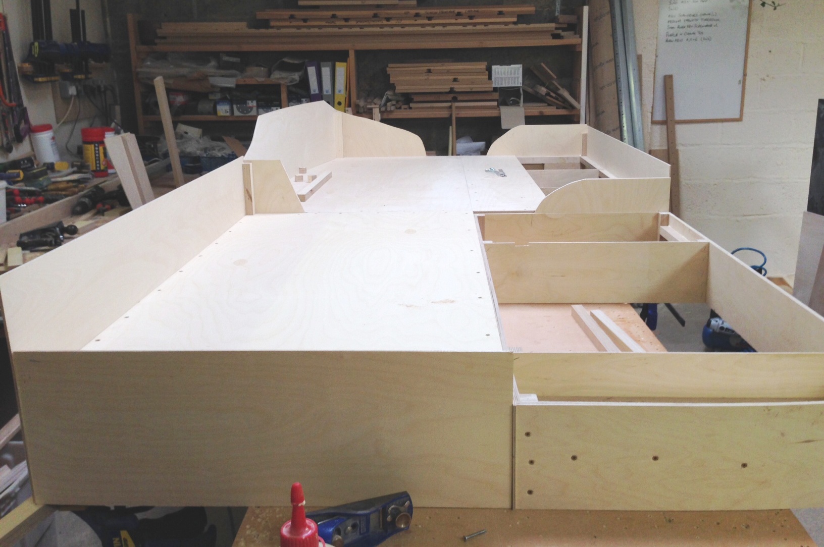
But the acid test of the new boards is shown in this view. On Portchullin one of the problems is that the boards rise up slightly at the joints – a problem I see a lot on layouts. This is dead flat; so we won’t see the trains doing any Casey Jones runs over the mountain ranges!
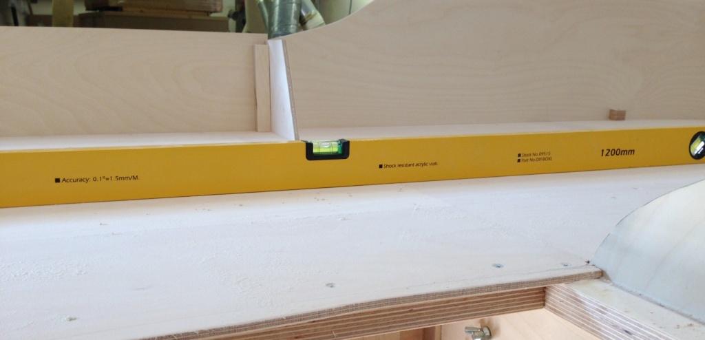
The next visit will get on with the last two boards, which will take up the rather obvious space where Julian is working. These will only be a single width in size as the boards are tapering in to 700mm wide at the end on the left in the view below. To give a sense of scale, the yellow spirit level is 1200mm and the dark one 750mm. (see Mr Ullyot – two spirit levels now………..)
So thanks again to Tim & Julian and if any of readers are looking at electric loft ladders; give them a call. S&T Joinery.
Baseboards coming along……….
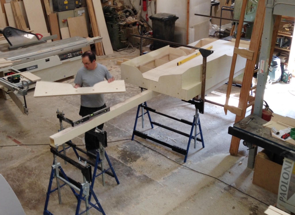
Tim and Julian’s business has been doing rather well so far this year, which has meant that they have not had time to accommodate me at their joiners shop and hence baseboard construction has been slow. However, I did manage to get down today and we have got the first four boards quite close to finished.
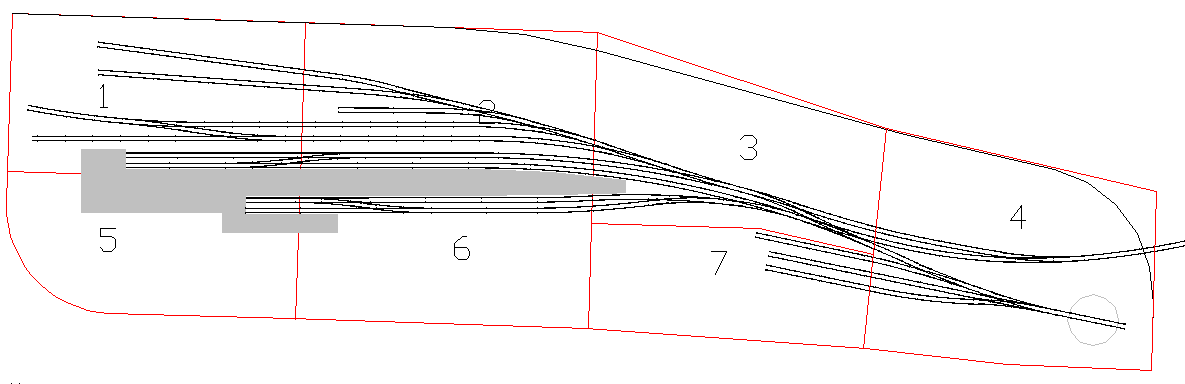
This view will look straight at the train shed, with the bay to the right (it does come onto the nearest board; this is a bit not yet done. The remainder of the platforms be to the right and the goods yard will be behind the trainshed/platforms. If you want to be reminded of the trackplan, it can be found here or here.
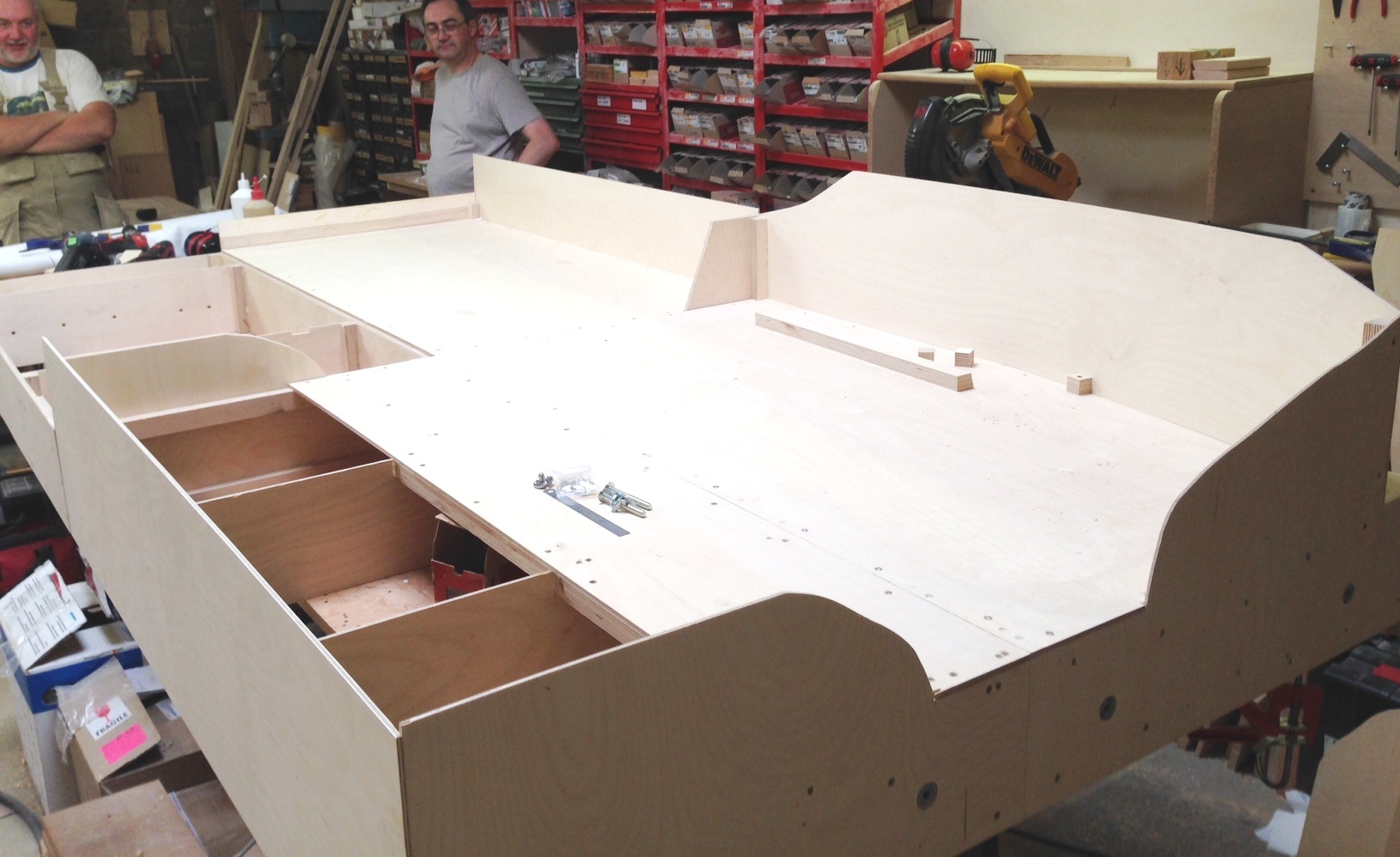
Tim and Julian look on the four boards and give them a comparison for size. The overall depth is 1200m deep and the length of the boards in visible is 2.6m. This view would be from the bridge (see the trackplan links), looking back over the yard and the end of the platforms. The ground will be raised here, but falling away to the left.
A view from the buffer stops, well it would be but you wouldn’t be able to see them for the end of the trainshed. The ground will slope down substantially to the right and be above rail level to the left.
I hope to get these four boards finished in my next visit and also the beams that they will sit on (and will be attached to the legs already made).
A new website for Miscellany Models
I will be making at least some of the items that I have been developing available for sale.
Therefore, I have set up a separate website entitled Miscellany Models that shows what is available, how to get them and (when I get some time to do it) will become a repository for prototype information that I have on the items I have made, construction/finished photographs and instructions.
You can find this website here. If you look hard, you will see some hints as to what other things I have been working on and are expected to be made available in due course.
