Blog Archives

Still Swapsie – A Signal for Nampara for Hendrawna Part 2
Having assembled the basic post and ensured that it was working, the bolts can be filed away and we get to the following stage.
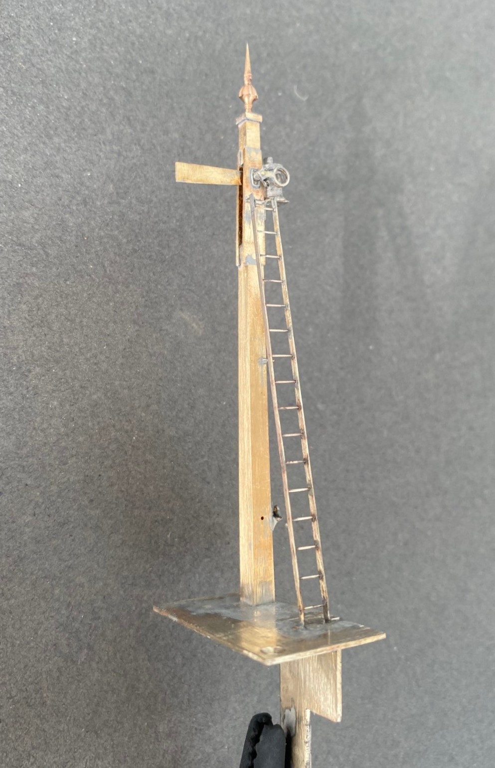
The spectacle plate plate is rather unusual in that it only has one lens which isn’t available via any manufacturer and the arm is notably shorter than I am used to so I had to etch these to suit. Although I could not find a lamp that matched what was on the prototype, I was able to modify a MacKenzie & Holland lamp from MSE to suit. Thereafter, the remaining assembly of the signal was fairly unremarkable.
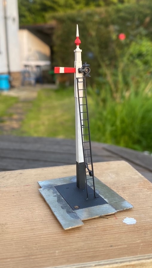
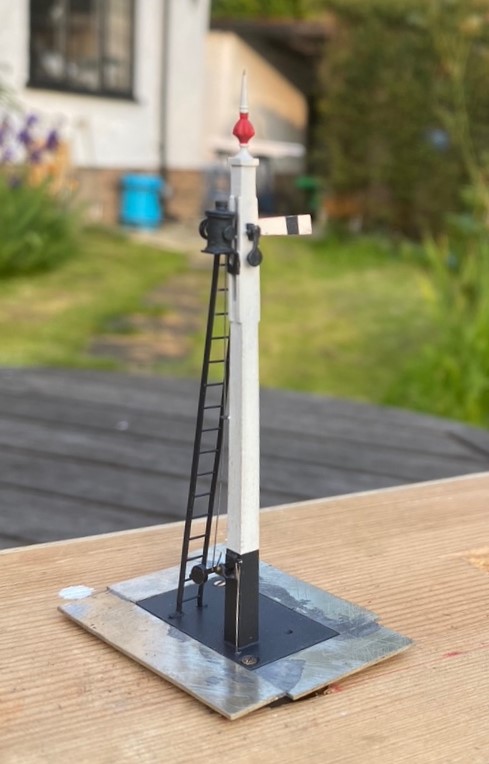
And then once it had been painted, including the unusual red highlighting on the finial that I rather like:
And of course we must have the obligatory video to show that it really does work!
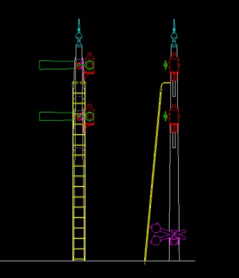
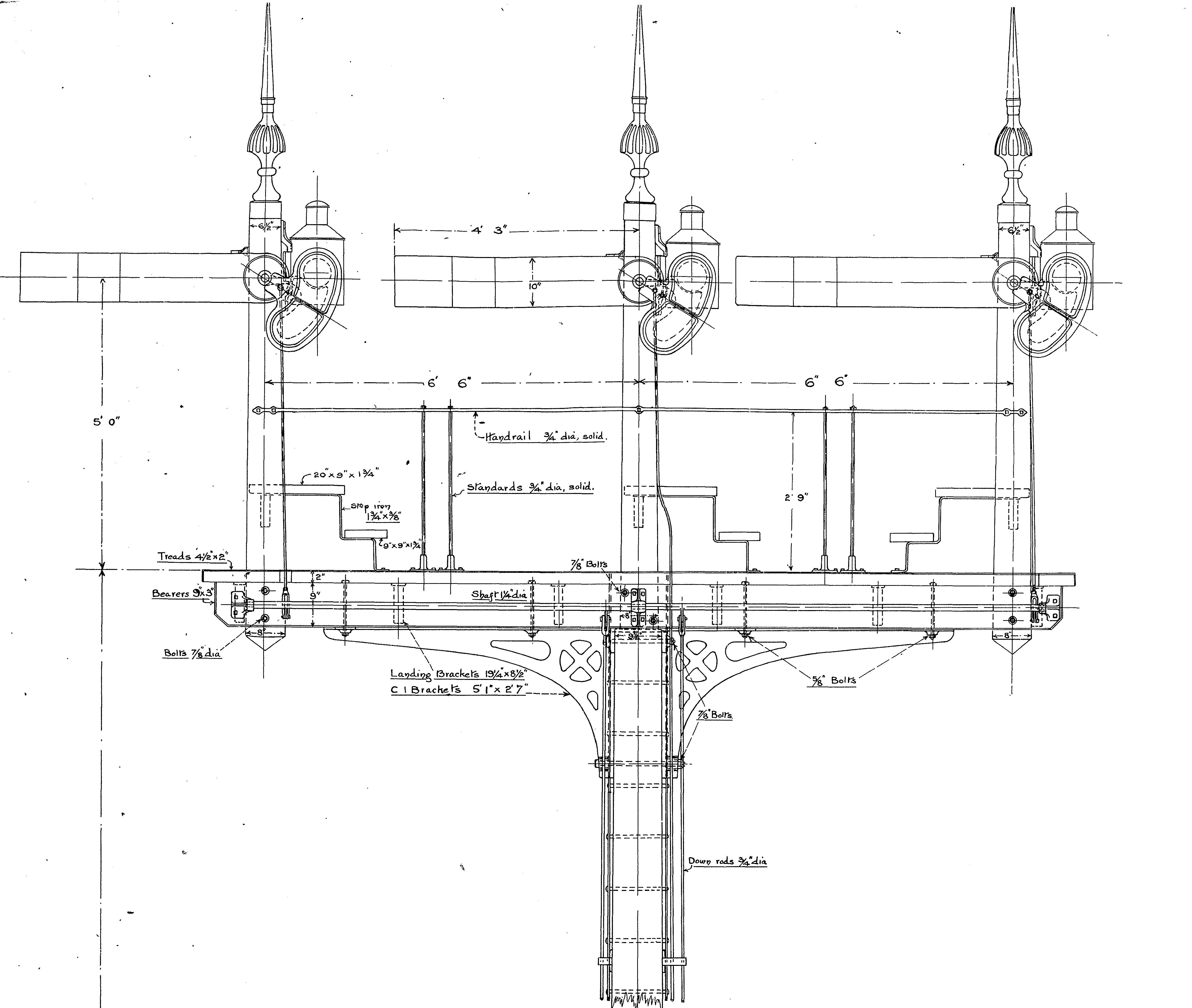
And for those of you that might want it, this is the drawing of the signal, which has two arms, at Didcot.
Swapsie – A Signal for Nampara for Hendrawna (Part 1)
Swapsie – the childish act of swapping things according to Wiktionary.
Do you remember at school swapping a Top Trumps set for a the latest Hot Wheels car or similar? I do! I remember getting roundly b*llocked by my mum for not recognising the value of things I was giving away and (metaphorically I am pleased to say) swapping gold bars for glass beads almost like the Incas and Cortez.
In the world of toy trains, the same happens and is very useful where someone can offer something that you don’t have (or find difficult to make) in return for something you do have. This is one such example. Sitting next to Duncan Redford at an EM Gauge Society/Scalefour Society skills day a few years back demonstrating signal construction a barter was arrived at whereby I would build Duncan a signal in return for him doing some 3D design and printing. I think it is fair to say that neither of us have rushed with our respective shares of the bargain but with the next ExpoEM only a week away, I have shifted into gear to finish the started signal that was my part of the deal.
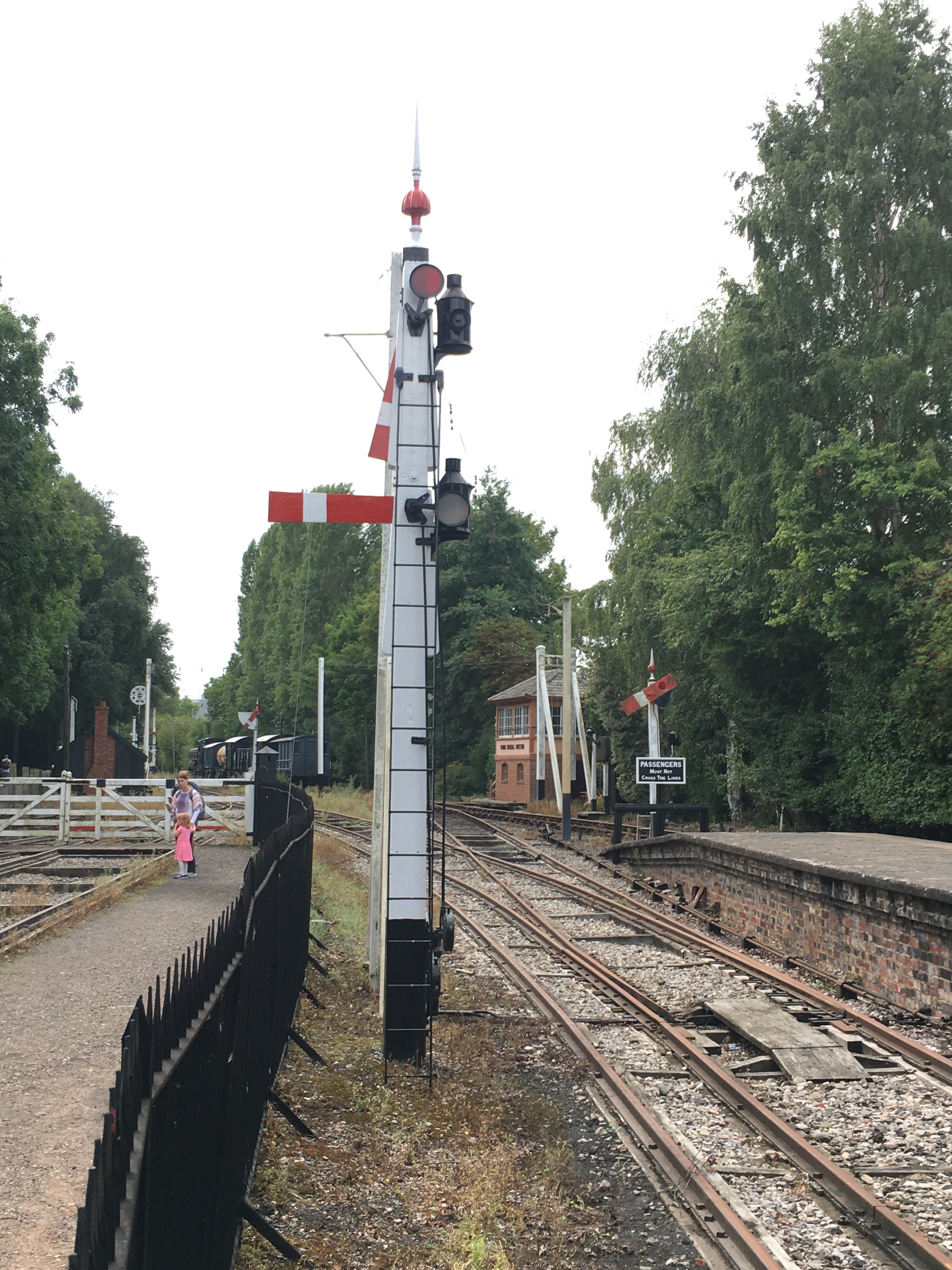
Duncan is building a GWR broad gauge era layout and wanted a close replica of a signal that the GWR Society has recreated at Didcot, but adjusted to have only a single arm. So after coming out in cold sweats about the idea of modelling anything GWR (!!!) I took a look at it. Like many signals, there are differences and similarities with other signals but after a bit of study it became clear that it was sufficiently different that a site visit to Didcot to be required.
Having measured it up including, when no one was looking, a climb to the arm/lamp to measure it, I came home to draw it. I was shocked to find that it was tiny; 3mm/1foot at best and I had a panic attack -had I mucked it up and mis-measured it. Obviously, being a professional surveyor I could not possibly have done that, could I? After a few months, the fear that I had niggled on me and so came about site visit number 2 and a further climb up the signal ladder. Nope, it really is tiny – both the post and the arm are notably smaller than I am used to.

There are several unusual aspects to the signal; the one glass spectacle plate, the tapered arm and the very pronounced stiffening around the slot in the post were all going to be key to capturing the character of the signal. So out came the computer and a small fret was added to an etching order for the arms/spectacle plates. I then formed the basic post from 4mm square section brass which I filed to a taper with a 2.5mm cross section at the top.
Despite having built a few slotted signals already, they are still pretty difficult to get to work well. The difficulty that I have had is to get a soldered joint onto the arm spindle when it is encased in the brass post around it that acts as a heat sink. On a number of occassions the joint has broken and the arm no longer operate. I was determined this was not going to happen this time and have adotped a different approach, by assembling the arm first and then mounting it within the post whilst this was being assembled.
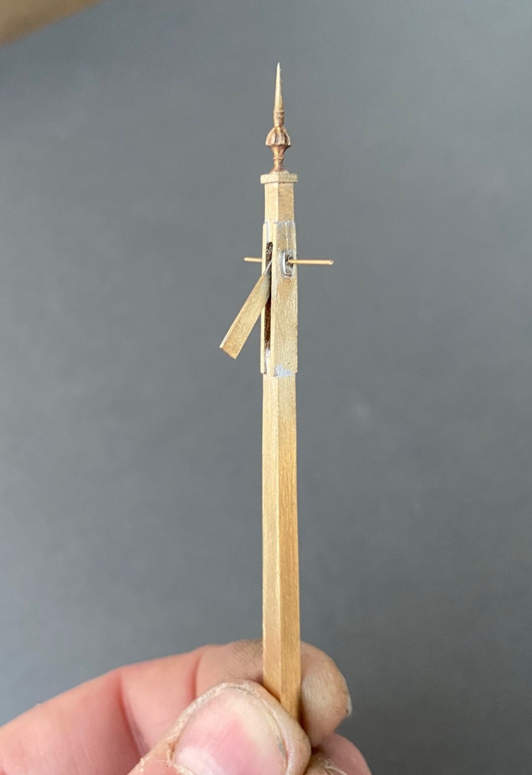
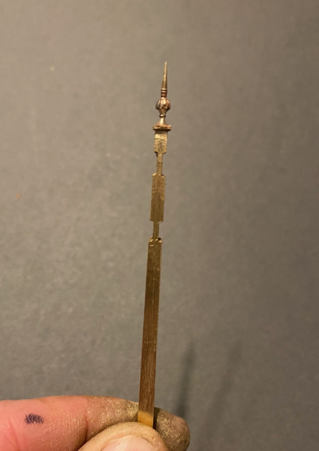
I had filed some 4mm square section into a taper to form the full length of the post. Even though I was about to cut a section of this out, it is necessary to form the full length of the taper so that it is consistent across its full length. Once I was happy with this, i filed two pairs of slots in the outside of the post on oppposing faces. The depth of these was such that the tongue between them was the correct size for the slot in the post. I chose to mount the finial at this stage, with some 296o solder and a lot of heat (from a minature blow torch). This is what it then looked like:
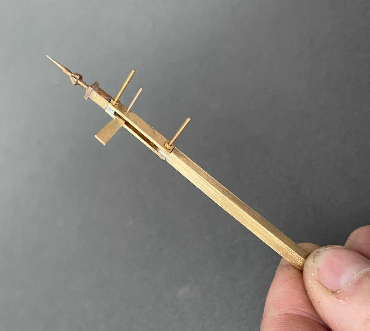
Next, I cut away the block of post that sits between the two filed sections to create a hole in my post. As there is around 2 hours of work to get the post to this point, it is a bit nerve racking chopping it like this! I then cut a pair of 1*4mm brass plate lengths to sit on the tongues and drilled both to receive a 14BA bolt. This was threaded through the first of the plates and adjusted until this a continuation of the taper of the post – this entails some filing of the metal to make the outside face match the post and plate match. It was then soldered in place, again using the 296o solder and a blow torch, to look like this:

The photograph above shows that these plates were wider than the post, in practice the prototype acheived this by planting timbers across these sections but it is easier to do this by way of using the sider plate material.
Temporarily mounting the second plate enables the hole for the arm spindle to be formed through both parts of the arm. The arm was now attached to the spindle with more use of the 296o solder and the use of a couple of minature washers either side of the arm so that I could be confident that the joint would hold.
Releasing the second plate now allows the arm/spindle assembly to be inserted and any adjustments made to ensure that it can move freely in the slot by securing the second plate in place with a 14 BA nut. The nuts and bolts are scarificed in the build by leaving them in place for the next step because once I was happy that it was correct I soldered the second plate in place including the nuts and bolts. This time I used 145o solder which meant that it would not disturb the first plate as I was doing this and this is what it then looks like – a slotted post with an arm within that is firmly attached to its spindle!
More to follow; including the second piece of bartering that I know someone is looking out for progress on!
Only the printable words for this Wednesday!
Hmmmm……..
A signal imitating a Fresian cow was not the effect I was after…………..
Halfords etch primer is obviously not that etchy!…………….. So someone will be waiting a tad longer for their signal than I thought…………
Tatty’s Top Tips – Signals
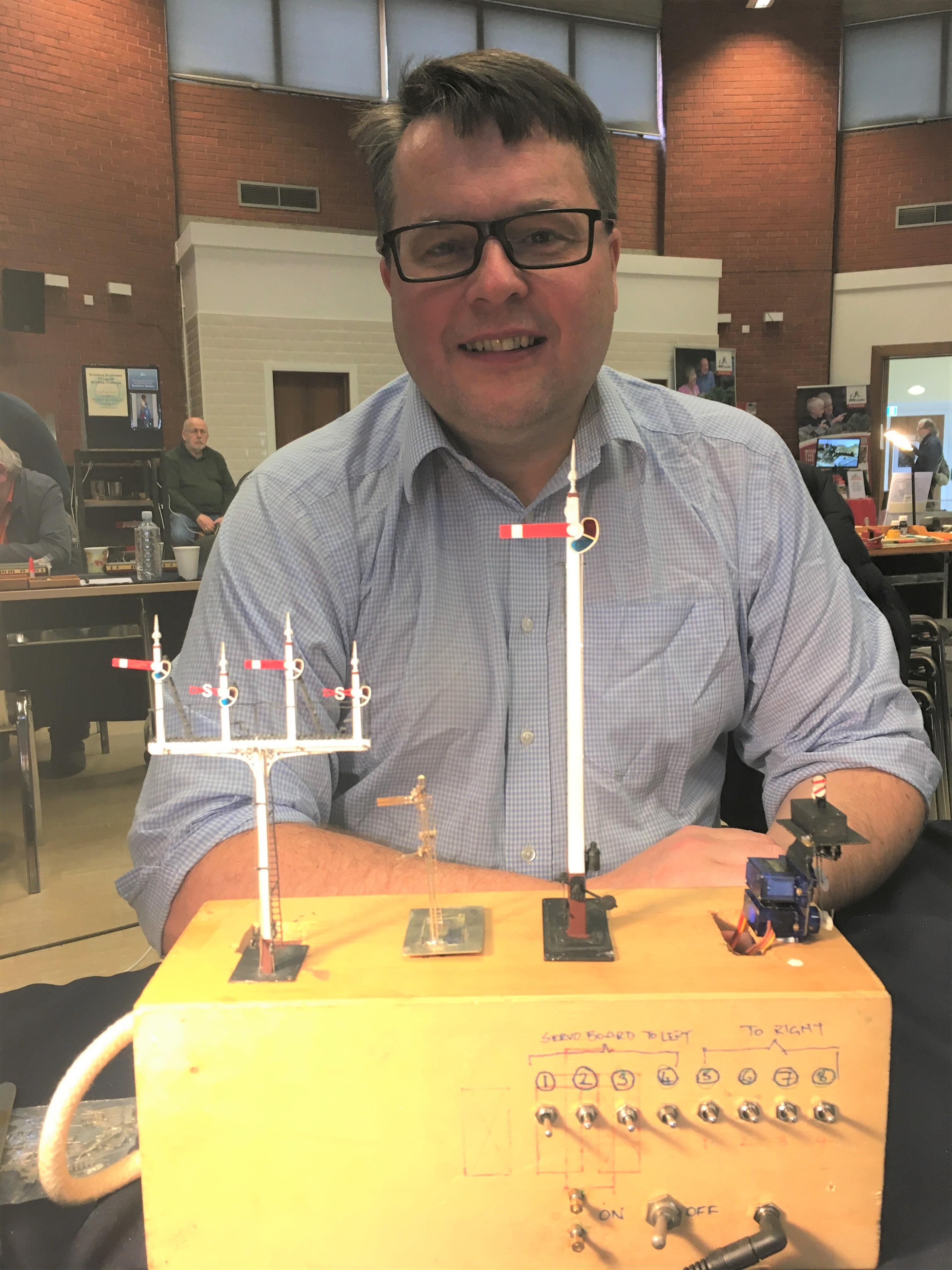
A mere three weeks ago, but a lifetime in the past now that we are in the middle (or more worryingly, perhaps just the beginning) of the Covid-19 crisis, I was a demonstrator at the joint EMGS/Scalefour Society skills day. These skills days are not really exhibitions and are instead aimed at passing some skills on to the visitors – thus they are primarily a hall full of demonstrators with only the odd layout or two to break up the rows of desks.
Here I am, in a shockingly creased shirt (!), and as you can see, I am demonstrating signal construction. I am pleased to say that at the skills day I had a solid stream of people engaging with the topic all day; so much show I had to pull down the shutters for a brief lunch as otherwise I really would not have stopped all day!
By way of preparation for the event, I thought about what I have learnt about building signals and distilled a list of my top tips. These proved to be the cornerstone of my conversations with people at the Skills Day so I thought it was worth repeating them here on the blog.
Planning Ahead
- Conceive how you are going to mount the signal; where and how, what is above the ground or below the baseboard – which might well mean you also need to;

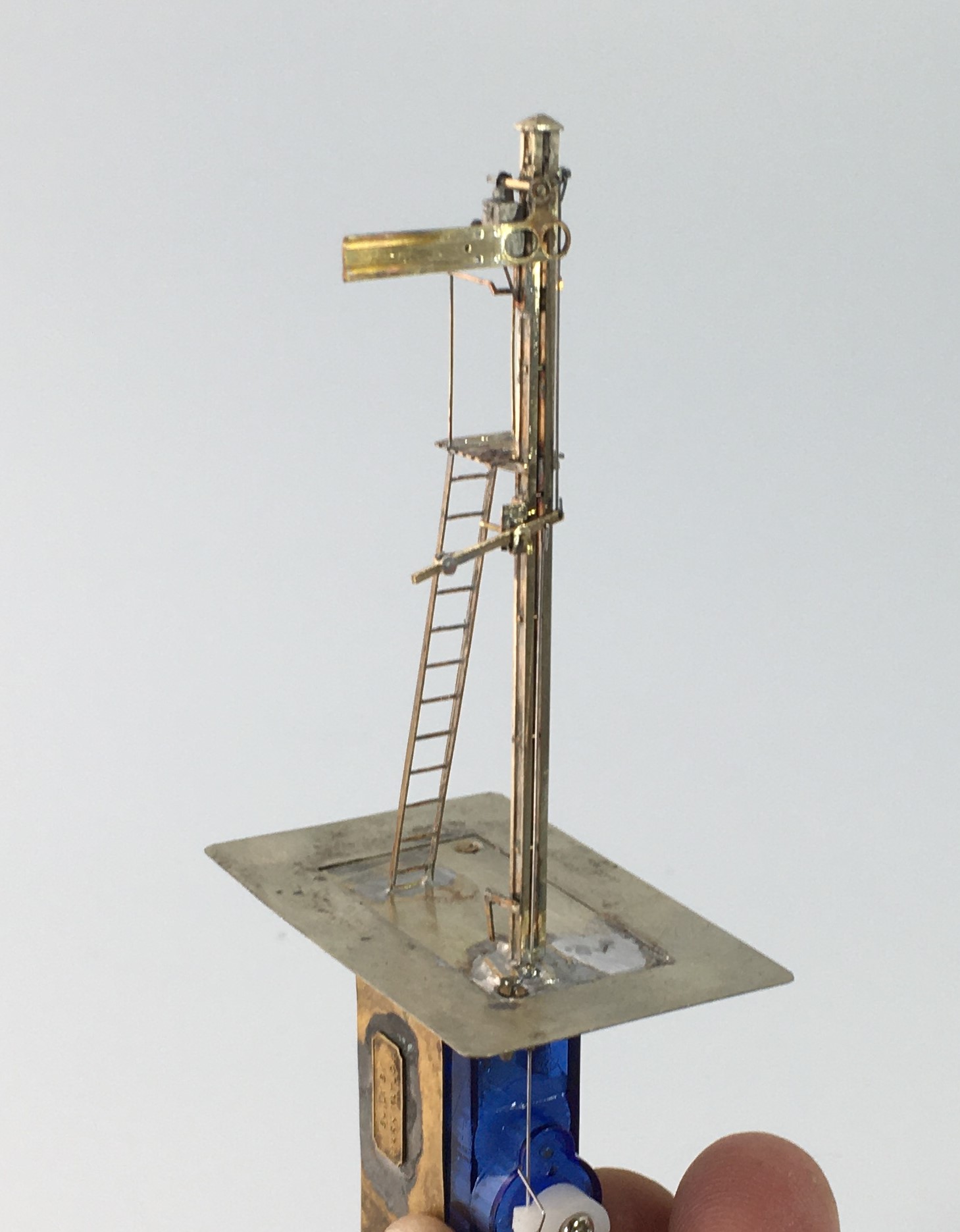
The base and mount for a two movement servo controlled signal
- Decide how you are going to operate the signal, how is the drive mechanism to be mounted and what does it need to be connected to mechanically/electrically;
- If you are going to illuminate your lamps, you need to decide how you are going to run the wires to the LEDs or fibre optic cable. It is possible to use the post as a common return but you still need one wireway;
- Consider how the movement is to be transmitted (especially bracket signals) and how you are going to replicate this? Multiple movements in close proximity to each other can lead to interference, compromises to reduce this risk are sometimes desirable (especially for triple or more movements in close proximity);
- Conceive how you are going to paint and assemble the signal before you start – it is generally easier to paint arms and ladders before you assemble them so it is possible to create sub-assemblies to be attached later – the touching in of local areas of damaged paint caused through assembly is a small price to pay for the ease of painting the remaining areas;
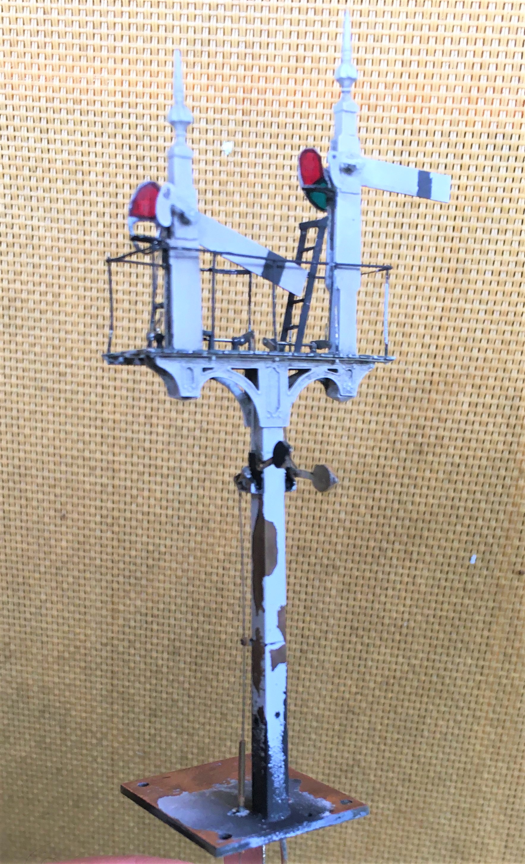
A Southern rail built home signal; the post was formed of two pieces of nickle silver rail.
Construction
- Tight, tight, tight – the most important part of building a signal is to keep all holes of operating parts as tight and snug as possible as slack leads to sloppy movement;
- You will use a lot of fine drills, down to 0.3mm, and a good quality pillar drill will mean you break rather fewer of them!
- Use the file up the length of the post not across it as much as possible – the files leave less scars and any that do occur mimic the grain of the wood;
- Pre-form or pre-drill elements such as balance weights, holes to the posts or landings early on before they are assembled when it is easiest (well potentially!);
- The prototype of most of the components to a signal are pretty delicate with fine sections; thus, to capture their character these needs to be similarly fine, however:
- There is a trade-off to make with the operating components such as balance levers which are typically best made over scale and with laminated brass to give them more strength;
- Generally, build the bigger more robust elements first and potentially alter the build sequence in the light of thermal mass and whether adjacent items might be disturbed by later additions – consider using different temperature solders and prefabrication of elements such as dolls with all of the lamps/landings finished;
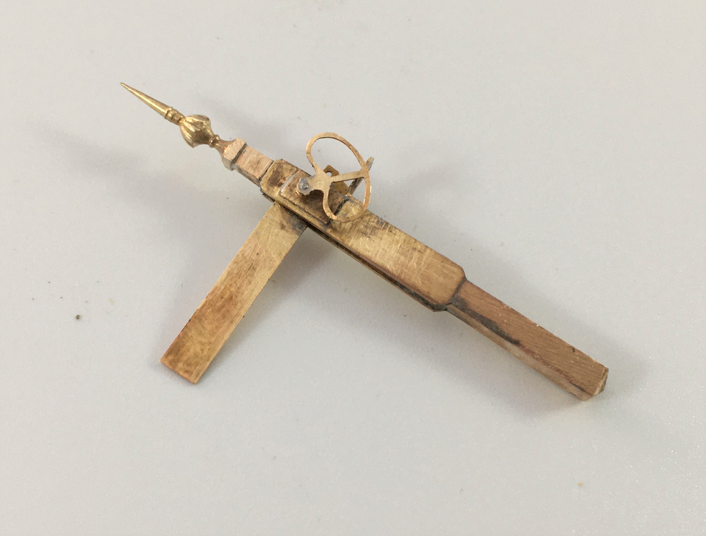
A prefabricated doll and arm – I wouldn’t normally fit the arm until after painting but this is not true for slotted post signals
- Don’t use the flat etched ladders, they are too flexible to look real. Either use the built up versions or solder 0.3mm wire on both front and back of stringers and file the outside face flat – they look more realistic and are more durable.

A flat etched ladder with 0.3mm wire being soldered to the stringer
- Lots of delicate parts and complicated sections means that ultrasonic baths are really helpful for cleaning without damaging elements;
Slotted Post Signals
- Not the easiest because of the need to solder the arm to the spindle inside the slot. Use a laminated piece to the ear that is the point at which the operating rod attaches to the arm and extend it cross the back of the arm by 3mm so that it is would project beyond the slot slightly. Be liberal with the solder but make sure that the rubbing faces are cleared of any excess. Wrap the arm in cigarette paper and insert it into the slot. After the spindle has been inserted, touch the cigarette paper with light oil and allow it to soak through. Then put a little flux on the laminated ear and apply the iron. The heat will transmit along the solder joint and reach the spindle.
Operation
- Protect the signal from excess throw; they are delicate – therefore set the servo up to an approximate centre point through before connecting it to the model;
- Leave room to be able to see the signal as you are setting it up, otherwise it takes ages and a lot of bending under the baseboard;
- If you are going to illuminate your signal, understand what the right colours would be – oil lamps are relatively dim (so you need to resist down the voltage) and quite yellow (so modern LEDs need to toned down).
Dimensions
Dimensions were not standardised even within a company, let alone between, so offering directions on dimensions is dangerous – all I will say is these dimensions are commonplace:
- Single post wooden signals – 6” square at the top and then tapering out 3/16th of an inch for each foot of height (1.5% or so)
- Wooden doll posts – 7” square at top and tapering as before
- Main post for wooden bracket signals – 10” at the top and then tapering as before
- Single post tubular signals – 5 1/2″ to the upper portion and 6 1/2″ to the lower portion. The height of the lower portion varied with the height of the post (for details, see LMS journal no 4)
- Arm – centre pivot – 1′ 6″ from the top of the post; second arms 6′ 0″ below that;
- Spacing between dolls – 6′ 0″ or 6′ 6″ (less for shunt arms)
- Height of handrail to landings – 3′ 0″
A GER three doll bracket signal
