Blog Archives
Slips, Moans and the Third Way
A while back I outlined the struggle (that may have been largely in my head!) with wiring the single slip into the MPD. After some frantic reappraisal of this as the layout was being set up at Scaleforum (thanks Chris!), it was fully operational.
Given this is a further blog post on this slip, you can tell there is a but……….. In this case it was that route setting the turnout such that it was electrically correct was not intuitive. The difficulty lay in the straight through route – to set it electrically for the route through on the main required a different arrangement of the switches to that for the straight run from the loop to the MPD. This was even though the physical route setting could be exactly the same, so it become quite confusing! Not having a power district breaker meant that the layout locked down rather too frequently as a result.
Although I don’t see it myself, the guys think that one of my main operating crew has a bit of a reputation for being a moaner when things aren’t as easy as they could be…… With this in mind, it is clear that I have to do something about this to keep the peace. In addition to the use of LED route identification lights on the control panel, I have found a third way of powering the crossings on the slip. Its this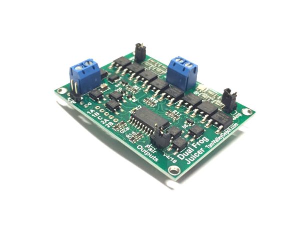
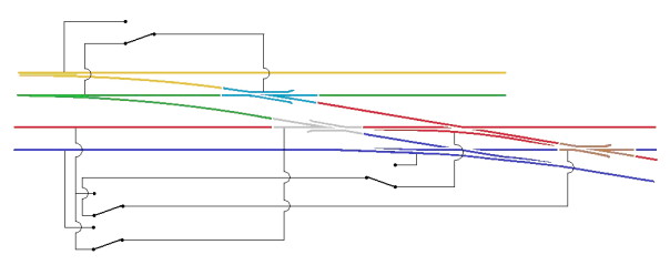
This is a frog juicer (apologies for the Americanism!) and is simply a device that detects a short-circuit when a vehicle hits the crossing. Instead of tripping out (as a power district breaker would), it swaps the polarity. This happens faster than a circuit breaker can trip or the locomotive motor react so can be relied upon to switch the crossing without any visible effect on operation.
The net impact of this is that my slip only needs to be set for the route that is being used. The crossings will not be changed by this route setting, instead as the first wheel touches each crossing it gets switched to the correct polarity.

Slip Ups – There is an Easier Way……………
My last post recounted the difficulties that I was encountering correctly wiring up a slip and the technique I had arrived at to overcome this, This precipitated various bits of advice including an alternative approach provided by Richard.
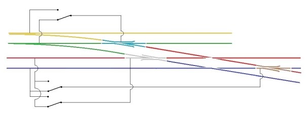
Richard’s solution is certainly a little easier than my approach to wire and does not need an additional point motor to run the extra switching required. It is, however, slightly less idiotproof in use than my version – this is because once the approach turnout is set for the branch in my version, the whole of the run was also set electrically. On Richard’s version, it is also necessary to decide whether the main line to yard is to be set for the yard.
This is what it looks like as a wiring diagram and it is important to note that the approach turnout (A) is also operating one of the slip’s switches too.
I need to fire up the soldering iron now and undertake the correction, so that we can play with trains!

A Bit of a Slip Up…….
I have been continuing with the wiring of Glenmutchkin, but have hit a snag; one that I should have been ready for – the wiring of the slip, I had been aware that a diamond crossing was a challenge to wire and I was suckered into thinking that the switches on a slip could over come the challenge, Well I go that wrong…….!!
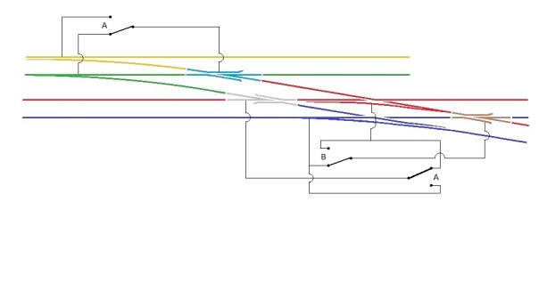
The basic problem is that there are a choice of two routes through a diamond crossing and each route requires the polarity of the crossings to be different. The diagram below, which shows how a diamond crossing needs to be wired, should illustrate the problem. The only solution to this is to power the crossing polarity by way of an approach turnout – if you really don’t have one to set the polarity with, then you are going to have to resort to some switches – but at least it will give you a good excuse to interlock the diamond crossing with some signals to remind you on which direction it is set!
Hopefully this is clear that the crossings on the diamond crossing are activated by detecting the direction of the switch on the approach turnout. If it is set for straight ahead, then a train can’t travel over the crossing and therefore the parallel line can so the polarity of the crossings are set accordingly. Conversely, when the approach turnout is set to the branch, the line across the diamond can be used and the polarity is set to suit.
The principal with the diamond crossing needs to be heeded when the crossing is replaced with a single slip as I have, but it does get more complicated because the switch of the slip can also lead to a different route through the crossings. The crossing to the left of the slip is the more straight forward as it is only activated by the approach turnout. However the right hand crossing is more complicated as if the approach turnout is set for the branch then it always needs to be in the red polarity whereas if the approach turnout is set for the main, then it then needs to be controlled by the slips switch.
Hopefully the diagram above shows how this works.
The irritation I have, in addition to having wired it up wrong already (!) is that the approach turnout is on a different board to the slip. To reduce the number of wires crossing the boards, I have decided to simply use a duplicate point motor for the approach turnout located on the same board as the slip. It is expensive but rather more simple than the additional wires.
NB – please see also a follow up post on this wiring arrangement for an alternative approach.
