Category Archives: Workbench (other)

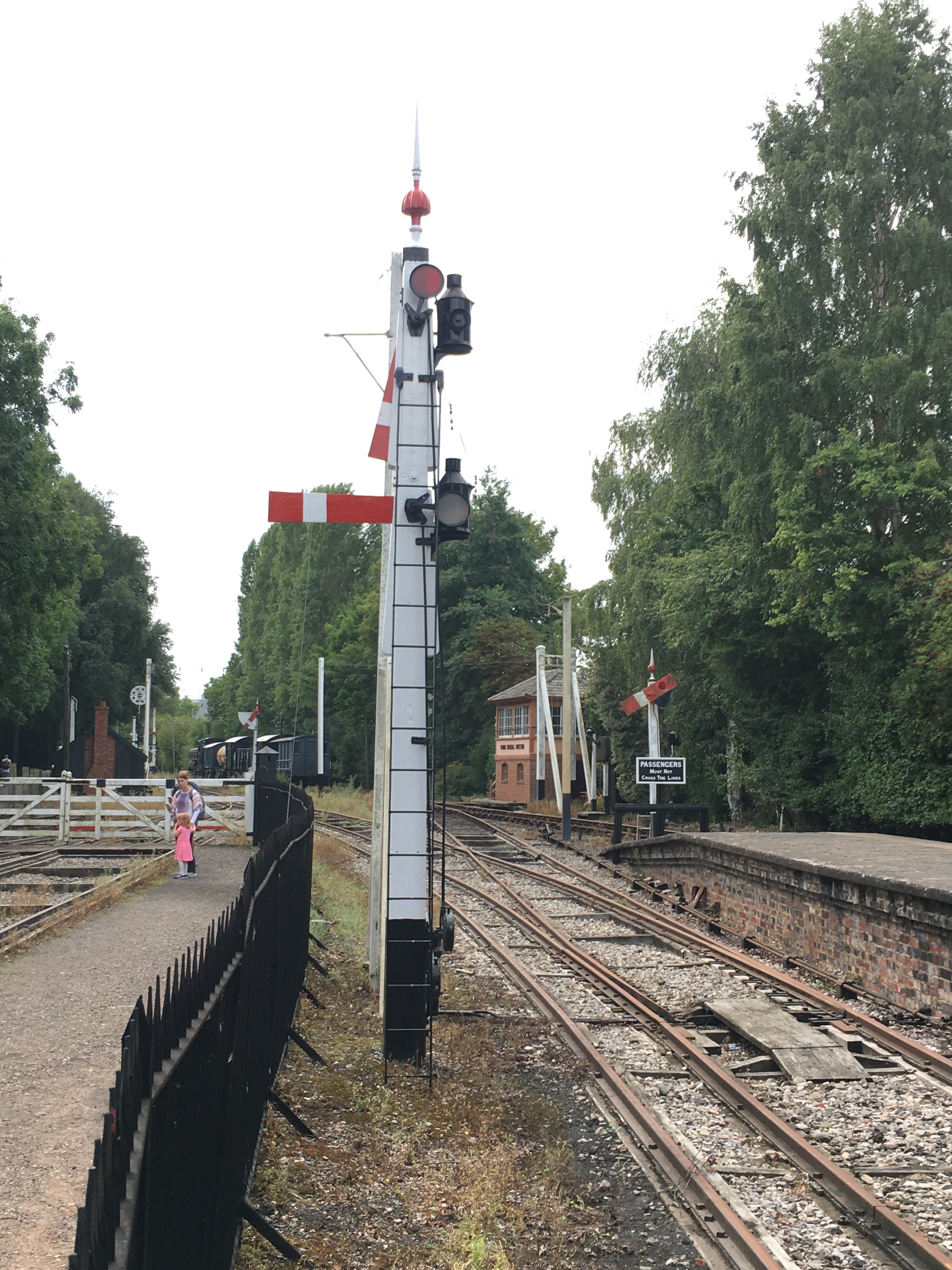
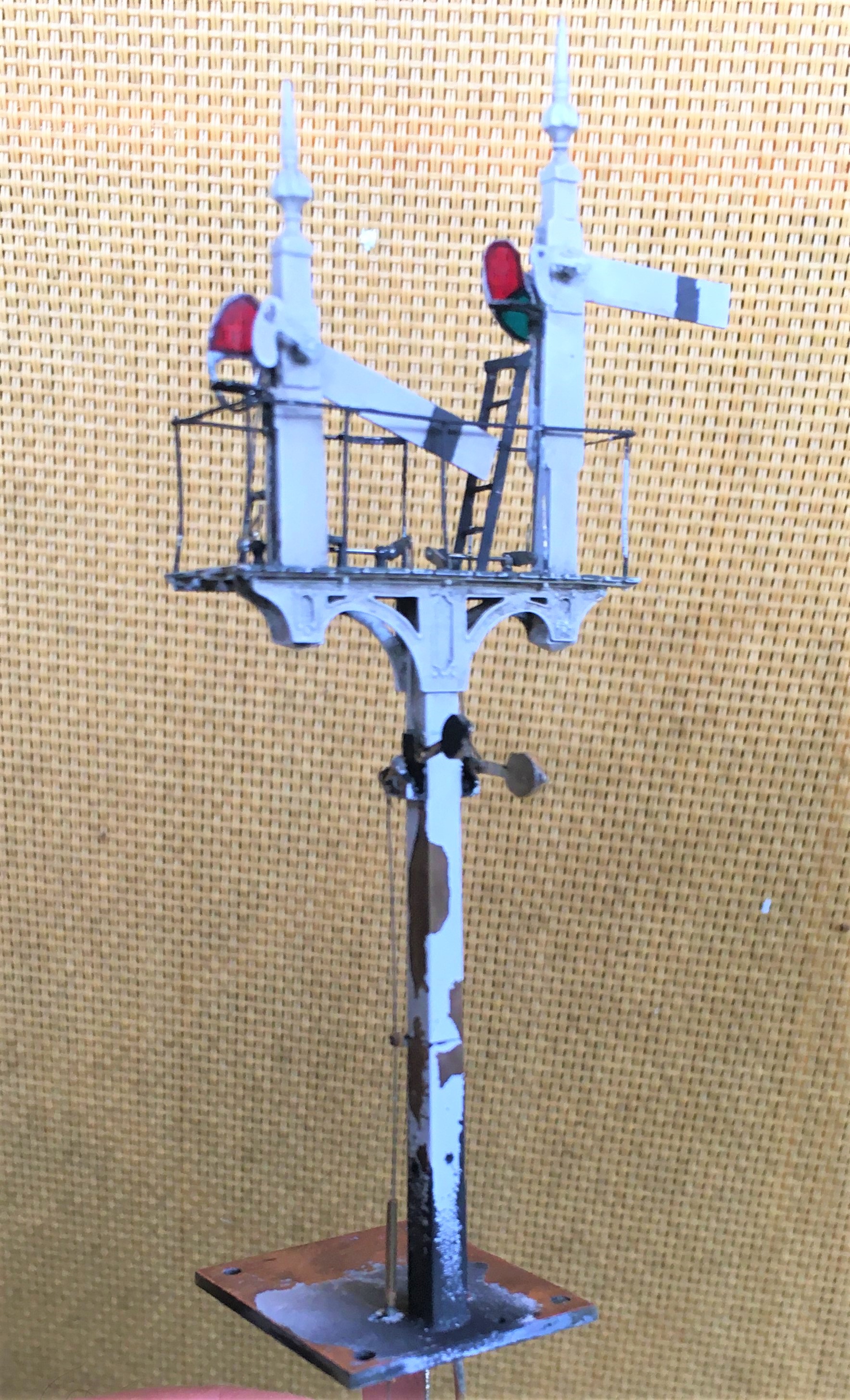
At last, a Finished Signal!
Well, that took a while longer to make than I had hoped! Not least because it is not the only signal I am working on at the moment.
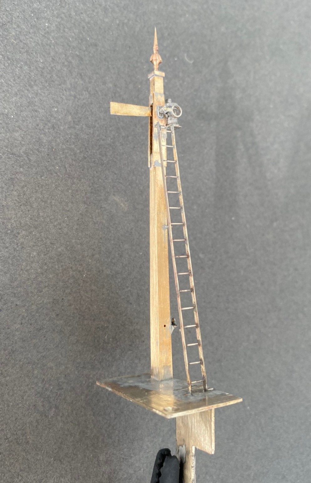
Although the drawing did not show a landing in front of the balance weights, i felt that it was likely one would be provided given that these need maintenance at times. Hence this was formed from some L section and an etched slats and provides a useful point to secure the ladder too.
The issue with signals with dolls is that each doll is in effect its own signal; it has a ladder, arm and lamp assembly. But worse than this is that it is also necessary to get the movement to transfer over to the doll so there is even more than a seperate signal per doll. There are a number of ways the prototype used to get the movement to transfer and in this case the signal uses L shaped elbows. Sadly these are more challenging to make as there are more working components and to be prototypical they out to be little more than a couple of mm in size.
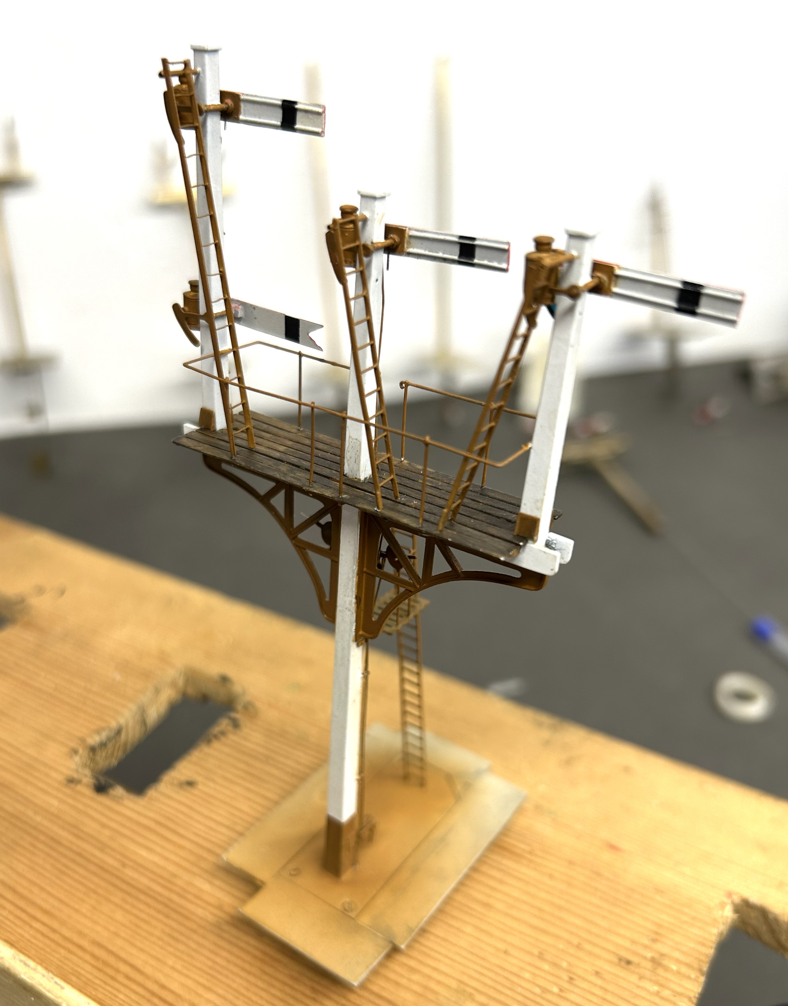
A key trick in making signals is to spray paint as much of the signal as possible. Because the components are generally fine any excess thickness of paint will quickly make the modelling crude. As a result of this, I now generally try to make the ladders detachable. In this case there is a rod attached to the top of the doll that a tube at the top of the ladder slips over, with prongs at the base.
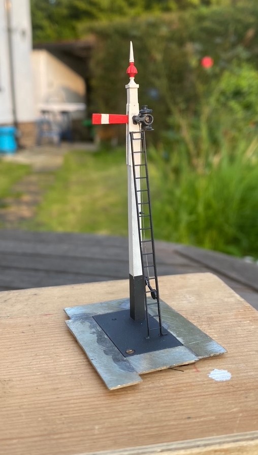
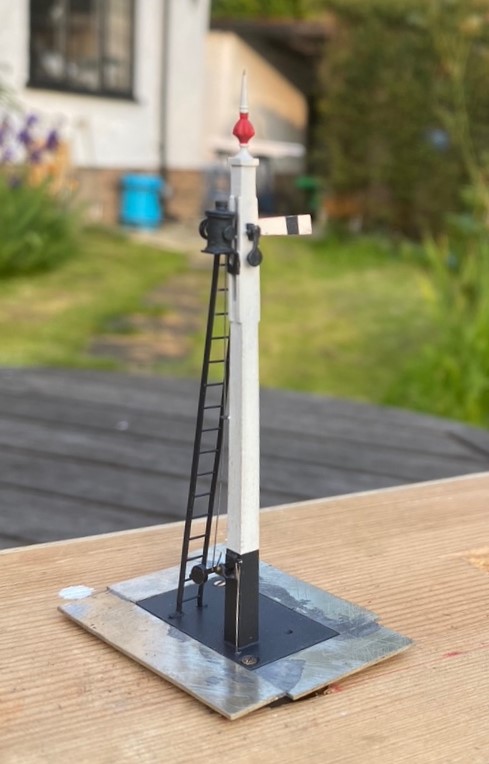
So here it is a finished (except for a tie rod which I fortgot to paint so is to be fitted shortly).
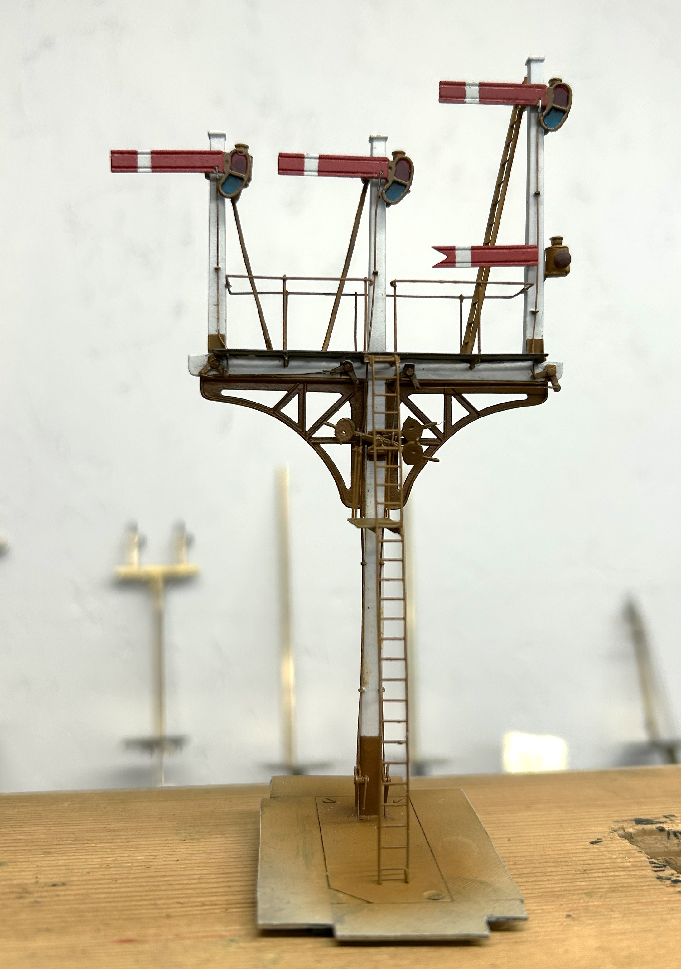
And as is de rigeur for a blog post on the building of signals, here is a video of it in operation.
")
More Seasons Greetings (and Signals)
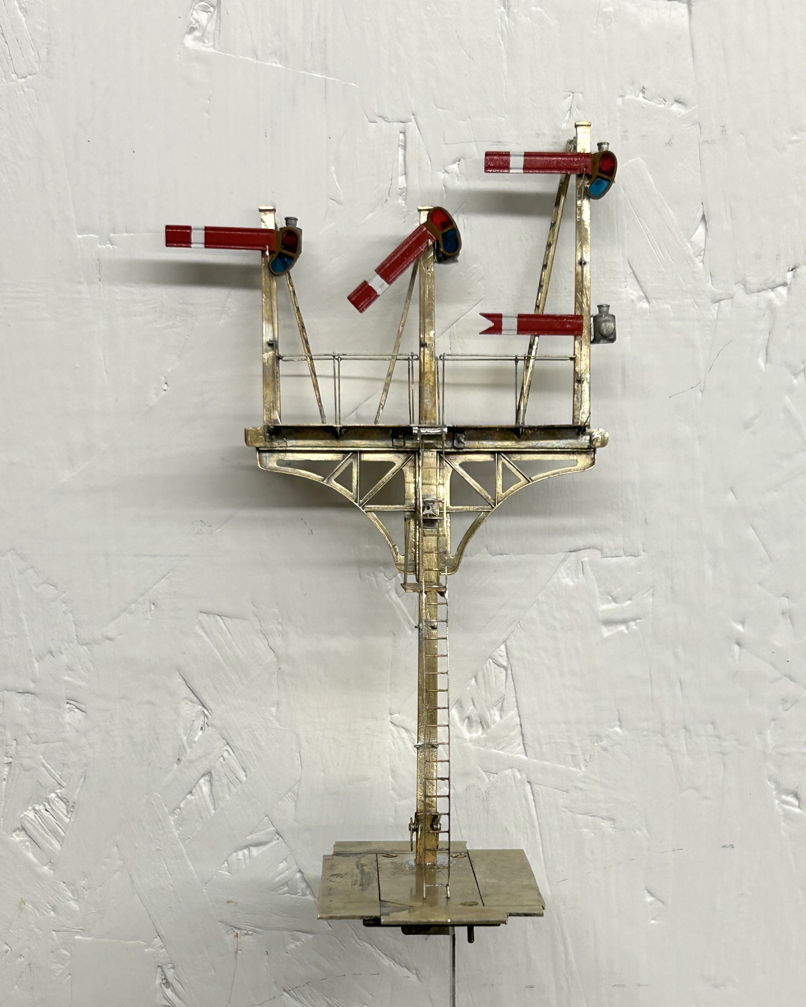
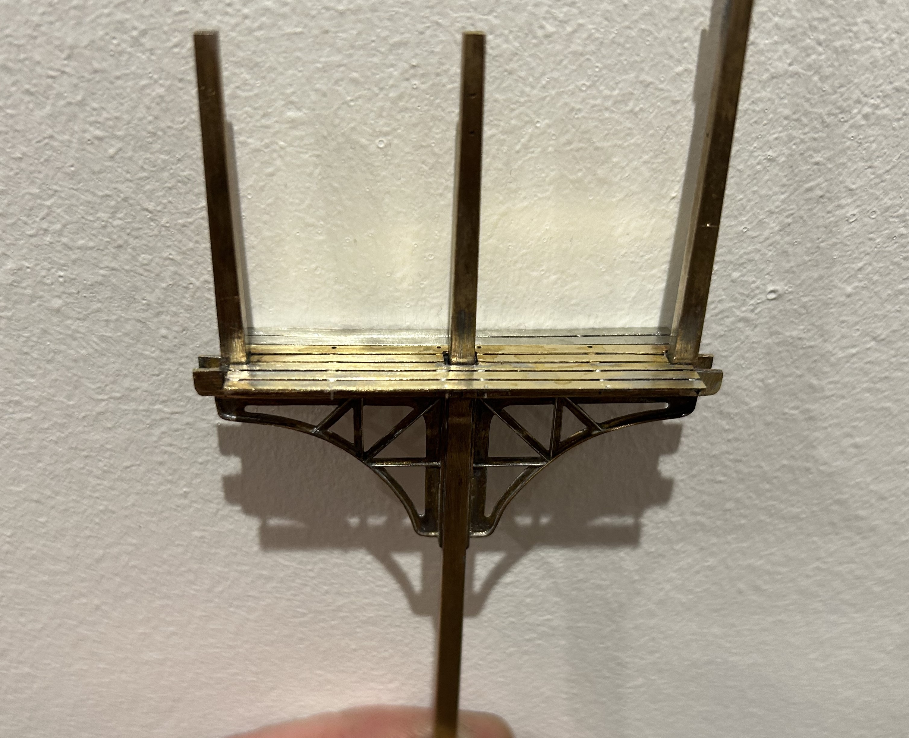
Having got the post and dolls in place, the next step was to fit the brackets.
The LNWR were unusual in not using cast brackets; instead they fabricated theirs from sheet and angle iron. Those supplied by MSE are a flat etch and therefore feel a bit one dimensional.
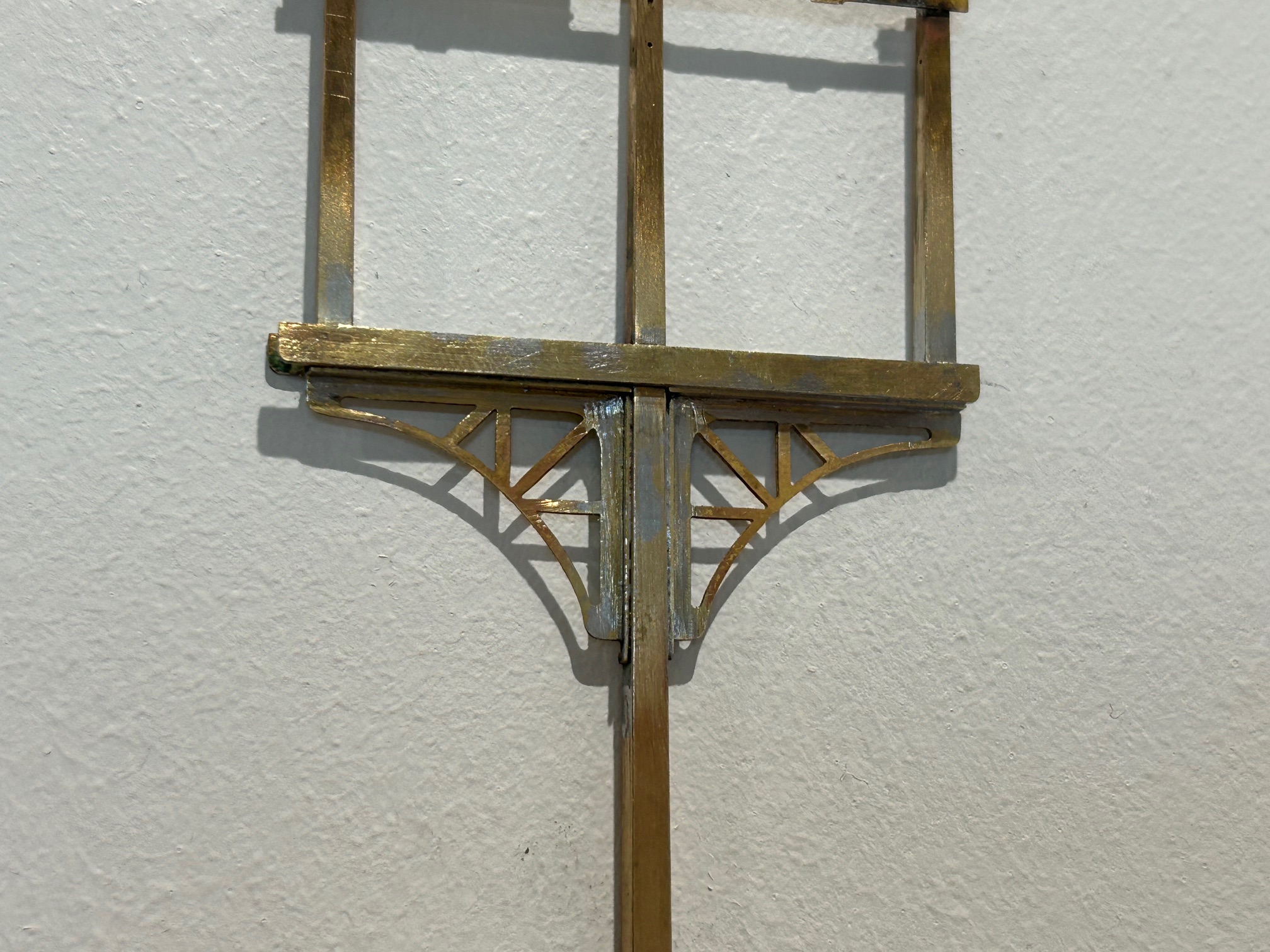
I therefore sweated on brass wire to one side of the strutts on both faces and also a plate on its outer edge. This helps give this a third dimension that was lacking before.

The next issue to be confronted was the landing where the MSE etch only provides a landing to the rear of the posts whereas this (and it appears many other LNWR signals) have landings both sides. I therefore had to produce support brackets and an enlarged area of landing. Foolishly, I forgot to drill holes for the guard rails before assembly, which meant that i had drill them in-situ. This is awkward due to the proximity of the dolls – it cost a couple of drill bits as a result and as a useful reminder to get it right next time!
Next, I diverted my attention to the the mount for the servos. I now always form these with a lower base which is permenantly attached to the baseboard and into which a second detachable base plate is inserted. The two are a tight fit such that once a little scenary is applied to the top, the joint is invisible. These are secured together with 12BA screws to allow it to be detached both during the build and for maintenance but generally it is secured in place. This is because signals are prone to damage when being moved about and would need recommissioning to get the movement correct each time they are reinstated.
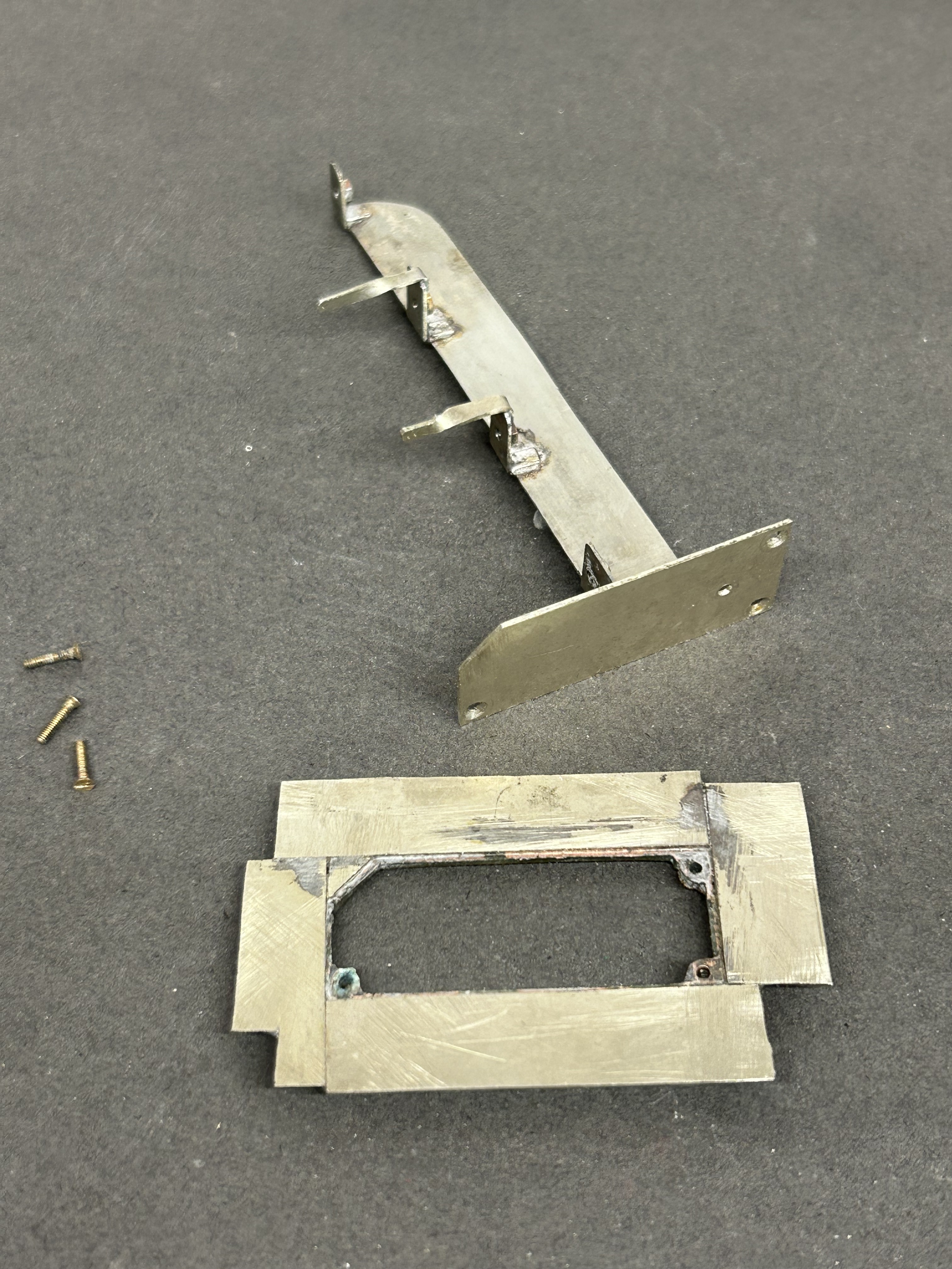
I drilled the underside of the post and tapped it 10BA in order to hold it in place. This enables me to secure it onto the base but subsequently remove it as I build it. I do solder it in place at the end of the build, but the ability to remove it during the build is helpful. The fact that the bolt holds it in place also makes it easier to get the post vertical, rather than trying to hold it vertical simultaneously with the soldering.
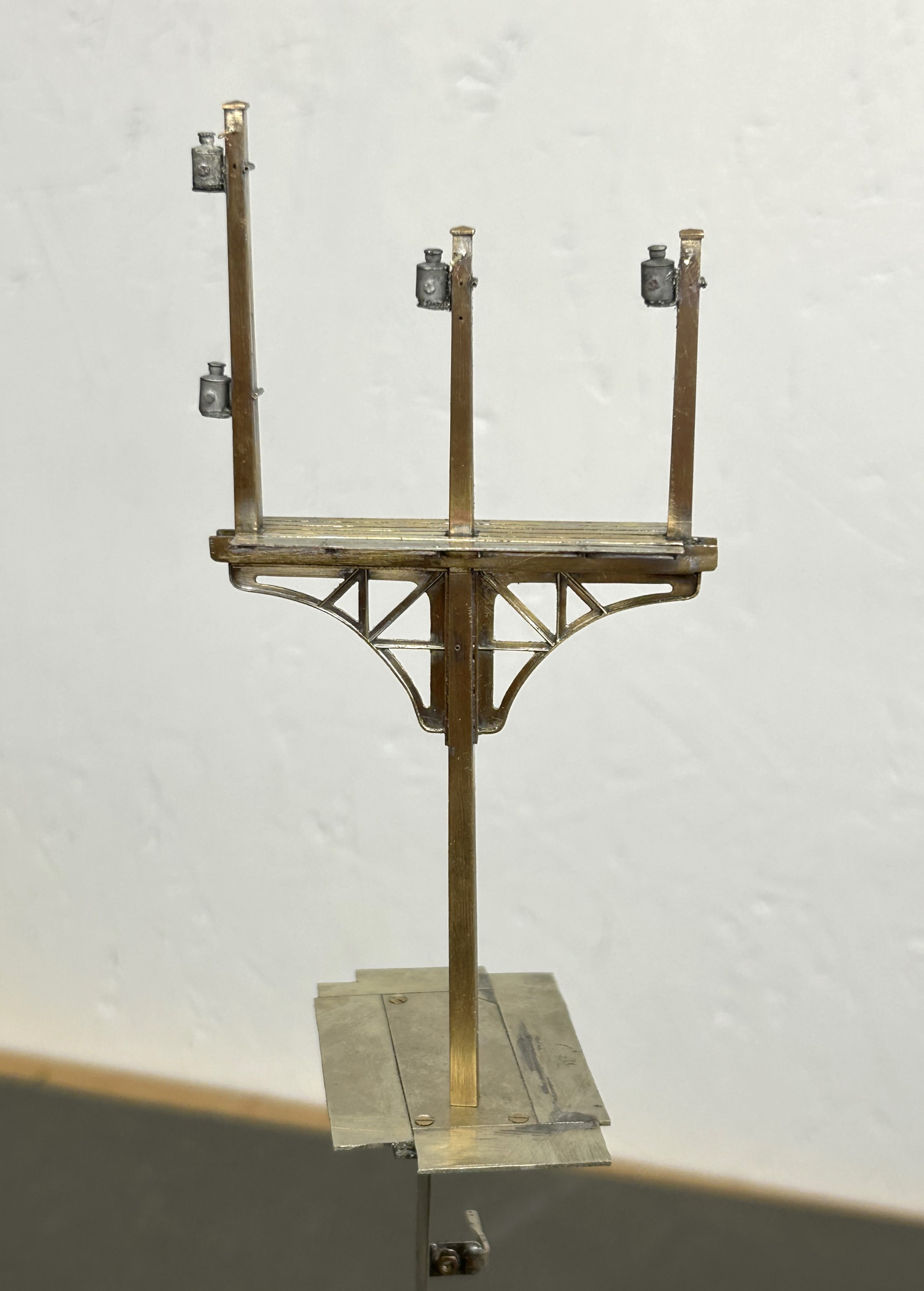
Whilst MSE do provide a white metal casting for the finials, I opted to fashion my own with brass as I find them crisper. To ensure these do not fall away as later tasks are completed, I use a high melting point solder for these and also include a pin drilled into the top of the post. Lamp brackets, lamps, the balance weight mount and some supports for the ladders were next.
I now have a recognisably signal beginning to form but the difficult bit, the movements are still to go.
")
Seasons Greetings (and Signals)
Work (at least real work) is now over for 2025 so I can get a bit of time in for turkey, mincepies and, of course, some signals.
I have built up a number of promises to make people signals; more than enough to keep me fully entertained for not only Christmas but quite a lot of time afterwards! It is time to start delivering on these promises.
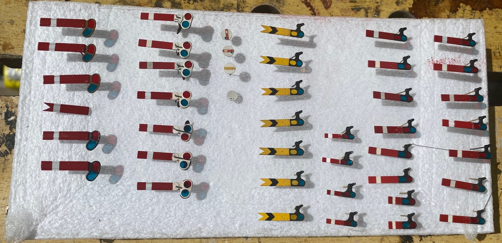
First uo has been to paint the arms. I know do these in advance as there is a lot of effort to paint them well and the best finish is by masking and spraying most of the colours. I can’t seem to brush paint to a good enough standard. I do, however, form the black shevron on the distant signals with black transfers as it is difficult to mask this neatly and the bars on the ground signals are a transfer from 51L.
I should be busy with this lot…………
In another departure, i have borrowed a milling machine to assist me in making the tapered timber posts. I form these from 4mm square brass section, a selection of files and a lot of elbow grease. It is a chunk of work for one signal but I have six taper posts and eleven taper dolls to do – I am not sure i have enough elbow grease to do this many!
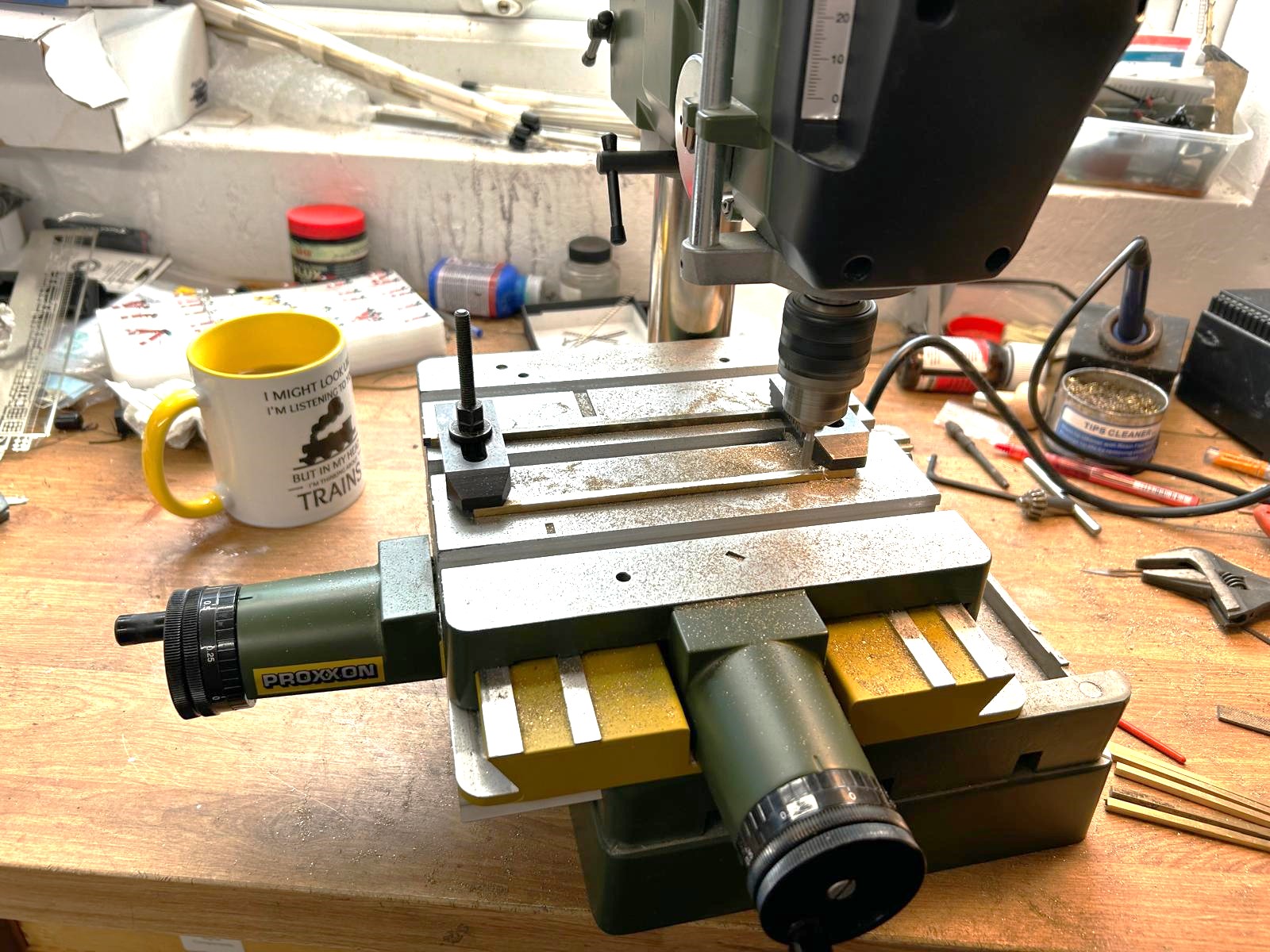
I propped one end of the post to form the correct taper with the mill travelling level. it was not without problems as the brass tended to flex (upwards oddly) where it was not supported. I ended up using the mill to take most of the weight off the metal and then went back to the files to finish the task off. It does reduce the effort, but it is still hardwork – and i have only done half of them so far!
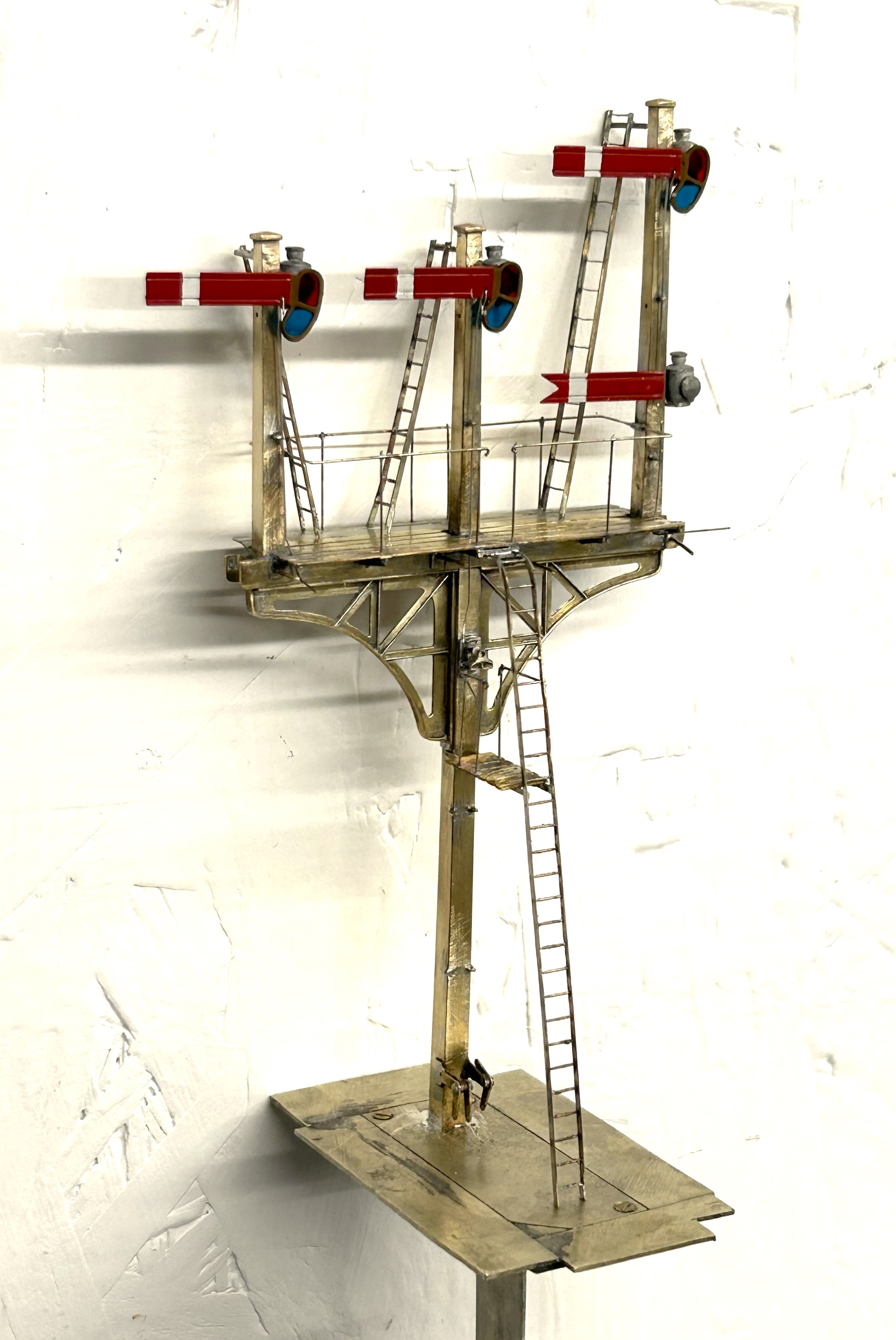
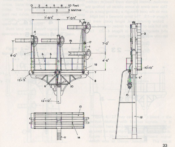
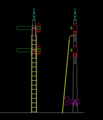
The first signal up is a LNWR three doll signal with three moving arms plus a fixed distant. Nearly as shown in this official drawing.
The basic posts and dolls are now in place; with various scarp etch temporary strutts to keep it square. Still a long way to go though!
So i wish you all a great Christmas and a Happy New Year.

Now That Didn’t Take Long…………..!
I have recently bought one of these – a minature bench saw by Proxxon – second hand from ebay for a moderate amount of money, along with a diamond disk with the intention of using it to cut copper clad fibre glass.
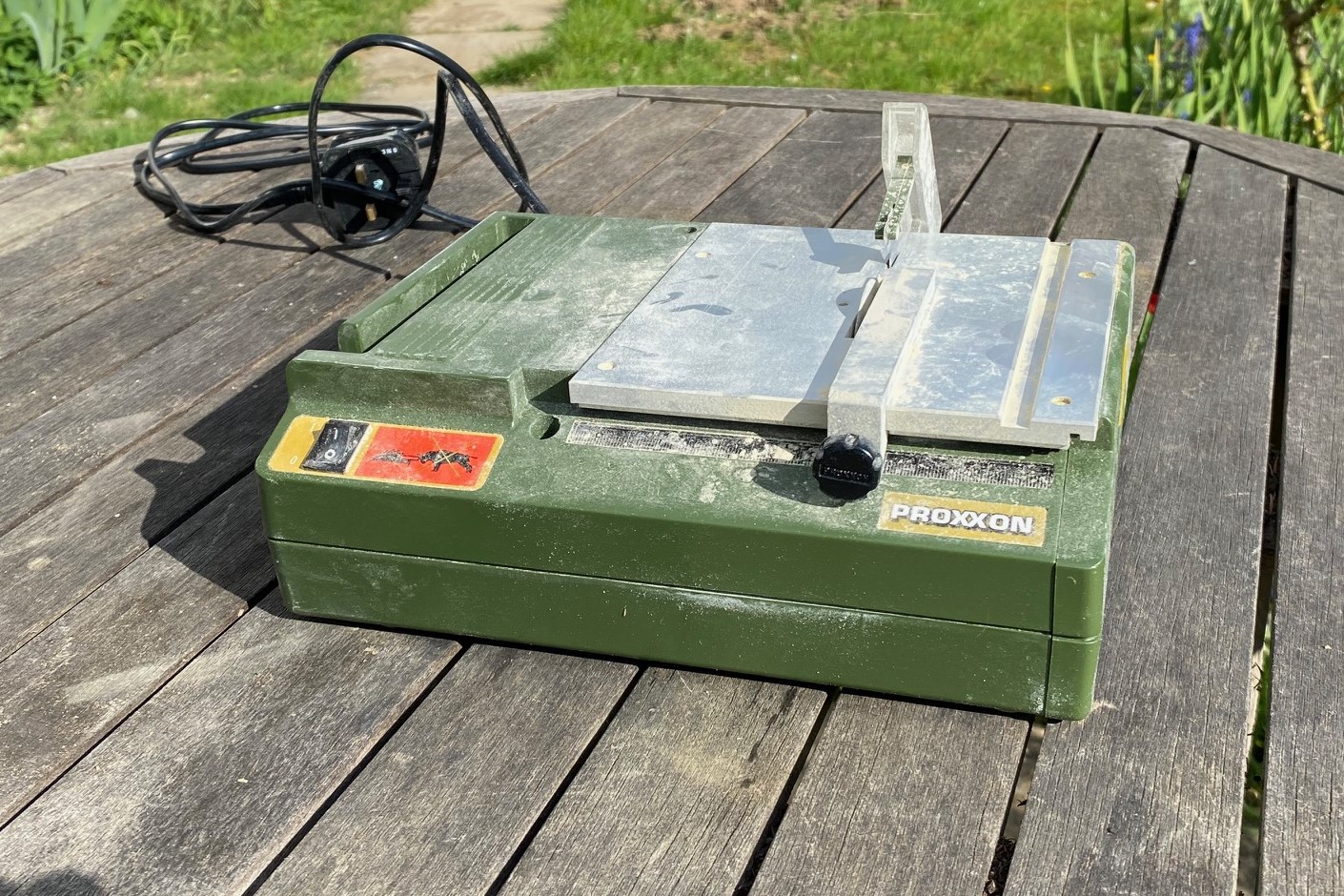
If you have attempted to cut copper clad sheet yourself you will know that it is a stunningly good way of blunting tools!
I wanted a better way of cutting copper clad sheet for frame spacers and, particularly, sleepering for trackwork. Having got it I obviously wanted to put into use…………..
So obviously I didn’t choose something simple and instead opted for a scissors crossing because I have never built one before. So here is it, a B7 turnout scissors crossing in P4 with a relatively wide line spacing as this is to be used in a fiddle yard between the up and down roads .
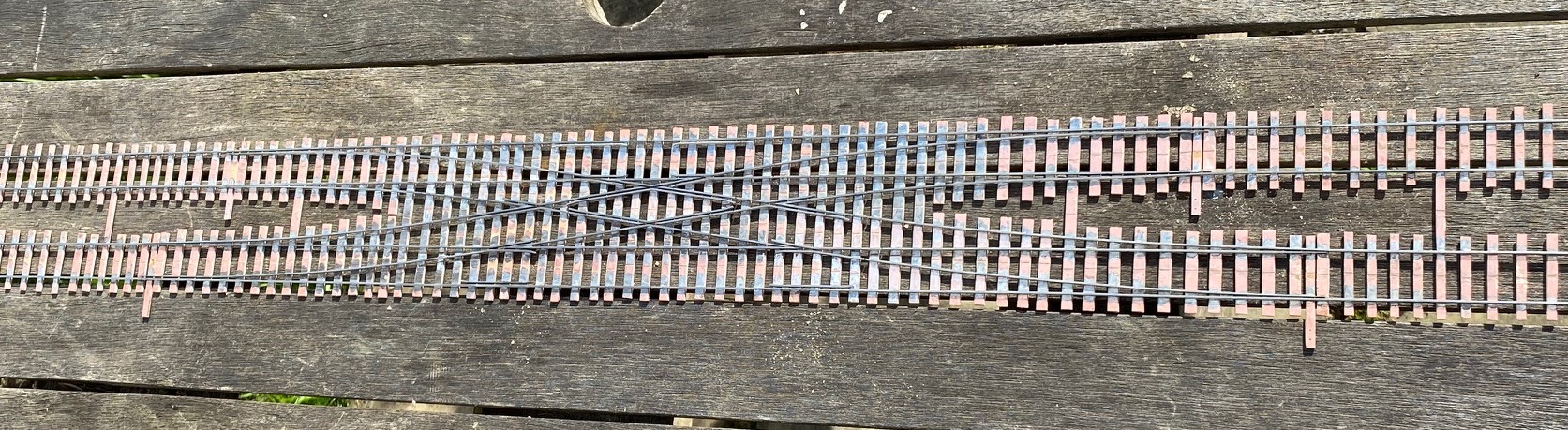
This represents over 24 hrs of work even though the time to make the sleeper bases was quite moderate.
My conclusion on the bench saw is that it is a much better way of cutting through copper clad sheet. The diamond blade slices through it easily. What is less good is that for fairly narrow strips (such as sleepers) it is difficult to get a consistant width along the strip even using a fence. Not a problem for fiddle yard track, but if it is to be used out on the front, it will need to be better.
I have also spent some time thinking through how i can wire this as it is quite challenging for the crossings for the central section. After much pondering, i have decided it is not challenging at all as i will simply cheat and use frog juicers !

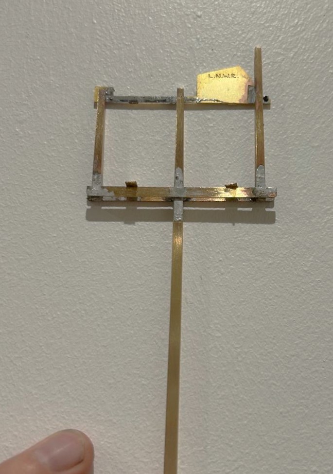
Still Swapsie – A Signal for Nampara for Hendrawna Part 2
Having assembled the basic post and ensured that it was working, the bolts can be filed away and we get to the following stage.
The spectacle plate plate is rather unusual in that it only has one lens which isn’t available via any manufacturer and the arm is notably shorter than I am used to so I had to etch these to suit. Although I could not find a lamp that matched what was on the prototype, I was able to modify a MacKenzie & Holland lamp from MSE to suit. Thereafter, the remaining assembly of the signal was fairly unremarkable.
And then once it had been painted, including the unusual red highlighting on the finial that I rather like:
And of course we must have the obligatory video to show that it really does work!
And for those of you that might want it, this is the drawing of the signal, which has two arms, at Didcot.
Swapsie – A Signal for Nampara for Hendrawna (Part 1)
Swapsie – the childish act of swapping things according to Wiktionary.
Do you remember at school swapping a Top Trumps set for a the latest Hot Wheels car or similar? I do! I remember getting roundly b*llocked by my mum for not recognising the value of things I was giving away and (metaphorically I am pleased to say) swapping gold bars for glass beads almost like the Incas and Cortez.
In the world of toy trains, the same happens and is very useful where someone can offer something that you don’t have (or find difficult to make) in return for something you do have. This is one such example. Sitting next to Duncan Redford at an EM Gauge Society/Scalefour Society skills day a few years back demonstrating signal construction a barter was arrived at whereby I would build Duncan a signal in return for him doing some 3D design and printing. I think it is fair to say that neither of us have rushed with our respective shares of the bargain but with the next ExpoEM only a week away, I have shifted into gear to finish the started signal that was my part of the deal.
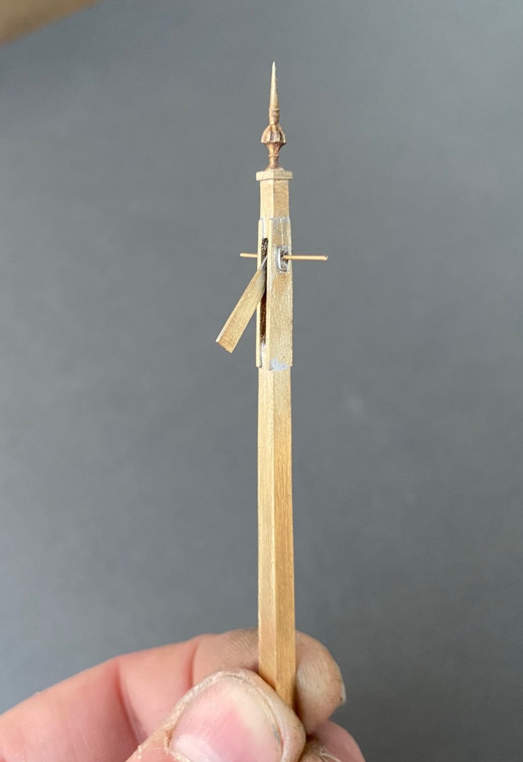
Duncan is building a GWR broad gauge era layout and wanted a close replica of a signal that the GWR Society has recreated at Didcot, but adjusted to have only a single arm. So after coming out in cold sweats about the idea of modelling anything GWR (!!!) I took a look at it. Like many signals, there are differences and similarities with other signals but after a bit of study it became clear that it was sufficiently different that a site visit to Didcot to be required.
Having measured it up including, when no one was looking, a climb to the arm/lamp to measure it, I came home to draw it. I was shocked to find that it was tiny; 3mm/1foot at best and I had a panic attack -had I mucked it up and mis-measured it. Obviously, being a professional surveyor I could not possibly have done that, could I? After a few months, the fear that I had niggled on me and so came about site visit number 2 and a further climb up the signal ladder. Nope, it really is tiny – both the post and the arm are notably smaller than I am used to.

There are several unusual aspects to the signal; the one glass spectacle plate, the tapered arm and the very pronounced stiffening around the slot in the post were all going to be key to capturing the character of the signal. So out came the computer and a small fret was added to an etching order for the arms/spectacle plates. I then formed the basic post from 4mm square section brass which I filed to a taper with a 2.5mm cross section at the top.
Despite having built a few slotted signals already, they are still pretty difficult to get to work well. The difficulty that I have had is to get a soldered joint onto the arm spindle when it is encased in the brass post around it that acts as a heat sink. On a number of occassions the joint has broken and the arm no longer operate. I was determined this was not going to happen this time and have adotped a different approach, by assembling the arm first and then mounting it within the post whilst this was being assembled.
I had filed some 4mm square section into a taper to form the full length of the post. Even though I was about to cut a section of this out, it is necessary to form the full length of the taper so that it is consistent across its full length. Once I was happy with this, i filed two pairs of slots in the outside of the post on oppposing faces. The depth of these was such that the tongue between them was the correct size for the slot in the post. I chose to mount the finial at this stage, with some 296o solder and a lot of heat (from a minature blow torch). This is what it then looked like:
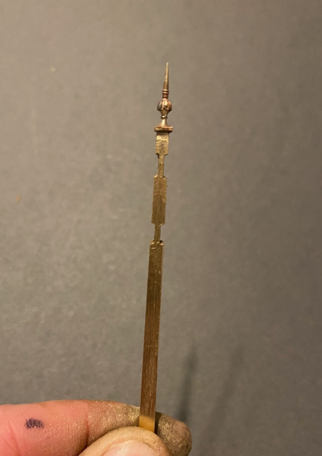
Next, I cut away the block of post that sits between the two filed sections to create a hole in my post. As there is around 2 hours of work to get the post to this point, it is a bit nerve racking chopping it like this! I then cut a pair of 1*4mm brass plate lengths to sit on the tongues and drilled both to receive a 14BA bolt. This was threaded through the first of the plates and adjusted until this a continuation of the taper of the post – this entails some filing of the metal to make the outside face match the post and plate match. It was then soldered in place, again using the 296o solder and a blow torch, to look like this:

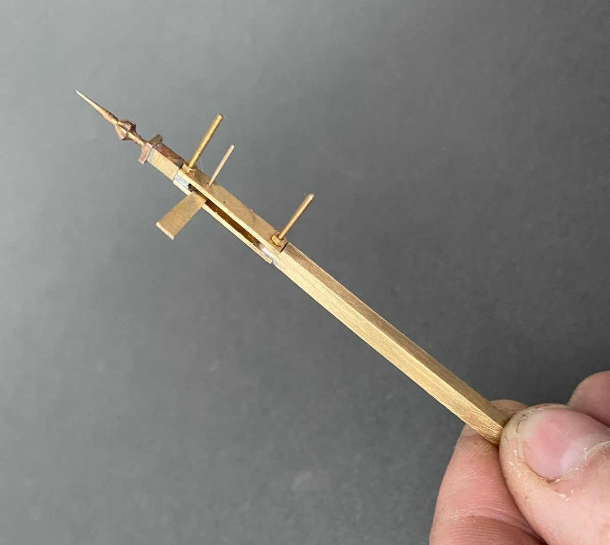
The photograph above shows that these plates were wider than the post, in practice the prototype acheived this by planting timbers across these sections but it is easier to do this by way of using the sider plate material.
Temporarily mounting the second plate enables the hole for the arm spindle to be formed through both parts of the arm. The arm was now attached to the spindle with more use of the 296o solder and the use of a couple of minature washers either side of the arm so that I could be confident that the joint would hold.
Releasing the second plate now allows the arm/spindle assembly to be inserted and any adjustments made to ensure that it can move freely in the slot by securing the second plate in place with a 14 BA nut. The nuts and bolts are scarificed in the build by leaving them in place for the next step because once I was happy that it was correct I soldered the second plate in place including the nuts and bolts. This time I used 145o solder which meant that it would not disturb the first plate as I was doing this and this is what it then looks like – a slotted post with an arm within that is firmly attached to its spindle!
More to follow; including the second piece of bartering that I know someone is looking out for progress on!

Delayed Delivery – Part 2
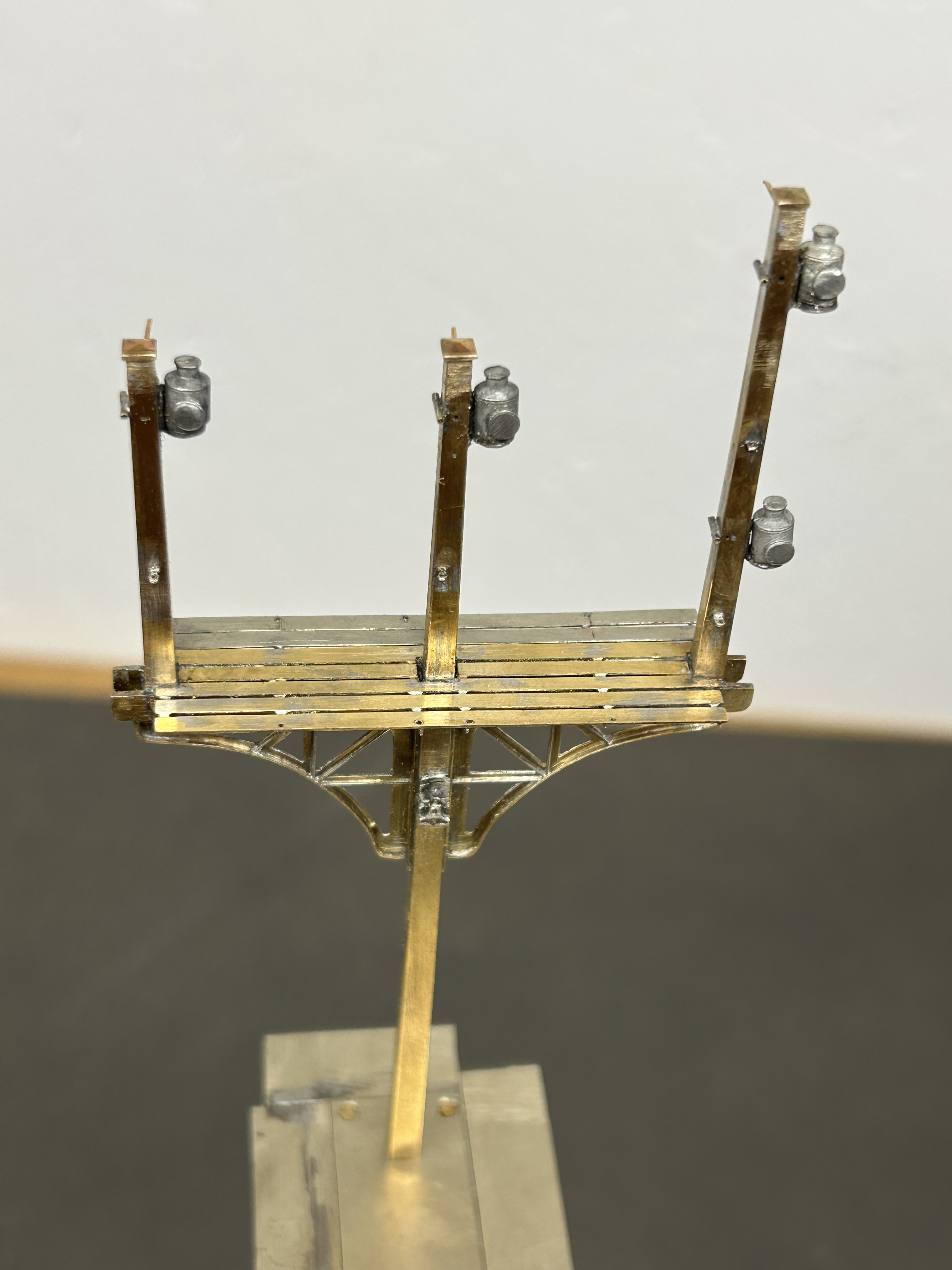
Once the basic structure of the gantry is in place, the real task of making the signals signally commences. First up were the smoke deflectors and the brackets for the balance weights. Also fitted are the main portions of the fan route indicator, but that will be explained further once I get it going!
For the arm bearing point and lamps I am using some 3D prints produced by Steve Hewitt and available from Shapeways. They can be found here https://www.shapeways.com/product/JJRSB … arketplace. They are fairly expensive but they are neat and save a lot of manufacture. There is, however, a but – they are very delicate and I am very fearful of thier long term durability. I am highly likely to draw some of my own up and get them cast in lost wax. It will make them even more expensive but I have about a 50% casualty rate at the moment, so maybe in the long term it will be cheaper!
The arms are Masokits, these are definitely the best available arms for LMS/LNER/BR semaphores. This is especially true of the minature shunt arms as the MSE ones are simply too delicate to bother with (imagine how do I know that………….!). So this is where we are now at with the arms mounted temporarly on the bearings.
There are five movements in the down direction (three of which operate via the route indicator) and then a pair in the up direction – hence the back to front arms.
The plates at the top of the dolls are mounting points for ladders. It transpires they are wrong and have already gone!
So the intensity level has dialled up a notch with these portions (especially breaking the bearing/lamp fittings) but it really gets interesting when you try and make these things work.
I don’t know myself yet (although I know for the couple of arms I have finished, so I have an inkling), but i think it might be fun to have a little sweepstake on how many moving parts there will be in the finished gantry. Five arms, three fan route indicators and each is operated by way of angle cranks. Each arm, crank and intermediate wire counts as a moving part, as do the servos………………..guesses please?

Delayed Delivery – part 1
After a long pause, caused by that irratating thing called life getting in the way, I am looking to deliver on some long made modelling promises over the holiday season.
The major task is a rather full on gantry signal with no less than eight movements on it (which is an improvement, when initially designed it had nine!), including a rather natty fan route indicator. This is for a friend’s layout and is in return for some signal cabins that he built no less than 15 years ago – I told you the promises were long made! Mind you, he hasn’t got the layout fully running yet, so I am still ahead of him!
The gantry spans only two lines so it can be formed with channel section. There are good drawings and pictures in LMS Journal no 5 of this. I have made mine from milled brass section and then the landing was a custom etch I designed as it takes a surprisingly large amount of material and effort to construct this from scratch. These etches included the doll base plates although the dolls have a thickened tube at the lower level which of course I forgot and had to undo later work to put on!!
The signal is to be located on an embankment which meant that I could not simply put flat base plates on the foot of the gantry columns. Instead I have constructed a housing that matches the slope of the embankment and then the baseplates are partially sloped to match this with square sections representing the foundations of the prototype columns. Below these baseplates I have then formed housings to take the servos which will eventually operate the arm actions.
So far, this is pretty easy modelling (although I lost a number of drill bits opening up the stanchion positions on the landing – grrrrrr!). The tough bit comes next……………
There are potentially two viewers of this thread who might be thinking that I have long outstanding modelling promises to them too……………I am also working on one of these too!!

Fuel for Thought
Obviously, where there is water in a locomotive yard, there really ought to be coal too.
The Highland, like many other railway companies of the time (certainly the Scottish ones), sought to stockpile coal. This was presumably insurance against coal strikes and allowed them to purchase coal at times when the price was favourable. Thus, quite substantial coal stacks where very much a feature of shed areas in the pre-grouping era. Typically, these were arranged in engineered stacks, with the sides formed in “dry-coal walling” and then loose coal behind. I can’t recall ever seeing this modelled, so I though I would change that!
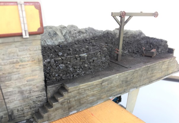
The actual structure of the loading bank was formed in plasticard and Wills random stone sheets, but with the mortar courses softened as I described for the water towers. The shape of the coal stack was formed with a piece of house insulation left over from a DIY job and then real coal used to form the effect of…..err……real coal. Actually, real coal does not look quite like real coal without a bit of effort. It does shatter into angular but irregular lumps like real coal (especially if lignite coal is used) but its glossiness does not scale down. However, a vigorous brush with generous amounts of soot black weathering powder takes the gloss back and the whole becomes quite convincing. You do feel as if you are going to get pretty filthy if you go up onto the bank – and until the whole is fixed with matt varnish, you would!
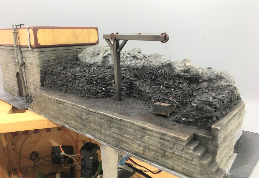
Individual coal chunks were glued in place to form the wall structure. To get the effect, it is not enough to simply scatter the coal onto a bed of glue each chunk has to be laid individually with care taken to lock it into the course below – just like a real dry stone wall. Thus, the vertical walls of this took about a day to complete, scattered over about 8 stints because it is necessary to let the glue dry after every couple of courses to stop the layers collapsing. It is then possible to scatter the loose material behind the walls onto a layer of glue – the above picture shows the contrast in effects between the two methods.
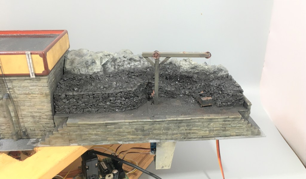
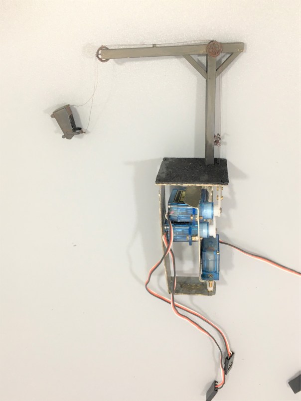
But it is hard work shovelling coal into tenders, especially as the locos got larger and their tenders higher. As befitting such an important place as Glenmutchkin, it has all the modern amenities for coaling engines, a hand crane and a large bucket! In this case, I have fitted servos to this so that it operates – partly as a bit of fun and also to slow things down in the yard to a more realistic pace without it getting too boring for the viewer.
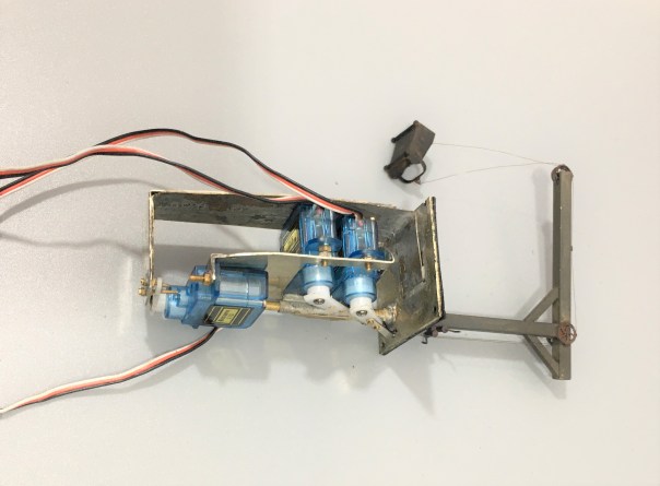
The crane operation was achieved by way of three servos – one to rotate it and then one each for the front and rear of the coal bucket. These are all mounted onto a cradle that is rotated by the former – thus as the crane rotates so too do all the servos and there is a quadrant shaped slot in the base to the rear of the post (just visible in the picture above) that allows the cables to rotate too without snagging.
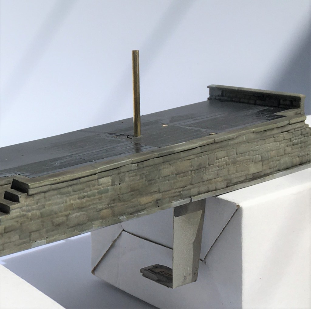
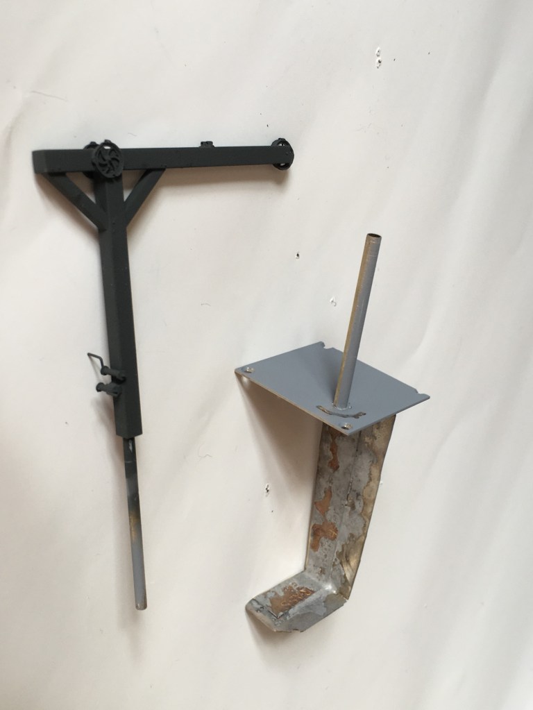
The cradle is mounted to a solid rod that is in turn secured to the actual crane. This then slides into the rod that can be seen projecting from the base in the picture above. This means that there is limited strain on the crane or the mount as I had feared it might otherwise snap with any heavy-handedness on my part (something I am prone to!). The rest of the crane was made with brass hollow section and pulley wheels from Bill Bedford. A series of guides were made of small section tube on the pulley wheels, at the winding drum and across the jib to retain the operating cables.
The bucket was fashioned from metal sheet and is filled with low melt solder to give it as much weight as possible. It is secured to the servo arms with invisible thread – which is a nylon seamstresses material used for making invisible stitches. It comes in both clear (which really is invisible) and black, I used the latter. It is much better than cotton thread as that has a furry finish that looks terrible after a time or if it is painted. It is, however, very fine and rather wriggly to knot, so using it involves a certain amount of cussing!
And this is what it looks like in operation…………
A little of the bouncing about of the bucket is caused by it sitting on my servo test rig, so the act of changing the switches imparts a little vibration. Hopefully, when mounted on the layout this will be less obvious.
I do still need to do the final detailing on this; tools, a bit of discarded debris and a couple of fellas from Modelu standing around doing nothing (because static people in animated poses look silly on a model layout!).
Only the printable words for this Wednesday!
Hmmmm……..
A signal imitating a Fresian cow was not the effect I was after…………..
Halfords etch primer is obviously not that etchy!…………….. So someone will be waiting a tad longer for their signal than I thought…………
