Blog Archives

Scrap Tank Test Build – Part 4; Beginning the Chassis
Putting aside the body for a while, to take a look at the chassis because it is necessary to mount the two together and it is not possible to close up some of the element of the body until this is sorted out.
As with the body, I am trying to take a moderately fresh approach to the chassis to make this a little easier to build than certainly most of the kits I am used to. In this regard, most of the kits for the Highland are quite traditional in their design and I readily admit that all but two of my ideas has been either all out pinched from other designers or at least significantly inspired by them. All I am trying to do is use more of these neat ideas in a single kit to make the life of the builder easier. I am, however, finding that it makes my life more difficult, as there are a lot more moving parts to most components, so more places for the tolerances to be catered for; so as John Price has already said, the list of little tweeks and amendments to make is growing! At least, no one can say this particular kit designer has not built their own model.
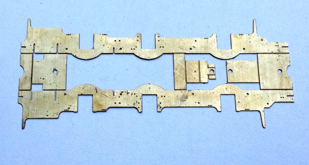
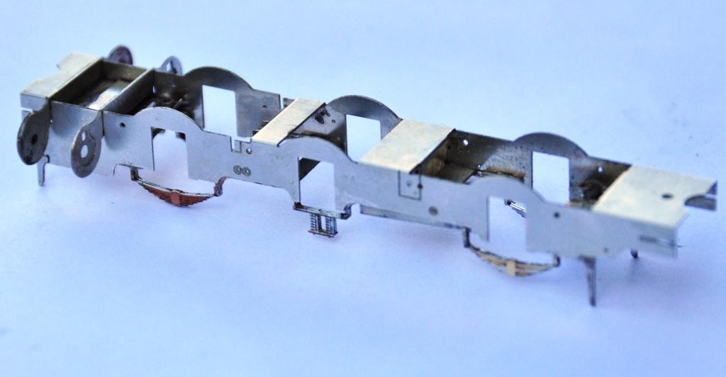
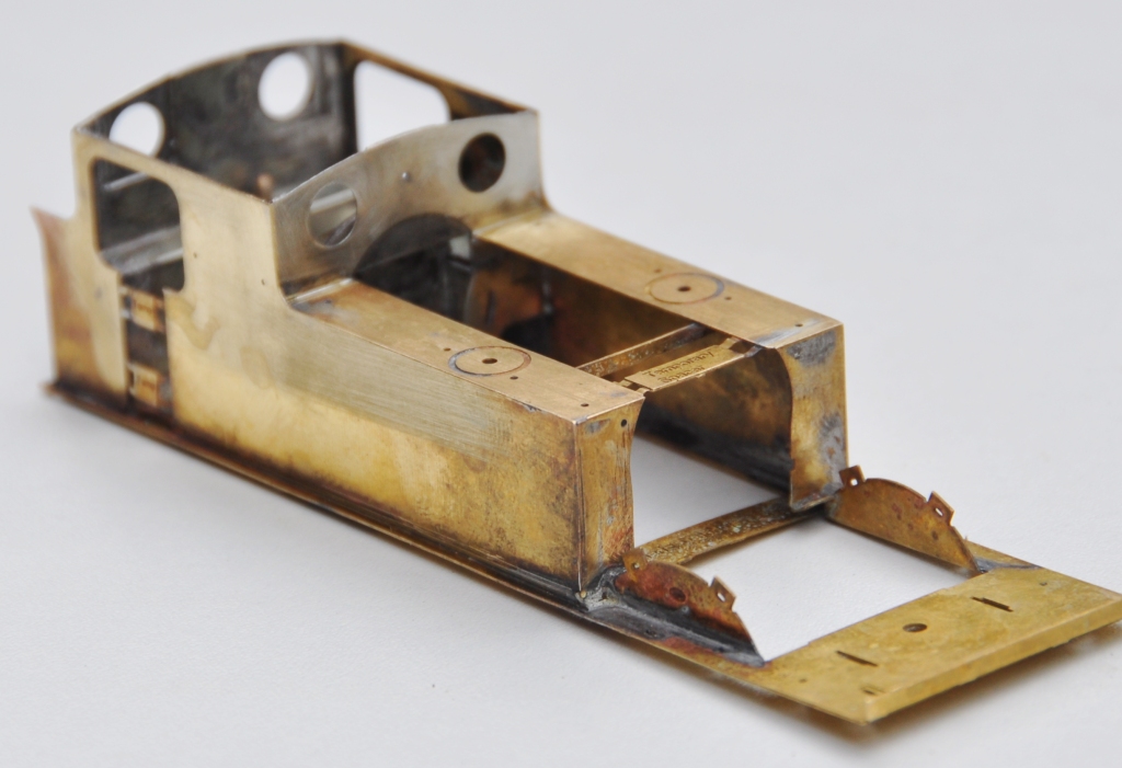
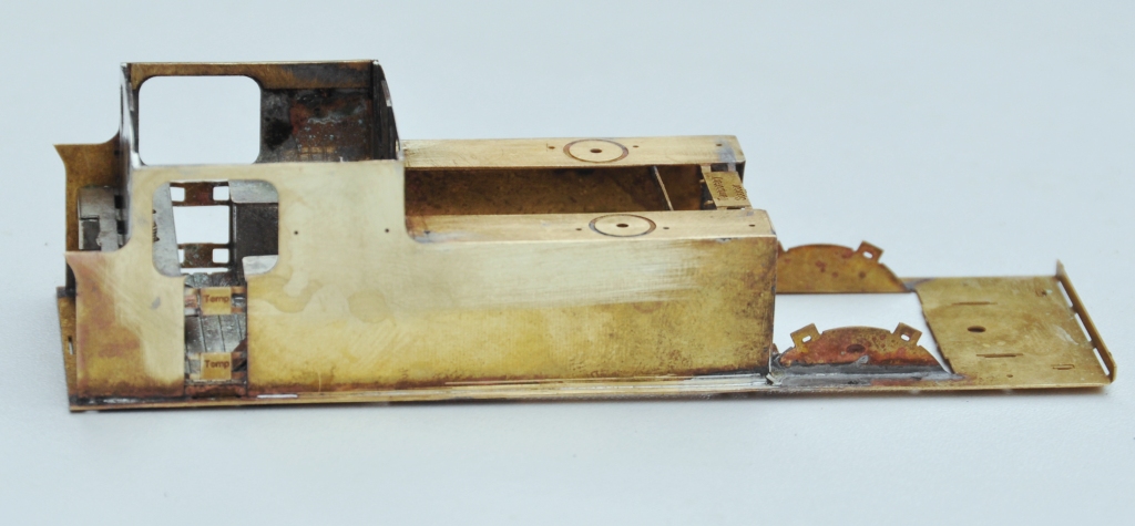
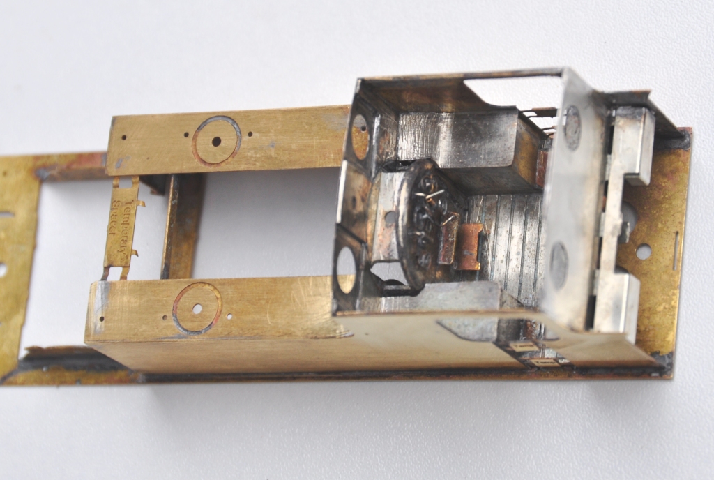
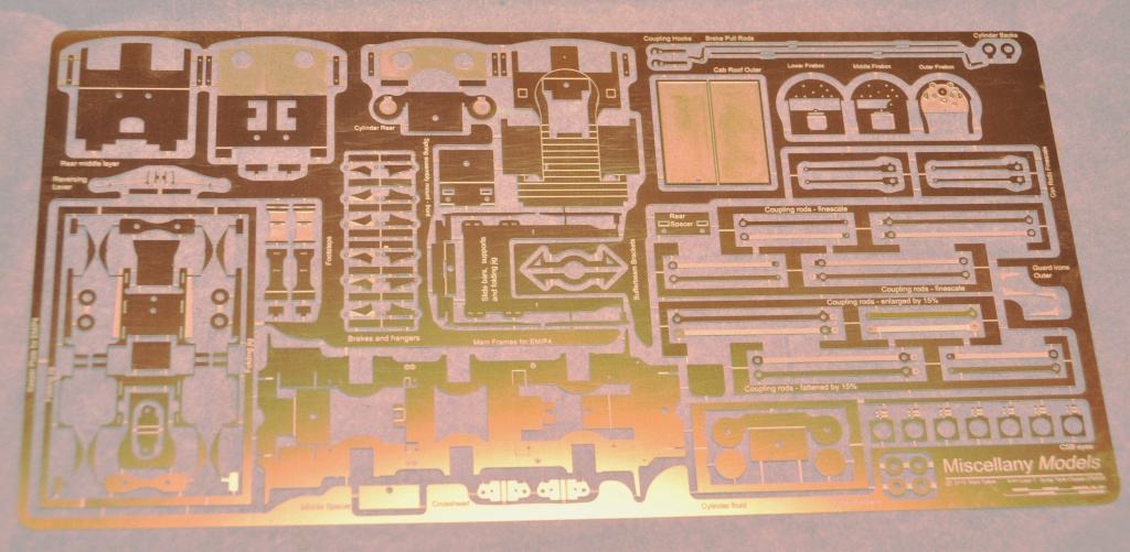
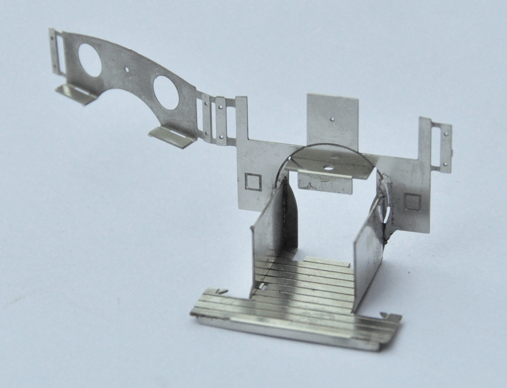
Anyway, this is what the chassis looks like in the flat; note that it is a fold up design – this is inspired by the Mousa Models chassis, so a pinched idea!
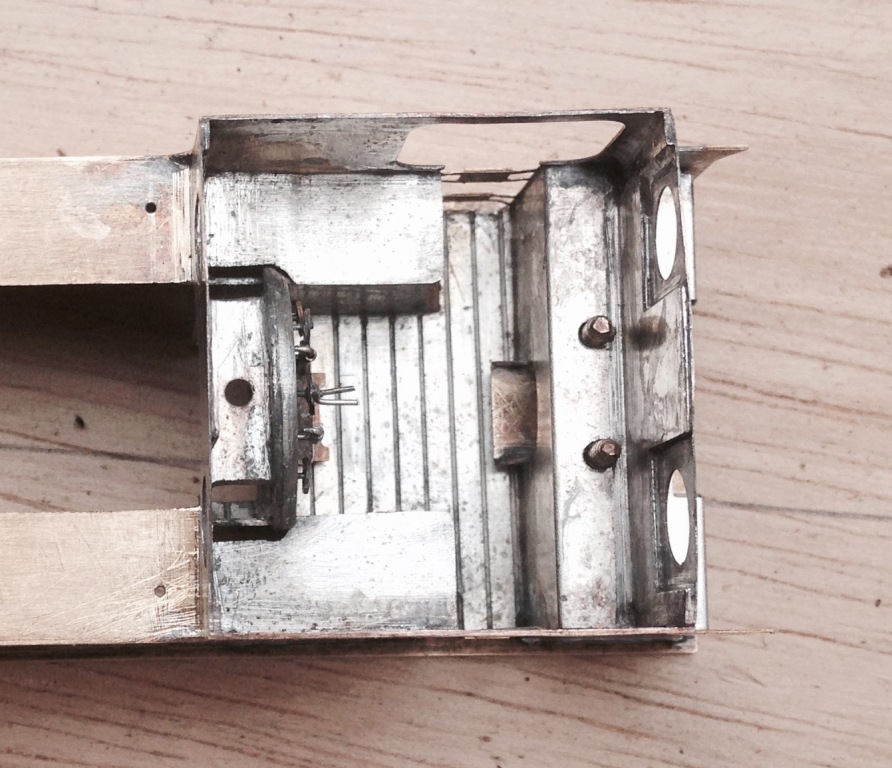
And this is what it looks like with the basic folds made up. What it achieves is really neat, as it is instantly sufficiently stiff to work as a chassis; by the time a couple of further cross braces have been installed the basic chassis is more than robust enough for its life.
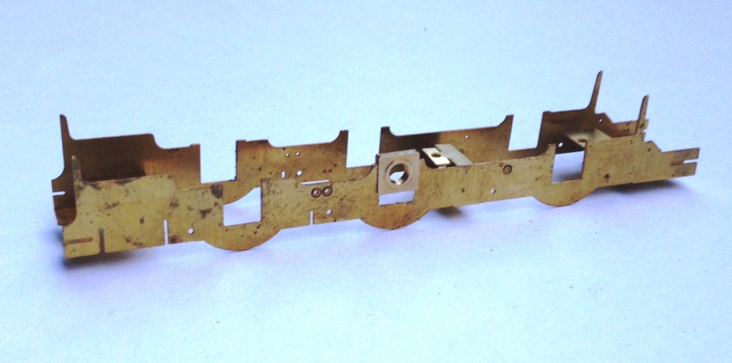
My design uses the same slide in hornblocks as utilised by Comet and Brassmasters for their chassis. After a tiny bit of practise, it is possible to size the hole for the hornguides such that these are just too small when etched. This means that with a few strokes of a light cut file on each side, the hornblock becomes a tight sliding fit. Once all of the hornblocks are in, it is then possible to measure the distance between each on both sides of the chassis and also on the corresponding coupling rod. This is done with digital callipers and by the expediency of measuring the distance at its maximum with the callipers facing outwards and then repeating with them facing inwards the average being the actual distance between the centres. I reckon to be able to measure down to 2 or 3 hundredths of a mm, which is rather better than I can build to! Where there are inconsistences, this is dealt with by a few more strokes of the file on the side which needs to be adjusted to change the centre. This needs to be done anyway to turn the tight sliding fit to a snug but smooth fit for the hornblocks to work properly soif the centre does not need to be changed, the file strokes are undertaken equally on both sides of the hornguides.
This does need to be done after the coupling rods have been formed, of which we will see in the next posting. However, the chassis is also designed with a keeper plate to accommodate all of the cosmetic springing to the model and the ashpan sides. This is secured with a series of 12BA screws to enable it to be removed to allow the wheels/axles to be dropped out. A great boon as the model is built and painted.
To make the assembly of this element easier (in fact in this case a lot easier!) I have created a jig that holds the two layers of the laminate in exactly the right position. The jig is chunky enough to avoid distortion as it is folded up and it locates the parts perfectly. In this particular case, the soldering needs to be done with care as there are folds to make after the jig is cut away and it is important not to fill this with solder before hand.
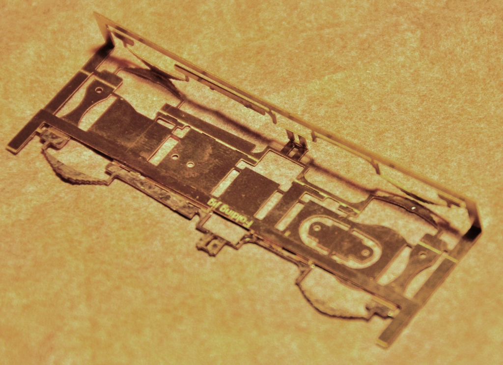
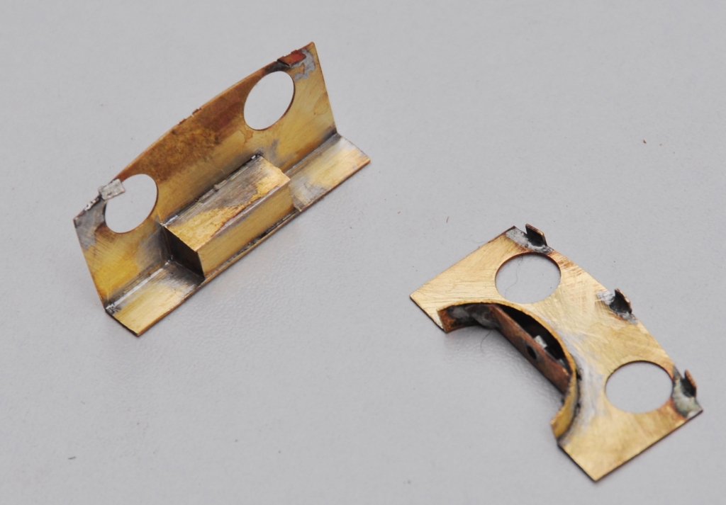
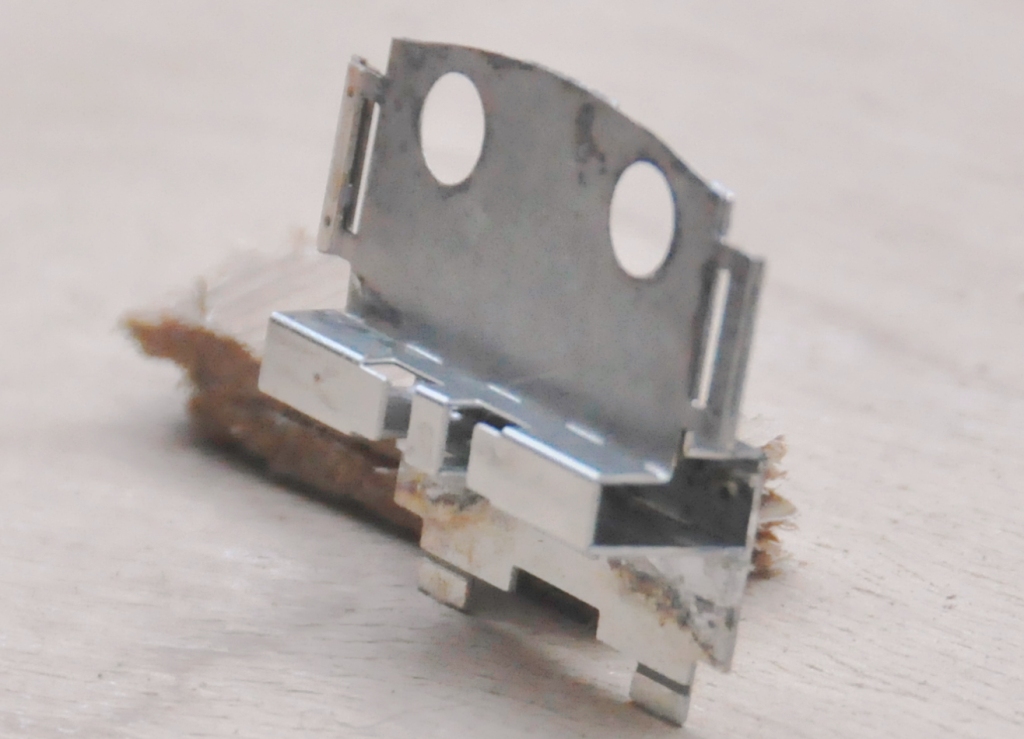
And this is what the keeper plate looks like – it is pretty delicate until it is mounted but fine thereafter.
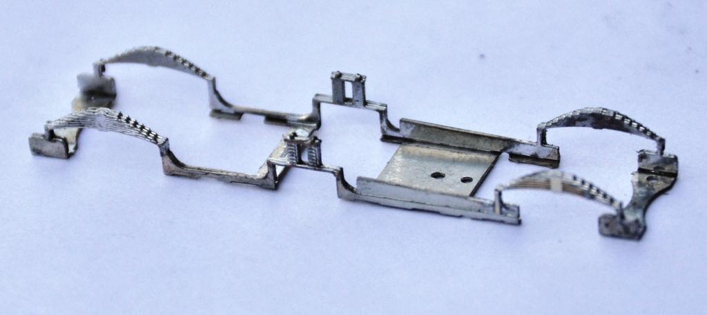
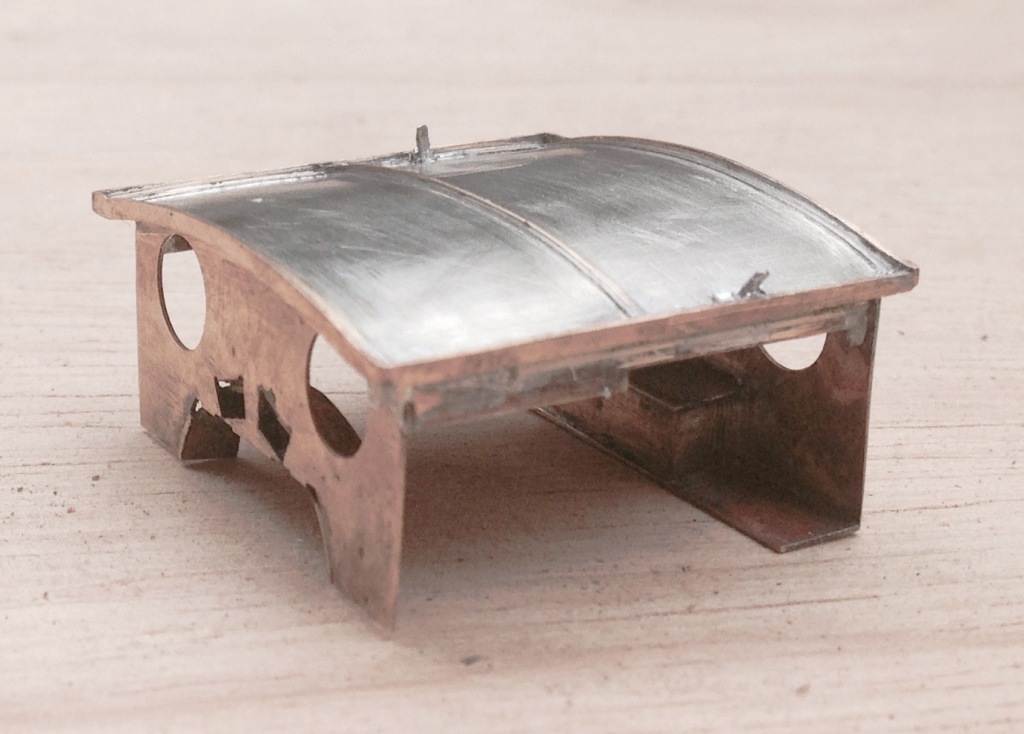
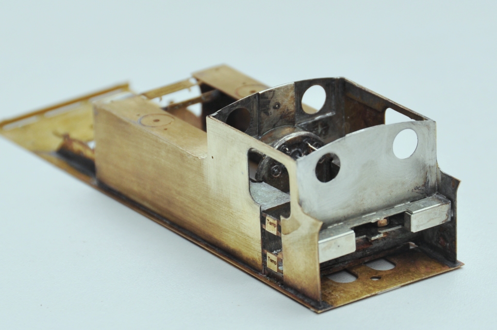
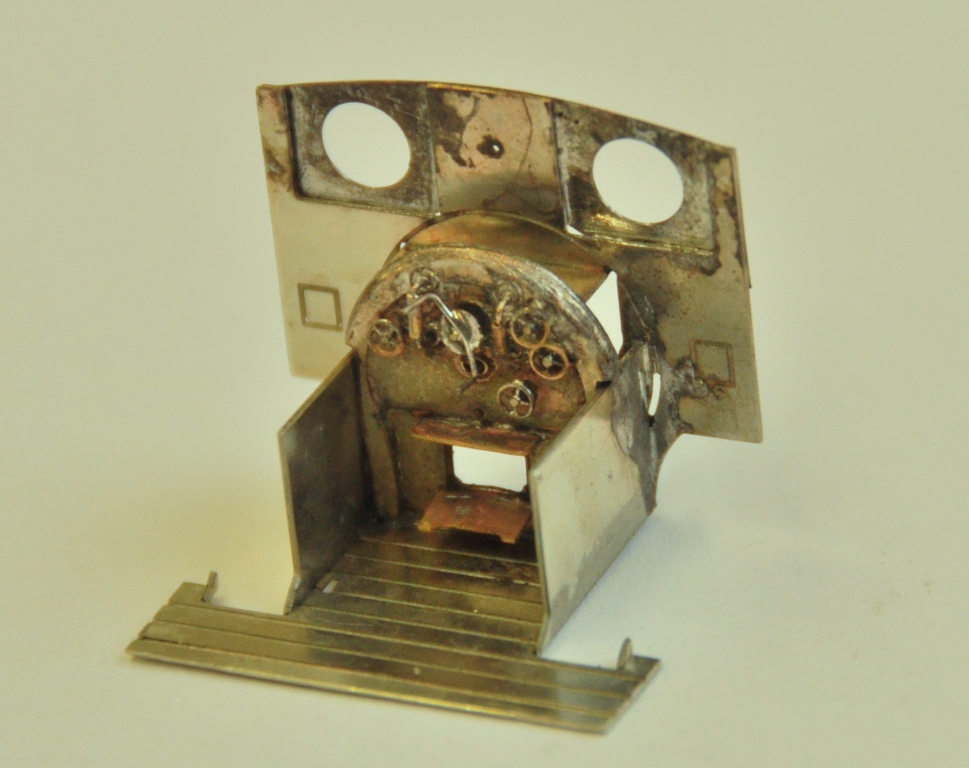
And the two components assembled look like this. The beginnings of the cylinders are also visible, this is a slide in module that can be removed for assembly and painting (although the scrap tanks were painted fairly simply, so this is not really relevant on this model).
Scrap Tank Test Build – Part 3; Cab Inner & Roof
I have designed the cab roof and much of the cab interior to be a separate assembly, that can be secured by a series of screws. As can be seen below, there are two screws at the rear that locate into a tool box that sits on where the bunker projects into the rear of the cab. As the screws are somewhat lost in the bunker, I have come up with a little dodge where these are retained by an initial nut that traps them in place but still allows them to twist and thus engage in the cab roof assembly. The other screw comes through the top of the boiler, just inside the backhead.
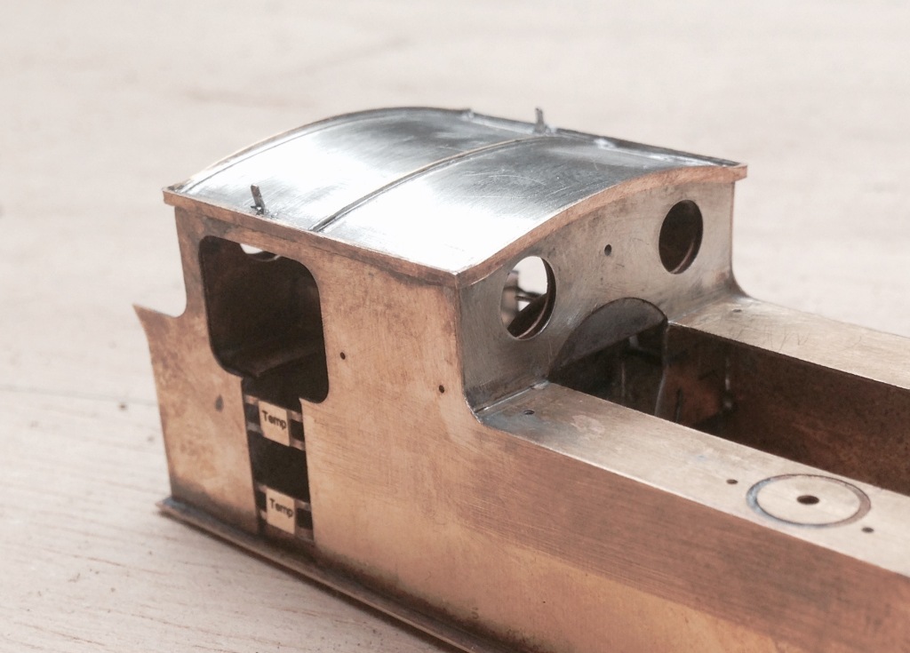
The roof is connected to these fixing points with some inner liners to the cabs which can be seen here; the nuts for the rear piece are hidden in the toolbox and to the front within the false top to the boiler. You can just rebate in the rear spectacle plate that will take the glazing material.
The actual cab roof has a double skin, to aid its strength, include the lamp irons and also to assist with locating it on the cab. The outer skin includes the ribs that appear on the real roof, including a grove to allow brass wire to be used to form the seam to this. To the perimeter of this, there is a valance.
And this is what it looks like on. I find that I just can’t make roofs sufficiently well to sit perfectly on the body and nothing shouts “its a model” more than gaps where there shouldn’t be any – be this under buildings, roofs or between parts that have to be joined to structurally stand up! This is my solution, which I have used on other builds that I have done but it is so much easier when it is designed in.

Early Pattern Lookouts for Dia 38 HR Goods Brake
I have been doing more with the Scrap Tank, but I haven’t managed to take any pictures due to needing flippers outside yesterday. So instead, lets see something else that was on the test etch that I have recently had returned.
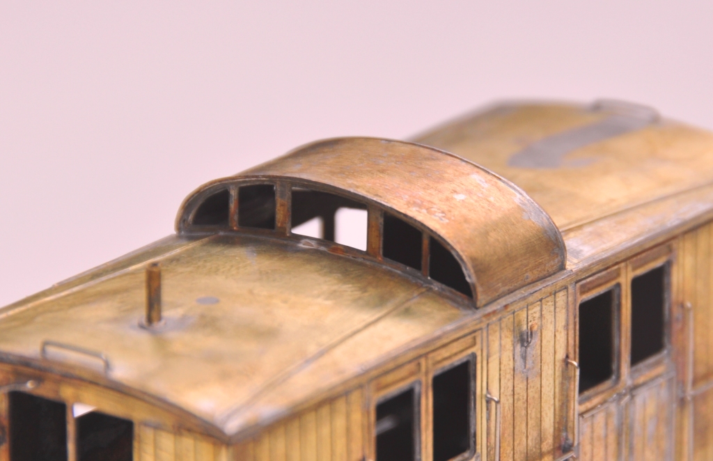
This is the early style lookout for the dia 12 Highland Goods Brake. As originally built these lookouts formed by a single slot to the centre of the roof and were fully glazed to the front and back. In use guards complained that they caught their heads on the lip of the roof as they climbed in. To overcome this, many of the vans were rebuilt to include ramped approaches to the centre of the lookout were incorporated, to become what was arguably the signature feature of the Highland’s rolling stock.
Microrail produced a kit for this van 30+ years ago and this included the latter style of lookout. I had a pair of these kits and ended up acquiring a third one and I felt I really could not have another one just like the first two! So I had an inspiration and thought it would be fun to make the early pattern lookout. The old man’s book came out and a scan of the drawing loaded up into the CAD machine. From here it was a relatively simple exercise to draw up the difficult bits, the glazed screens, and the more simple roof.
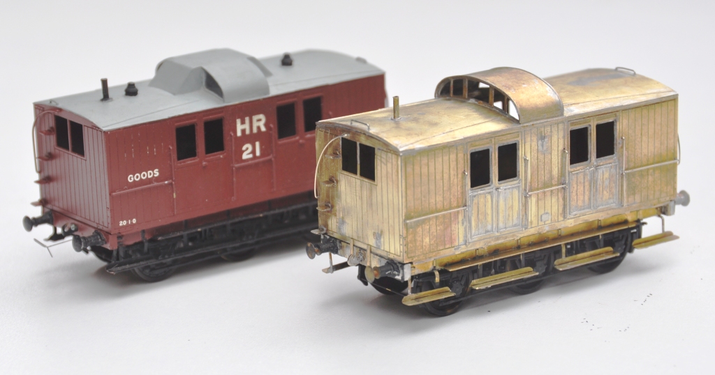
The components went together easily and do give a very different feel to the Microrail kit as intended. I also made a number of other adjustments, to the footboards and also the panelling, to make the model both different and authentic. The latter, the beaded panelling, is a right pain in the whatsit and took much longer than any other element of the assembly – so don’t to it unless really want to! And this is what it looks like next to the kit as originally intended, with the later style lookout.
I will be making these available via the Miscellany Models site shortly, when I have done enough of the other elements I am working on to do a production run. In the meantime, I do have a pair of very slight seconds (there is a tiny bit of over etching – almost impossible to see, the pictures of my vehicle have the same problem). These are available for the price of the metal; say £2.50, plus postage (which won’t be much). Ordering is via here: http://miscellanymodels.com
And the real thing looks like this:
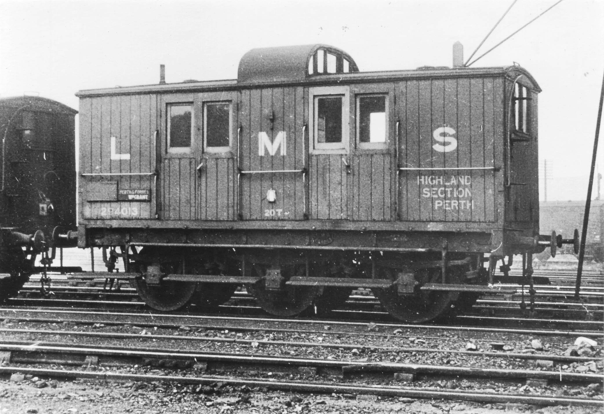
(C) Bill Steel
Scrap Tank Test Build – Part 2; Continuing with the Body
The next stages of the test build were to do the footplate/tank sides/can exterior.
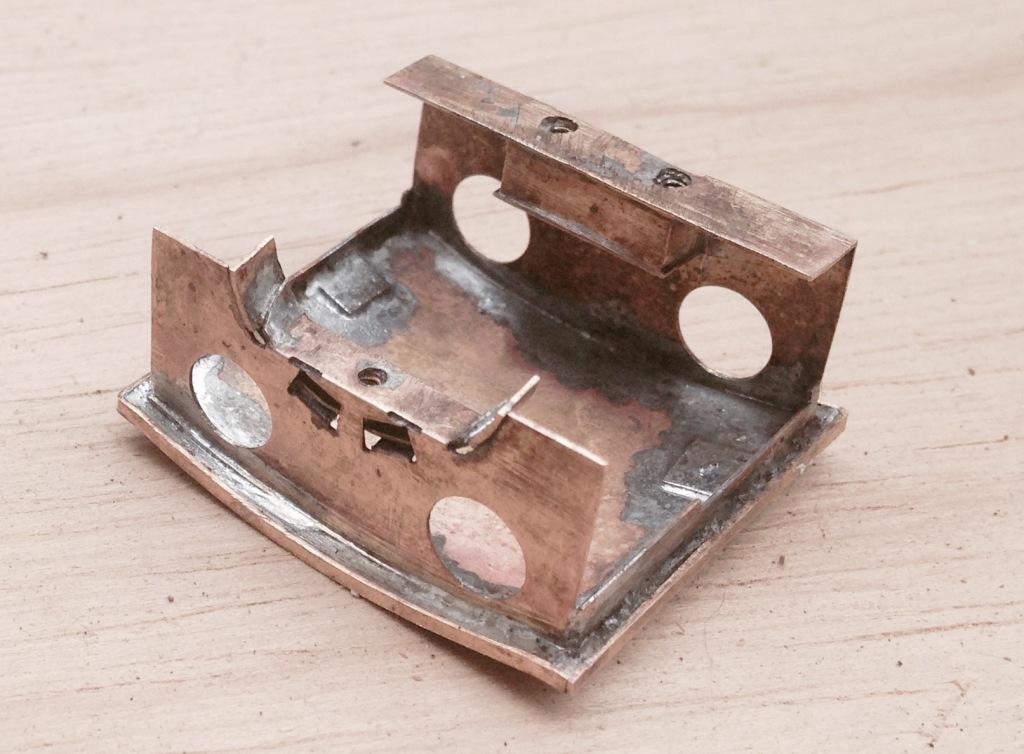
My initial design for the footplate is not particularly radical, but the test build has shown up that until the boiler is put in place (which comes some way into the build process) the front is somewhat delicate, irrespective of whether the footplate valences are fitted or not. Thus, in addition to the temporary stiffener that can be seen to the front of the footplate in the picture below, stiffeners will be provided to the front half of the footplates. The idea of these can be seen in the following view which shows the rear of the cab. By folding these over at 90o during the build, they give strength to the more delicate parts of components. Some will be incorporated into the finished article, others will simply be discarded when their job is done.
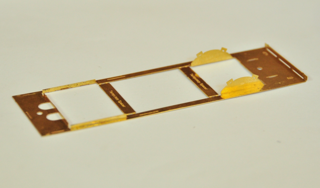
The two tanks, along with the sides to the cab/bunker, are conceived as a single piece (if you go back to my previous posting, you can see this in the flat in the etch). The two halves are separated by temporary spacers to both assist in locating them but also to give strength to the assembly prior to the fitting of the boiler which is where it will get its strength from. It was when I tackled this part, I reached the first disaster – the etchers had failed to half etch from behind so I was missing some fold lines. This was pretty frustrating as it entirely negated the intended efficiency of the design and even though I now have a corrected etch, I had to solder on by cutting the parts at the intended line of the half etch and soldering them together in the more traditional manner – exactly what my design was intended to avoid. As a result of this, there are no neat photos of the tanks being folded up and secured in place, we have to jump on a bit to see this.
The cab fronts that were constructed earlier were no slid into place and I was pleased to find that it all fitted very snugly and in exactly the correct location. I did find that I could put in a further pair of fold up tabs on the running plate that meant that it was essentially impossible to put this in the wrong location, so this is another little refinement that will make its way into the production batch.
The rear of the cab was a similar fold up unit to that to the front, which was pretty easy to build but did have one dimensional error at its base that needed cutting away – well that is the purpose of a test build! All of this, has been created from one piece in maybe three minutes!
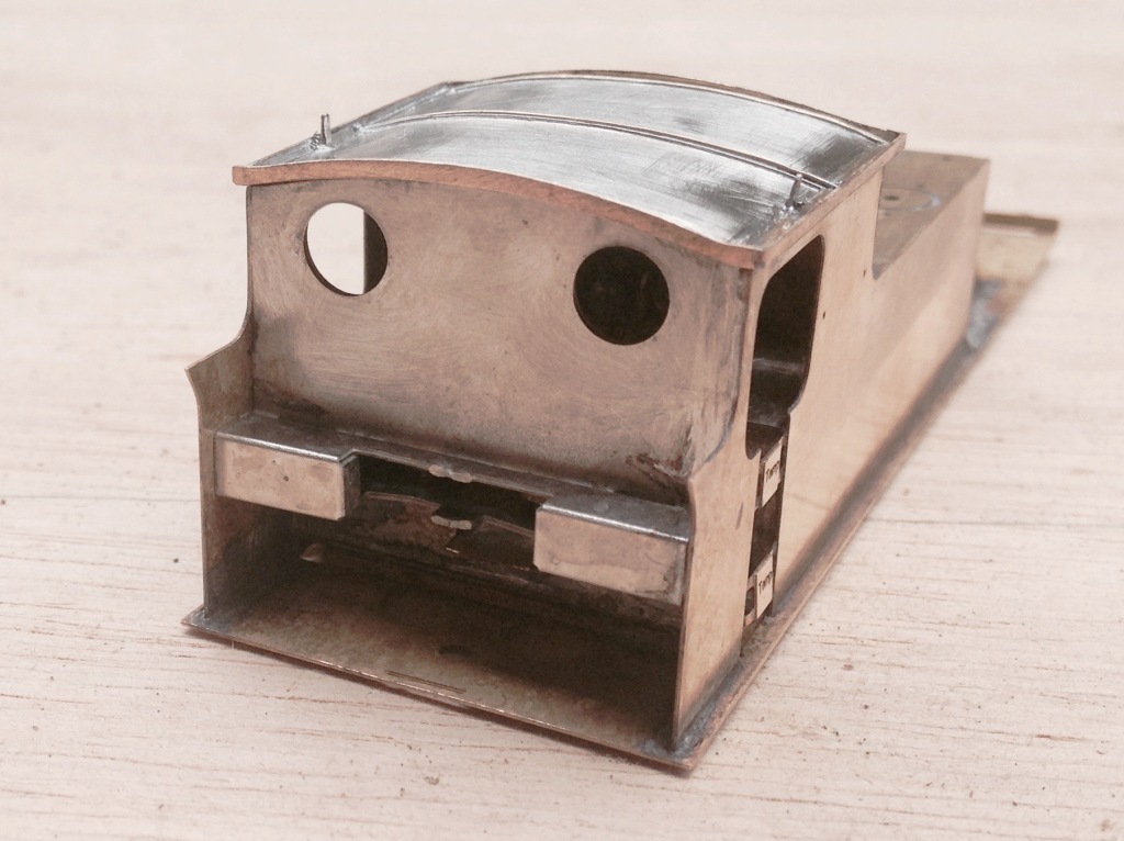
And this is what it looks like with the cab rear in place. If you look carefully, a couple of 12 BA screws are just visible in the cut out to the rear of the cab – the purpose of these will become apparent in a future posting but it is another one of my little ideas to make this easier to build/better when built.
And this is what the cab bow looks like from above, after the addition of the splasher tops and backs. One of the issues this illustrates is that this kit, as it stands, will only work for EM or P4 modellers. There is insufficient room to get the narrower gauge/wider wheel treads into the splashers.
Next up will be the cab roof………….
Scrap Tank Test Build – Part 1; Getting Started
I took the weekend off the other week and attended the Spring Railway Modeller’s Weekend at Missenden. It is great to spend two full days just modelling away from the distractions of life and amongst people who are all doing exactly the same. I find it a form of therapy and it is well worth going if you have been thinking about it (and even if you haven’t!).
I took with me the etches that I have had delivered by PPD for the Scrap Tank; with a view to doing a test build using them. The origins of this class are some of the earliest locomotives built for the line; the Raigmore class. In an attempt to increase the life of these new enlarged boilers were fitted to them. Unfortunately for the Highland Railway the boilers were too heavy for their frames and consequently these cracked. This left the Highland with a number of new boilers, wheels and many fittings but no locomotives! Ever the frugal, they recycled these parts into a series of three shunting locomotives which were designed by Peter Drummond and these inevitably quickly picked up the name of Scrap Tanks.
These were rather brutish looking locomotives for the time, characterised by surprisingly large wheels for a shunting locomotive – something compelled on the Highland due to them reusing these from the Raigmore class which were mainline passenger locomotives with 5′ 3″ wheels. For those of you who don’t know what these looked like, this is what we are aiming at:
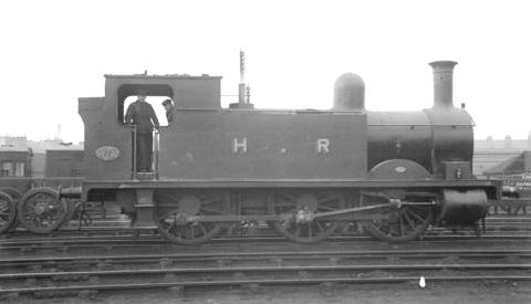
And this is what we are starting with:
Whilst this may (well has!) got me into some trouble, I have sought to design the kit to be easier to build than the average etched brass kit and certainly easier than the Falcon Brass kits that are the staple in 4mm for many of the Highland’s locomotives. I have sought to do this in a number of ways and the first area tackled, the cab front/interior, illustrates one of these; the use of fold up assemblies to assist not only in creating the shapes but also the laminations. Many of the modern etch designers are using these (especially the 2mm boys/girls) but I have sought to do rather more than most (which has made the preciseness of the design rather more challenging, more of which anon).
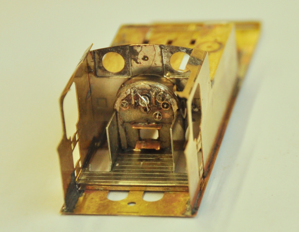
The bulk of this assembly starts as a single piece, that is folded up to form the cab floor, splasher sides and the bulk of the cab front. To assist the lamination process, jigs either side of the cab front have been used. Wire rods are slipped through the small holes in these to ensure that they are registered on top of each other properly.
The view below shows the laminations now sweated together and illustrates the square cut outs behind the cab front which are to enable glass/Perspex to be slotted in to represent the sceptical glazing. The view also shows the boiler backhead which is made from three layers of etch (not with a folding jig – yet!). I am pretty pleased with this as this is only 13 * 15mm in size, so the wheels on the backhead are only 2mm in diameter.
To be continued…………(soon too!).
No Point Hanging Around
Whilst I have not put any posts up showing progress with the boards for Glenmutchkin, progress is being made and the last two boards are essentially now finished. I am hoping that with one more day’s work which will mostly be to build up a carrying box for the final two, they can all come home.
In anticipation of this, I have been building some turnouts and a bit of the basic trackwork.
I am only able to do the turnouts which I am reasonably confident will not change shape when the track is finally laid out on the boards. In essence this means the crossings in the bay, the main line and the goods yard. I have also done one of the turnouts in the yard. So seven down, twelve to go including a slip!
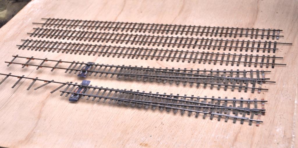
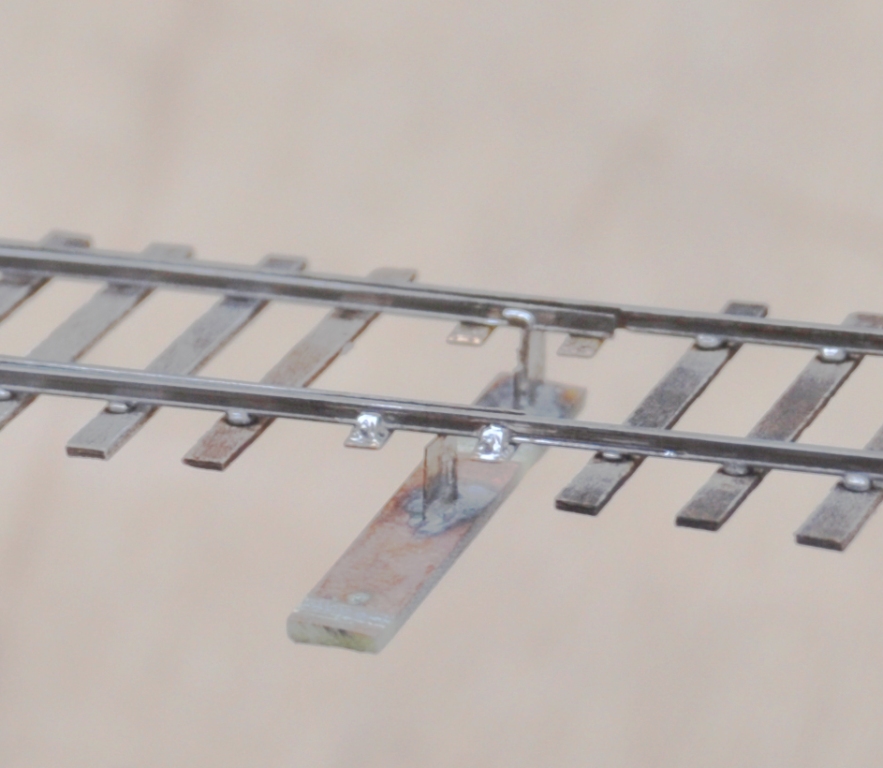
I have also developed my approach to TOU’s slightly from Portchullin. As a finished article they look like this:
You will see that relatively little of the TOU is exposed (and when it is painted it blend away further). Equally it is much more durable than most of the other options out there because the switchblade is held by both a wire strip but also to some brass strip that is tight to the underside of both the switchrail and the switchblade. By installing this strip in this location, the switchblade is held in a vertical plane much better than other solutions. I think this leads to better running.
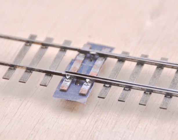
This is what it looks like as it is being assembled. You will see that in essence is it is merely a bit of copper clad below the switchblades, but lowered somewhat further due to the use of the brass strip. This allows the whole lot to be hidden below the boards.
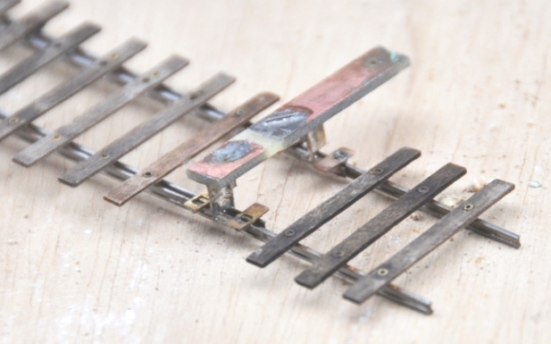
You will note the rather unusual arrangement of sleepers. This is called interlacing and was very common on many pre-grouping lines, including the Highland. I will expand on this in a future posting.
Bob Symes (1924 – 2015)
In a rare departure from my general policy of ignoring of topics beyond strictly modelling, I thought I really ought to comment on the passing of Bob Symes at the beginning of this week
.
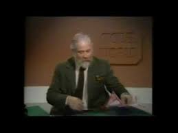
To those in the UK of my age, you probably will have first encountered Bob as the presenter of the Model World TV series in the early 1970s. This was a series of six (I think) episodes, each dealing with a different modelling subject; military modelling, ship modelling, aeroplane modelling and, of course, model railways. You couldn’t see the BBC risking BBC channel 73 with a series on making models now, let alone a prime evening slot on BBC 2 which is where I think these were aired. Most of the episodes are available on youtube (for example this one) and whilst perhaps the quality of modelling has come quite a long way in the last 40 years, I wonder if the charm that Bob seemed to impart to his interest may have been lost? And for you that really were there watching these back in the 1970’s, the opening music will instantly wipe away the years………….
Thereafter, I encountered Bob quite regularly as he was the president of my then local model railway club; the Astolat Club in Guildford. He would attend most of the Astolat’s shows and was always encouraging to the efforts of the juniors, such as myself, which was certainly appreciated. He would also have an open day at his house in the summer where you could get to see and play with his trainsets – and didn’t he have a few! It is not everyone that has what must be something like a 12 inch guage circuit in their garden; and gauge 1 circuit, and a couple of others besides and that is even before you get to his steam powered generator and water pump!

I still pass close by to where he lived quite regularly and thought I ought to see if I could get a further invite. Now the chance is gone. So rest in peace Bob, you definitely were an asset to the hobby.

The majority of these photographs are with thanks to Guy Carpenter of Gullwing Photography and he retains copyright of them. For more information please go to Guy’s website and for some more of Guy’s fine photographs of his visit to Bob’s house please go here.
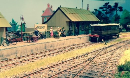
The Hundred of Manhood and Selsey Tramway
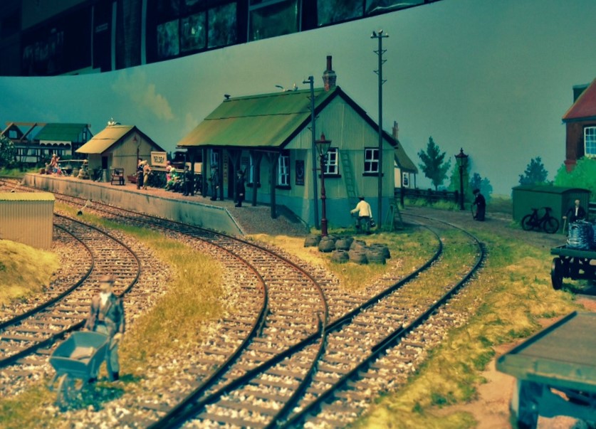
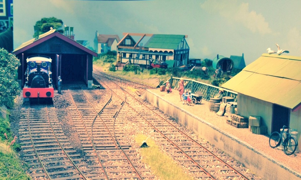
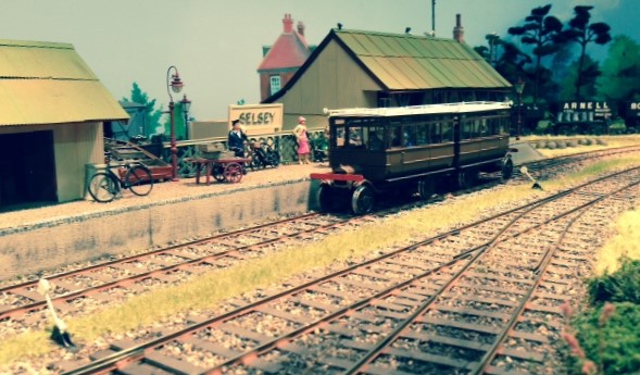
On Sunday, I got to play trains on something that is mildly different for me. This is a layout called Selsey Town which depicts the same on one of the best named railways you can imagine – the Hundred of Manhood and Selsey Tramway (you couldn’t make it up could you?).
This line was one of Colonel Stephen’s light railways; this being engineered by him, managed by him and largely owened by him at the end. The line was incorporated in 1896 and opened the following year. It ran from Chichester, which was on the LBSC coast line about 25 miles west of Brighton down to Selsey which was on the coast. It ran across predominantly flat ground but this was quite marshy (indeed, floods severed the line on a number of occassions).
In typical Colonel Stephens style, the line was a real hotch potch of cobbled together equipment that was patch, patched again and then patched some more to get it to go. The line operated without Board of Trade approval for its first thirty years on the basis that it operated exclusively on private land. My knowledge of the controls is that this can’t be true, but it certainly did not have approvals in place until much later in its life.
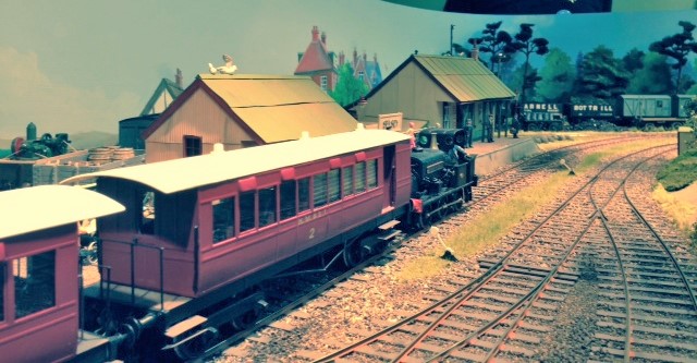
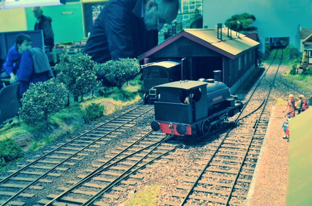
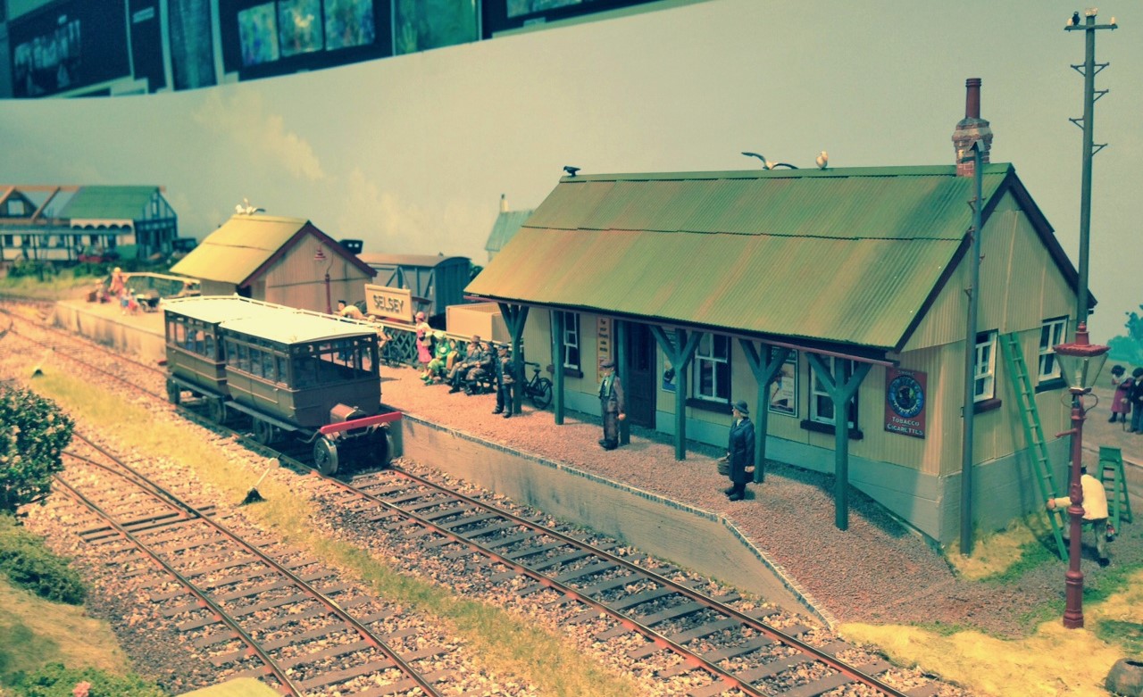
The line was famous for the first use of petrol railcars; something of a calling card for Colonel Stephen’s lines. These came in several different forms and on the layout a pair of them work back to back. There are apparently plans for a further pair; one of which will be a flat bad lorry. To bad if the compartment is full!
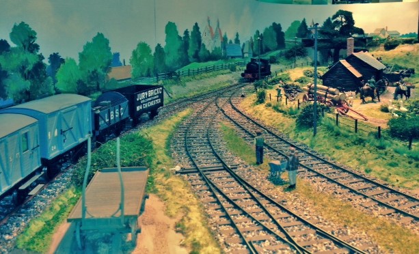
One rather curious procedure that happened on the real line was the some waht unorthadox mixed trains. On the outward journey from Chichester the wagons would be tucked behind the coaches but on the return journey they were sometimes propelled by the train, whilst the remainder of the train was pulled. Somehow, I don’t think the Board of Trade would have approved!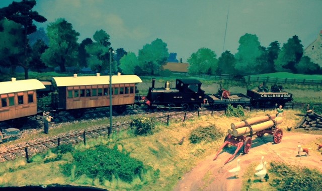
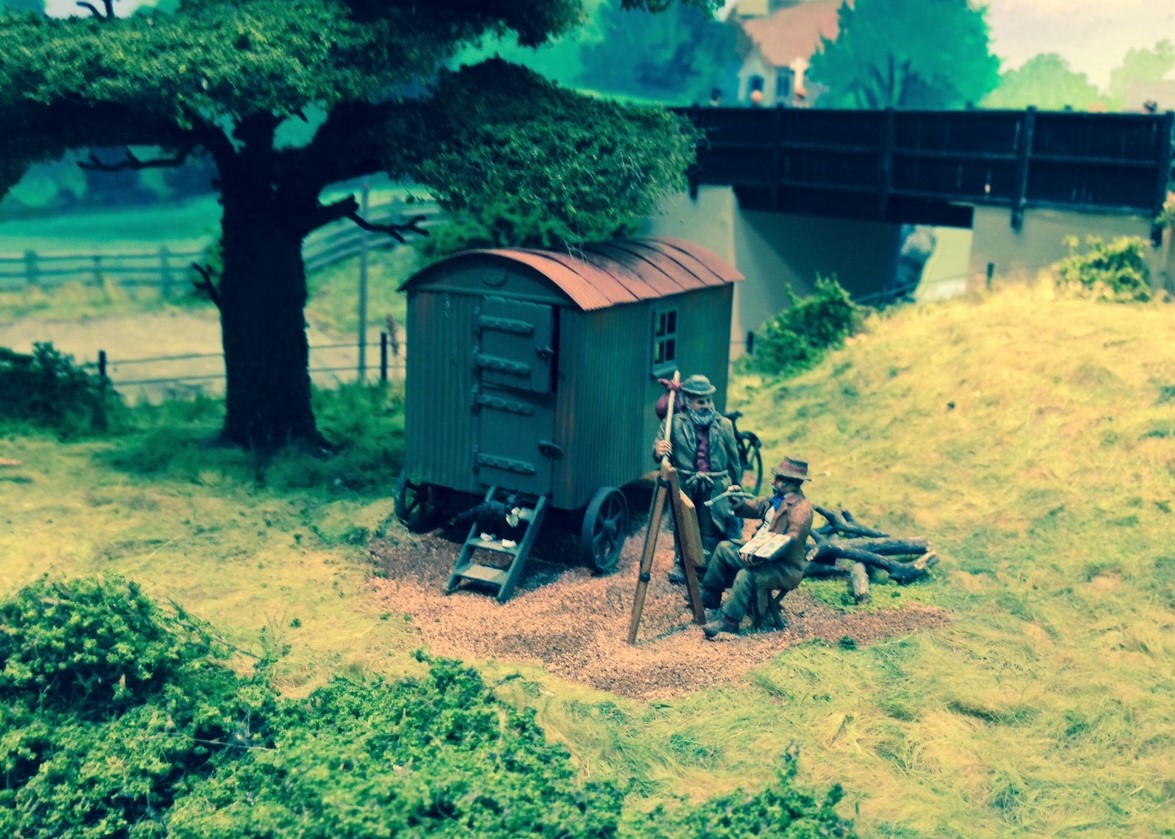
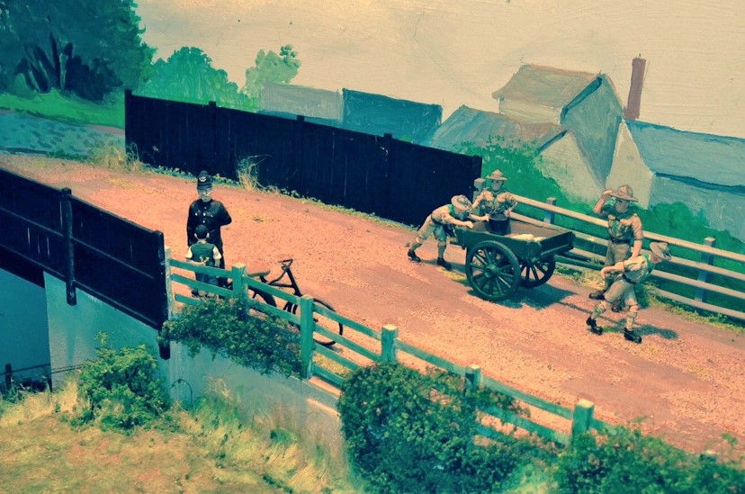
The layout was built by Keith Smith; although he was convalescing so was not actually there – thats why they needed a bit of assistance and how I bummed my invite! Keith’s pleasure is making the scenary and there are large number of very well executed people and cameos on the layout. Here are a couple; an artist being interrogated by a shepherd and a little boy going through a rather more severe interrogation from a police office – I wonder if Dixon of Dock Green will see the caterpolt behind the boy’s back?
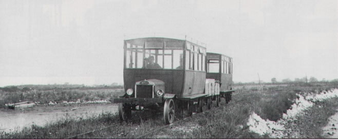
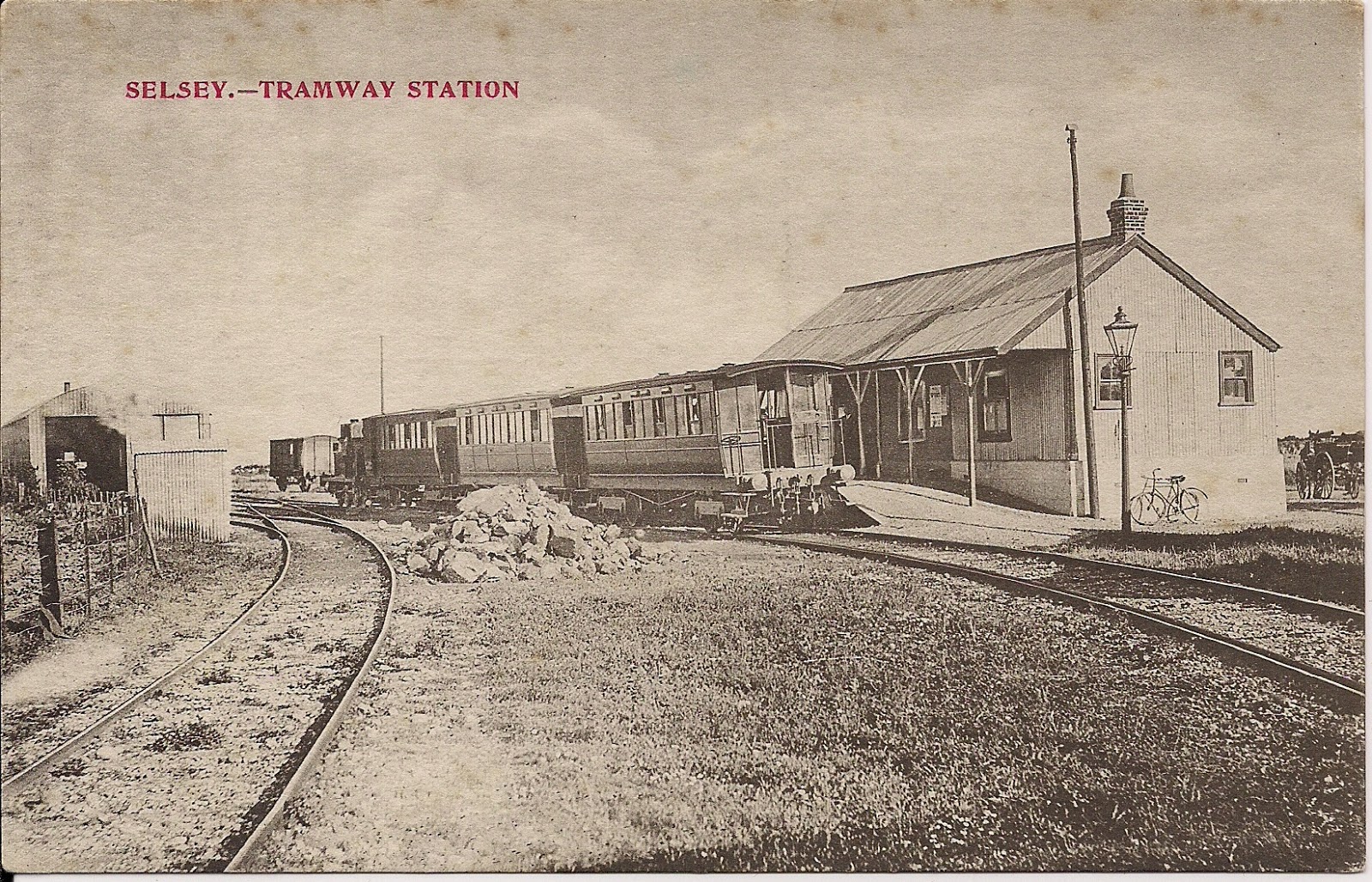
And finally, here are a couple of postcards of what the line lloked like in real life; with those Ford Railcars out in action. The line was famous for the poor condition of its trackwork; a point that can’t be disputed by the first photograph at least! The line eventually closed in 1935, a few years after Colonal Stephens died and now there is very little remaining of it.
Compare this!
NER Hoppers – Part 2; liveries
I have made more progress with the hoppers, having completed the main paintwork of these and also the lettering.
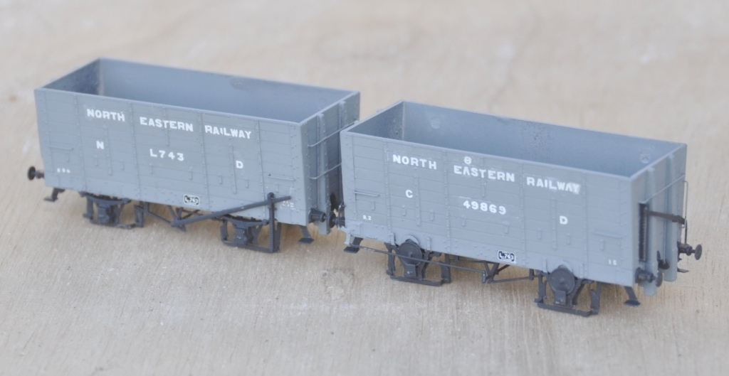
Both the livery and the lettering offer further opportunities for variety, which I have taken. First up are a pair of wagons lettered with the full legend “North Eastern Railway”; a livery applied on some of them upto 1903. This was a fair pain to create, as the full words had to be spelt out from an alphabet; even now I am not totally happy with this and a few tweeks to some of the letters is possible.
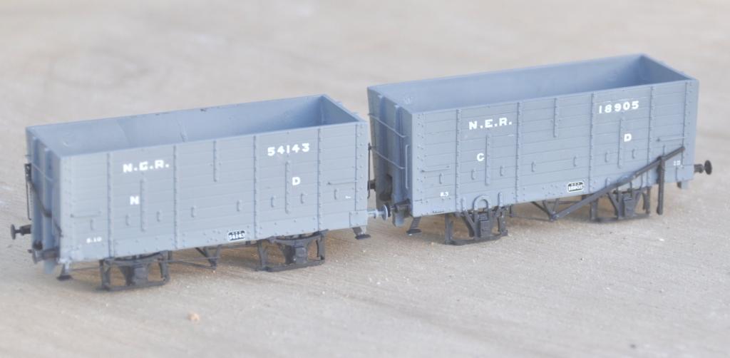
The most common livery for the period that Benfieldside is set (just prior to the first war), was the livery applied between 1903 and 1911 and the legend NER was used.
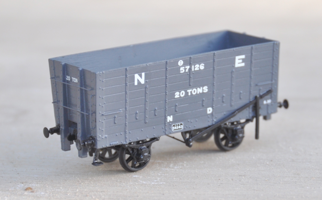
The final livery was on a darker grey and NER was dropped and replaced with a mere NE. This vehicle had a load designation on its end too, which appeared to be an occasional feature.
Once I have had a chance to tidy up the lettering, I will paint the interior a dirty black and speckle it with coal dust. I will also make a coal load. Then these need the application of grunge as I can’t believe that coal wagons were kept particularly well!
Christmas is the season for…………. jolly well finishing stuff off!
Over the break, I have been concentrating on trying to finish things. Like many people, I find it much easier to start a kit or project than it is to get it fully finished. Indeed, do we every truly finish our models – certainly not our layouts!
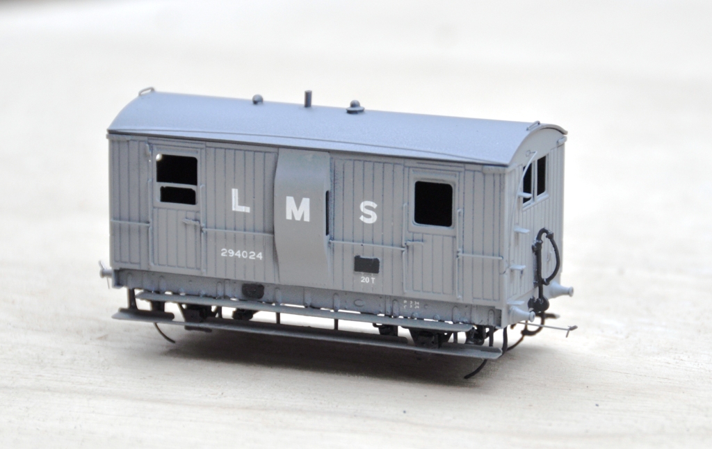
Back in March 2013, I completed a dia 39 goods break. These were the final Highland Railway break vans and it is not clear that they were actually finished prior to the end of the HR era. Given that I model in the mid 1920’s, I am quite content to do this in LMS grey which to date I have not seen the model depicted in! The main body painting has been completed and the van has been lettered but weathering, the interior and final detailing/glazing is still to be completed. Based on the Lochgorm Models kit with minimal adjustments (a few pipes below the chassis and sprung W irons in lieu of the compensation provided in the kit) this is what it presently looks like:
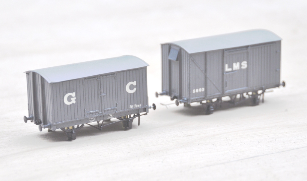
Also coming through the paint shops are a pair of vans. The first is a Great Central van build from a Mousa Models etched brass kit and the other is a LMS early standard van from an injection plastic moulded kit from Cambrian Models. Both are pretty simple models to build; the Mousa Models one was built as designed and no adjustments were found to be necessary. I only fitted springing to the Cambrian one and got rid of the rather too thick W irons in the process. Again the bulk of the painting is complete, but some dirtying work is definitely still required.
Apologies for the slightly squiffy photos; I left it a bit late in the day to take them and the light was poor. I have made a lot of progress painting the NER hoppers, but the photos of these really did not make it and need to be repeated. Something to post tomorrow I suspect!
