Category Archives: Workbench (other)

Let There be Water…….3 – Now There is!
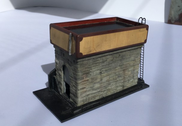
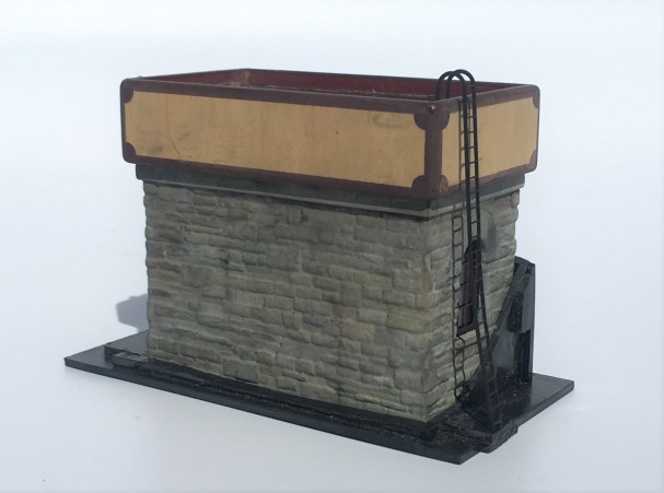
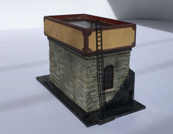
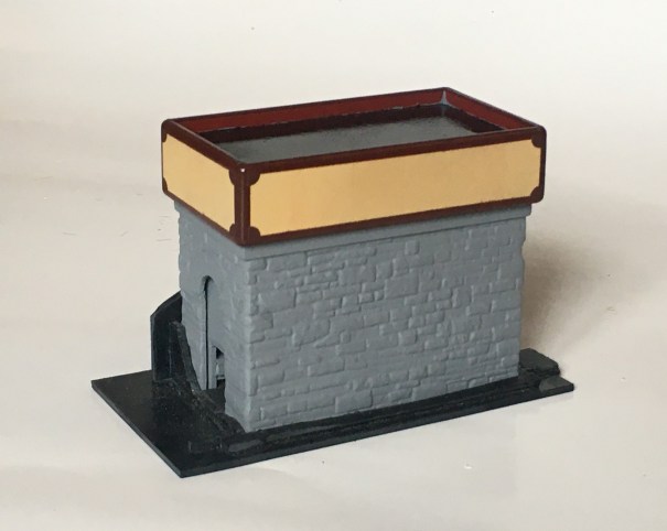
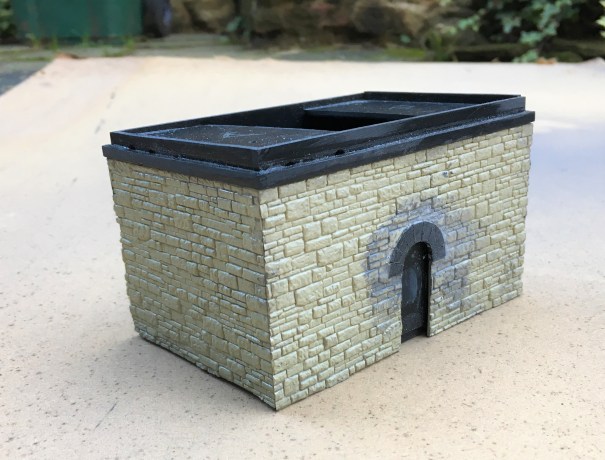
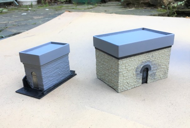
More progress has been made with the pair of water tanks and they have now reached the stage where they are effectively finished.
The stonework was painted by picking out each stone in different colours. I think there is a real art to this as when I see others do this, I often think the colour differences are unrealistically abrupt. I find the trick is to use a core of two colours that are close to the general colour that you want – in my case Humbrol Matt no 5 & 64. Put these in separate palates on a mixing dish and dip into these to create a combination of the two.
By selecting two relatively close colours, you can alternate from all one to all the other and any mix in between. Adding very moderate amounts of a stronger colour difference, in my case Humbrol Matt 66 and 62 which are a darker grey and a leather brown adds a bit of variety but in each case they still need to be mixed in with the two core paints to keep the toning consistent.
Even with this work the colours didn’t seem quite real, so I completed two additional steps. The first was to use some matt varnish that I knew the matting agent was a bit gone on – this gives a slightly translucent milky effect over the whole and drew the colours together a bit. The second was to use AK Abteilung 502 weathering powders – black smoke, ashes grey, gunmetal and rubble dust (primarily because these were the only colours I had!). These need to be used with care, as it is easy to put way too much on and you can’t generally get it off again! However, at low level and to the coal bank I have been pretty liberal with particularly the black smoke as such areas were far from clean!
The weathering to the water tanks was dealt with slightly differently, although it also started with the use of the acrylic varnish with the defective matting agent (that’ll be how I found out it was defective!). I then used a Humbrol dark grey was with downward brush strokes and then wiped off with a piece of kitchen roll, again with a downward stroke. A few additional marks, especially to the panel joints, with AK Interactive weathering pencils.
The water effect was another accident flowing from the defective matting agent – the milking was far from desirable on the black base coat of paint. Thus, I wiped it off once it was semi dry and I got most of it but where the remainder was still there, it added a bit of texture to the surface, as if there was a little disturbance to the water that affects part of the surface not the whole.
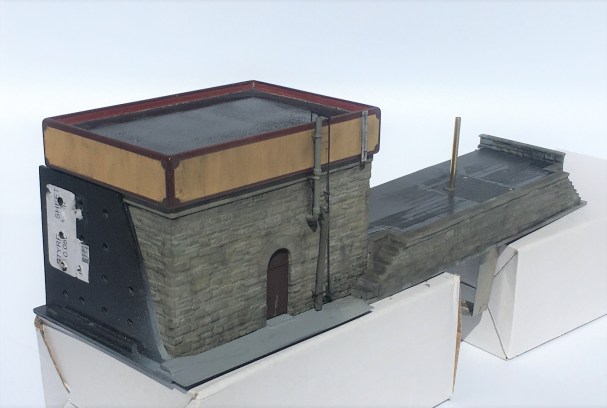
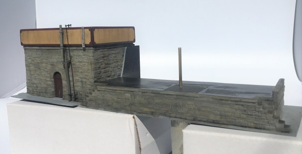
By reference to the prototype, I made a heating stove flue and spigot for the water bag from brass rod. To form the bends it was necessary to have a pair of additional tubes inside each other to stop the tube collapsing on the bend, The canvas section of the leather bag was formed by a piece of heat shrink sleeving but with a little 5 minute araldite in the centre such that as this starts to cure a degree of shape can be put into it and once fully cured it will stay in this shape.
The operating rod was based on that still largely apparent at Altnabreac and I have assumed this also had a ladder even if this has now gone. There is no watering bag to the smaller of the two water tanks as I propose to have some water columns, but that is a story for another day!
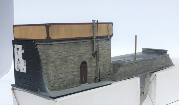
A further story for another day is the rather odd post sitting in the middle of the coaling bank; but that story will be fairly soon!

Benfieldside’s Missing Signal
When my friends acquired Benfieldside, it had suffered a bit of damage, notably to its signals – in essence it was this that got me volunteered for their restoration! One signal that puzzled us, however, was the up starter which was missing altogether and we could not unearth any photographs of it. Ultimately, we decided that it should be a two doll signal to also control the adjacent bay (which did have a signal, albeit inoperative) – so I have set to in order to fill this gap.
The line is set in Cumbria and is an imaginary westward extension of the Newcastle & Carlise line. In theory, therefore, it should not have the heavy cast iron brackets that the NER used. However, in reviewing the NERA’s signalling book, it became apparent that there were quite a lot of strays of signal designs, so I had an excuse to build one!

As this particular signal is going to be platform mounted, I did not need to sort out a mount for it and moved straight to the post and bracket, the latter being by MSE which I had in stock.
I then moved on to the prefabrication of a pair of dolls, each with slotted posts. This is made up of solid square section filed to a taper which is then cut and each end then has a tongue filed on it onto which flat plate is soldered either side to create the slots. I used a variety of temperature solders to ease this process but it was not easy – I did have one gum solid which resulted in a need to dismantle it and start again! As alluded to in the previous post, as these are slotted posts I had to depart from my usual practise of fitting the arms after painting as it is not otherwise possible to solder them to the spindle for the arm.

As mentioned in the last post, I came up with a bit of a dodge to successfully (well, in two of three cases!) to solder the arm to the spindle without gumming it up. By extending the ear that forms the point at which the operating rod attaches to the arm forward a bit (see the line below), it provides a point at which the soldering iron can be touched. If you use a slight excess of solder this allows the heat to transmit to the spindle and make the soldered joint.

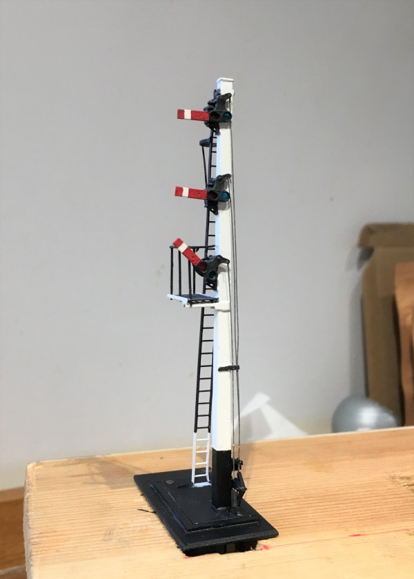
And this is what you get with a prefabricated doll, ready for the next stage of assembly.

And below of the pair of dolls now inserted to the landing.

Even at this stage, there is still a lot of building to do as there are handrails, the main ladder, steps and ladders to the dolls, the operating mechanism transferring the movement to the dolls all to do. In respect of the latter(I used rocking cams in this case – you can just see the use of some handrail knobs as the bearings in the photos below, the cams will be fitted after painting.

Slightly peculiarly, the NER built their landings in front of the arms whereas all the other signals I have yet built have these in the rear (excepting gantries, which can be either or both!). This view shows this most clearly.

The main ladder is not visible in the views as I have made this detachable because it is much easier to spray paint these (and better, it is not easy to get a thin coat of paint by brush application and it thickens up the fine detail of a ladder too much.

The grey primer is pretty cruel to modelling efforts but on the whole, I am pretty chuffed with this!
Tatty’s Top Tips – Signals
A mere three weeks ago, but a lifetime in the past now that we are in the middle (or more worryingly, perhaps just the beginning) of the Covid-19 crisis, I was a demonstrator at the joint EMGS/Scalefour Society skills day. These skills days are not really exhibitions and are instead aimed at passing some skills on to the visitors – thus they are primarily a hall full of demonstrators with only the odd layout or two to break up the rows of desks.
Here I am, in a shockingly creased shirt (!), and as you can see, I am demonstrating signal construction. I am pleased to say that at the skills day I had a solid stream of people engaging with the topic all day; so much show I had to pull down the shutters for a brief lunch as otherwise I really would not have stopped all day!

By way of preparation for the event, I thought about what I have learnt about building signals and distilled a list of my top tips. These proved to be the cornerstone of my conversations with people at the Skills Day so I thought it was worth repeating them here on the blog.
Planning Ahead
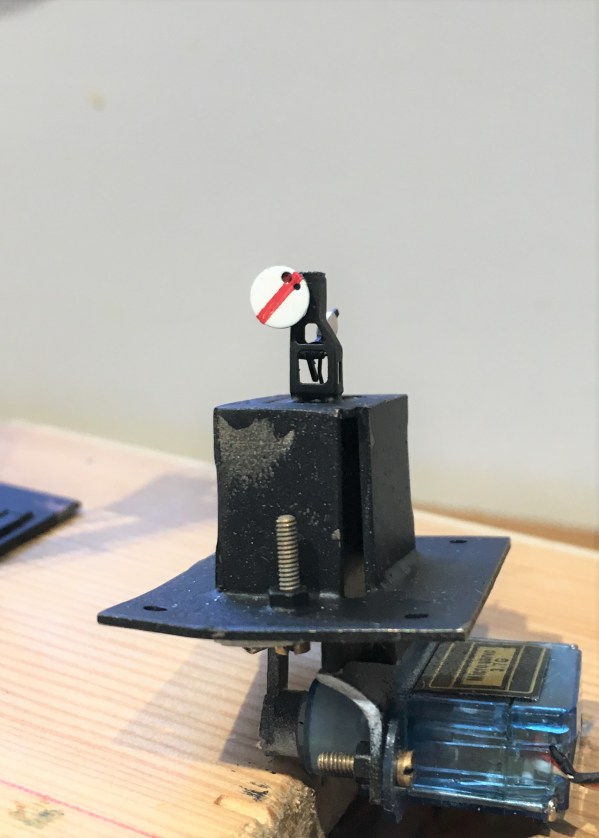
- Conceive how you are going to mount the signal; where and how, what is above the ground or below the baseboard – which might well mean you also need to;

The base and mount for a two movement servo controlled signal
- Decide how you are going to operate the signal, how is the drive mechanism to be mounted and what does it need to be connected to mechanically/electrically;
- If you are going to illuminate your lamps, you need to decide how you are going to run the wires to the LEDs or fibre optic cable. It is possible to use the post as a common return but you still need one wireway;
- Consider how the movement is to be transmitted (especially bracket signals) and how you are going to replicate this? Multiple movements in close proximity to each other can lead to interference, compromises to reduce this risk are sometimes desirable (especially for triple or more movements in close proximity);
- Conceive how you are going to paint and assemble the signal before you start – it is generally easier to paint arms and ladders before you assemble them so it is possible to create sub-assemblies to be attached later – the touching in of local areas of damaged paint caused through assembly is a small price to pay for the ease of painting the remaining areas;

A Southern rail built home signal; the post was formed of two pieces of nickle silver rail.
Construction
- Tight, tight, tight – the most important part of building a signal is to keep all holes of operating parts as tight and snug as possible as slack leads to sloppy movement;
- You will use a lot of fine drills, down to 0.3mm, and a good quality pillar drill will mean you break rather fewer of them!
- Use the file up the length of the post not across it as much as possible – the files leave less scars and any that do occur mimic the grain of the wood;
- Pre-form or pre-drill elements such as balance weights, holes to the posts or landings early on before they are assembled when it is easiest (well potentially!);
- The prototype of most of the components to a signal are pretty delicate with fine sections; thus, to capture their character these needs to be similarly fine, however:
- There is a trade-off to make with the operating components such as balance levers which are typically best made over scale and with laminated brass to give them more strength;
- Generally, build the bigger more robust elements first and potentially alter the build sequence in the light of thermal mass and whether adjacent items might be disturbed by later additions – consider using different temperature solders and prefabrication of elements such as dolls with all of the lamps/landings finished;

A prefabricated doll and arm – I wouldn’t normally fit the arm until after painting but this is not true for slotted post signals
- Don’t use the flat etched ladders, they are too flexible to look real. Either use the built up versions or solder 0.3mm wire on both front and back of stringers and file the outside face flat – they look more realistic and are more durable.

A flat etched ladder with 0.3mm wire being soldered to the stringer
- Lots of delicate parts and complicated sections means that ultrasonic baths are really helpful for cleaning without damaging elements;
Slotted Post Signals
- Not the easiest because of the need to solder the arm to the spindle inside the slot. Use a laminated piece to the ear that is the point at which the operating rod attaches to the arm and extend it cross the back of the arm by 3mm so that it is would project beyond the slot slightly. Be liberal with the solder but make sure that the rubbing faces are cleared of any excess. Wrap the arm in cigarette paper and insert it into the slot. After the spindle has been inserted, touch the cigarette paper with light oil and allow it to soak through. Then put a little flux on the laminated ear and apply the iron. The heat will transmit along the solder joint and reach the spindle.
Operation
- Protect the signal from excess throw; they are delicate – therefore set the servo up to an approximate centre point through before connecting it to the model;
- Leave room to be able to see the signal as you are setting it up, otherwise it takes ages and a lot of bending under the baseboard;
- If you are going to illuminate your signal, understand what the right colours would be – oil lamps are relatively dim (so you need to resist down the voltage) and quite yellow (so modern LEDs need to toned down).
Dimensions
Dimensions were not standardised even within a company, let alone between, so offering directions on dimensions is dangerous – all I will say is these dimensions are commonplace:
- Single post wooden signals – 6” square at the top and then tapering out 3/16th of an inch for each foot of height (1.5% or so)
- Wooden doll posts – 7” square at top and tapering as before
- Main post for wooden bracket signals – 10” at the top and then tapering as before
- Single post tubular signals – 5 1/2″ to the upper portion and 6 1/2″ to the lower portion. The height of the lower portion varied with the height of the post (for details, see LMS journal no 4)
- Arm – centre pivot – 1′ 6″ from the top of the post; second arms 6′ 0″ below that;
- Spacing between dolls – 6′ 0″ or 6′ 6″ (less for shunt arms)
- Height of handrail to landings – 3′ 0″
A GER three doll bracket signal
……part 2")
Let there be water (and coal too)……part 2
One of my pet hates on model railways are buildings that float a fraction above the ground because they have been plonked in situ, not bedded in. For me, it completely destroys the illusion and I can get quite wound up about it when I see it (…..and it is pretty common, so this is fairly often!).
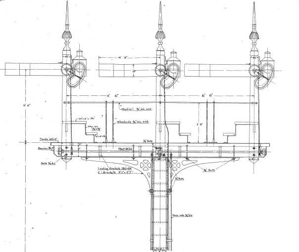
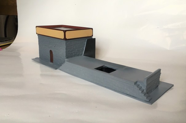
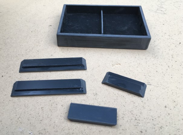
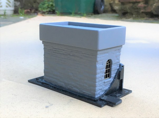
Occasionally, I actually do attach the building to the baseboard and “scenic in” the ground around them but more normally I construct a base into which the building sits. This gets embedded permanently and then the building sits into a slot that is formed into it. I have also seen the building being built in two parts, with the base being affixed to the ground and the building slotted onto them. Peter Bond did this for me with the signal cabins for Portchullin. This is the base for the larger water tank:
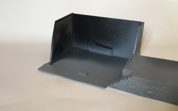
The large water tank is more prominent as it is located closer to the baseboard edge and is to the rear of the main focus of the MPD area, the trackwork between the shed and the turntable. It is also adjacent to the coaling bank and as a result I decided to make this now and as part of the base for the water tank.
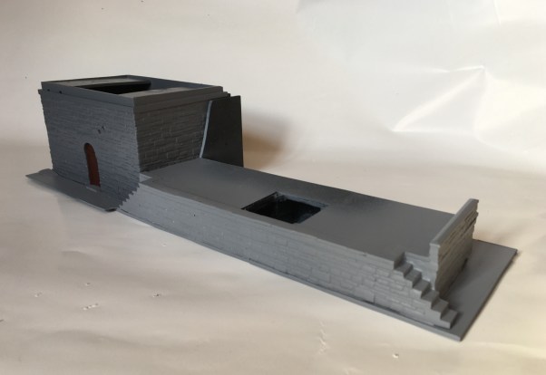
The smaller of the water tanks is designed to mask a baseboard joint in a rockface/embankment. The base (below) will thus be split into two halves when it is fitted, each sitting on adjacent boards – a neat way of not having the San Andreas fault line running through a rock face!
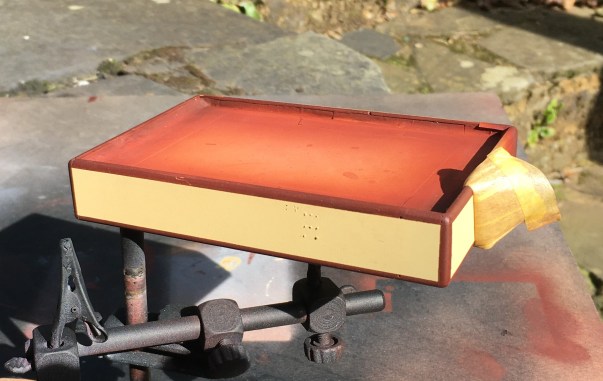
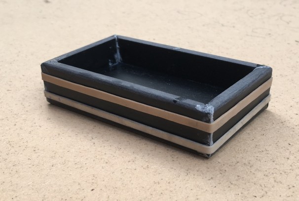
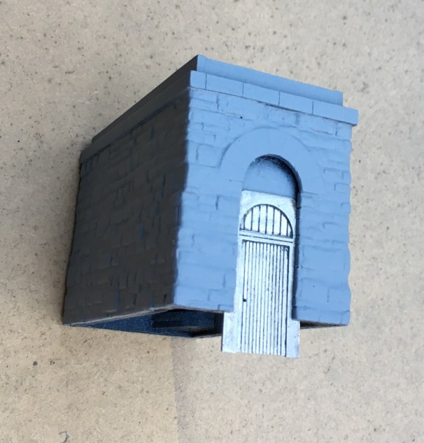
I have also started the painting of these, which had a fairly characteristic design with the border in a red/brown and a cream central panel. It is important to recreate this and as it is fairly eye catching, errors will be instantly visible.
The straight edges weren’t too difficult to achieve with masking tape; initially the horizontals and then the verticals a day later. Peeling back the masking tape was a thrill to see if it worked!
The scrolls at the corner was a concern throughout the construction of the water tanks but I did hit on an idea I think is rather nifty. I sprayed the same red/brown on some transfer paper (thanks Chris!) and once it was dry, used a domestic hole punch to create disks of transfer. I then cut them into segments that were a bit bigger than a quarter of the disk. They were then applied as a transfer to each corner.
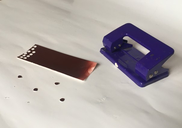
Actually, it was pretty easy once I got going – I definitely spent longer thinking about it than I did doing it! I am pretty pleased with the outcome, much neater than my hand could manage!
The rather prominent hole in the coal bank will be the subject of a future post, as there is something a bit different planned for this!
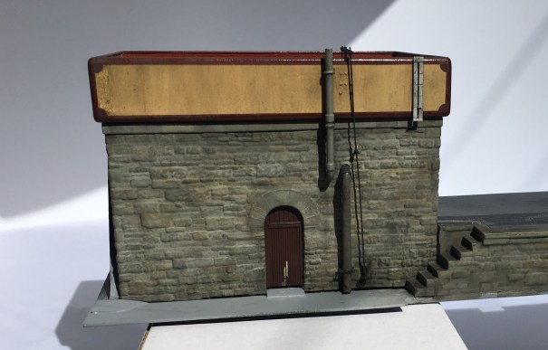
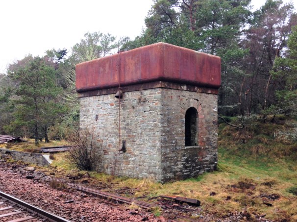
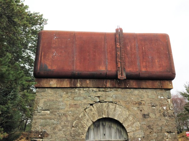
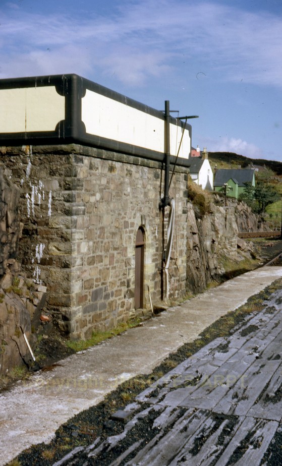
Alnabreac Water Tower – the Prototype
The smaller of the two water towers I am building is a model of the tower that the Highland Railway built at Altnabreac. Altnabreac is around 12 miles from the nearest paved road so even though it has not been used for approaching 60 years, it has proved too expensive to realise its scrap vale.
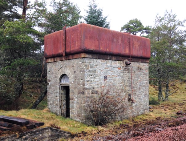
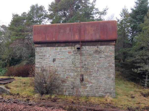
What is possibly even more remarkable, you can see the paint – including the detailing at the corners – which probably dates from the LMS era; how much original pre-1948 paint is still out there?
Being able to get up close to the tank, it can be seen that it is made out of sections; there are quarter segments for the corners and then straight panels for the sides. They obviously came as a kit of parts and could be built to a size to suit the requirement. Thus, I note that the Altnabreac is the same width wide as the Kyle tank was deep – so I can determine how many panels were used to make the Kyle version. Whilst the lines are fient, they are there and I will replicate them with a hint of a score on the plasticard.
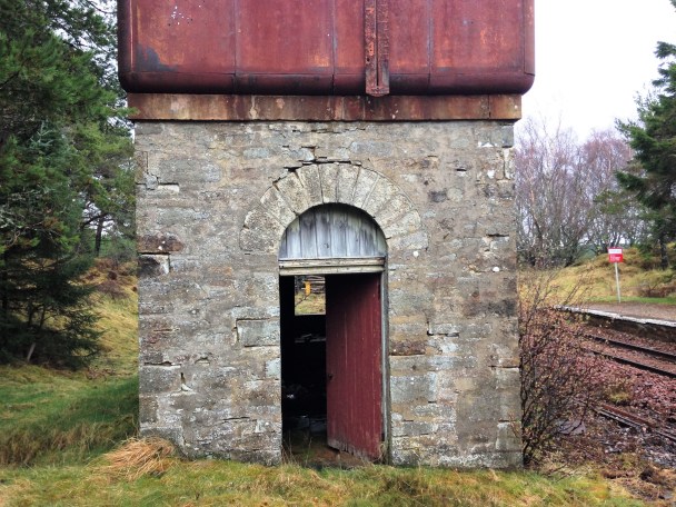
A float inside the tank was used to transmit the water level to this gauge on the exterior.
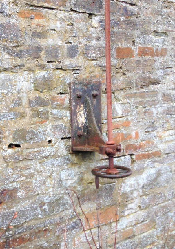
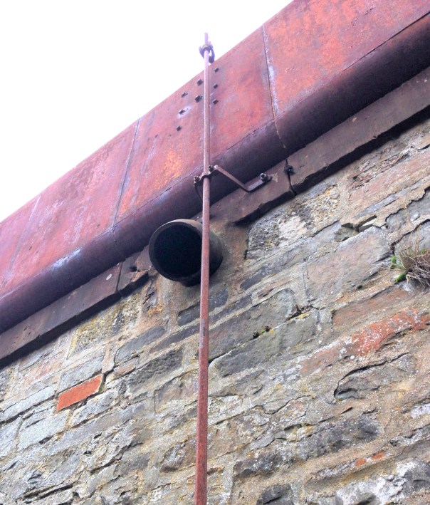
The tank as a whole is remarkably intact – the only elements I can positively identify is missing is the delivery bag which will have been of hessian and the wooden windows. However, I suspect there are two other elements that have now been removed. There was probably an access ladder at one end to reach the interior of the tank but leaving it in situ would to be dangerous, hence its removal. Furthermore, there is no sign of any heating to the tank. Whilst the largish body of water will have taken a while to freeze, the region around Altnabreac is well-known for its cold temperatures so I suspect there is a boiler inside with a flue through the tank. The outlet valve is controlled by a wheel at low level connected with a rod with a thread at its head. This connects to one end of a lever that has a threaded nut in order to transfer the movement into the interior of the tank where the valve is located.
A drawing of the water tank can be found at this link: Altnabreac Water Tower or if you are a member of the Highland Railway Society it will be in the next Journal and subsequently from their drawing service.
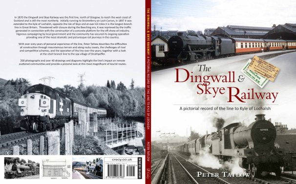
The other water tank I am building is a model of Kyle of Lochalsh’s water tank. Eddie Bellis drew this and his drawing is in the November 1975 edition of the Railway Modeller. There are couple of pictures of in LMS Engine Sheds: Volume 6 by the Oxford Publishing Co. The only other Highland Railway water tower that has been drawn that I know of is Garves, which Henry Orbach drew – it is in a 1950s Model Railway Constructor or was reprinted in my fathers The Dingwall & Skye Railway.

Let there be water……..part 1
Part of the concept of the back-story for Glenmutchkin is that it is at the end of a long line so that locos need to be serviced and it was also at the foot of a steep gradient, so trains need to be banked out of the station. All this is creates a lot of thirsty locomotives that would have needed servicing and attention – so it will have a busy motive power depot.
The Highland Railway’s water tanks tended to be of a similar style with a tank made of sectional components and rounded head, base and corners. There is nothing available from any of the manufacturers so it was obvious these need to be scratchbuilt.
There remains one tank of this type still in situ, at Altnabreac which I will describe in the next post. In addition to this, there are drawings from Eddie Bellis of the Kyle’s water tower and also of Garve by Henry Orbach. I have elected to build a pair – one of Kyle and one of Altnabreac (the latter being the smaller).
Kyle’s water tank from the early post steam era. Photograph with permission from Armstrong Railway Photographic Trust, JM Boyes collection.
Starting with the tanks, I laminated a series of strips of plasticard to the right height and then used a belt sander to put the chamfer on these before then making them up into a box.
As with most of my stone buildings, I use Wills random stone plastic sheets; now available from Peco. On far too many occasions I see this used with panels butted against each other; either on corners or even worse on the flat. Unless the stones are toothed into each other, this screams as being incorrect even to a layman. Therefore, it is best to form corners either from a sheet cut vertically and then chamfer the inside faces so that the coursing is retained for its full length even on the cut face.
This means that courses line up from side to front without any silly jumps, as can be seen below. This technique can not be used in all examples and sometimes it is necessary to actually tooth panels into each other by cutting corresponding dog teeth into adjacent panels.
I find that the mortar courses on Wills sheets are a bit too deep and because lots of others use it its pattern is a little too obvious; so it looses its realism (or maybe I am just so sad that I can tell a material by its stone coursing!!). I get over this by part filling the mortar courses with a plastic filler – which is basically dissolved plastic in a solvent carrier (lovely and smely!). This tends to distort the sheets as it is only applied to one side so I first laminate the sheet to some thick (1.5 or 2mm plasticard). Due to the volumes of solvent to be sloshed around in constructing buildings in this manner, it is important to allow for the solvent to escape – regretfully I have a number of coach roofs which many years later have mushy sections where the solvent has been trapped and has distorted the plastic in its efforts to cut through it and escape! I thus drill regular holes or slots in the backing plasticard, which you can see here:
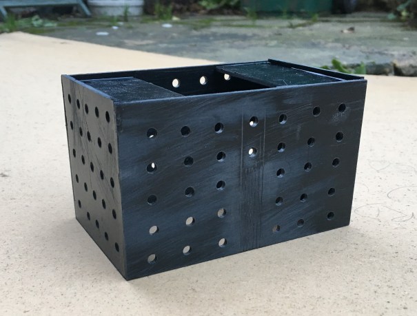
Whilst the desire to mask the coursing pattern on the Wills sheet might seem a fair amount of bother given the need to reinforce the walls with an inner laimanate, I think the effect is worth the effort. A blast of grey primer shows that the coursing and texture of the stone is retained but equaly it does not look like everyone else’s!
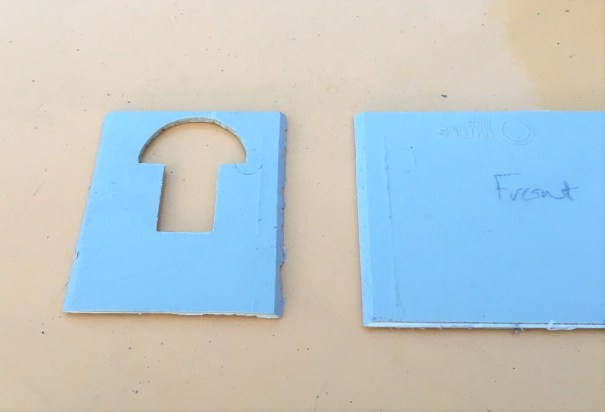
The use of the laminations does give the advantage that slots for window frames and doors can be created. These allow an etching to be slid in, either from below or behind. They can be slid out again for painting and make this aspect a breeze to do.
And this is where they have got to; the guts of both done but with a chunk of detailing and some basework still to be done.
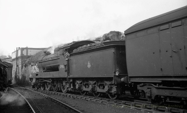
But lets sign this post off with a fine HC Casserley picture of a Superheated Goods using the MPD as a headshunt in the early 1950s. This photograph is used with permission and is now part of Ernie Brack’s collection. He has a substantial on line collection of photographs (including the JM Boyes collection) with a good proportion of them being of the Highland’s system – you can loose many an hour in his flickr site – this being a link to his Dingwall & Skye album.

Putting a Backbone into a Shed
The advantage of a railway company using standard building designs is that you can get to use them more than once. Thus Portchullin’s goods shed will be getting to have a new lease of life on Glenmutchkin.
I think my goods shed is the oldest model that I still have and over the years it is fair to say has suffered. Some of this is simply the thirty six shows that it has done with Portchullin (hell………thirty six shows…….!) and almost as many years, as I was about 17 when I made it. However the main issue was the manner in which I built it, with minimal bracing over the top of the entrances. This has lead to it breaking its back and despite several attempts at repair, these have never been long lasting. So it is time to do it properly to allow its reincarnation on Glenmutchkin.

The key to the repair was to introduce a metal skeleton frame inside the model to strengthen it – particularly across the rail doors. This is something I now tend to do at the outset with any largish building I build to contain warping. The frame is invisible from the exterior – the view above shows the frame that I made with the first side attached.

The frame was made with some 3mm square and oblong section brass, with gusset plates – there was a fair amount of metal so it got close to blacksmithing at one stage.
Once the frame was inserted, the model was given an overhaul to repair the other dinks and marks that it has acquired over the years. There were a fair few, as can be seen.

I also to the opportunity to install gutters and downpipes; something I had been meaning to do since I was 17………a bit of a shameful shortfall, given I am a chartered building surveyor!


I am pleased with the results and the model is now much more robust so it should do at least another 36 shows! Whether its owner can will be kept under review!
My goods shed is based on the Orbach drawings of the shed at Garve (the August 1952 edition of the Model Railway News). The prototype was swept away in the 1970s and whilst there are a pair of the smaller sheds still remaining (notably at Brora), there are no longer any of the standard Highland Goods sheds left. The last to go was in Golspie about two years ago and I did manage to both photograph and measure it before it went. Here are some views of it before it was demolished:


Controlling Bottom Works Sidings
Followers of this blog will probably be aware that I share some of my model railway escapades with the two authors of the blog OTCM. Both of the authors are in the process of putting together entries into a competition to build cameo layouts being orchestrated by the publishers Titfield Thunderbolt. Cameo layouts was the topic of a book written by Ian Rice and seeks to describe a small layouts seeking to use presentation techniques to capture a slice of the whole in a convincing manner.
To be fair to Oly, his entry is largely complete as long as he does not seek to tinker with it too much(!), the same could not be said for Chris’s entry – titled Bottom Works Siding – so he has some catching up to do! To assist Chris I offered to make his signals and after a few weeks of work we have reached the point where they are complete.
Chris’ model is based on the GCR’s route over the pennines at its Yorkshire end. It will represent a set of transfer sidings from the Woodhead route electrification to a industrial line serving a coking plant – so I suspect we will get to see a fair amount of grot in the finished article! Its signals are LNER or BR(E) practise which is mildly different to what I have built before in some regards but not others as there was a lot of standardisation between the LMS and LNER (and BR more or less adopted LMS practise). So first up (above) is an LNER standard wooden post with replacement BR miniature upper quadrant arms. The post is a piece of brass square section that I filed to a taper (hard work) with predominantly Masokit’s fittings (which I found to be notably better than MSE’s equivalent).
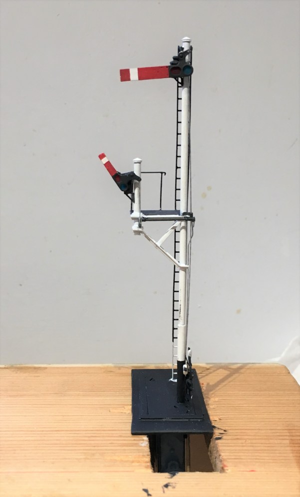
This one is effectively a standard LMS/BR tubular post signal (apparently with brewer’s droop – sorry!) with a small bracket that has another miniature arm signal to it. This is assembled with a combination of tubes and angle section from Eileen’s Emporium, along with some more Masokit’s arms.
And finally a miniature ground signal – which despite being startling small was not actually all that difficult to build – it being based on a excellent little etched kit from Palatine Models.
As a result of a lost camera, there are not really any meaningful photographs of the signals being created but fear not, I still have a few to go for Glenmutchkin, so there will be some to come! In the meantime, and to prove that they really do go, here are some videos.
In the fullness of time, I dare say we will get to see these in situ, so why not subscribe to Oly and Chris’ blog, to get an instant notification?
The Glenmutchkin Pharmacy – Part 2; Beware Roofers!
Progress with the Pharmacy building has continued and the roof is now nearing completion. I preferred using sheet metal (in this case nickle silver) for roofs as I find it is the easiest was to then include gutters. In this case, I designed the roof as a simple fold up etch and subsequently the gutters were formed by half round section from Eileen’s Emporium.
One of the pieces of artistic licence I went for relative to the real Kyle Pharmacy was to elongate the building slightly. This was partly because the prototype was a bit square and squat but also because I fancied including a decorative ridge piece. The Victorians and Edwardians did love a bit of decoration and this included the details to their buildings. There were numerous contemporary catalogues of architectural bits and pieces from which to choose from and I liked the idea of something pretty – especially given that this model will be right at the front of the layout. So I created a design of my own and etched it; along also with the characteristic sign that is so prominent in the photo in my last post.

Those that looked carefully at the prototype photograph in the last post will have noted that the roof slates were diamond shaped. These were, in fact, asbestos slates and were quite a common material for pre-fabricated and simple buildings such as the Kyle Pharmacy. Clearly they needed to be modelled but I did no fancy my chances of cutting the odd couple of thousand slates consistently. I toyed with getting some laser cut or cut on a silhouette machine but then had a brainwave – pinking shears.

For reasons I don’t quite know, dressmakers use these to create zigzag cuts and even better, my wife had a set. However, she spotted me taking a look at them which meant I had a very firm talking too and was immediately banned from using them!! Researching them on the internet showed that they come in a variety of pitches but be warned not all of them have 90º serrations. I did find a set with a 4mm pitch which was a bit less than the 5mm that I thought was scale for the Kyle Pharmacy but as this equates to a 12 inch slate, I thought it was plausible and not a bodge too far. As you can see below, they produce a neat and consistent serration.

I cut the slates from plain paper in strips which I then sprayed a mid-grey colour because I felt that asbestos tiles might be a bit lighter than normal welsh slates. I deliberately allowed a tiny bit of inconsistency of colour to creep in, to provide a little texture to the roof. However, painting them was not easy as the air of the airbrush sent them flying – so I had to create a cradle to mount them in for spraying.

Once painted, I secured them with spraymount and carefully set them out, with the point of the diamond to the row above meeting the apex of the one below.

It takes some time (around 2 hours for a fairly small roof!) but I think the effect is quite convincing. I find the the best effect to make it look natural is to lay the slates as consistently as possible – you don’t achieve perfect consistency and these small imperfections end up making it that little bit more. Deliberately introducing inconsistencies tends to look a little contrived; including in this case my slightly differing shades, however, this was expected and can be overcome.

The blend the colours together, I washed the slates with artist’s acrylic always ensuring that the brush stroke was down the roof to mimic the flow of the weather.
I also formed the ridge and hip flashings with cigarette paper which I had first sprayed with grey primer and then secured with more spraymount. This was laid over 0.6mm brass rod to give the central lead roll effect – this was secured in place with superglue. I initially tried to make the lead flashings in sections so that the correct laps between one piece and the other was achieved but I never got close to a neat or believable finish. Thus I ended up doing this in one piece per run.


The front signboard will need some more work yet (partly because I have damaged it!), which will feature in a future post as I am going to have a bash at producing transfers.

The Glenmutchkin Pharmacy – Part 1 The Etchings
It is a fair time since I built my last building, so feeling that it was time that I rediscovered my mojo for architectural things I have made a crack at a building that will be a fairly key feature on Glenmutchkin – its pharmacy .
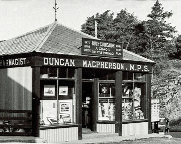
This is inspired, and largely a facsimile of, The Kyle Pharmacy that could be found on the approach to the ferry pier. Or at least it could until the 1970s when it was swept away to make a larger car holding pool for the ferry. In addition to being a characterful building, as you can see below, the real pharmacy at Kyle was a key part of the local community and I wanted to capture this feature in Glenmutchkin.
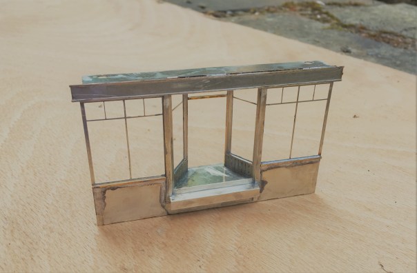
The pharmacy building is going to be located on the most prominent position at the front of the layout, so it definitely deserved some time being spent on it. Taking Peter Bond’s advice, it is going to be assembled in components which will make painting a great deal easier but rather than using plasticard throughout as he would have done, I have arranged to have the shop front and bay etched. I did so as I concluded that getting the slenderness and crispness of these was going to be key to get the feel of the model convincing. Peter is a professional architectural modeller and bending plasticard to his will is therefore his stock in trade – not quite so me!
So these are the basic etches back from PPD:
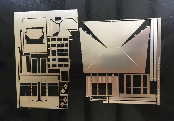
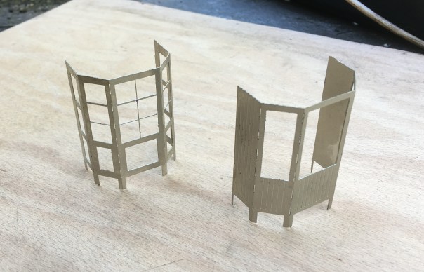
Some of the bay assemblies and the bay largely completed:
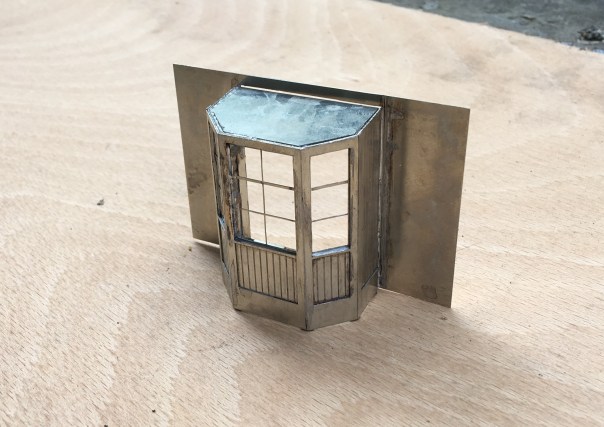
The real value of etching the components can be seen in the shopfront – I at least can’t get plasticard to look like this!