")
Stags, Steam and Steel (Lots of Steel…….)
Being a little alternative (a.k.a. railway enthusiast), when it comes to preparing for a friend’s nuptials, the flesh pots of some poor unsuspecting city do not come up to scratch. Instead, when Chris (of OTCM) decides to have a stag trip, he chooses to go around a grimy steelworks – well you wouldn’t you?

In this case, we went to Scunthorpe Steelworks where there is not only a substantial private railway (the largest in the UK, I beleive) but also an active preservation movement that operates on the system. This is the Appleby Frodingham Railway Preservation Society and they operate public services many weekends during the summer months and also charter trains throughout the year. For quite a moderate sum of money (if there are 15+ of you), you can have a private train take you around the majority of the network.

As you can see, first class is not an option for the tour but then it really would not have been fun if it were. Foolishly, we felt it was not right to fire up the stove in the van; the others in their van did and given how chilly it was they were the smart ones!

Our steed for the day was an Avonside 0-6-0 T which was one of two steam locos “in ticket” at present; the other being a rather pretty little Peckett, although its ticket runs out early next year so get there quick if you do want to see it in action.

The society also have a number diesels including this rather claggy Yorkshire Engine Co Janus which fumed us out when we were allowed to open the throttle in the shed, as you can see!

However, when out on the steelworks lines, these have to dodge the steel company’s quite numerous trains which are typically hauled by these – ex Norwegian Di 8’s. These had been delivered to NSB in the mid 1990’s but found to be under-powered and a little prone to catching fire. So when their traffic flows changed, they were sold for use at the steelworks her in the UK. Most are still in use, although a couple have been cannibalised for spares to the number is reducing.


The system is most extensive, amounting to over 100 miles of track and winds its way around furnaces, rolling mills, a coking plant, slag heaps and very extensive sidings. There was enough route mileage to keep us amused for the greater part of the day.


A steelworks is not the sort of place that is on my day to day circuit, so it was fascinating to see such iconic structures as the blast furnaces. There are four at Scunthorpe, all named after english queens, although presently only two are in production.


The steelworks is very much still in production – evidenced by how hot the torpedo slag wagons or those that were carrying fresh ingots. The heat haze coming off them does not show in the pictures but you could really warm your hands as you passed them at 40 feet away!


The trip is well worth the effort to do; even if you don’t have a stag to take along with you.
And besides, Scunnie is not too far from Sheffield were there are the city flesh pots if you want a combined outing – and if we did, that isn’t going to make it onto this blog!

South Hants Model Railway Show
In just over a week from now, I will be down in Portsmouth for the South Hants Model Railway Club’s annual show. Despite being a one day show, I find the show to be a good quality finescale show and the crew down there are very friendly, so it is definitely worth visiting. You can find details of the show here.
I will be assisting in the operation of Benfieldside, which I have illustrated on this blog in the past but it is worth looking at some of the pictures again:
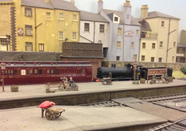
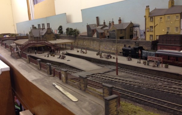
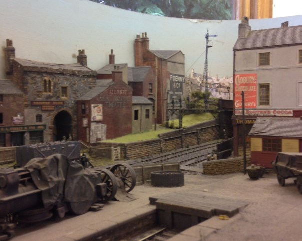
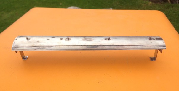
I can assure you it is worth coming to the show to see this alone; and you might even find my latest construction effort – although probably still shiny like this. This is a D&S Models NER auto-carriage and really needs a sister to work with it but that will have to wait!
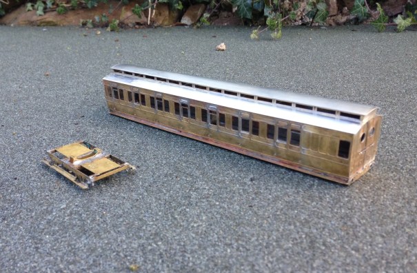
\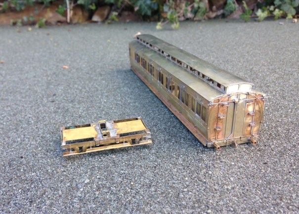
Stop by and say hello if you do visit.

Slip Ups – There is an Easier Way……………
My last post recounted the difficulties that I was encountering correctly wiring up a slip and the technique I had arrived at to overcome this, This precipitated various bits of advice including an alternative approach provided by Richard.
Richard’s solution is certainly a little easier than my approach to wire and does not need an additional point motor to run the extra switching required. It is, however, slightly less idiotproof in use than my version – this is because once the approach turnout is set for the branch in my version, the whole of the run was also set electrically. On Richard’s version, it is also necessary to decide whether the main line to yard is to be set for the yard.
This is what it looks like as a wiring diagram and it is important to note that the approach turnout (A) is also operating one of the slip’s switches too.
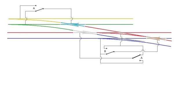
I need to fire up the soldering iron now and undertake the correction, so that we can play with trains!

A Bit of a Slip Up…….
I have been continuing with the wiring of Glenmutchkin, but have hit a snag; one that I should have been ready for – the wiring of the slip, I had been aware that a diamond crossing was a challenge to wire and I was suckered into thinking that the switches on a slip could over come the challenge, Well I go that wrong…….!!
The basic problem is that there are a choice of two routes through a diamond crossing and each route requires the polarity of the crossings to be different. The diagram below, which shows how a diamond crossing needs to be wired, should illustrate the problem. The only solution to this is to power the crossing polarity by way of an approach turnout – if you really don’t have one to set the polarity with, then you are going to have to resort to some switches – but at least it will give you a good excuse to interlock the diamond crossing with some signals to remind you on which direction it is set!
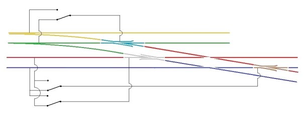
Hopefully this is clear that the crossings on the diamond crossing are activated by detecting the direction of the switch on the approach turnout. If it is set for straight ahead, then a train can’t travel over the crossing and therefore the parallel line can so the polarity of the crossings are set accordingly. Conversely, when the approach turnout is set to the branch, the line across the diamond can be used and the polarity is set to suit.
The principal with the diamond crossing needs to be heeded when the crossing is replaced with a single slip as I have, but it does get more complicated because the switch of the slip can also lead to a different route through the crossings. The crossing to the left of the slip is the more straight forward as it is only activated by the approach turnout. However the right hand crossing is more complicated as if the approach turnout is set for the branch then it always needs to be in the red polarity whereas if the approach turnout is set for the main, then it then needs to be controlled by the slips switch.
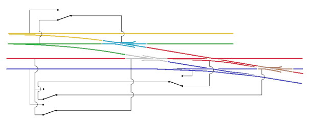
Hopefully the diagram above shows how this works.
The irritation I have, in addition to having wired it up wrong already (!) is that the approach turnout is on a different board to the slip. To reduce the number of wires crossing the boards, I have decided to simply use a duplicate point motor for the approach turnout located on the same board as the slip. It is expensive but rather more simple than the additional wires.
NB – please see also a follow up post on this wiring arrangement for an alternative approach.

Togs, Trains and Slartibartfast’s Award
The interruption in fresh posts has been caused, in part, by a recent trip to Norway – a country with some particularly fine railways (why else would we go there – well actually there are a fairly good number of reasons!).
The trains (or Togs in Norwegian) start almost immediately – this is the rather brutal looking “airport express” – or flytoget in Norway.

But the real trains are reserved for the Norwegian Intercity trains – this is the train engine for the Bergen Express:

And the suburban stock looks like this (at Bergen – top and Voss – bottom)


The Bergen line was the first of the highlights of the trips; the line initially skirts Oslo Fjords (lots of tunnels and no views) before winding through some very pretty farmland interspersed with lakes,

As the line gets higher the landscape gets starts to get harsher and the gradient steepens (you can see it climbing up the mountain in the background in this view):

By the time it gets near the top, the bulk of the line plunges into snow shelters – some 30 miles of them and there is even a station within one at the top.


If the snow sheds weren’t a sufficient clue that they have a touch of bother with snow up on the line, the collection of (preserved in this case) snow blowers left you in no doubt:

The other railway highlight of the trip was the Flam line which is a truly stupendous (if amazingly tourist) line. It rises no less than 2,831ft in only 12.6 miles – it has a maximum gradient of 1:18 which is an appreciable gradient on foot, let alone a natural adhesion railway! To deal with this level of gradient and fairly long trains, each train is top and tailed by a pair of locos, as can be seen.

The extent of the gradient can be seen in this (slightly murky) view, the line right at the top is the line leaving the junction with the Bergen line at Myrdal, it can be seen in a snowshed in the middle and we are in a further snow shed only a short way further down the line.

The line goes right down to sea level the surrounding land ceases to be quite so harsh and there is even a deep sea berth at the end of the sea fjord – convenient for cruise liners (of which Norway has rather more than its fair share!).


The rather beefy electric locomotives (class E.18 I think) have a very modern feel to them but I rather preferred their predecessors the E.17 class as they felt so much more “continental”:

Whilst that finished the railways for the trip, mention of Slartibartfast’s prize winning designs really does need mentioning. For those of you who don’t know what I am going on about, Slartibartfast was a figment of Douglas Adams’ imagination. Douglas Adams is the creator of The Hitchhikers Guide to the Galaxy and he was a Magrathean – a designer of planets. His prize winning designs were the fjords of Norway – he was so well regarded he was going to be allowed to do the whole of Africa when earth MkII is recreated once it has been destroyed to make a bypass.
So here are a few fjord pictures just to go ohh and aghh to:


It is fair to say, you can get a bit fjorded out as fabulous views are not really good enough when there are so many really fabulous and really really fabulous views out there! I think old Slarti deserved his award, don’t you?


EXPO-EM (Beer, Trains & Curry)
Whilst it is fair to say that one of the highlights of the weekend that OTCM have not mentioned – Oly’s ashen face on Sunday and his continuing insistence that he is never drinking again – here is a quick report on the trip to Expo EM.
The Model Railways of Oly Turner and Chris Matthews
It’s the morning after a show and people with any sense usually take the Monday off, not at OTCM, straight back to work. We are dedicated like that. As usual we were Portchullin Roadies, with the same mix of trains, beer and curry. It also had it’s usual pitfalls, mainly Marks ropey driving, dodgy wiring and last minute fixes.
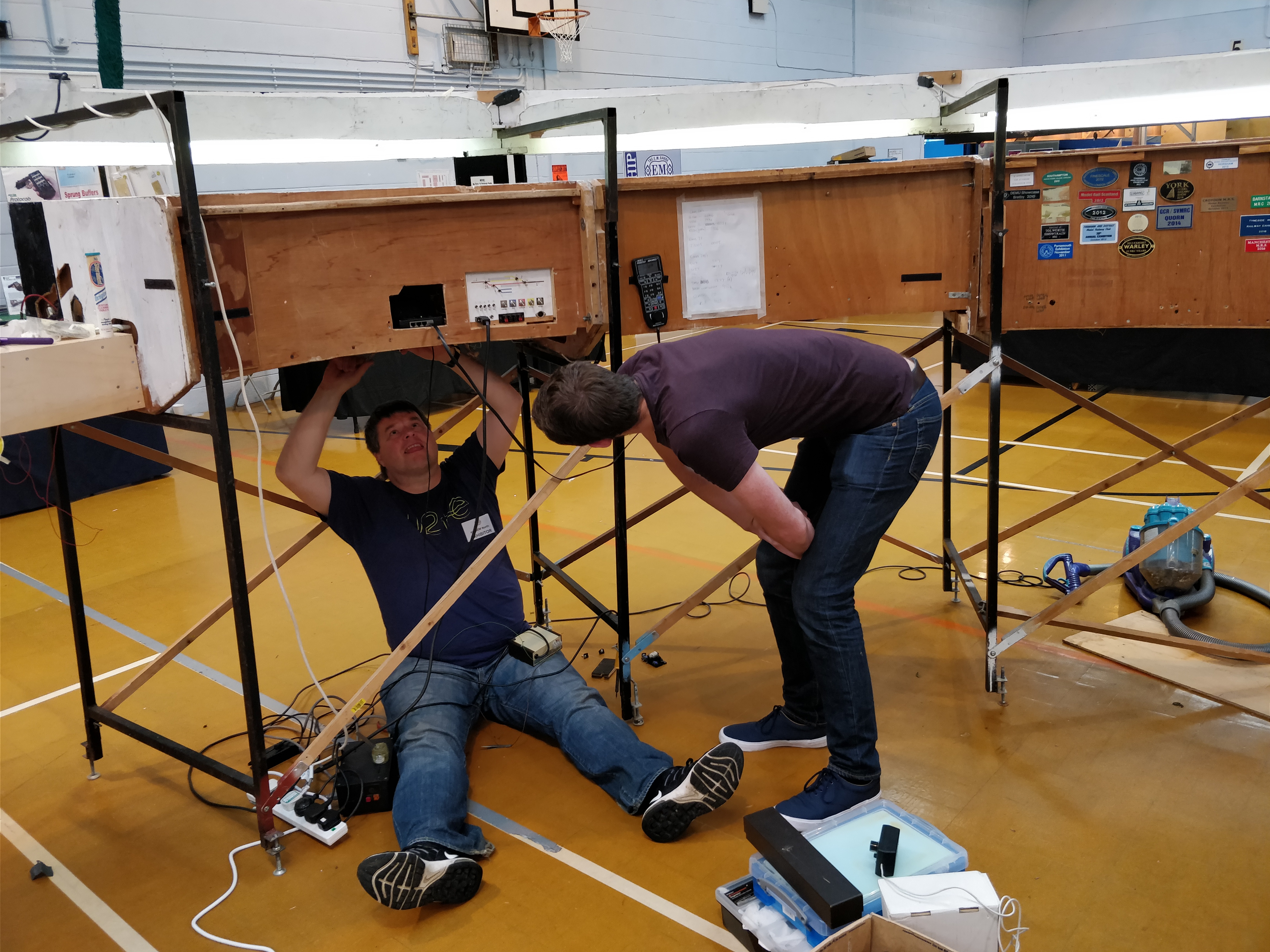 With nothing working and her legs exposed and with opening 3 minutes away, Portchullin is being her typical self
 Parking by Mark Tatlow
 A Northern trade mark, rain and sun.
But it was all because deep in a dodgy council estate was Parlington liesure centre and EXPO-EM. Under the yellowy light and the sound of lashing rain (rain like only the north can do) was a selection of good layouts and great people.
First up is some photos of Andy Clayton’s mega lush Scottish stock for his forthcoming Queen Street posed…
View original post 129 more words

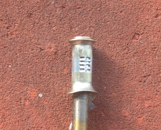
Making Louvered Chimneys
One of the most characteristic features of the Highland Railway’s locomotives for many years was the louvered chimney. This was fitted to almost all of David Jones’ locomotives and although some lost them over their lives, most retained them until withdrawal. Indeed this style of chimney can still be seen on the preserved Jones Goods which is presently in the Riverside Museum of Transport in Glasgow.
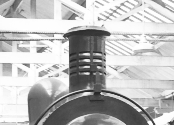
There is debate as to the reason that these chimneys were fitted but it is generally considered that they sought to assist in the drafting of the fire on the downhill sections of the line. There were many long descents on the line and regulator would be closed for such descents and thus the fire was not drafted by the exhaust from the cylinders. The louvres would have allowed the passing air to pull on the fire to keep .
Clearly for such a characteristic feature of the line, it is important to model it well on my locos but I am not totally happy with the renditions that are available. The whitemetal chimneys look too chunky and neither the cast brass (Lochgorm) or turned brass (Jidenco/Falcon Brass) have very distinct louvres. I feel that they can be improved and this is how I go about doing so; in this case starting with the Lochgorm Models cast brass chimney. Similarly, if you are turning your own chimney, the same situation arises,
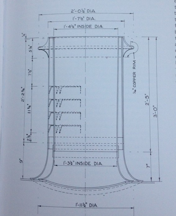
I started by some basic improvements to the chimney. I found that my casting was not parallel down the shaft of the chimney, being fatter at the top, and also not particularly smooth. I therefore turned it down a little on a drill with some needle files. The casting sprue was not particularly central so to be able to turn the chimney it was first necessary to file this to get it more central. Thereafter, I drilled out the chimney to 4.5mm diameter to its full depth on a pillar drill. I am doing this partly for appearance but really because I intend to put sound speakers in the smokebox and it is necessary to leave routes for the sound to escape – the most authentic being to chimney! Casting brass is very hard and this is no little task – it takes some time, lubricant and anyone in the house need to be able to tolerate a good amount of noise!
The Lochgorm Models cast chimney has a series of depressions to represent the louvres and these are what I felt needed improving. I started this with a piercing saw with a fine (OOOO) slot at the top of the cast depressions. This is cut across the whole width of the depressions and a little further beyond, ignoring where the pillars between the slots are.
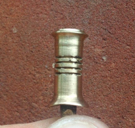
These are then given a chamfer slope with a needle file that has a blank face (to make sure it does not cut above the slot). This also needs to be taken beyond either end of the intended louvres to avoid the impact of any taper. The top three have been formed in the picture below, with the lowest still just the piercing saw cut.
Once all have been formed, the next task is to undo all of the work by filling them in again! All of the gaps are flooded with solder. I used 145 solder as it would survive the reasonable temperatures that would be incurred in soldering it to the boiler but also be soft enough to carve out again.
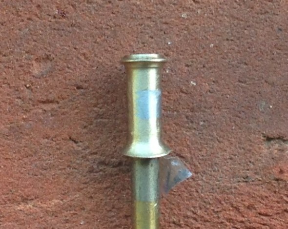
The louvres were then marked out, starting with the two vertical rows either side of the central pillar that must match the highest point of the flare. Then with a knife, the solder infill between these is cut back out. The knife can cut through the solder to cut it out but does it will not affect the brass, so the louvre is reformed. I found that the technique was to initially cut it away and once a basic amount was removed the blade can be scraped side to side within the louvre to get a smooth surface. This brings up burrs of solder at either side of the louvre which are then cut out. This is what it looks like with the first two columns of louvres done – I found it best to do it like this as it was easier to get them vertical than by doing them in rows.
You will find that you get through a fair few blades doing this as the most challenging part is getting the corners crisp (and the photography is very cruel in this regard!). It is also easy to be a bit enthusiastic and accidentally cut pillar – if this happens, it can be reformed with a dab of solder and the process repeated until there is a neat row of four slots in four columns.
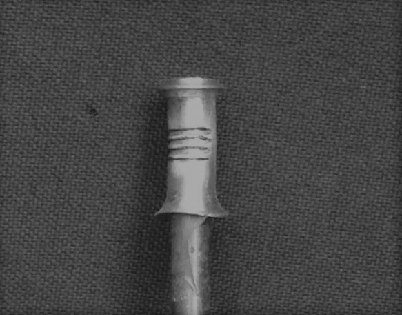
Once you are near to finished, a dusting of grey primer shows up any remaining inconsistencies and hopefully it looks something like this:.
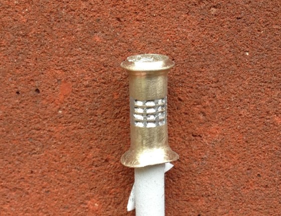
This process creates not only the slope of the louvre opening but also the dark shadow of the cavity. In my view these features are necessary to capture the feel of the distinctive feature of the Highland Railway. It takes around 2-3 hours to make each chimney and in I reckon it is worth the time and effort.

Princes Risborough North Box
As part of the Missenden Railway Modellers summer retreat, I was lucky enough to be invited to see the Princes Risborough North Box, which is now in the custody of the Chinnor and Princes Risborough Railway Association.
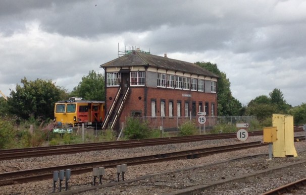
The box had lain derelict for many years, since its closure in 1991. Somewhat peculiarly, it was a break in by vandals during this period that potentially saved the box as it identified how seriously affected by water penetration and rot it was. This lead to the preservation society being able to convince Network Rail to let them in to stabilise it and they feel that had this not have occurred, when the building’s distress subsequently became apparent to Network Rail they would have merely ripped it down.
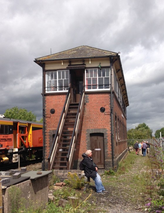
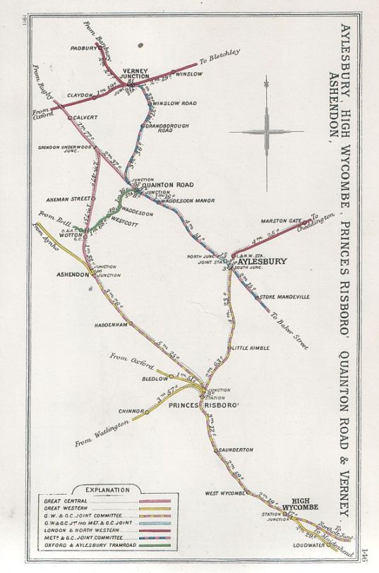
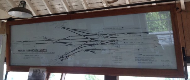
The box is substantial and is apparently the largest remaining GWR signal box in the country. It originally controlled the north end of Princes Risborough station but its size was determined by the complicated junction at this end of the station with three branch lines splitting from the main-line to Bicester and beyond. The branches it served were Aylesbury (still part of the national network), Oxford (closed in 1963) and Watlington (closed in 1957 but now reopened to Chinner as part of the preserved railway). The Railway Clearing House map is below and just to prove the complexity the box diagram too!
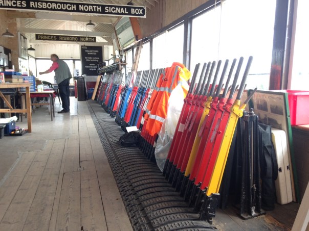
As would be imagined, there is a fairly extensive array of levers although in the various rationalisations that occurred through the GWR and BR eras have reduced the extent of these significantly. The preservation association have, however, reinstated many of the missing levers even though they are not yet connected to anything.
At present, the preservation society only have a temporary connection into the Princes Risborough bay platform but the intention will be to make this a permanent link onto their line, signalled via the box. However, given that this will still only be one of the lines that the box formerly served, there will only be a limited amount of it in use. Apparently the plan therefore will be to separate off the bulk of the box to create an interactive museum where visitors can play the part of a signalman.

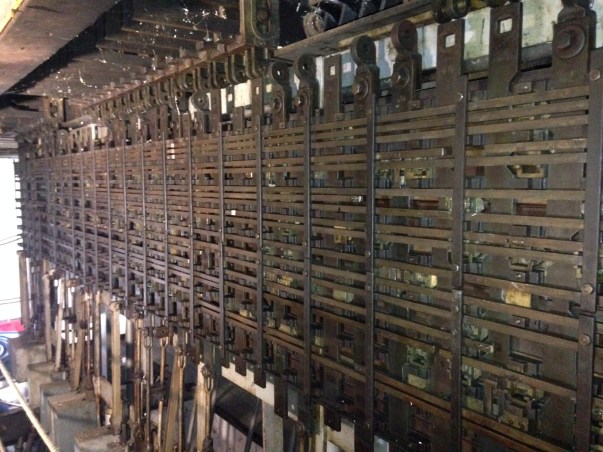
The treat for me (and many of the others on the visit) was to go into the frame room to take a look at the locking frame. Although I had seen this in model form before, I had never seen a full sized locking frame – even though this is only a shadow of its former self as it only covers that proportion of the box that was in use at 1991, it is still very complicated as you can see.
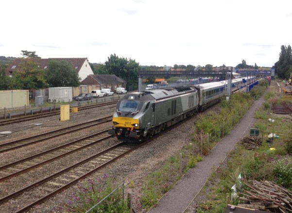
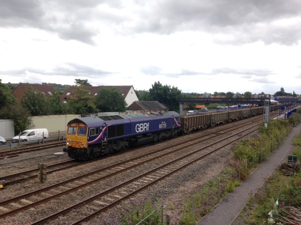
The Chiltern line is now really quite busy, far more so than when I used it to get to Solihull on business regularly. In addition to the procession of class 168 DMUs, there were class 68s on the trains for Birmingham and Wrexham plus a pair of trips each day with class 66s on spoil trains from the Thames Tideway sewer project.

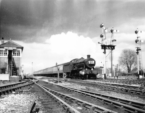
And finally, this is what the box looked like in the days of steam. This photograph was taken in 1960 by Christopher Bomken when he was still in his shorts – it even won him 2 shillings and sixpence in a school photographic competition. Recognition at last Christopher it has made the interweb!

Dia 51 Test Build – Part 2: Nearly There
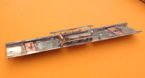
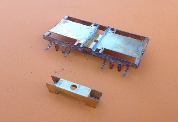
I no longer affix roofs firmly to the body of my coaches as makes both the building and the painting much easier. The downside of this is that there is the challenge of keeping the roof on tight without there being any visible joint between the two as this looks terrible. The solution I now use is to clamp this to the floor with 10BA bolts by way of brackets as can be seen in the photograph below.
As built, these coaches had full length step boards but they lost most of these through their life. They were electric fitted from the outset. The chassis below is close to finished except I have run out of vacuum cylinders so these will need to be added, along with the vacuum pipes.
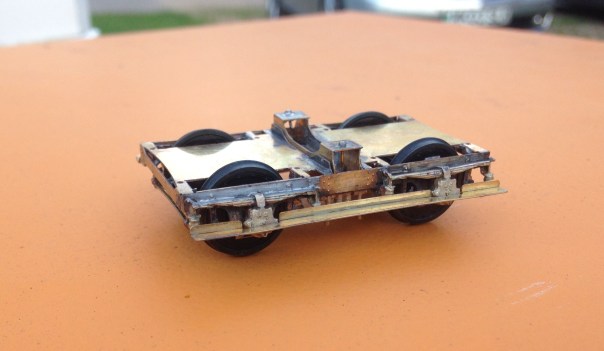
The bogies are also a key part of the proposed kit and are something that I have been working on with Justin Newitt of Rumney Models – the idea being to combine the sprung bogie design that he has prepared with cosmetic etches for the sides and then the castings from Lochgorm Models or perhaps our own in due course. The bogie is quite sophisticated with both primary and secondary springing – the latter is on the bolster and is as below.
The primary springing is on the axleboxes and has bearing carriers, much like the Bill Bedford sprung W-irons. There are still some wrinkles to iron out so it is not there yet but they do make up into some pretty neat bogies; don’t you think?
The only area of the first test build that truly did not work was the corridor connections and it is going to be a case of back to the drawing board for these but other than the final few bits to be completed, the build is finished and I think the vehicle is handsome.
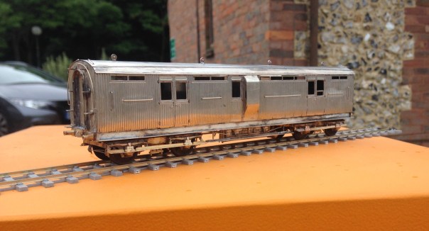
So, off to the paint shops soon, but there is a bit of a holiday to squeeze in first!

Dirty Models……..
Now, I wonder if that heading will gather a few extra viewings………..?
As I have mentioned before on this blog, every few months I catch up with a group of mates to have a joint modelling session. The general gist of these is a combination of banter, a bit of modelling, more banter, a visit to the pub, even banter, a bit more modelling and all nicely rounded off with some more banter.
Last week saw us on the south coast to do some weathering – or rather some of us. One of our number was preparing for their imminent marriage whereas Oly (one half of OTCM) felt his budding TV stardoom was a sufficient excuse to hang up his airbrush. We do fear that Oly may not return to the fold; preferring instead to do his modelling with Brad, Leonardo and Denzil once he makes his silver screen debut in the autumn – don’t forget your roots Oly……….
We were all concentrating on different things; Peter constructed the better part of a bridge for his Aultbea layout and Chris was weathering some rather neat little shunters. For my part, I concentrated on weathering some of the stock that I have been building lately (and sometimes not so lately!):
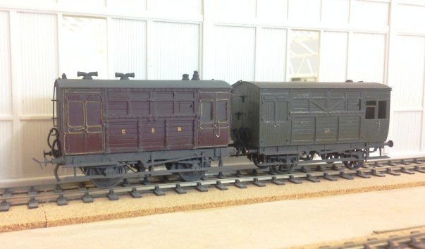
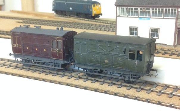
First up is a pair of horseboxes. On the right is my HR version based on a Microrail kit – still in need of some glazing. On the left is the Caledonian’s equivalent based on a kit from by Spratt & Winkle. Both are in their pre-group livery as can be seen. As such stock was used in passenger trains, I have sought to give them an aged but largely cleaned feel – with the dirt largely present around ironwork and difficult to clean spots.
Having mucked up the weathering of some brake vans at the previous weathering session, I was also keen to get these corrected. This is where I have got with them.
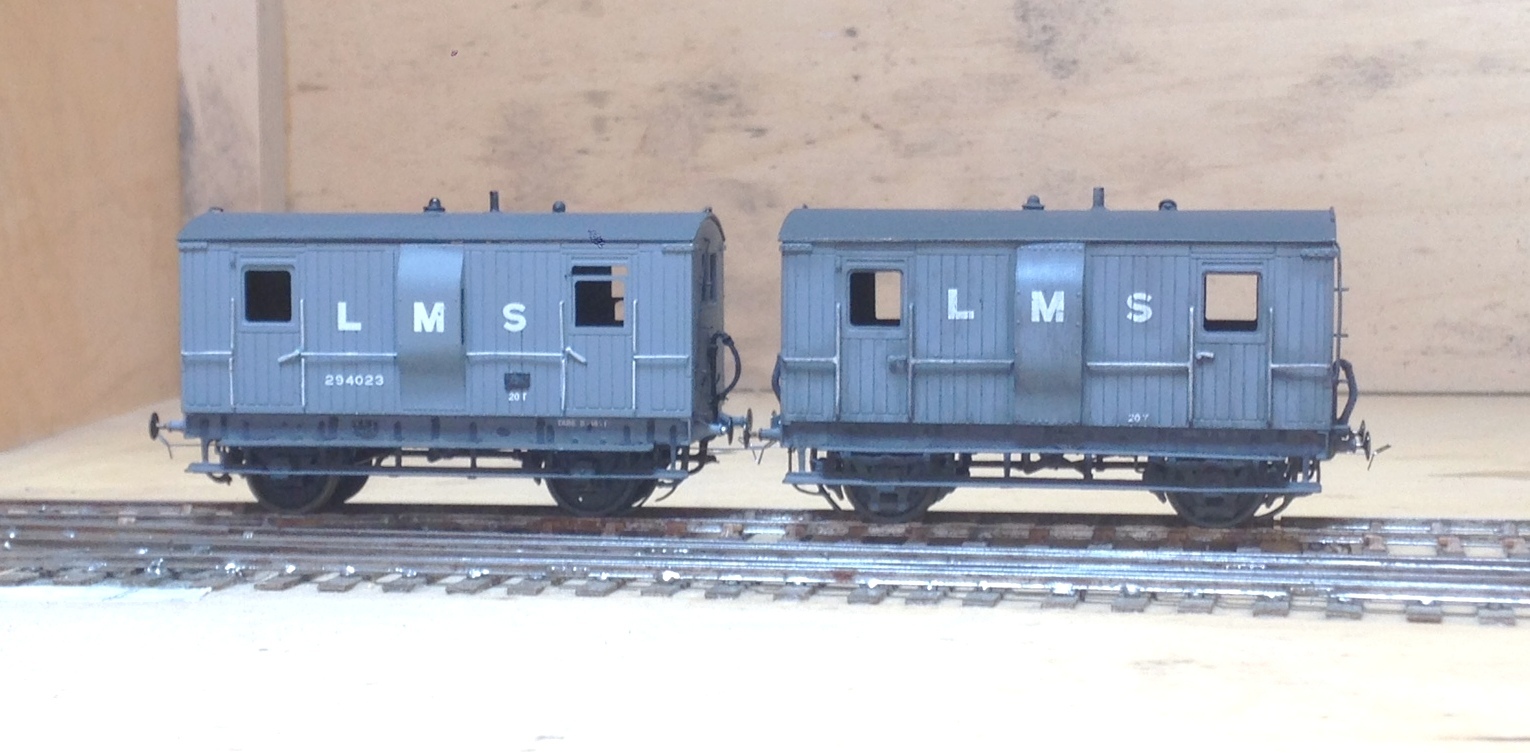
As can be seen, I do not follow the school of thought that the pre-group or 1920’s era stock was constantly pristine. If you bother to look at contemporary photographs, little is clean and some of it is downright grubby. Railways in the steam era were very dirty places; it is inevitable where so much coal, ash and smoke prevail. Furthermore, I can not see even the most houseproud of railway companies regularly (or probably ever) cleaning their goods stock and most of these show stock that is care worn and soiled. This is the feel I am seeking to capture; not the utterly neglected and on its last legs look of the final days of steam but of railway materials that earn a living the hard way.
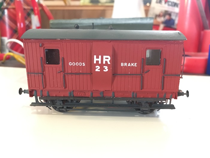
The pair of brake vans above are to HR diagram 39 from 1922 and are from a Lochgorm Models kit. There is some doubt whether they were delivered in 1922, as there are no known pictures of any of them in HR livery. However, I applying the “its my trainset rule” a number of modellers have painted them in Highland colours; including Paul Bannerman whose example is below.
The other highland brake van I weathered was the diagram 38 brake van. This originates from a Microrail kit and may well still be available from David Geen occasionally at shows as he does own the rights to the artwork. I have modified this with the early pattern roof look outs. These allowed the guard to look over the train around the twisting curves that characterised parts of the Highland’s system. However, there were complaints about whacked heads as the guards came up and down the steps to look onto the lookouts and as a result they were modified with approach cutouts on the roof – take a look at the Lochgorm’s page above to see an example.
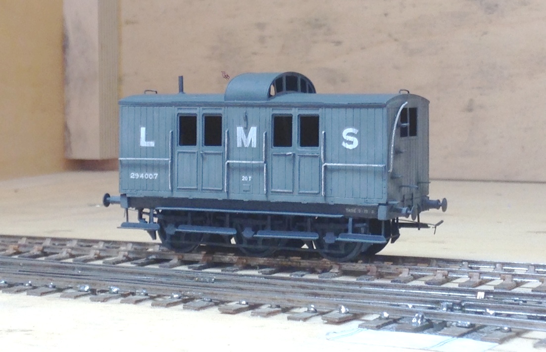
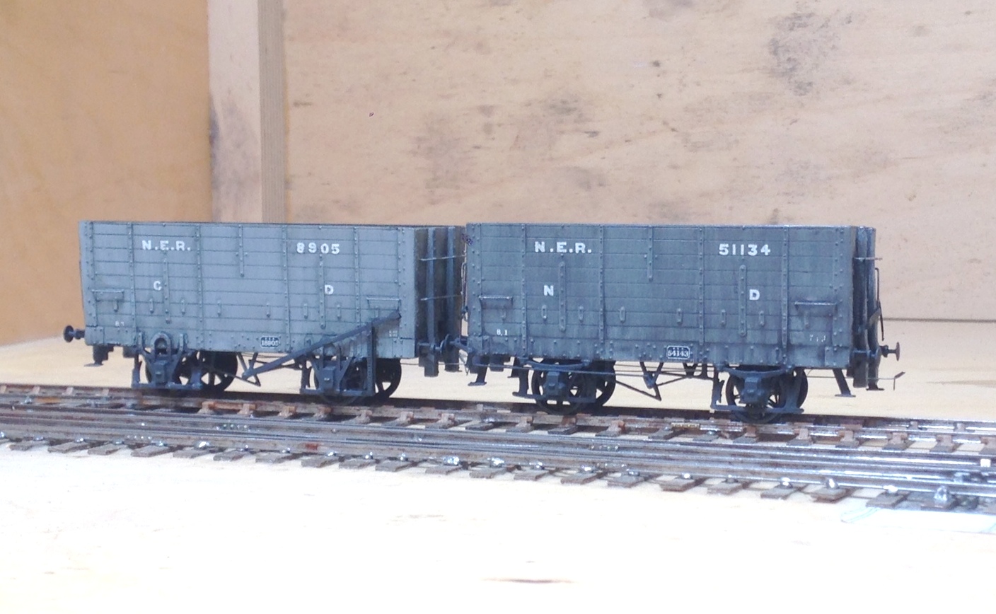
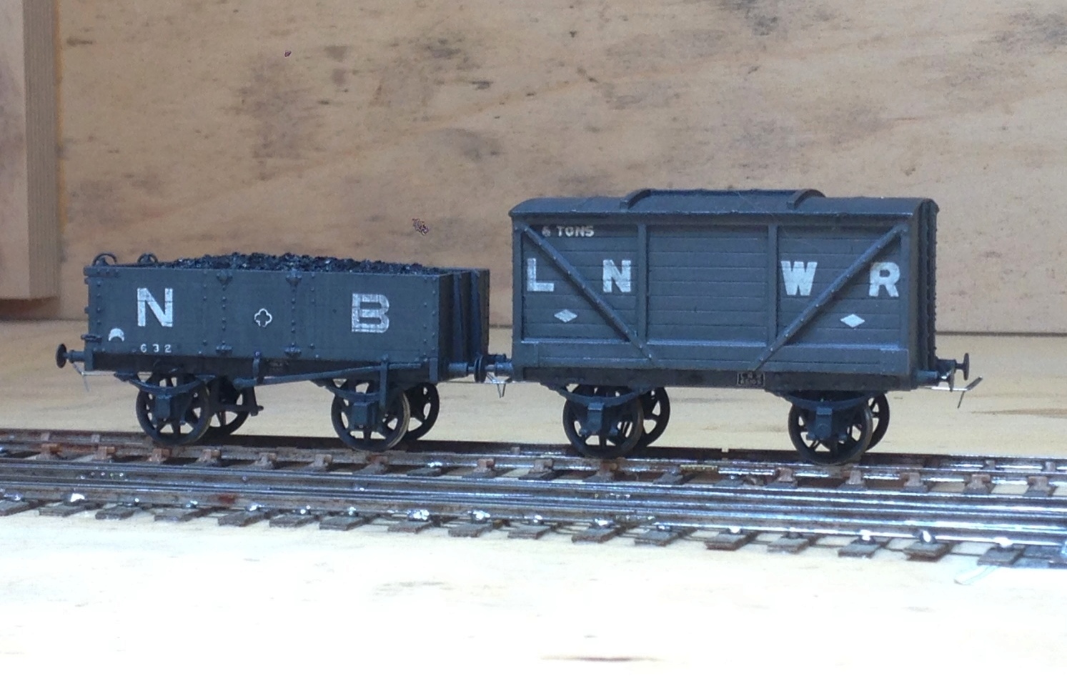
Next up on the weathering front were some wagons and NPCS. The first pictures being the weathering to a couple of the items I have described in the pages here – the Oxford Rail NB jubilee wagon and the Mousa Models LNWR van.
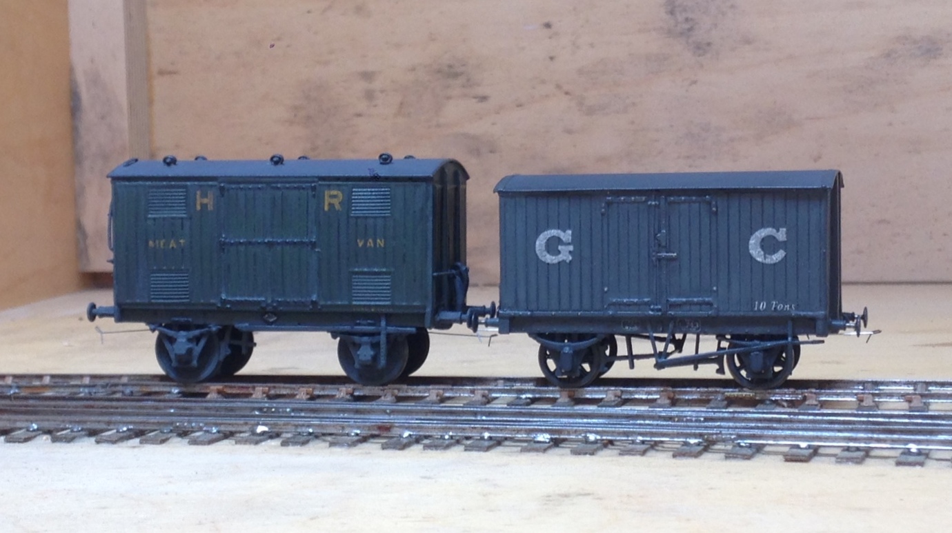
And then some rather more ancient models of mine, a Highland Railway meat van from a Sutherland Castings kit and a GC van from another Mousa Models kit.
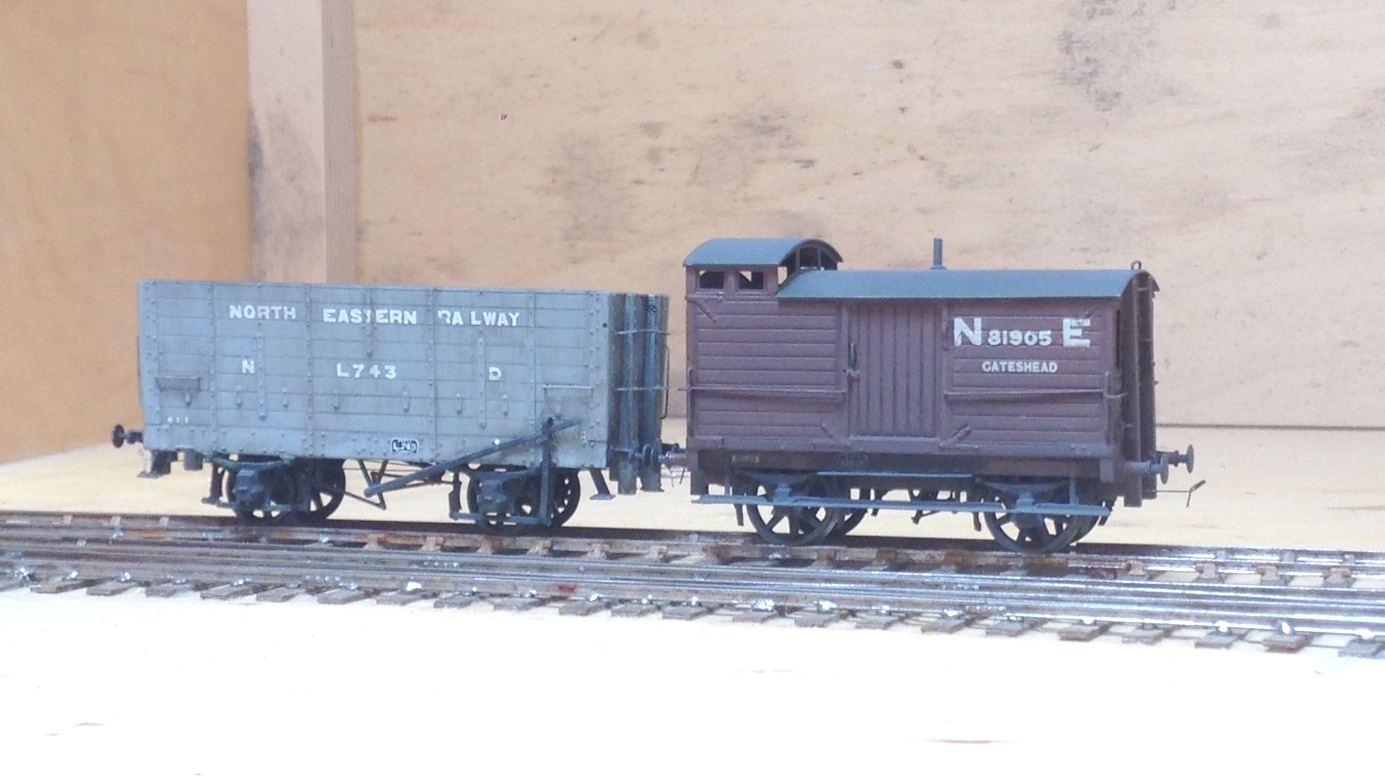
Finally, a group of wagons for Benfieldside. The hoppers have been seen before and the brake van we will hear more of another day.