Blog Archives
NER Hoppers
I am presently cracking on with a batch of NER hoppers for Benfieldside. Having acquired the layout, Tim and Julian have very little stock to run on it, so as part of the repayment for the use of their facilities and expertese on my boards, I thought I would help to correct this shortfall.
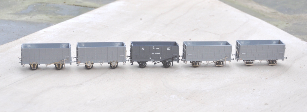
The origins of all of this present batch of hoppers all go back to the Slaters’ injection moulded kit, which is of diagram P7 wagon. There were around 17,500 of these wagons at the time of the grouping and the LNER carried on building them for some years thereafter with only subtle differences; so not unsurprisingly there were quite a lot of variants. Thus, I have been doing a lot of modifying!
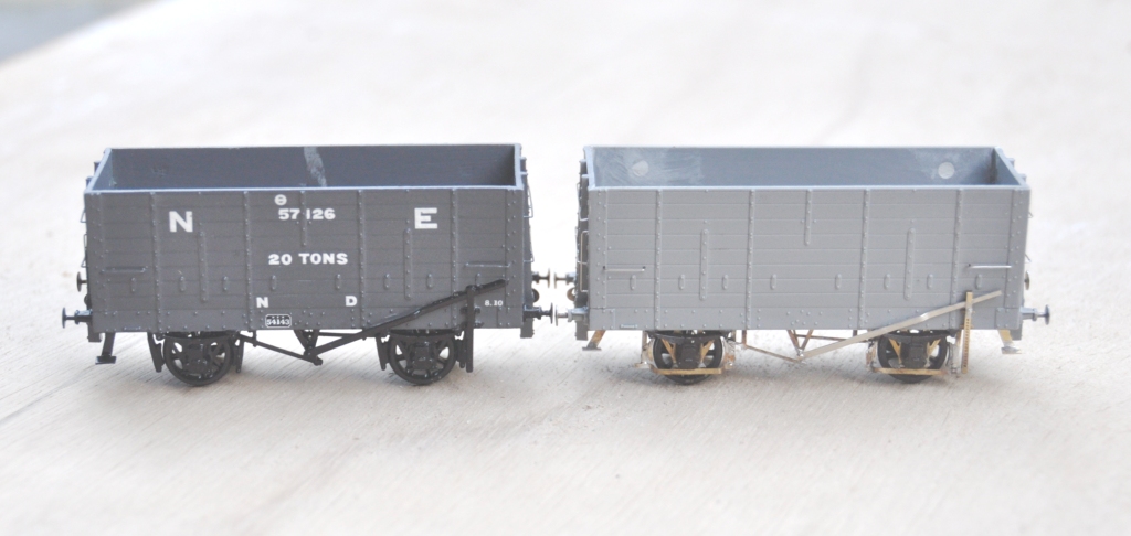
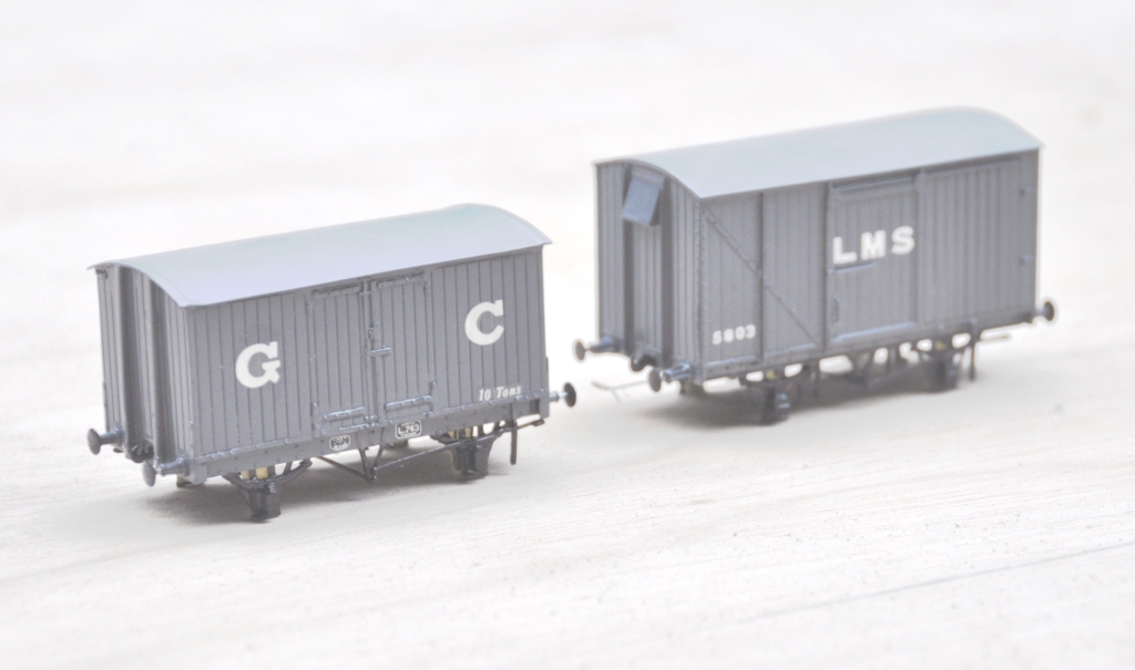
In each case, I replaced the very clunky W irons with Bill Bedford replacements; even though these were to be to EM, I felt that they would improve their performance. The first examples were essentially built as the kit was intended with fairly traditional brake gear (which was to one side only). However, having built my first one, I decided to refine the brake gear by drawing an etch for replacement steps, V hangers, morton brake mechanisms and brake levers. This (along with a comparison with the plastic equivalent – the painted wagon), is below:
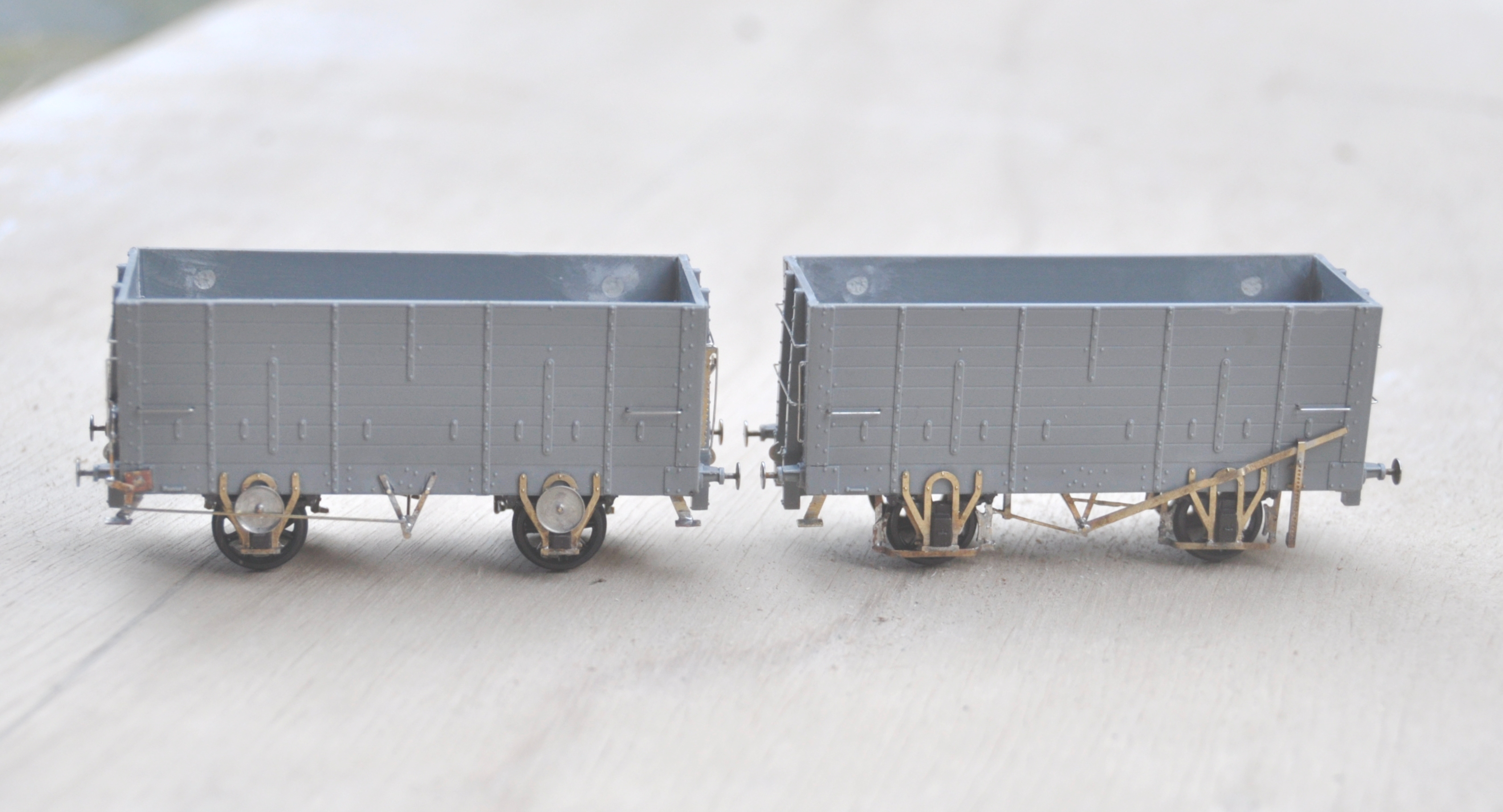
However, a significant proportion were modified with end levers that operated a crank that was connected to the Morton gear. At the ends, there was a much more chunky ratchet arrangement to retain the lever in position. Again, I drew this up on the etch, and the arrangement looks like this:
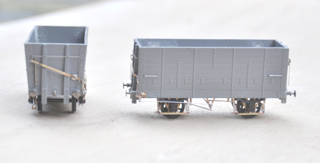
The NER undertook a number of experiments with these vehicles to attempt to reduce rolling resistance and this was the subject of my next modification. On the right (below), shows the provision of a second outside set of W irons. This was to add stiffening to the axles. There is a set of Bill Bedford W irons to cater for this, but I chose instead to create a fresh set on the etch. On the left is a further variant, where an anti-friction bearing was added in addition to the outer W irons. This was a wheel that ran on the top of the axle and I presume the idea was that as it rotated less, there would be less friction. I suspect that the introduction of an open bearing surface that would instantly get contaminated with coal and grot would actually have the exact opposite impact – as these were removed by the grouping era, I may well be right!
The final variation of construction that I have modelled was a slot cut into the ends, which appeared on some vehicles. The NER used these on vehicles that were hauled up rope inclines – of which they had many. A plank of wood was inserted into the hole and wedged such that it was secured behind the end posts to ensure that the haulage point was close to the centre of the wagon. They found without this that there was a tendency to pull the end posts loose due to the uneven point of pressure.
Next up will be the painting and lettering of these; where I have three eras to chose from that would have all been apparent immediately pre- first war, which is when Benfieldside will be set. More on this in a future post.
If there is a desire from anybody for the etches, I would be able to offer them; so drop me a note?
HR Cradle Bolster – First Test Build
I had a delivery from PPD a week back, so I have been playing with some test builds of this:

This is a dia 25 cradle bolster; a type of vehicle that I have not seen on another railway. It has a square cradle that sits on the top of this, with four bolsters protruding from the corners of the cradle. They were used on pairs and the whole cradle rotated when the pair of vehicle went around curves. The intention, I presume, was to offer the load more support by offering more points of contact. Anyway, as no one else had tackled this vehicle before, I thought I would have a go!
As this is my first etched design for a vehicle, I have certainly encountered a number of problems. As the top photograph shows I produced this in both 4mm and 7mm; the latter has proved more successful due to the thickness of metal being greater. The main issue that I created for myself was to half etch the solebar overlays so that the rivets and the ironwork could be portrayed. However, rather than backing them on a further layer of etch (like the etched kits I have built – they evidently knew something……), I spanned it between supports. The intention had been to make the kit fold up more readily but in practise what has happened is that the half etched solebars have distorted (badly in the case of the 4mm one) due to the stresses introduced in the heat from soldering. Thus, whilst I have a working model (at least in 7mm), a rework is going to be required.

Both the 4mm and 7mm versions will have sprung axleboxes, using a varient of the guitar wire sprung version used by Bill Bedford and others. The 7mm chaps don’t seem to use it much and I guess the mass of their models helps. However, it does glide with the springing and is better as a result I reckon.
I have also done a 3-D design for the cradle, which I am proposing to use as a master for some resin castings (certainly in 7mm, I might go down the lost wax brass route in 4mm). A new process that I have not previously attempted. I need to find out where to get axleboxes and buffers from – Larrie Griffin I presume.
Also back from PPD, were some etches for something altogether more bold (which is a worry in the light of the problems I have encountered on a relatively simple wagon!). This is the chassis and body etch for a Drummond Scrap Tank. I have made a start on this and again, some reworking will be required but again there is a viable model in an amongst these parts; it just needs tweeking. More to follow once I have got further with it.


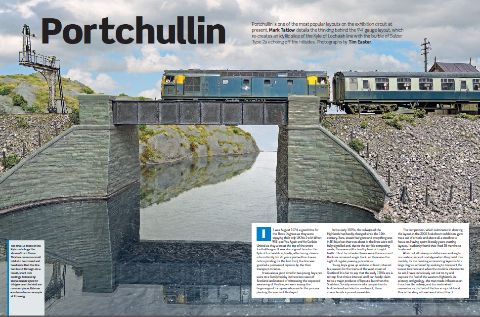
Portchullin – Recommended Reading
Portchullin is in the press!
Rail Express have for many years included a modelling section to what is otherwise a prototype magazine. This year (and going forward in future years I beleive), they are producing a yearbook which is dedicated to only modelling features. Portchullin is the leading article with a series of photos from Tim Easter – and it is no less than 13 pages long.
Here is a taster and if you want to get a copy, it can be obtained here:
Peter Bond’s Aultbea
I can’t claim any of the credit for this one, it is the work of one of my friends and stalwart operators of Portchullin, Peter Bond.
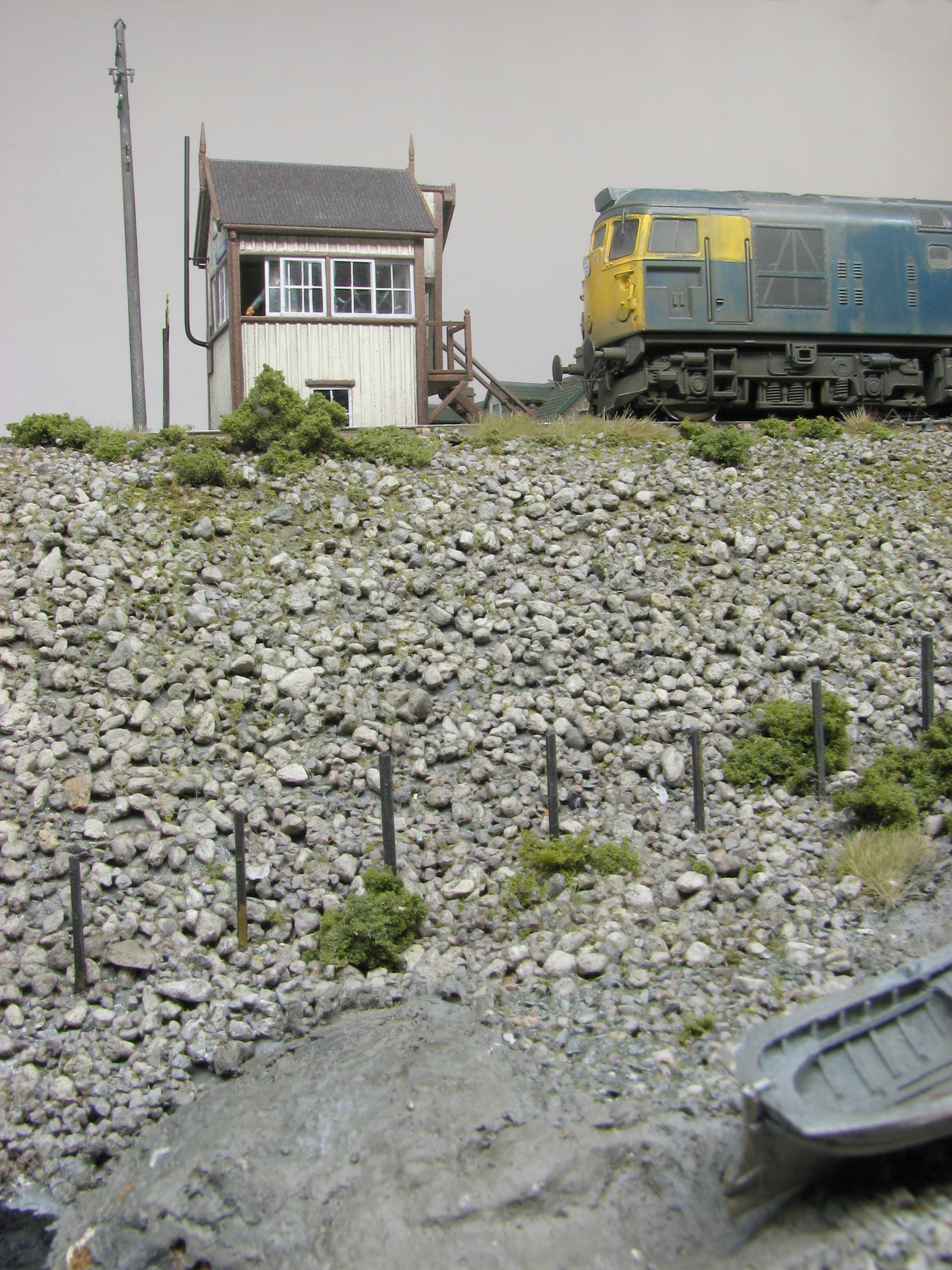
His latest layout (in EM) is based on the line that was proposed from Achnasheen to Gairloch and Aultbea. This was a real proposal in the late 19th century but the scheme came to nothing. Peter has imagined that not only was it built but it thrived; to a large degree due to the naval connection where the navy did use Gairloch as a significant port. He has also presumed that Aultbea became the port for the Hebrides and thus the Kyle line faded away (a point I don’t like!).
You can see in this view the rather nice model of the signal cabin for Aultbea, based on that at Kyle. The description of the building of this was in BRM in September and October 2012 and is worth a read.
The layout is pretty big; some 30 feet long and relatively deep at the station end. Peter envisaged that with the rise in traffic during the first war, the station had to be enlarged – much like Oban was when the Ballachulish line was built. Indeed, Peter is taking a lot of his inspiration from Oban, including portions of the trackplan, the overall roof and the engine shed being a little detached from the rest of the station. As you can see, it will be set in the late 1960’s so a little earlier than Portchullin.
Now Peter is an inveterate starter of layouts, so by posting these progress pictures, I am hoping to prod him along to finishing this one.
Over to you Pete!
First Four Boards Complete!
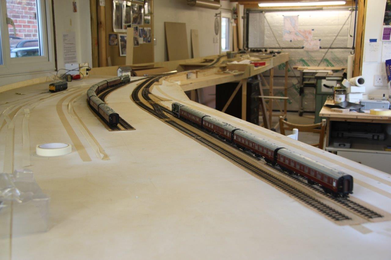
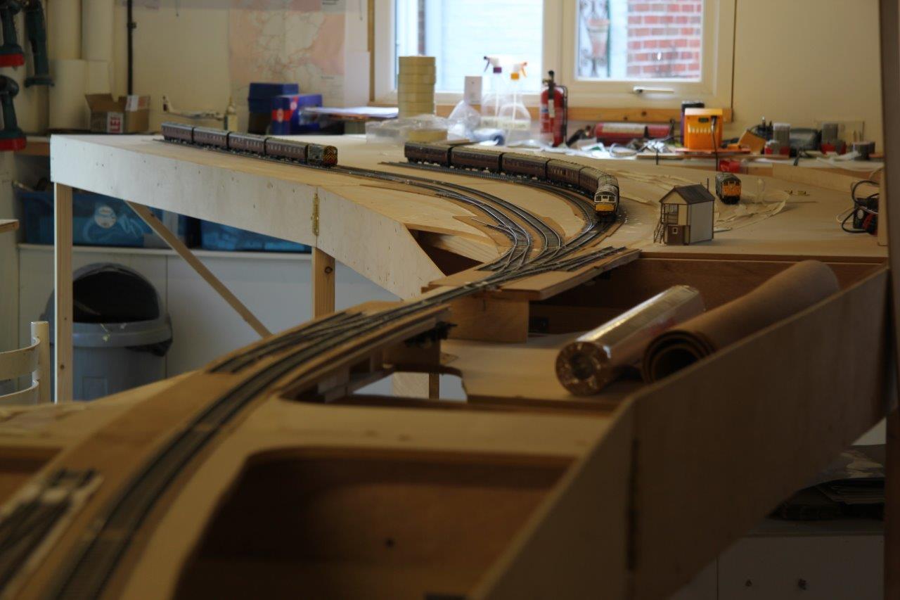
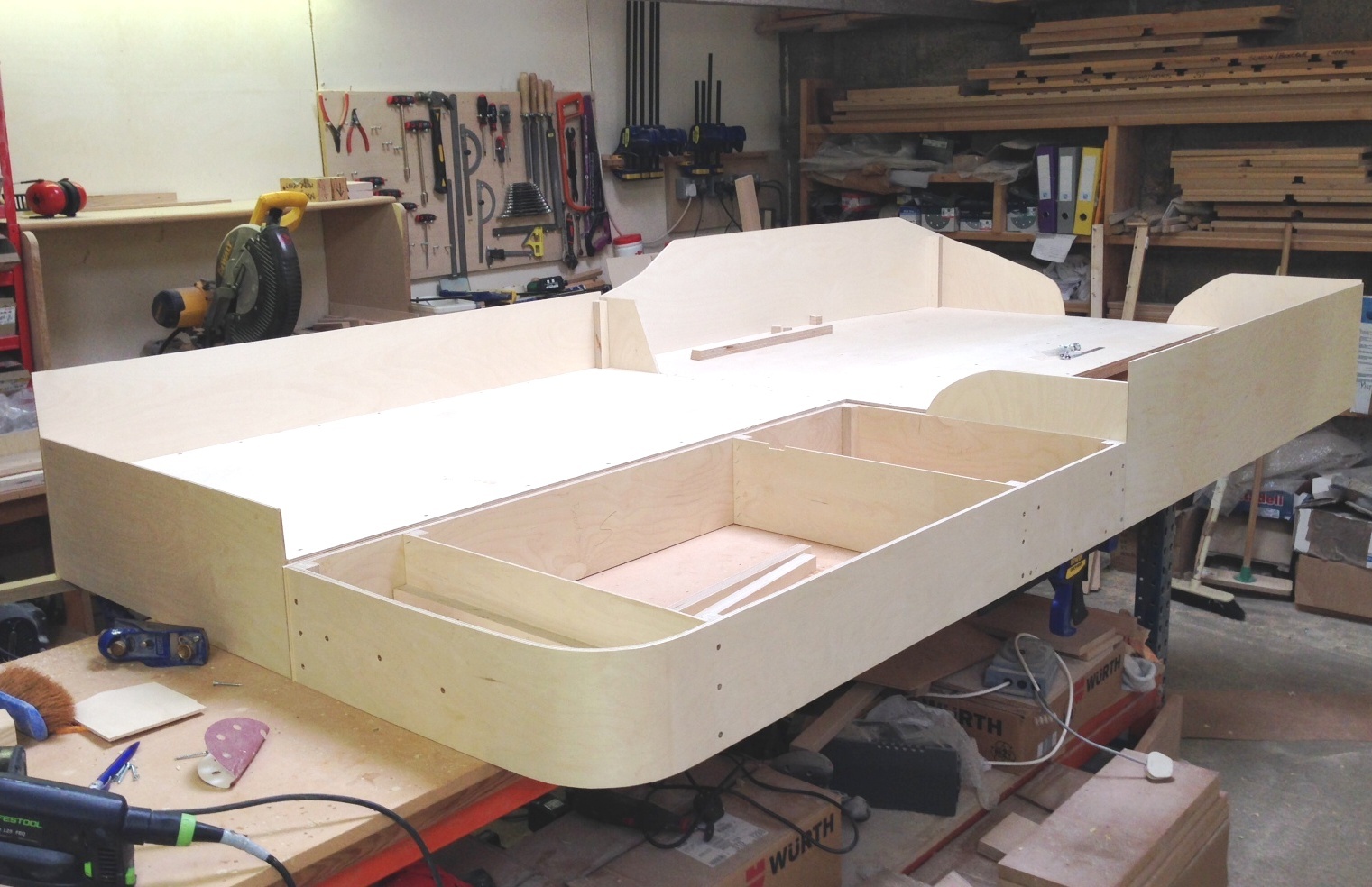
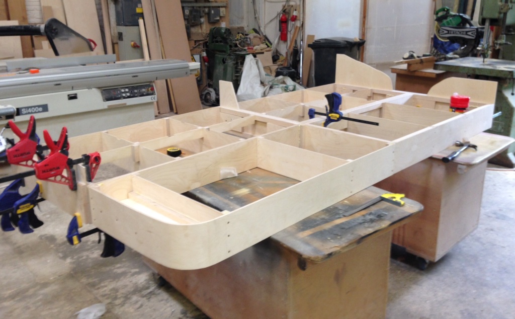
Julian and I have been putting a bit more time in on the baseboards, to the point where the first four are complete with the exception of their varnishing/painting.
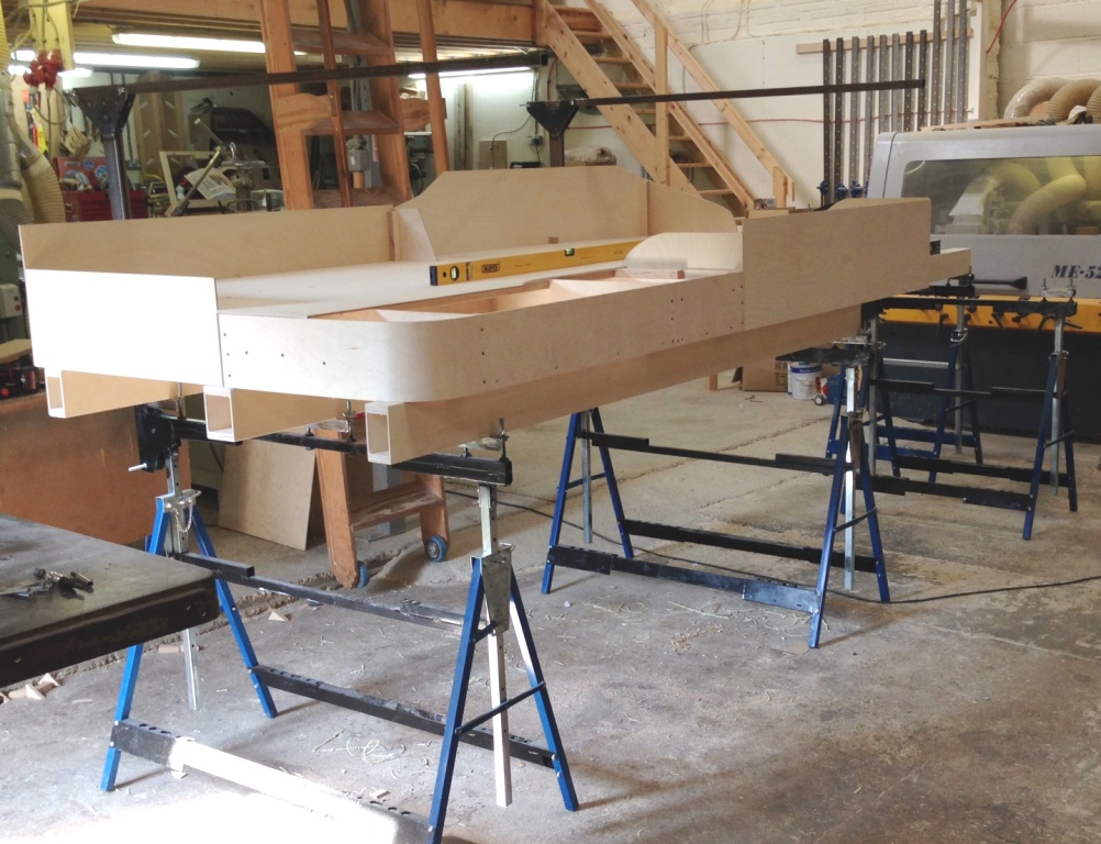
You will also see in the pictures that the beams that support the boards have also been completed. These span between the brackets that were shown here which in turn are supported by bolts that have been affixed to the builders trestles. This means that each point of contact can be adjusted for both overall level and also cant. The idea is that this is done prior to placing the boards on the beams, so that the whole thing can be levelled as one and the boards then just get plonked on. So long as the floor is not too wonky (like that in Tim & Julian’s place!), this does not take long and it is very idiot-proof assembling the layout perfectly each time.
Also visible in the views are the gallows brackets that will support the lighting and facia. These are fairly meaty as they have to span over 1300mm from front to back, so the moment on them is quite high. What we have just found is that they are a tad low due to the beans being a bit higher than I had expected. A bit of adjustment will be required in due course; especially as the layout level is also a bit high.
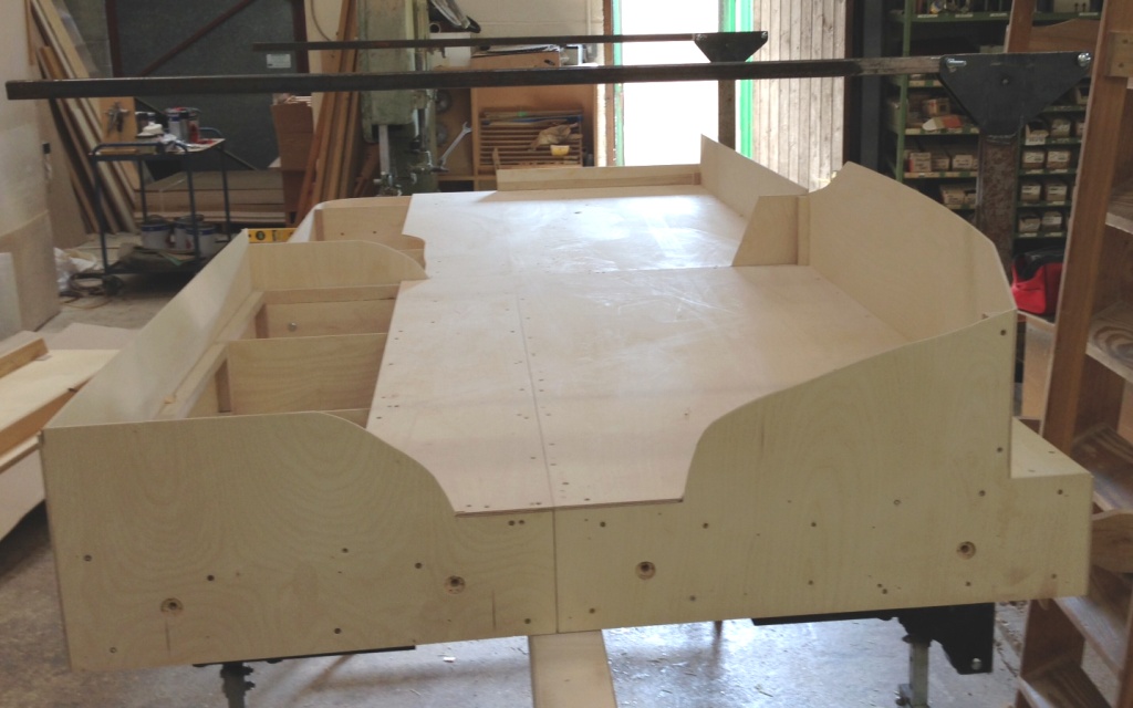
But the acid test of the new boards is shown in this view. On Portchullin one of the problems is that the boards rise up slightly at the joints – a problem I see a lot on layouts. This is dead flat; so we won’t see the trains doing any Casey Jones runs over the mountain ranges!
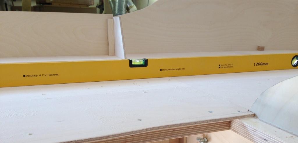
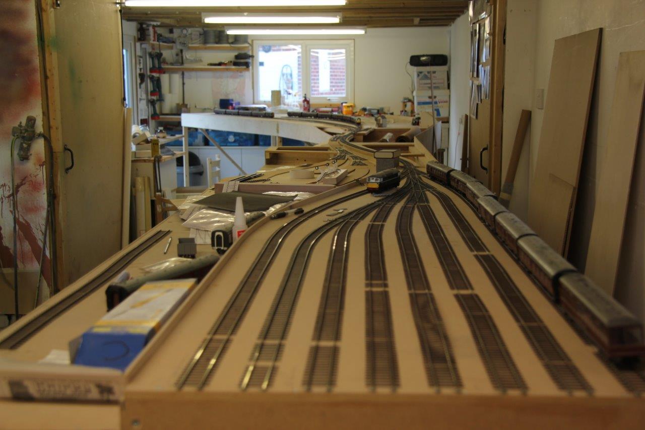
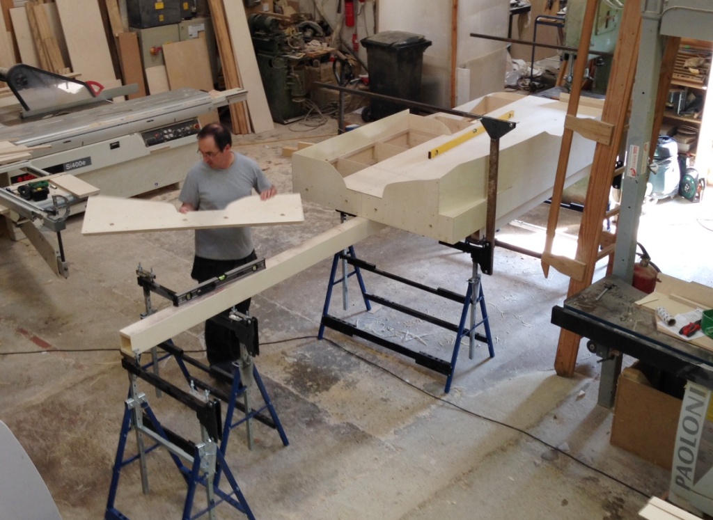
The next visit will get on with the last two boards, which will take up the rather obvious space where Julian is working. These will only be a single width in size as the boards are tapering in to 700mm wide at the end on the left in the view below. To give a sense of scale, the yellow spirit level is 1200mm and the dark one 750mm. (see Mr Ullyot – two spirit levels now………..)
So thanks again to Tim & Julian and if any of readers are looking at electric loft ladders; give them a call. S&T Joinery.
Baseboards coming along……….
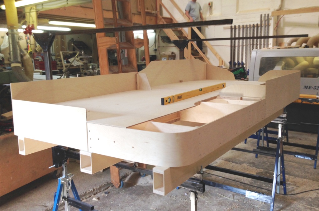
Tim and Julian’s business has been doing rather well so far this year, which has meant that they have not had time to accommodate me at their joiners shop and hence baseboard construction has been slow. However, I did manage to get down today and we have got the first four boards quite close to finished.
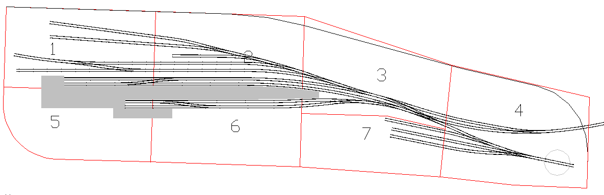
This view will look straight at the train shed, with the bay to the right (it does come onto the nearest board; this is a bit not yet done. The remainder of the platforms be to the right and the goods yard will be behind the trainshed/platforms. If you want to be reminded of the trackplan, it can be found here or here.
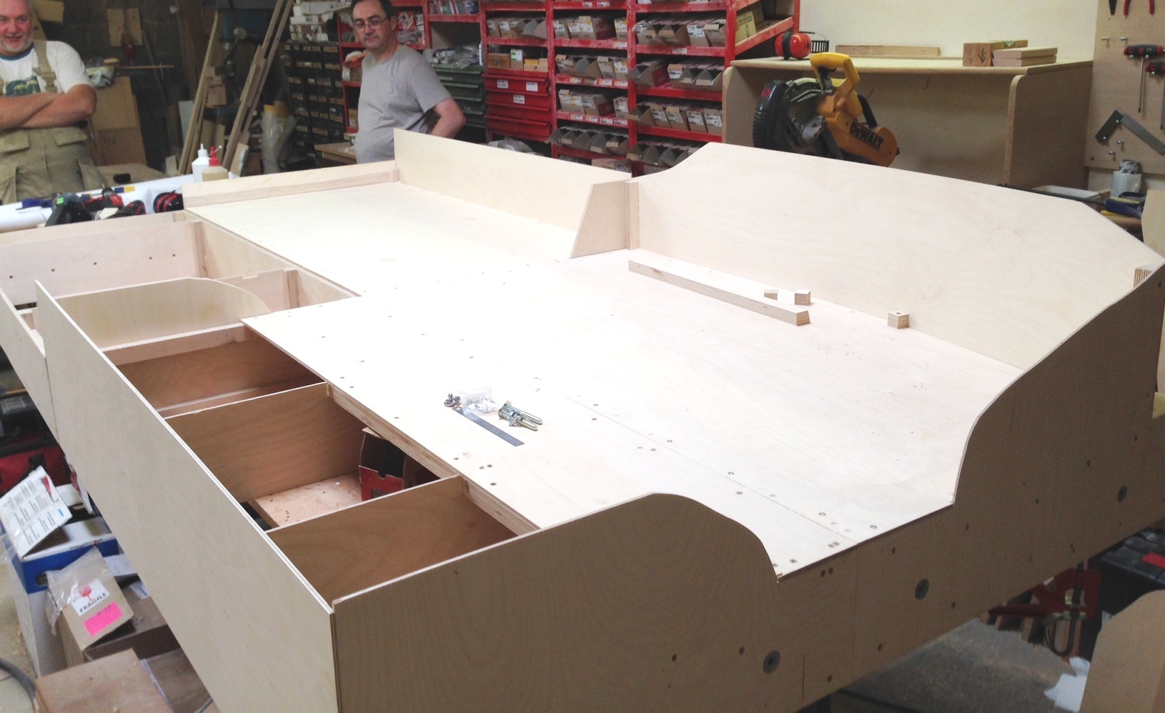
Tim and Julian look on the four boards and give them a comparison for size. The overall depth is 1200m deep and the length of the boards in visible is 2.6m. This view would be from the bridge (see the trackplan links), looking back over the yard and the end of the platforms. The ground will be raised here, but falling away to the left.
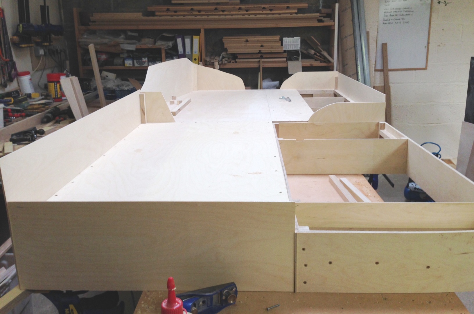
A view from the buffer stops, well it would be but you wouldn’t be able to see them for the end of the trainshed. The ground will slope down substantially to the right and be above rail level to the left.
I hope to get these four boards finished in my next visit and also the beams that they will sit on (and will be attached to the legs already made).
Portchullin at the Great Central Railway this Weekend
Portchullin’s next outing will be at the Great Central Railway‘s model event on Friday 20 June through to Sunday 22 June.
I have been looking over the stock and we should be up to around 7 trains, which is close to an all time record! Might even break out one or two unusual ones, even if they do still need some detailing work on them.
Whilst we have seen these pictures before, they are worth showing again……….

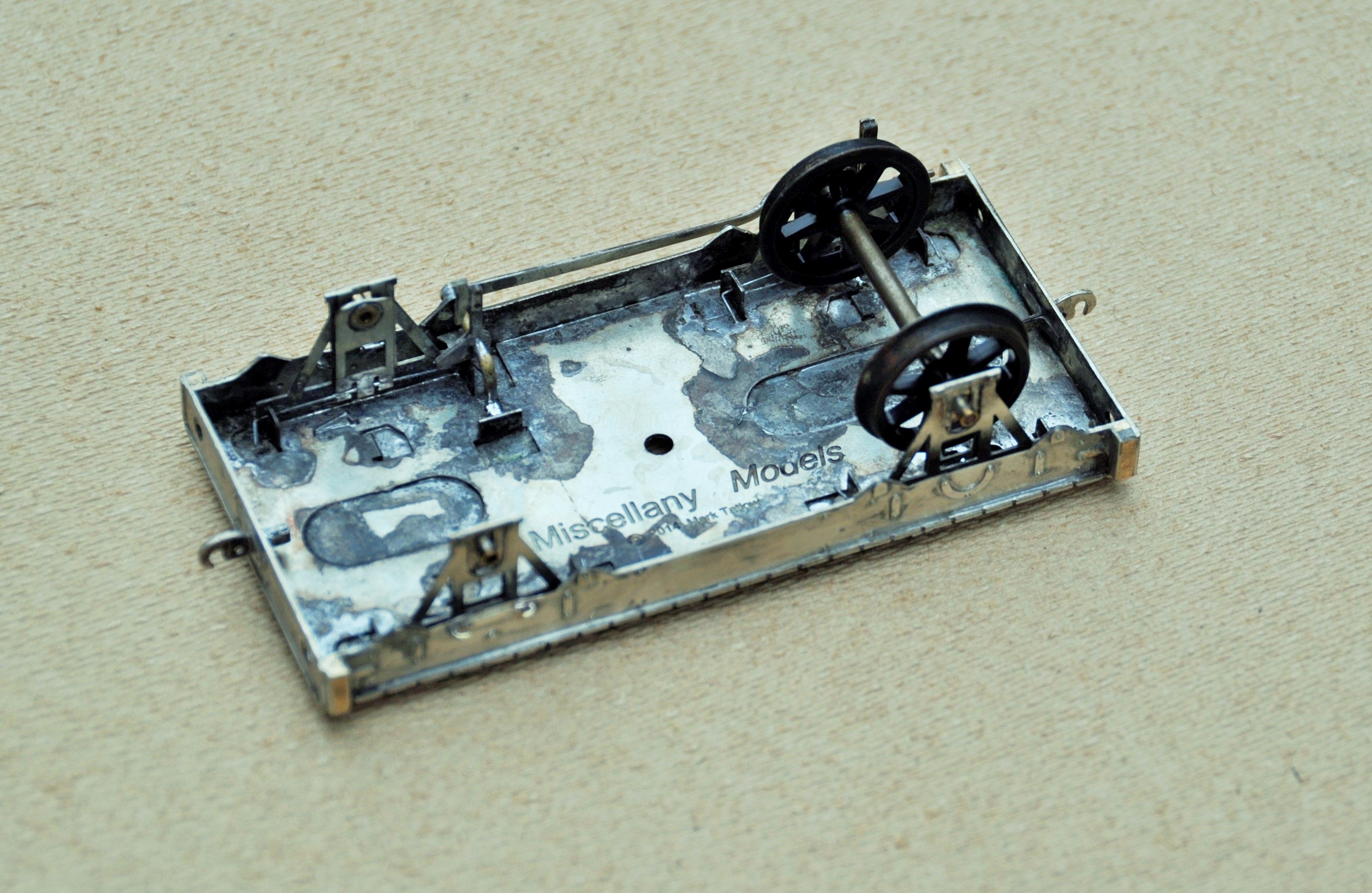
A new website for Miscellany Models
I will be making at least some of the items that I have been developing available for sale.
Therefore, I have set up a separate website entitled Miscellany Models that shows what is available, how to get them and (when I get some time to do it) will become a repository for prototype information that I have on the items I have made, construction/finished photographs and instructions.
You can find this website here. If you look hard, you will see some hints as to what other things I have been working on and are expected to be made available in due course.
Last train to Castle Rackrent?
Last week I was able to visit Richard Chown’s house to have a play with Castle Rackrent at one of his operating sessions.
Castle Rackrent is both an individual layout and also a system; comprising a total of five stations, a harbour and a couple of fiddle yards. It is based on Irish practise, so is all hand built to 5’3″ gauge. Given that the layout is 7mm/1ft, it is pretty substantial and wraps around Richard’s basement a couple of times. This creates the situation where it is somewhat of a challenge to know what is going on in any other location on the system – this does not matter as the stations communicate with each other via bell codes (well, only one adjacent station in our case due to a fault, so we adopted a version of the telegraph system known as shouting!).
It is fair to say, even with this and possibly due to some inexperience on my part, things still get chaotic. We ended up with four of the six possible trains at our station at one point. The normal controller Mr Summers was not in attendance fortunately, otherwise I sense some firm words might have been had………… It was all good fun though and is not really a basis of operation I have experienced before, even though of course all it does is mimic the real thing.
Here are a few photographs; starting with the terminus and original station on the line, Castle Rackrent:
I spent my time (mostly successfully directed by Ian) at Moygraney, so here are rather more pictures of this station:

Immediately next to us was Mount Juliet Town):
It is worth noting the red tag on the rear of the brake van in the final picture above. This is a form of tail light and one of the jobs of the signalman at each station is to check that the full train is there by checking that each train has a tail light. The eagle eyed might also note a few coloured discs on the top of the wagons – these are a form of wagon label; each colour describing the station that the wagon is to be detached at. It all adds to the the challenge of working the line.
The final two stations I have pictures of are Salruck Junction and Lisgoole:
And the reason for the title of this post?
Fortunately, this was not the last train to Castle Rackrent; which will no doubt please the show manager of the Perth show (where the layout will appear in June 14) but it is the last to Castle Rackrent in its present form. Richard has in mind changing the arrangement of the layout and introducing another station. So it was still a historical evening.
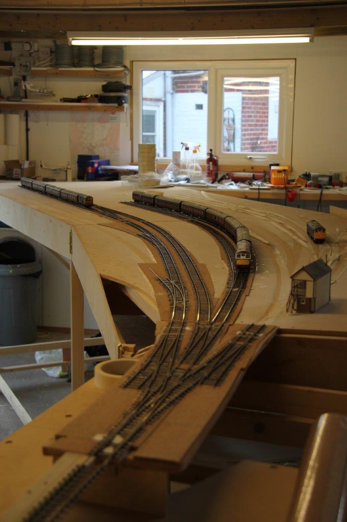
More Baseboards and A Peek at Benfieldside
I managed to get most of another day done on the baseboards at Tim & Julian’s workshops. The bulk of the first four are now done; although the decks are still to be put on these. A slightly fuzzy picture to show the progress is below:
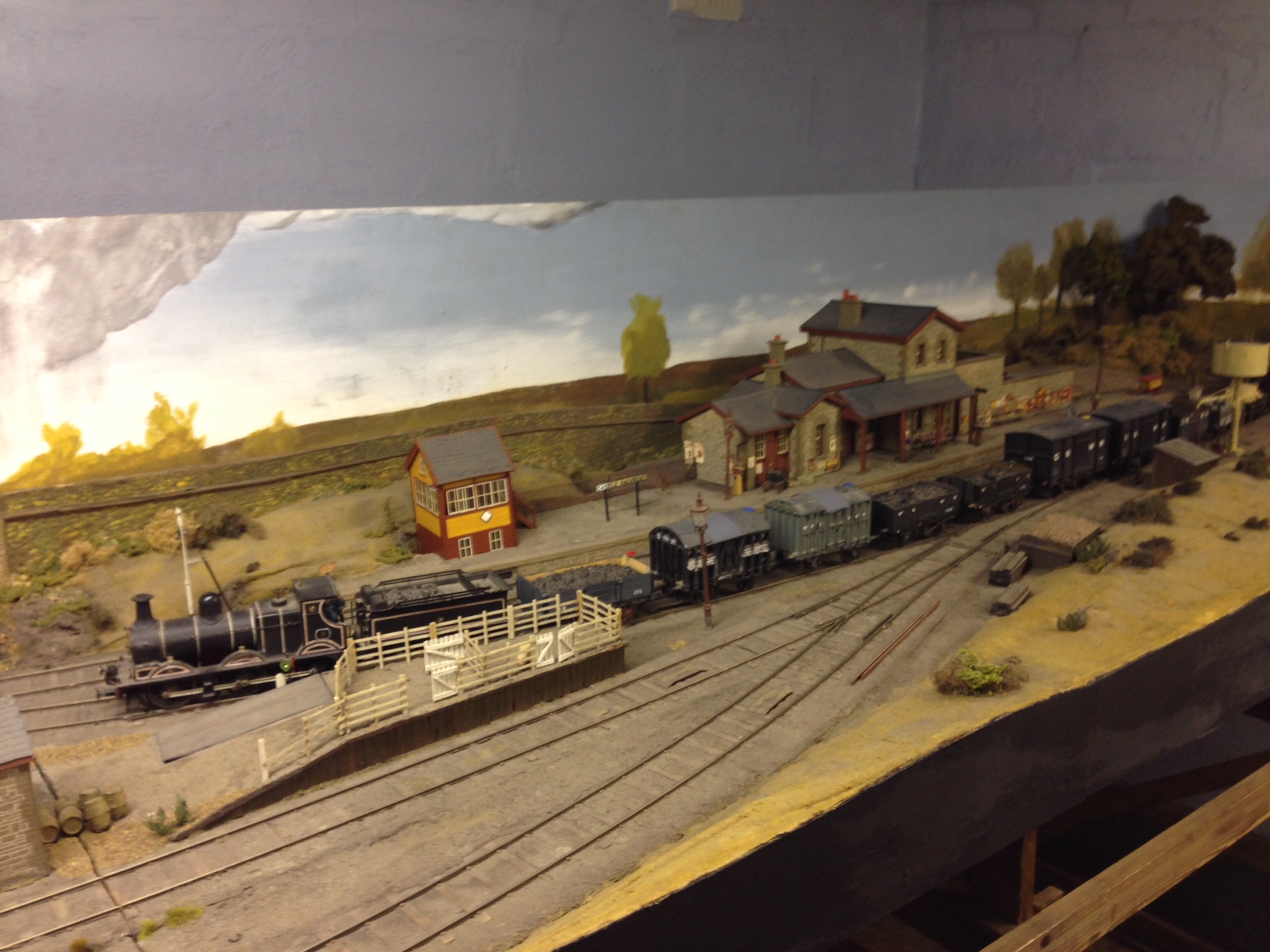
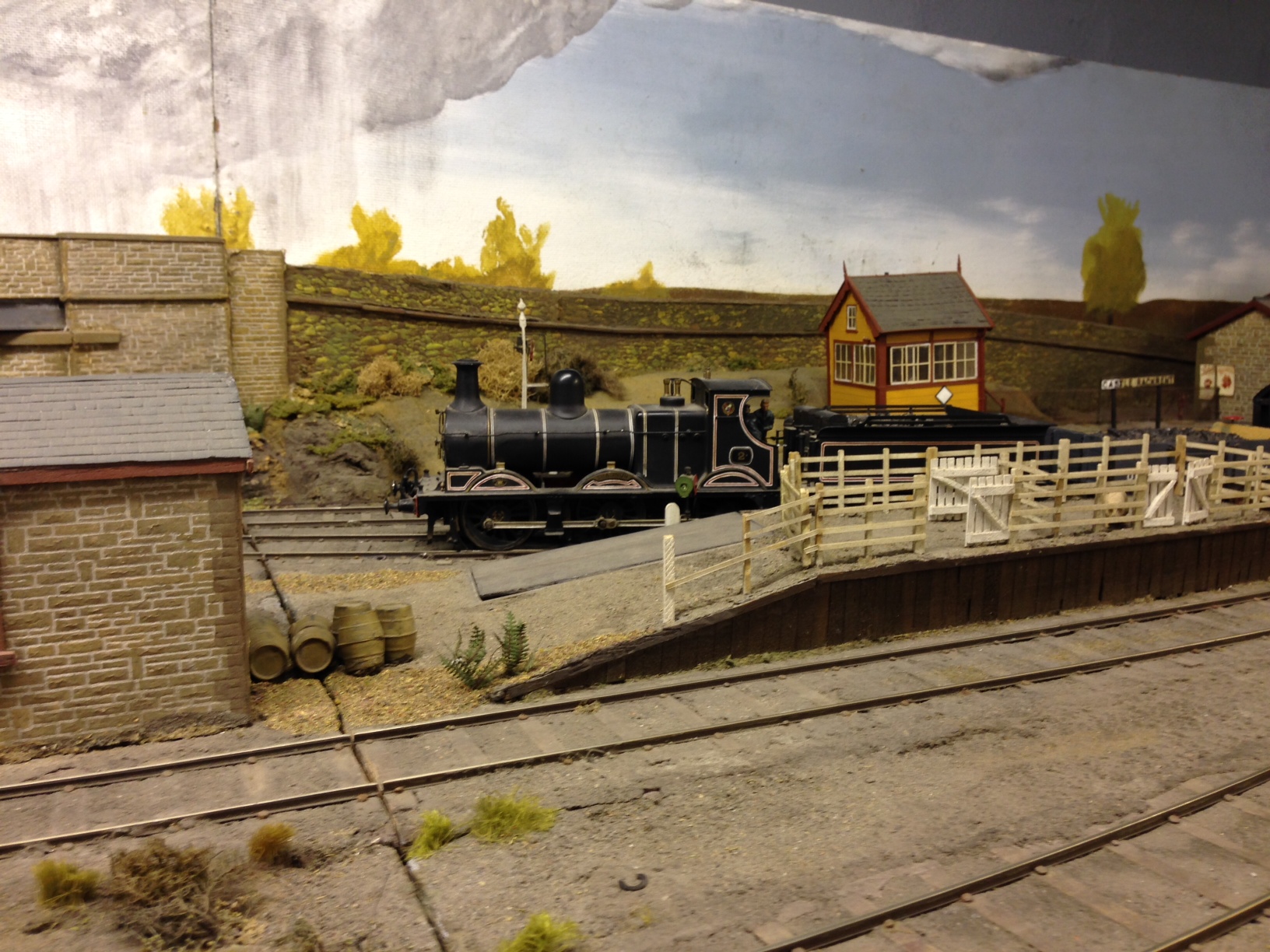
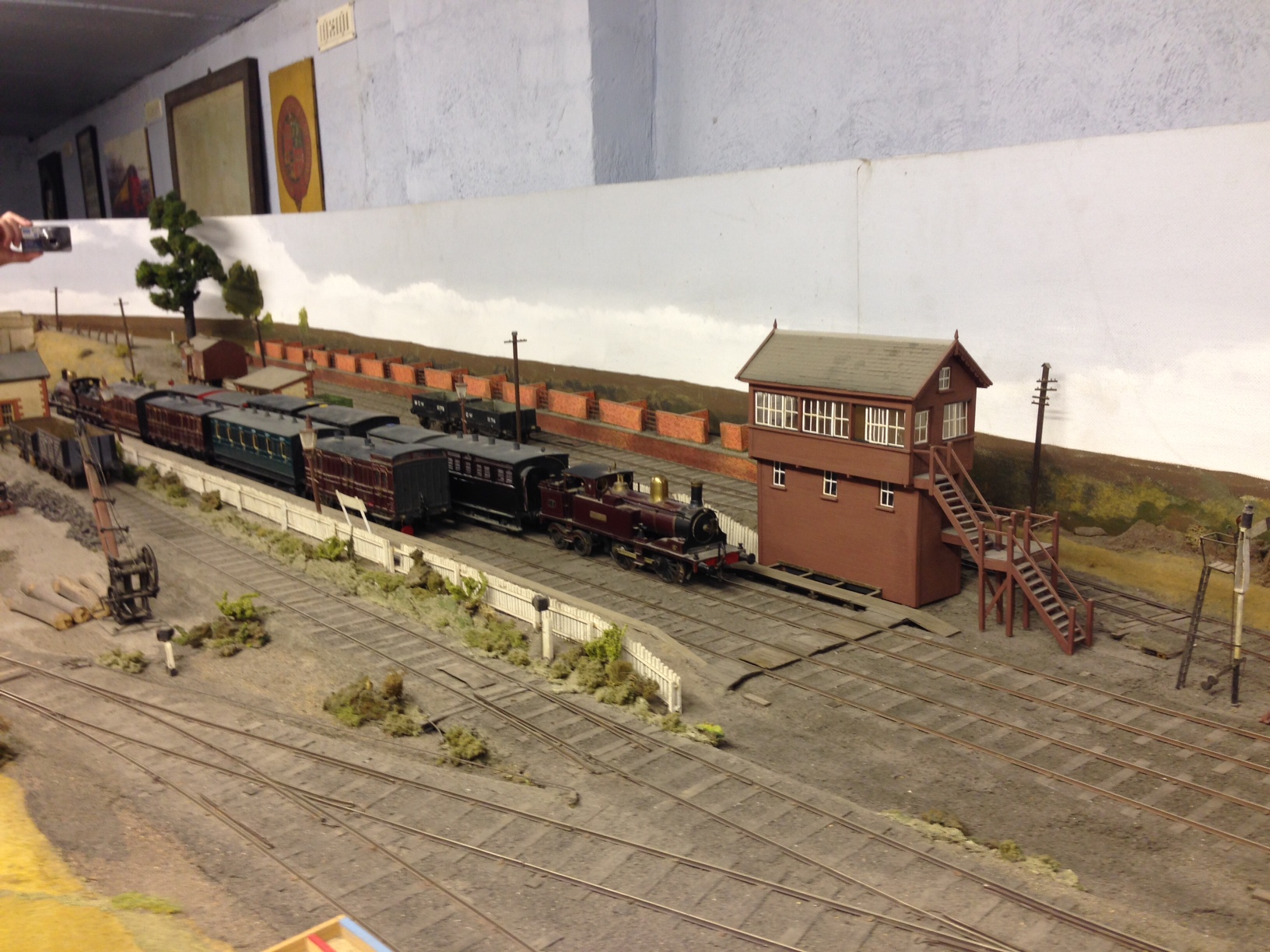
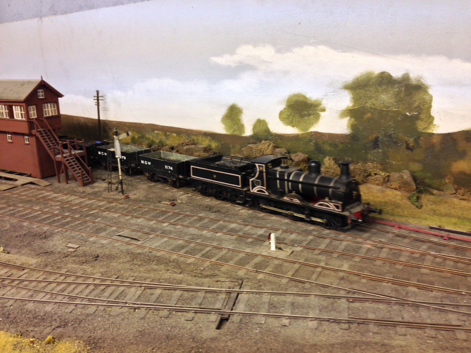
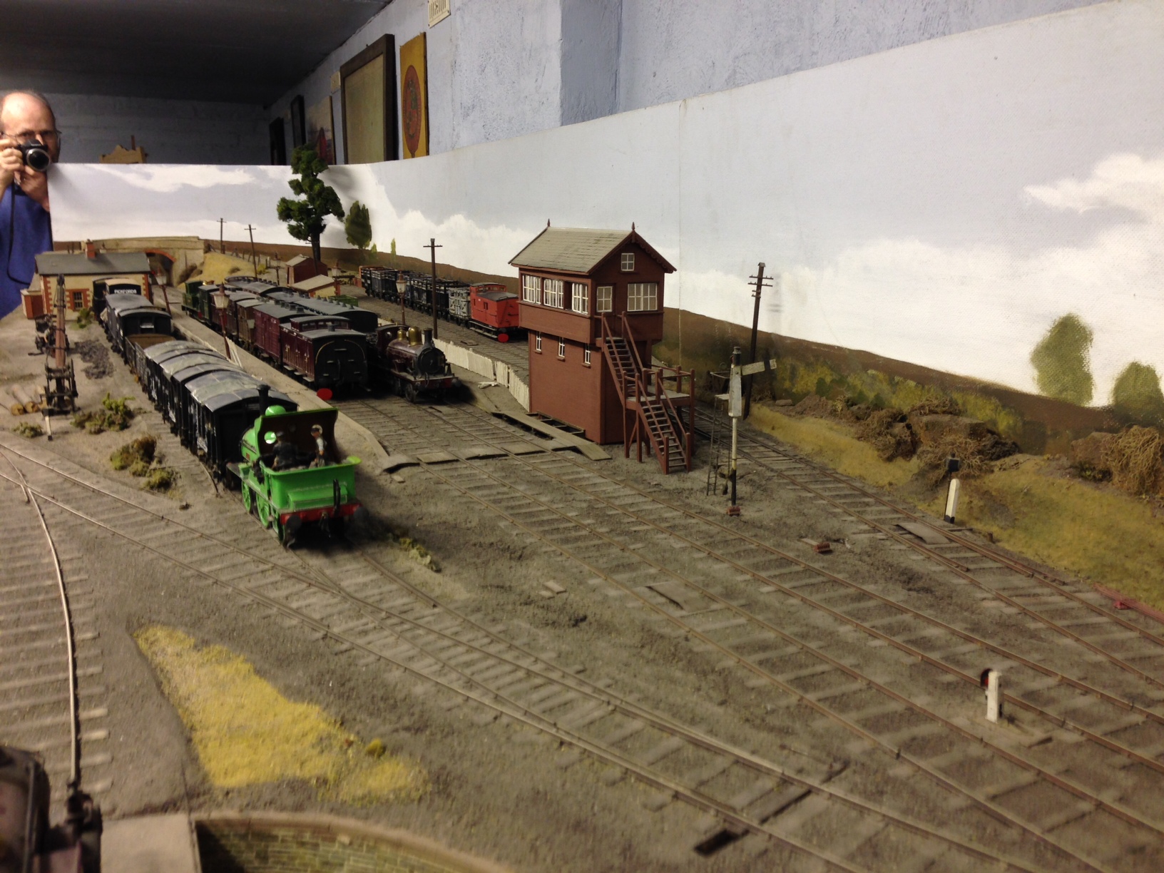
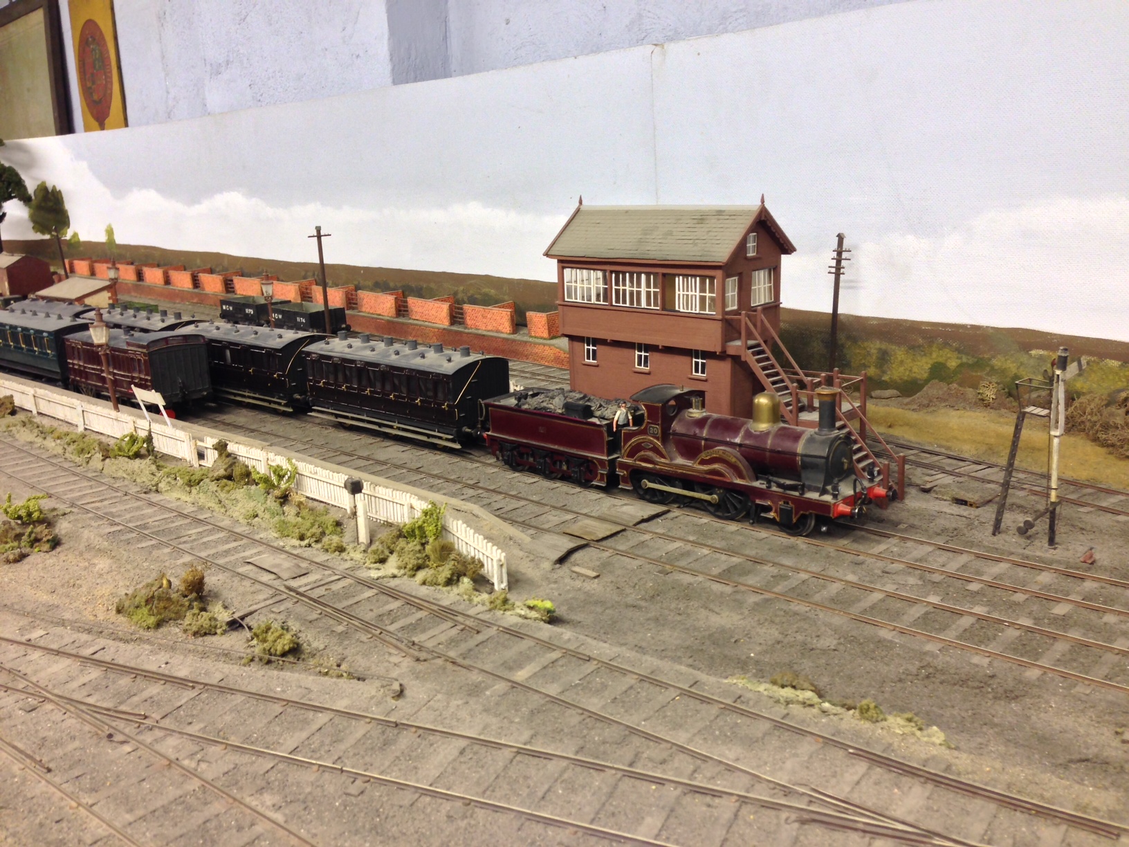
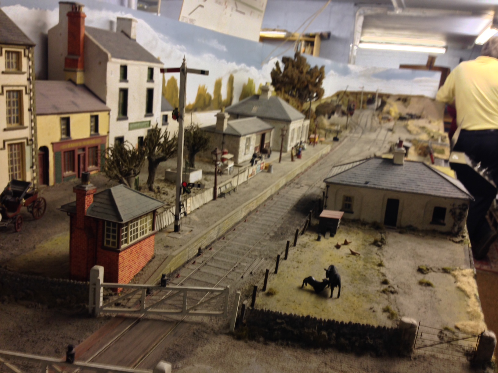
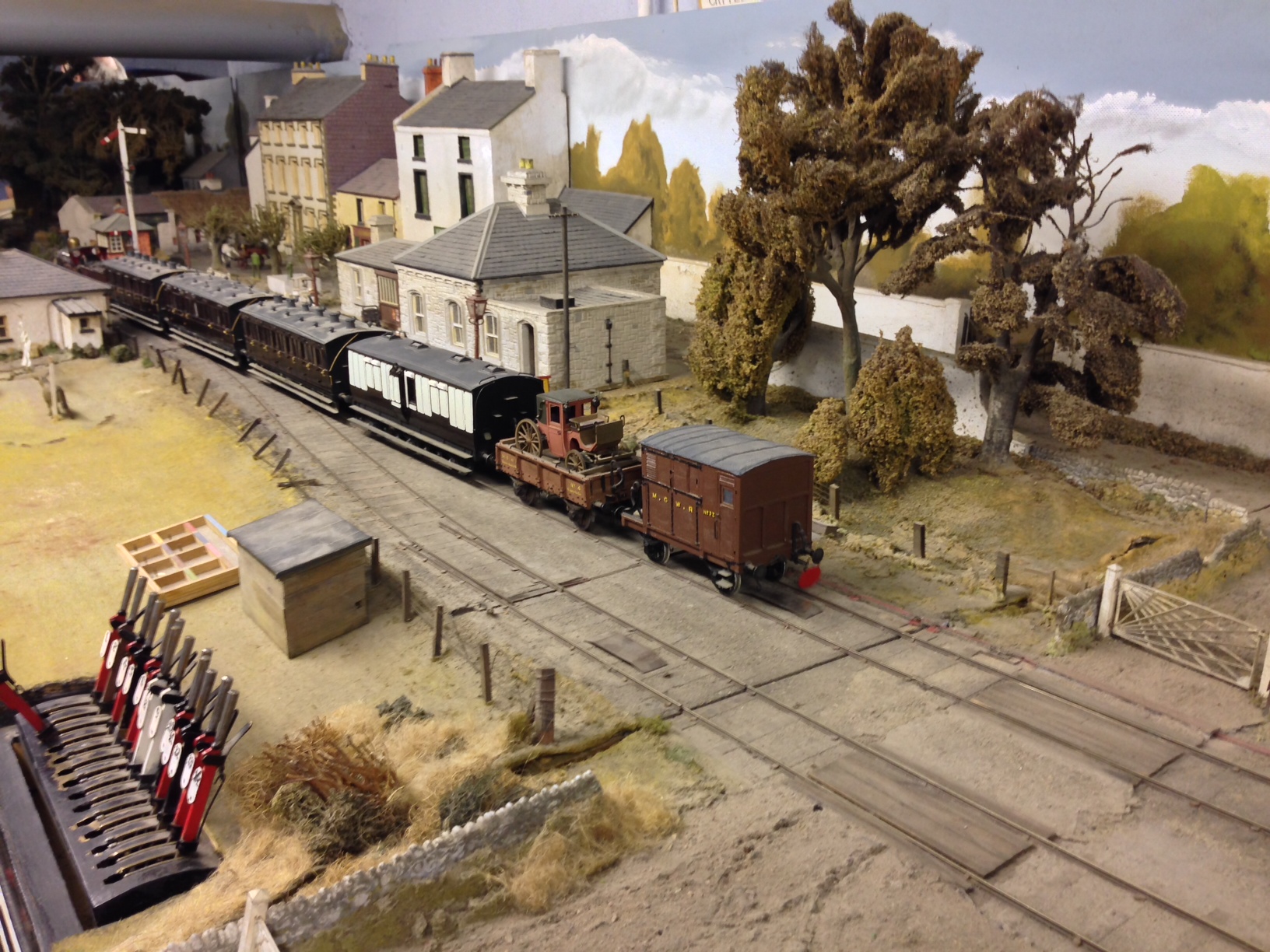
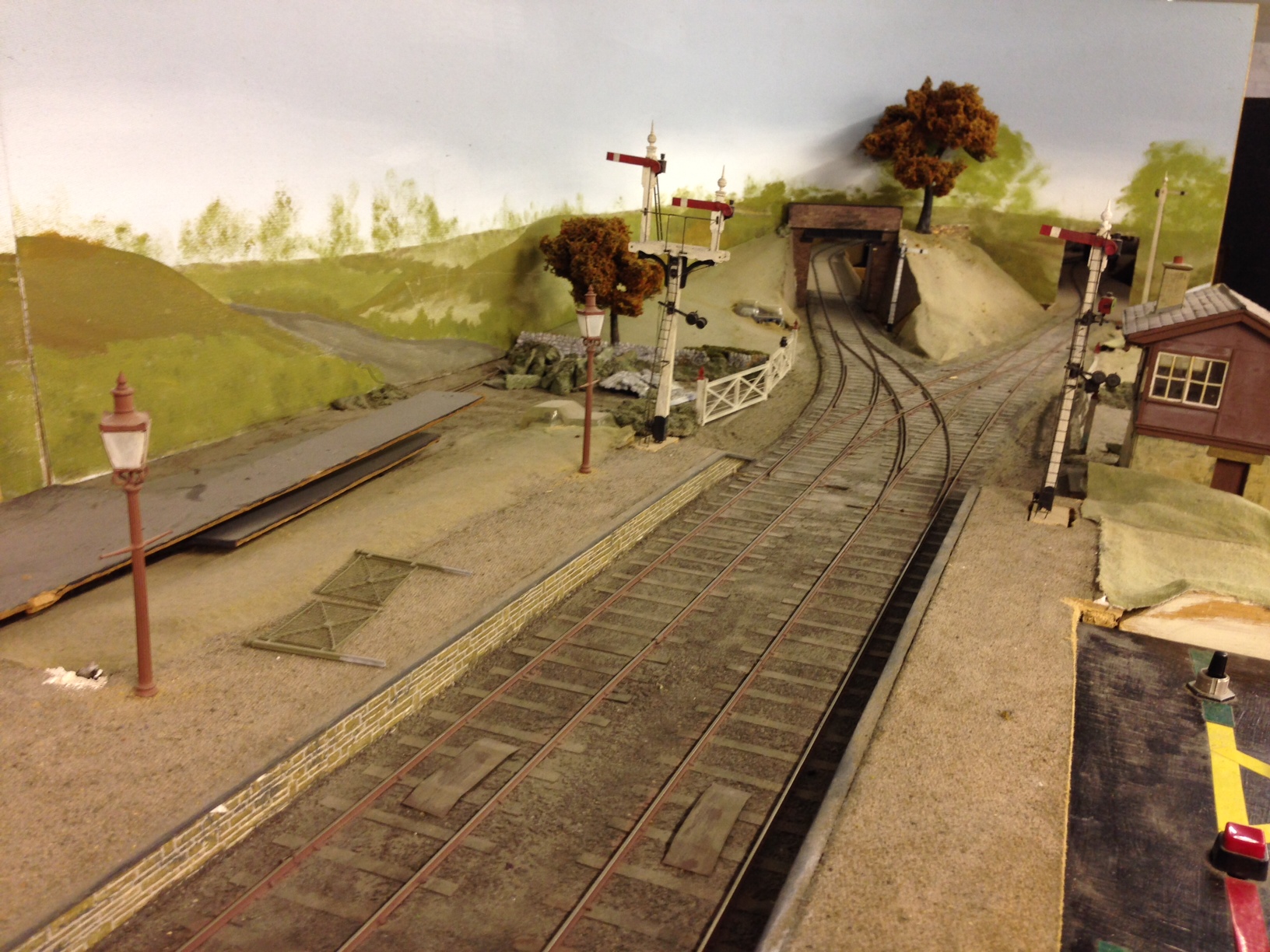
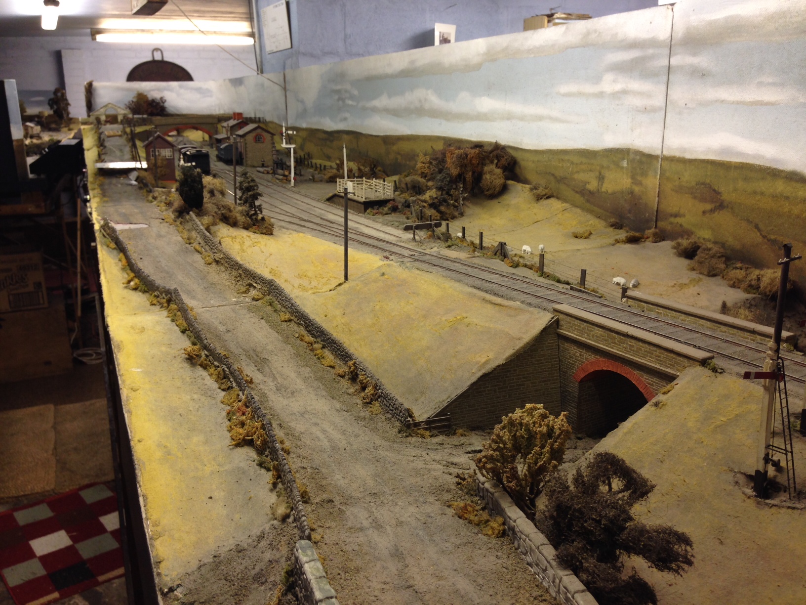
In addition to this, I had a look at their layout Benfieldside. As noted in past posts, they have recently acquired this from John James, who was the custodian of it for some years. Its original building was John Wright.
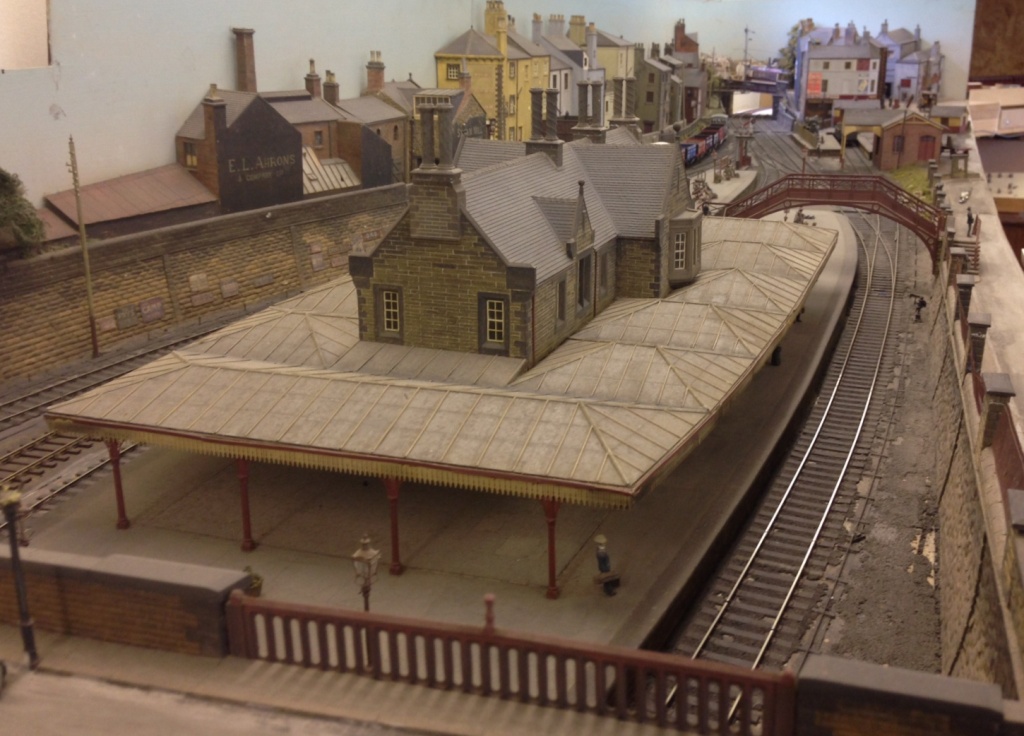
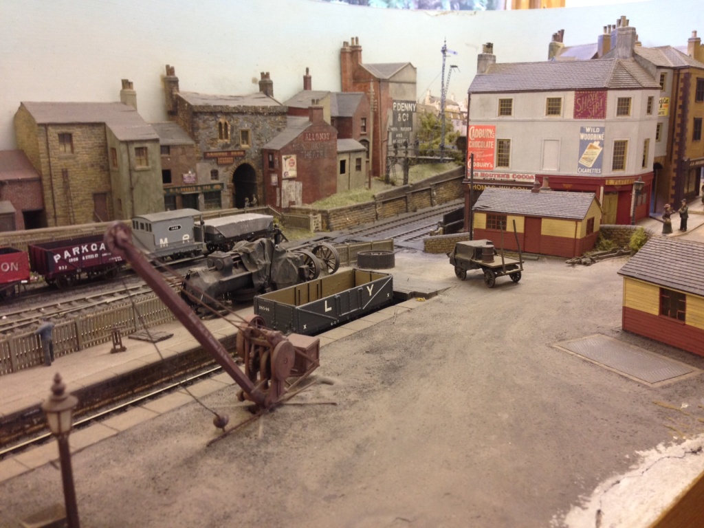
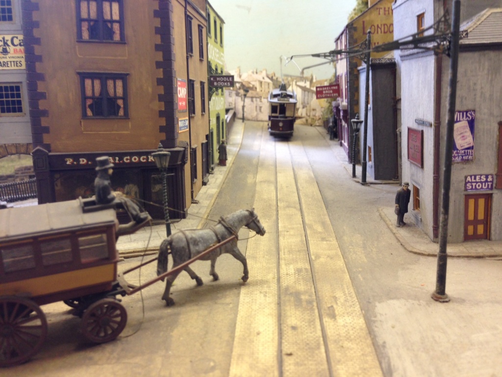
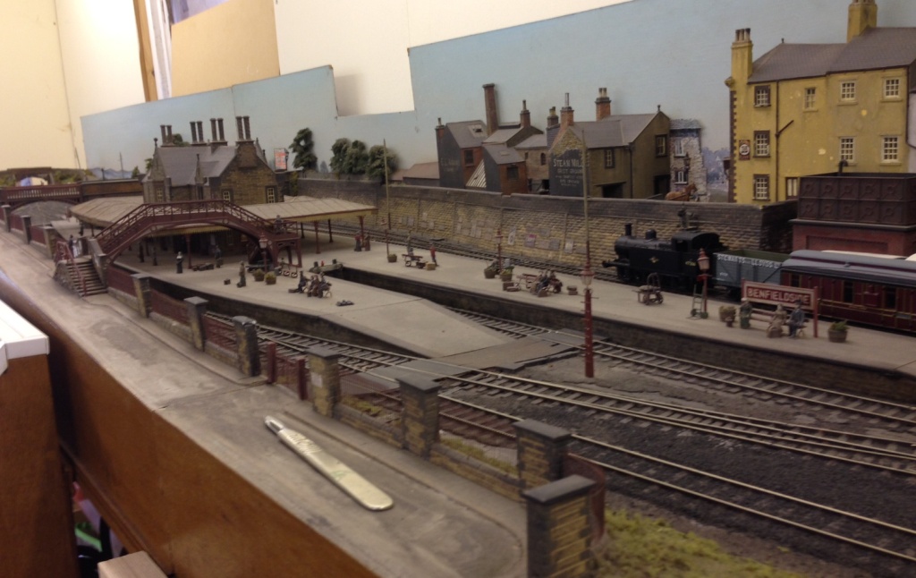
A great layout; I think anyway!
I have managed to restore the first two signals – well entirely rebuild one! I will post some pictures in the next few days with a bit of luck.
