Blog Archives
Swapsie – A Signal for Nampara for Hendrawna (Part 1)
Swapsie – the childish act of swapping things according to Wiktionary.
Do you remember at school swapping a Top Trumps set for a the latest Hot Wheels car or similar? I do! I remember getting roundly b*llocked by my mum for not recognising the value of things I was giving away and (metaphorically I am pleased to say) swapping gold bars for glass beads almost like the Incas and Cortez.
In the world of toy trains, the same happens and is very useful where someone can offer something that you don’t have (or find difficult to make) in return for something you do have. This is one such example. Sitting next to Duncan Redford at an EM Gauge Society/Scalefour Society skills day a few years back demonstrating signal construction a barter was arrived at whereby I would build Duncan a signal in return for him doing some 3D design and printing. I think it is fair to say that neither of us have rushed with our respective shares of the bargain but with the next ExpoEM only a week away, I have shifted into gear to finish the started signal that was my part of the deal.
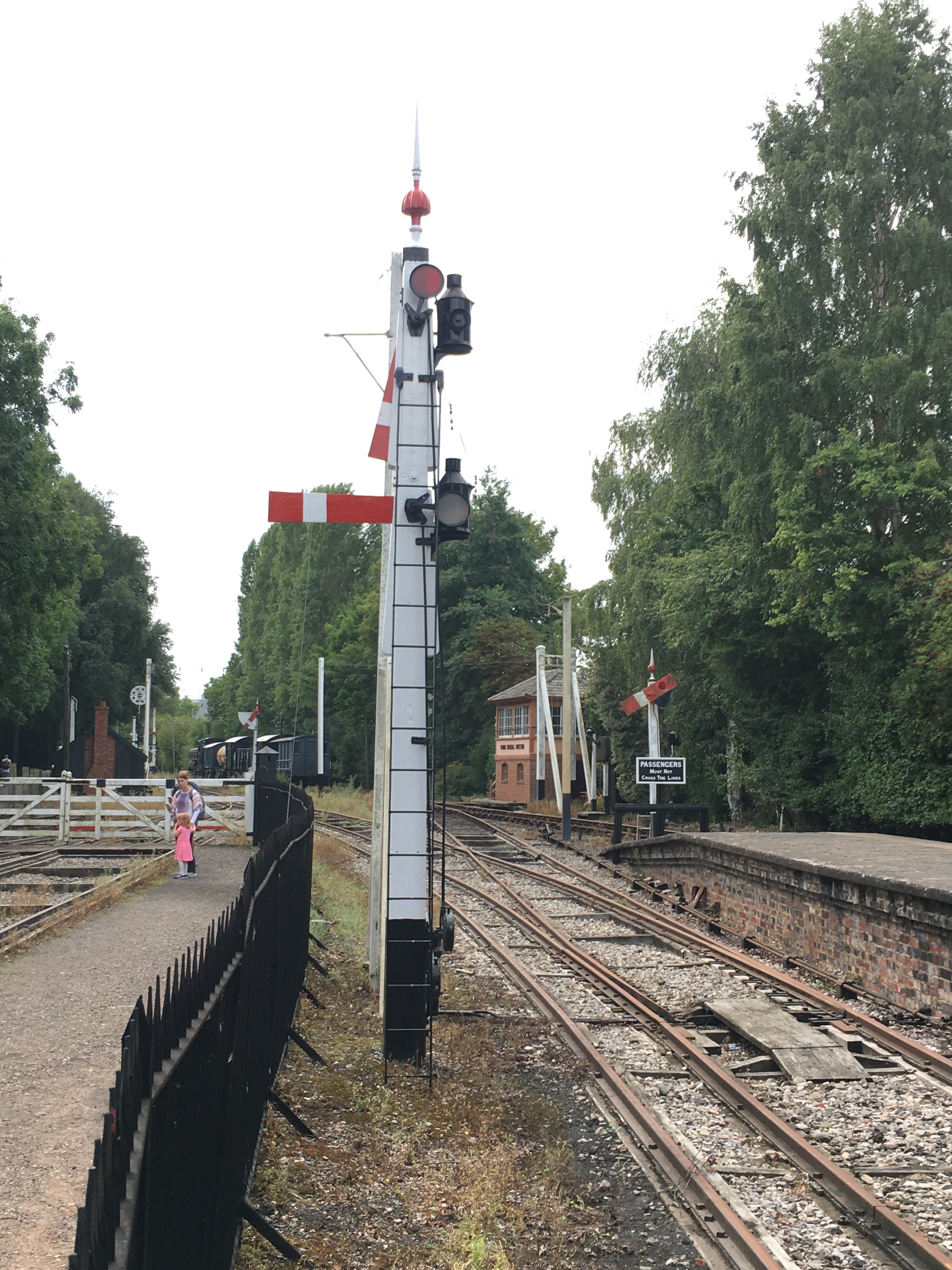
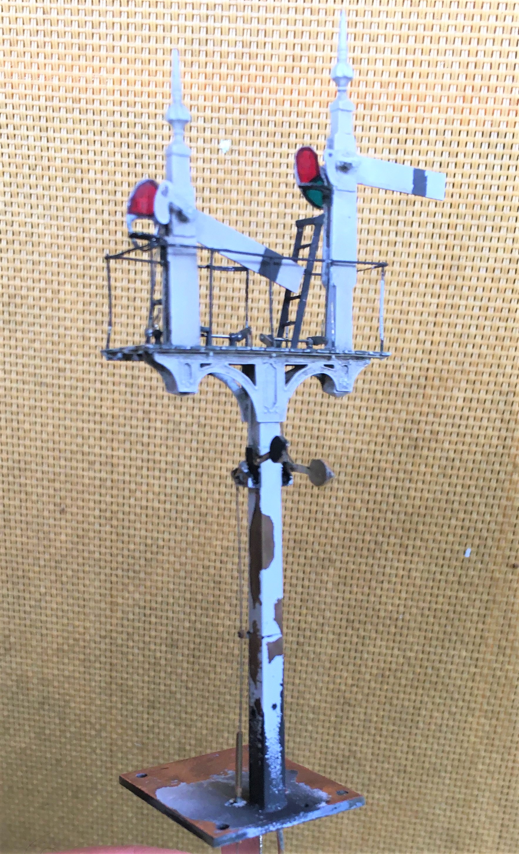
Duncan is building a GWR broad gauge era layout and wanted a close replica of a signal that the GWR Society has recreated at Didcot, but adjusted to have only a single arm. So after coming out in cold sweats about the idea of modelling anything GWR (!!!) I took a look at it. Like many signals, there are differences and similarities with other signals but after a bit of study it became clear that it was sufficiently different that a site visit to Didcot to be required.
Having measured it up including, when no one was looking, a climb to the arm/lamp to measure it, I came home to draw it. I was shocked to find that it was tiny; 3mm/1foot at best and I had a panic attack -had I mucked it up and mis-measured it. Obviously, being a professional surveyor I could not possibly have done that, could I? After a few months, the fear that I had niggled on me and so came about site visit number 2 and a further climb up the signal ladder. Nope, it really is tiny – both the post and the arm are notably smaller than I am used to.

There are several unusual aspects to the signal; the one glass spectacle plate, the tapered arm and the very pronounced stiffening around the slot in the post were all going to be key to capturing the character of the signal. So out came the computer and a small fret was added to an etching order for the arms/spectacle plates. I then formed the basic post from 4mm square section brass which I filed to a taper with a 2.5mm cross section at the top.
Despite having built a few slotted signals already, they are still pretty difficult to get to work well. The difficulty that I have had is to get a soldered joint onto the arm spindle when it is encased in the brass post around it that acts as a heat sink. On a number of occassions the joint has broken and the arm no longer operate. I was determined this was not going to happen this time and have adotped a different approach, by assembling the arm first and then mounting it within the post whilst this was being assembled.
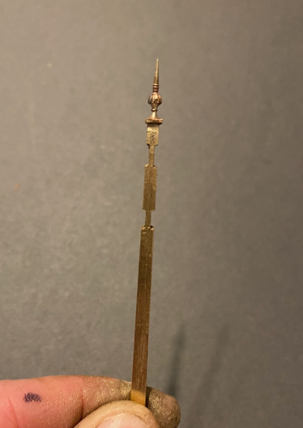
I had filed some 4mm square section into a taper to form the full length of the post. Even though I was about to cut a section of this out, it is necessary to form the full length of the taper so that it is consistent across its full length. Once I was happy with this, i filed two pairs of slots in the outside of the post on oppposing faces. The depth of these was such that the tongue between them was the correct size for the slot in the post. I chose to mount the finial at this stage, with some 296o solder and a lot of heat (from a minature blow torch). This is what it then looked like:
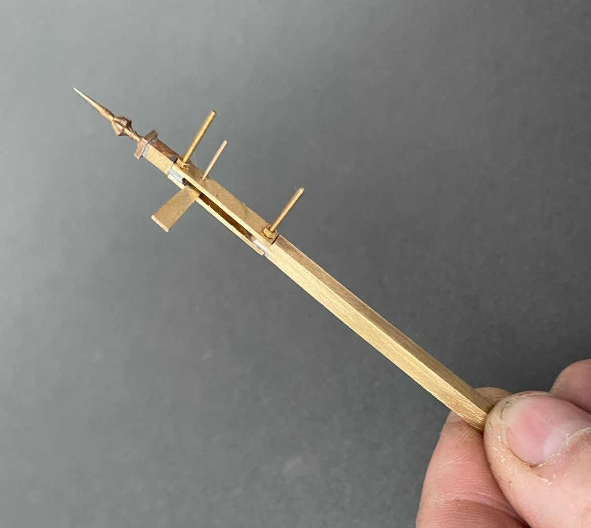
Next, I cut away the block of post that sits between the two filed sections to create a hole in my post. As there is around 2 hours of work to get the post to this point, it is a bit nerve racking chopping it like this! I then cut a pair of 1*4mm brass plate lengths to sit on the tongues and drilled both to receive a 14BA bolt. This was threaded through the first of the plates and adjusted until this a continuation of the taper of the post – this entails some filing of the metal to make the outside face match the post and plate match. It was then soldered in place, again using the 296o solder and a blow torch, to look like this:

The photograph above shows that these plates were wider than the post, in practice the prototype acheived this by planting timbers across these sections but it is easier to do this by way of using the sider plate material.
Temporarily mounting the second plate enables the hole for the arm spindle to be formed through both parts of the arm. The arm was now attached to the spindle with more use of the 296o solder and the use of a couple of minature washers either side of the arm so that I could be confident that the joint would hold.
Releasing the second plate now allows the arm/spindle assembly to be inserted and any adjustments made to ensure that it can move freely in the slot by securing the second plate in place with a 14 BA nut. The nuts and bolts are scarificed in the build by leaving them in place for the next step because once I was happy that it was correct I soldered the second plate in place including the nuts and bolts. This time I used 145o solder which meant that it would not disturb the first plate as I was doing this and this is what it then looks like – a slotted post with an arm within that is firmly attached to its spindle!
More to follow; including the second piece of bartering that I know someone is looking out for progress on!
Only the printable words for this Wednesday!
Hmmmm……..
A signal imitating a Fresian cow was not the effect I was after…………..
Halfords etch primer is obviously not that etchy!…………….. So someone will be waiting a tad longer for their signal than I thought…………

Let There be Water…….3 – Now There is!
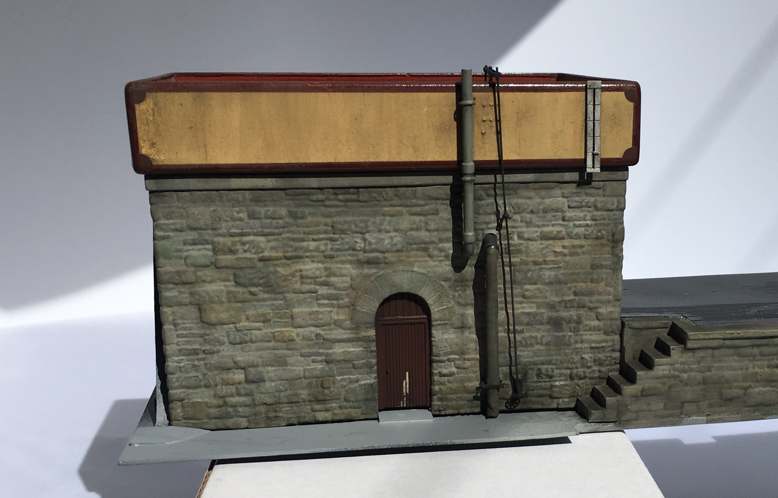
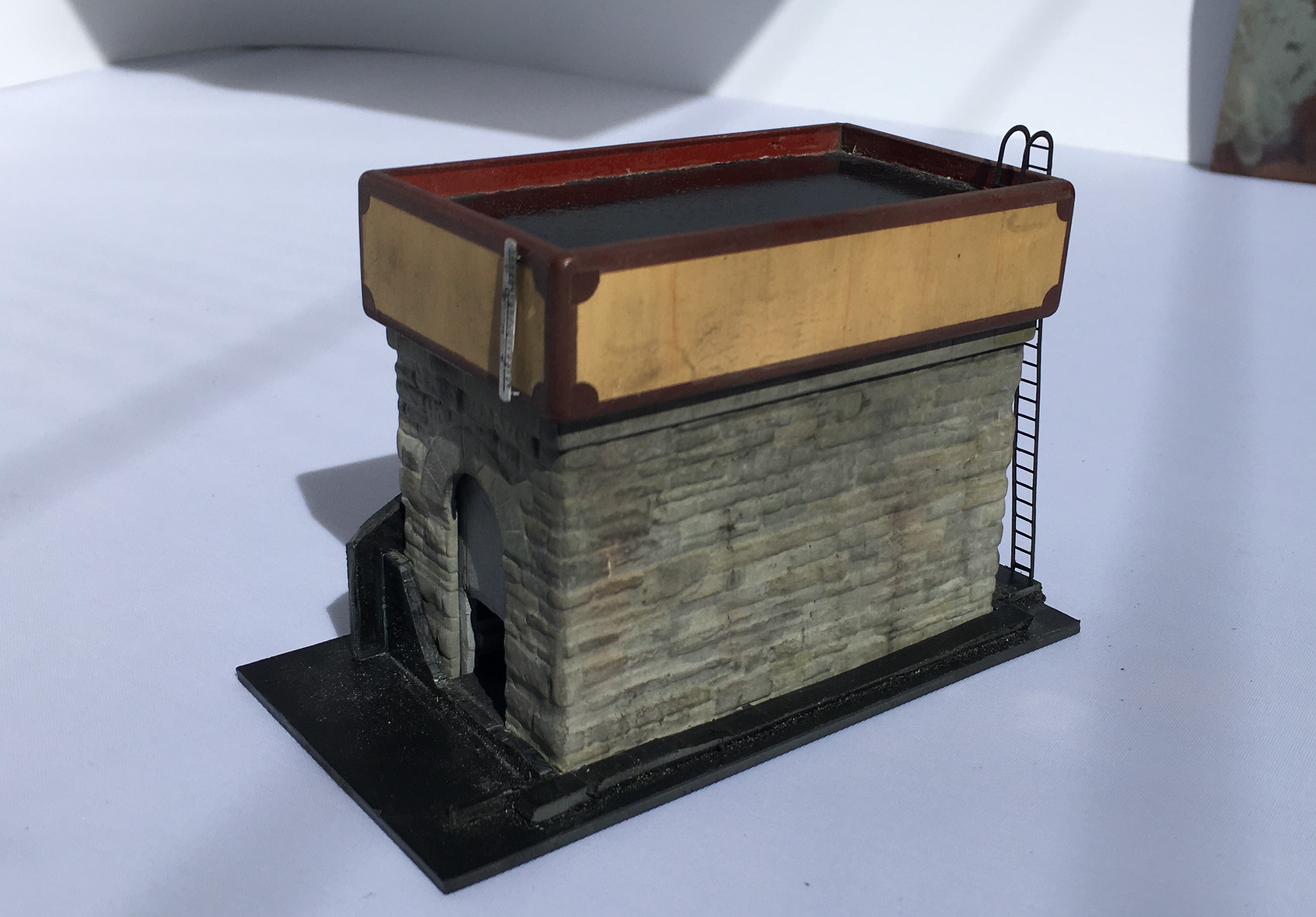
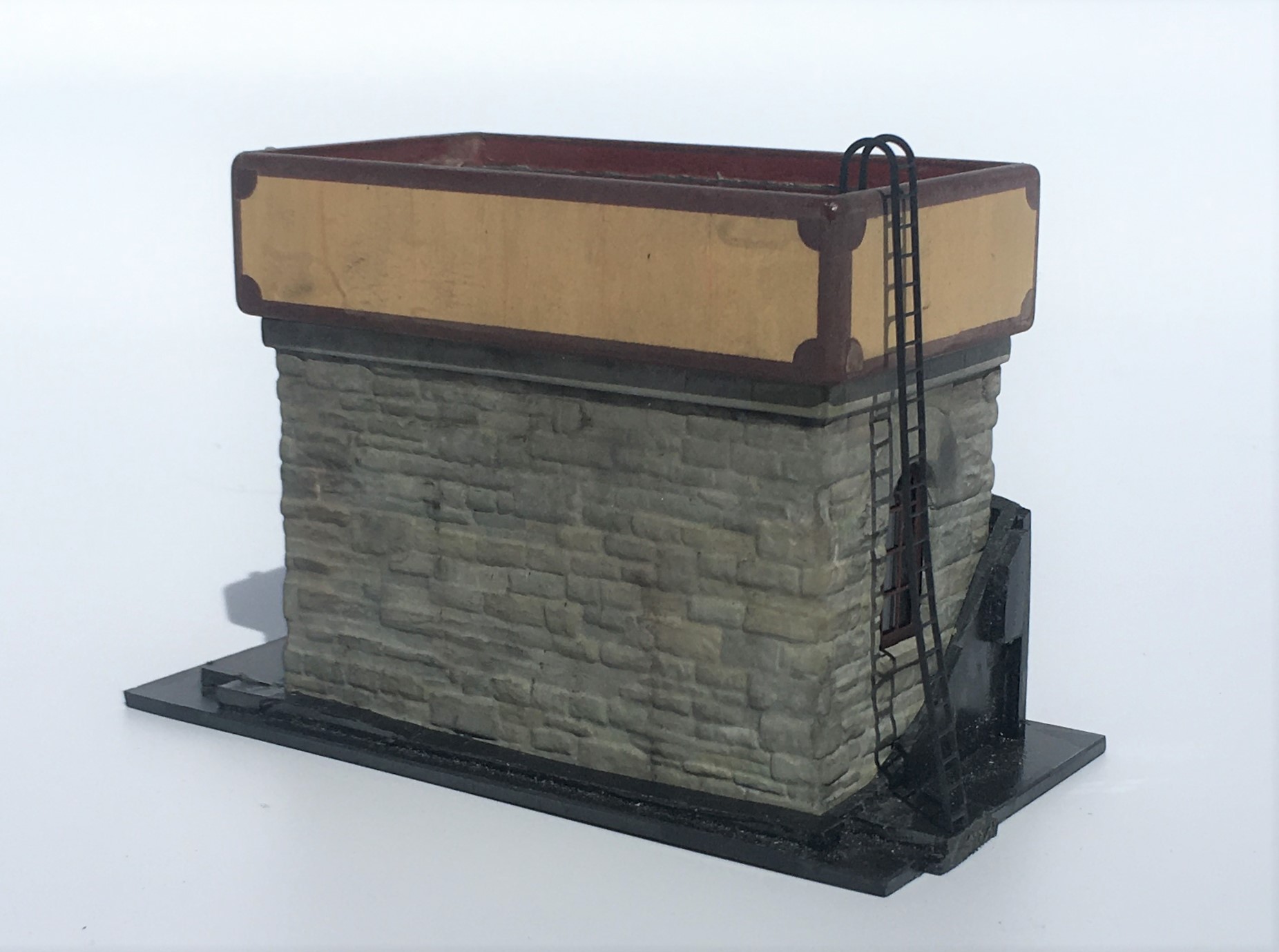
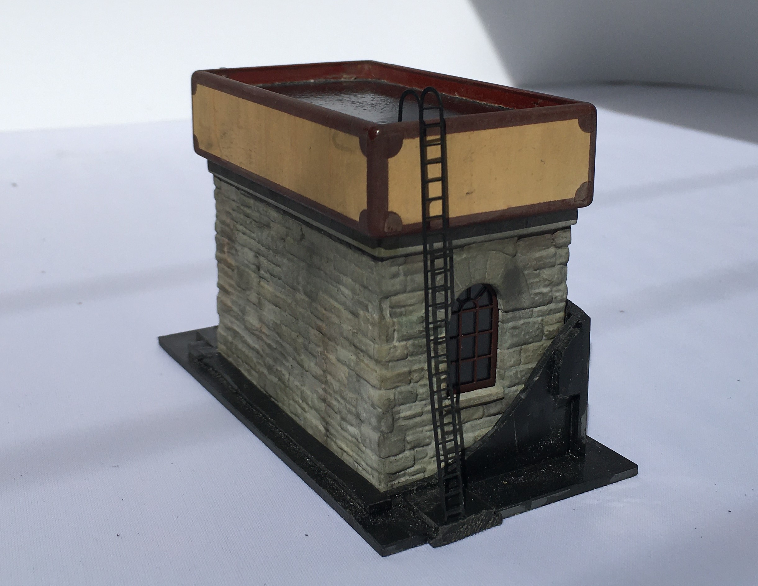
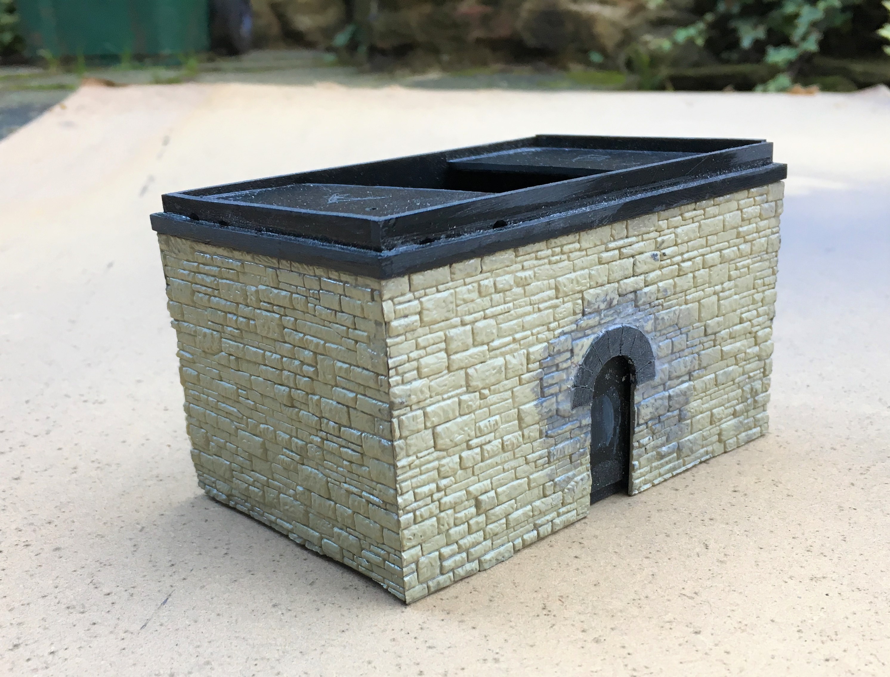
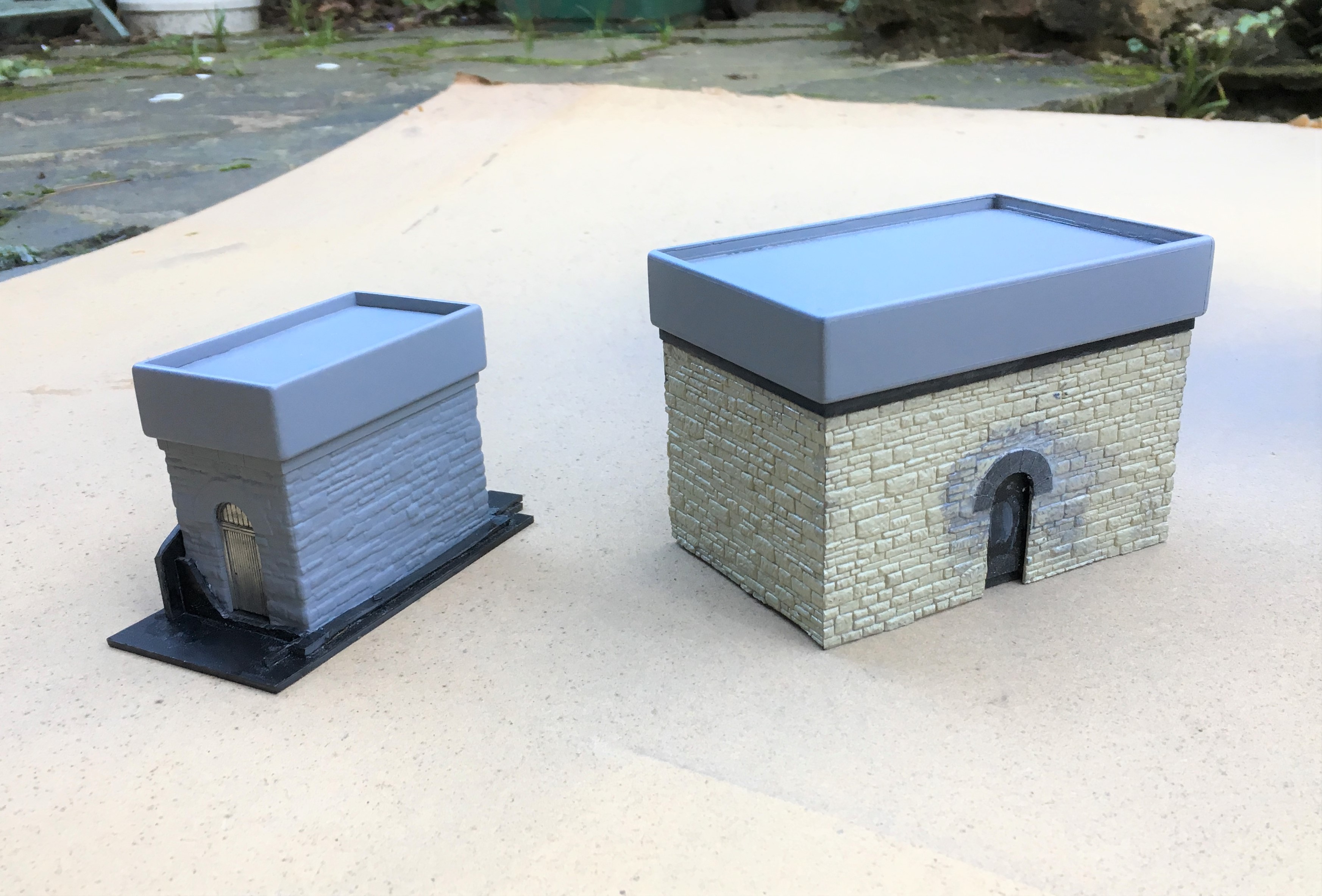
More progress has been made with the pair of water tanks and they have now reached the stage where they are effectively finished.
The stonework was painted by picking out each stone in different colours. I think there is a real art to this as when I see others do this, I often think the colour differences are unrealistically abrupt. I find the trick is to use a core of two colours that are close to the general colour that you want – in my case Humbrol Matt no 5 & 64. Put these in separate palates on a mixing dish and dip into these to create a combination of the two.
By selecting two relatively close colours, you can alternate from all one to all the other and any mix in between. Adding very moderate amounts of a stronger colour difference, in my case Humbrol Matt 66 and 62 which are a darker grey and a leather brown adds a bit of variety but in each case they still need to be mixed in with the two core paints to keep the toning consistent.
Even with this work the colours didn’t seem quite real, so I completed two additional steps. The first was to use some matt varnish that I knew the matting agent was a bit gone on – this gives a slightly translucent milky effect over the whole and drew the colours together a bit. The second was to use AK Abteilung 502 weathering powders – black smoke, ashes grey, gunmetal and rubble dust (primarily because these were the only colours I had!). These need to be used with care, as it is easy to put way too much on and you can’t generally get it off again! However, at low level and to the coal bank I have been pretty liberal with particularly the black smoke as such areas were far from clean!
The weathering to the water tanks was dealt with slightly differently, although it also started with the use of the acrylic varnish with the defective matting agent (that’ll be how I found out it was defective!). I then used a Humbrol dark grey was with downward brush strokes and then wiped off with a piece of kitchen roll, again with a downward stroke. A few additional marks, especially to the panel joints, with AK Interactive weathering pencils.
The water effect was another accident flowing from the defective matting agent – the milking was far from desirable on the black base coat of paint. Thus, I wiped it off once it was semi dry and I got most of it but where the remainder was still there, it added a bit of texture to the surface, as if there was a little disturbance to the water that affects part of the surface not the whole.
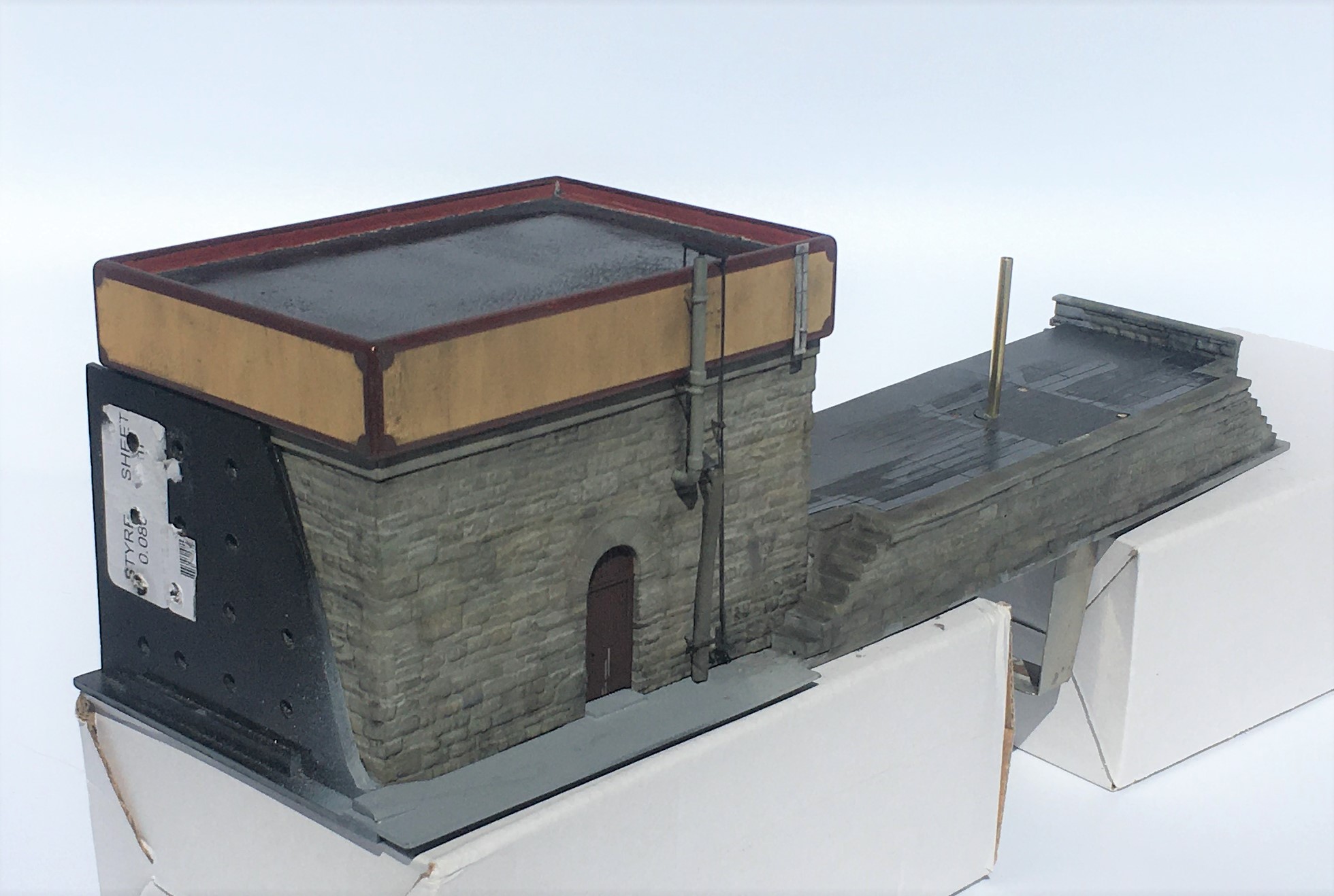
By reference to the prototype, I made a heating stove flue and spigot for the water bag from brass rod. To form the bends it was necessary to have a pair of additional tubes inside each other to stop the tube collapsing on the bend, The canvas section of the leather bag was formed by a piece of heat shrink sleeving but with a little 5 minute araldite in the centre such that as this starts to cure a degree of shape can be put into it and once fully cured it will stay in this shape.
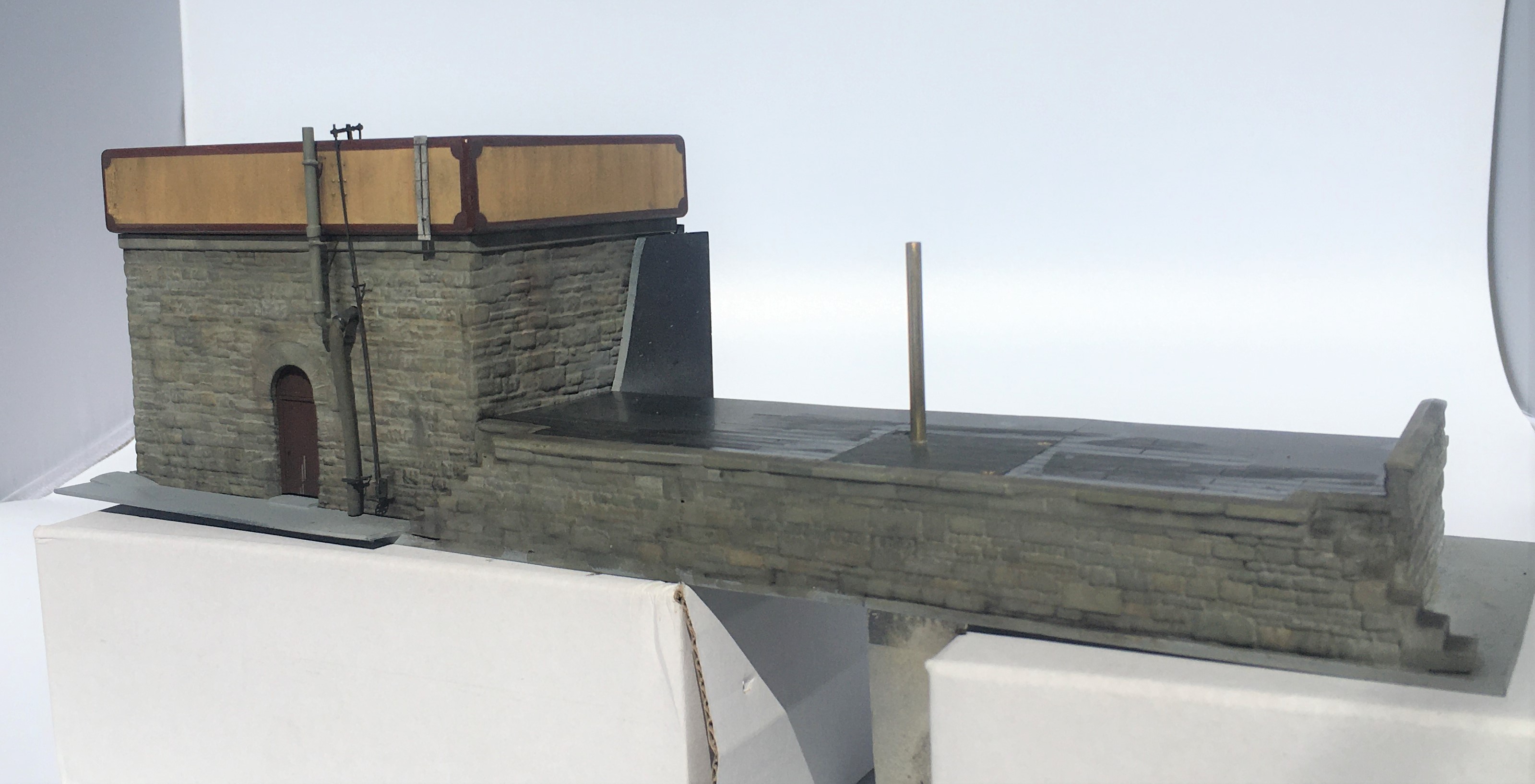
The operating rod was based on that still largely apparent at Altnabreac and I have assumed this also had a ladder even if this has now gone. There is no watering bag to the smaller of the two water tanks as I propose to have some water columns, but that is a story for another day!
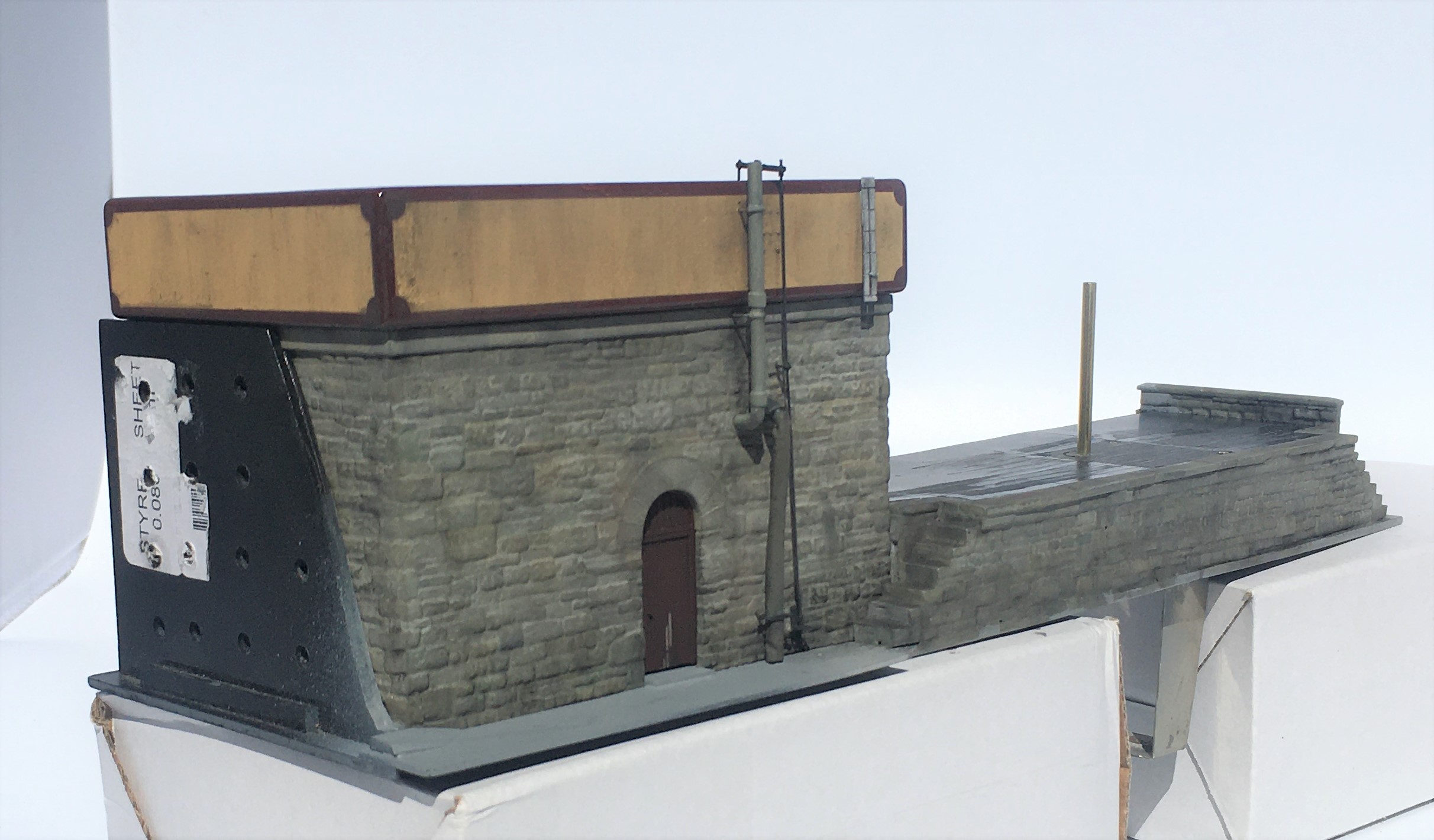
A further story for another day is the rather odd post sitting in the middle of the coaling bank; but that story will be fairly soon!

Let there be water……..part 1
Part of the concept of the back-story for Glenmutchkin is that it is at the end of a long line so that locos need to be serviced and it was also at the foot of a steep gradient, so trains need to be banked out of the station. All this is creates a lot of thirsty locomotives that would have needed servicing and attention – so it will have a busy motive power depot.
The Highland Railway’s water tanks tended to be of a similar style with a tank made of sectional components and rounded head, base and corners. There is nothing available from any of the manufacturers so it was obvious these need to be scratchbuilt.
There remains one tank of this type still in situ, at Altnabreac which I will describe in the next post. In addition to this, there are drawings from Eddie Bellis of the Kyle’s water tower and also of Garve by Henry Orbach. I have elected to build a pair – one of Kyle and one of Altnabreac (the latter being the smaller).
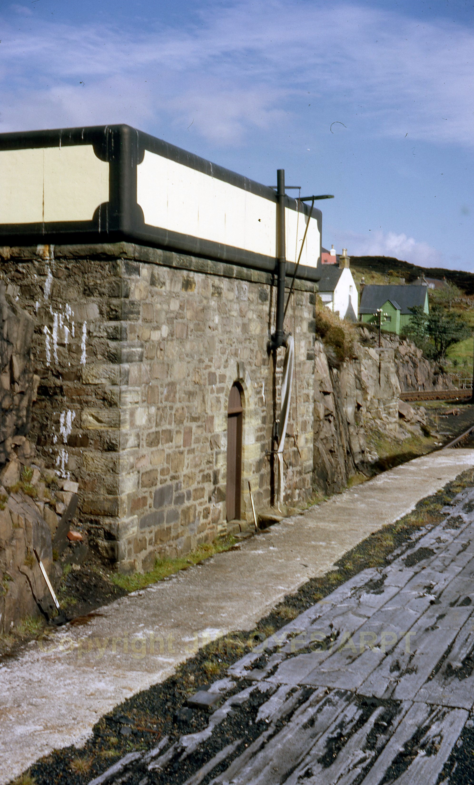
Kyle’s water tank from the early post steam era. Photograph with permission from Armstrong Railway Photographic Trust, JM Boyes collection.
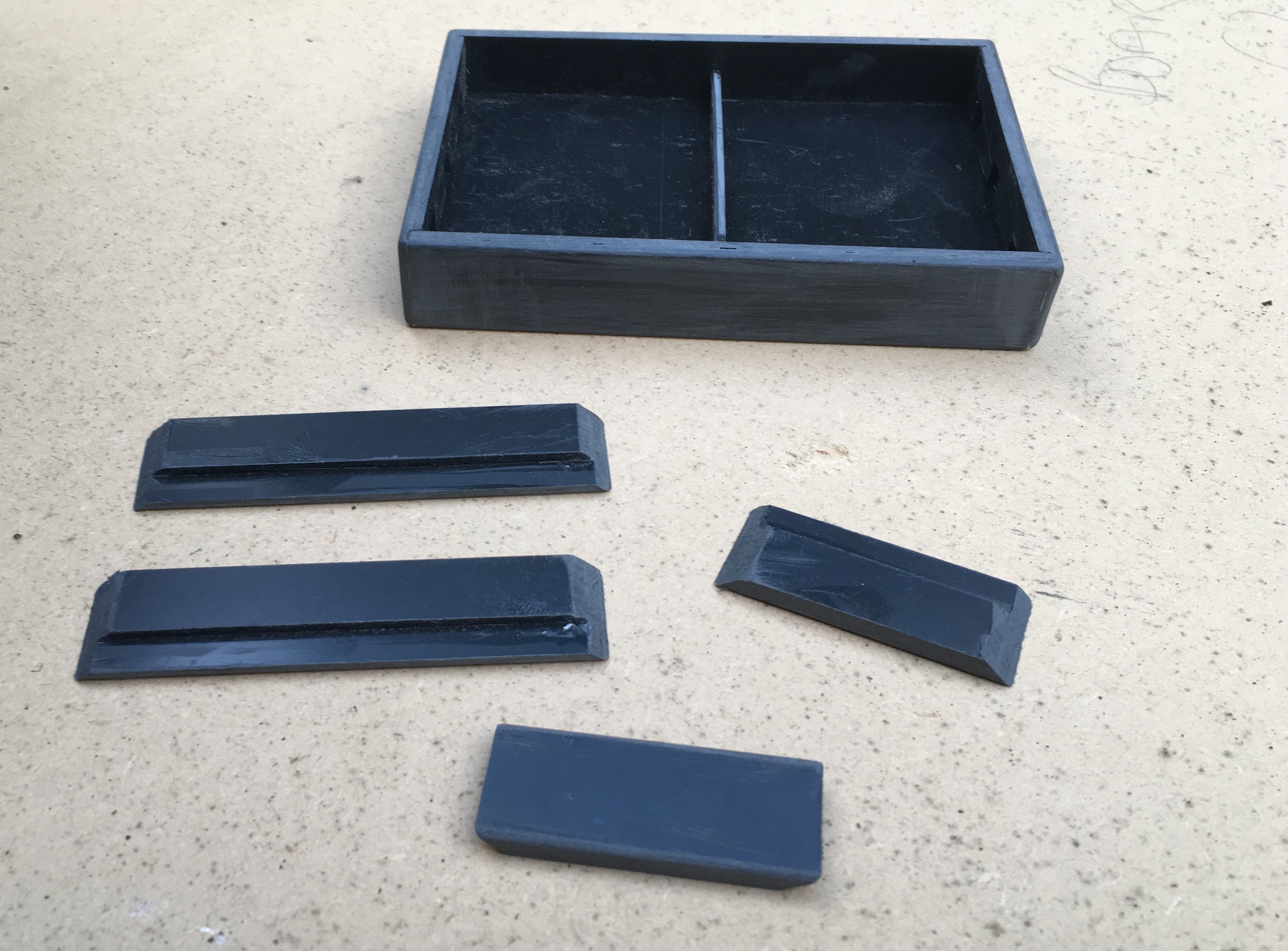
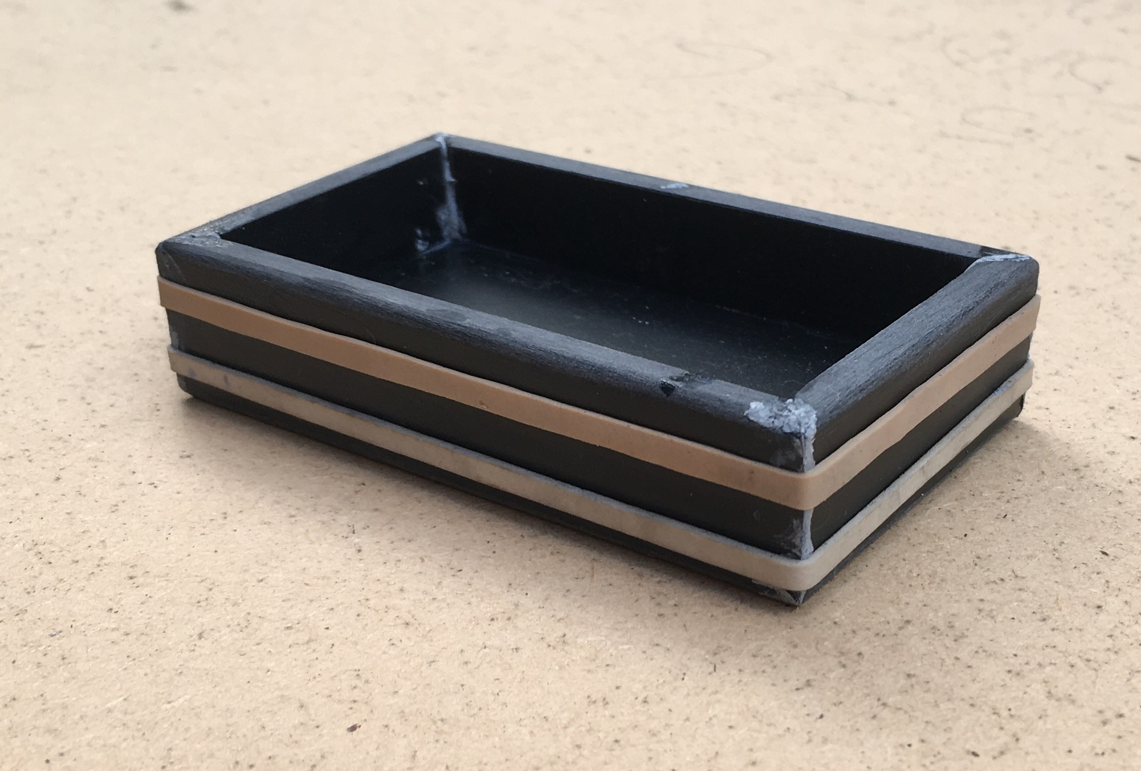
Starting with the tanks, I laminated a series of strips of plasticard to the right height and then used a belt sander to put the chamfer on these before then making them up into a box.
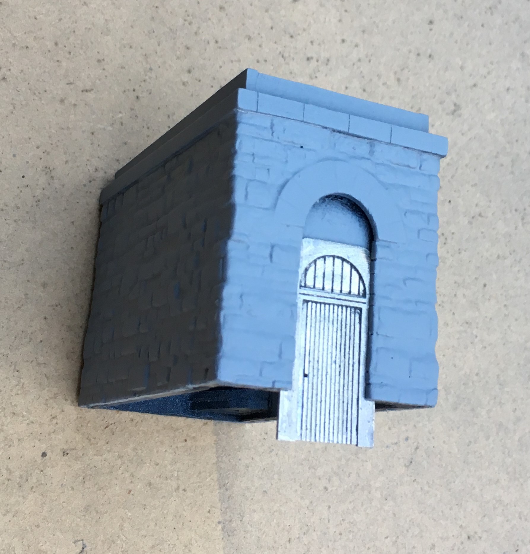
As with most of my stone buildings, I use Wills random stone plastic sheets; now available from Peco. On far too many occasions I see this used with panels butted against each other; either on corners or even worse on the flat. Unless the stones are toothed into each other, this screams as being incorrect even to a layman. Therefore, it is best to form corners either from a sheet cut vertically and then chamfer the inside faces so that the coursing is retained for its full length even on the cut face.
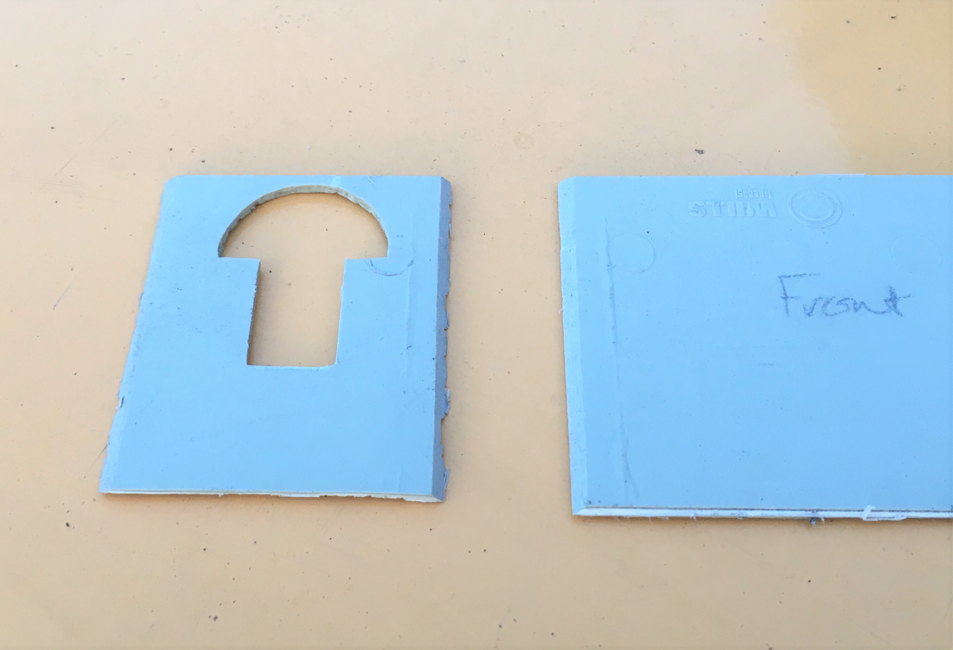
This means that courses line up from side to front without any silly jumps, as can be seen below. This technique can not be used in all examples and sometimes it is necessary to actually tooth panels into each other by cutting corresponding dog teeth into adjacent panels.
I find that the mortar courses on Wills sheets are a bit too deep and because lots of others use it its pattern is a little too obvious; so it looses its realism (or maybe I am just so sad that I can tell a material by its stone coursing!!). I get over this by part filling the mortar courses with a plastic filler – which is basically dissolved plastic in a solvent carrier (lovely and smely!). This tends to distort the sheets as it is only applied to one side so I first laminate the sheet to some thick (1.5 or 2mm plasticard). Due to the volumes of solvent to be sloshed around in constructing buildings in this manner, it is important to allow for the solvent to escape – regretfully I have a number of coach roofs which many years later have mushy sections where the solvent has been trapped and has distorted the plastic in its efforts to cut through it and escape! I thus drill regular holes or slots in the backing plasticard, which you can see here:
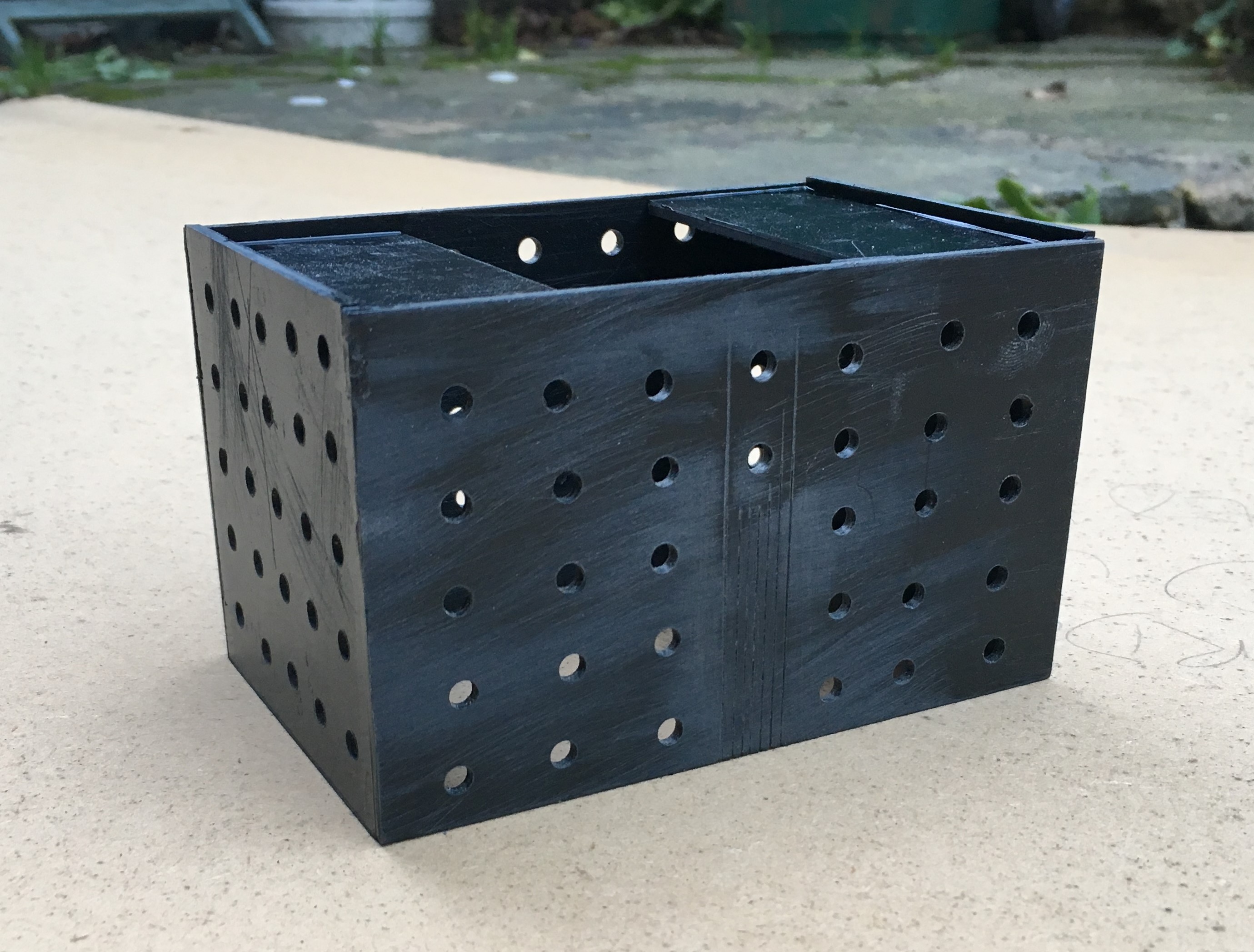
Whilst the desire to mask the coursing pattern on the Wills sheet might seem a fair amount of bother given the need to reinforce the walls with an inner laimanate, I think the effect is worth the effort. A blast of grey primer shows that the coursing and texture of the stone is retained but equaly it does not look like everyone else’s!
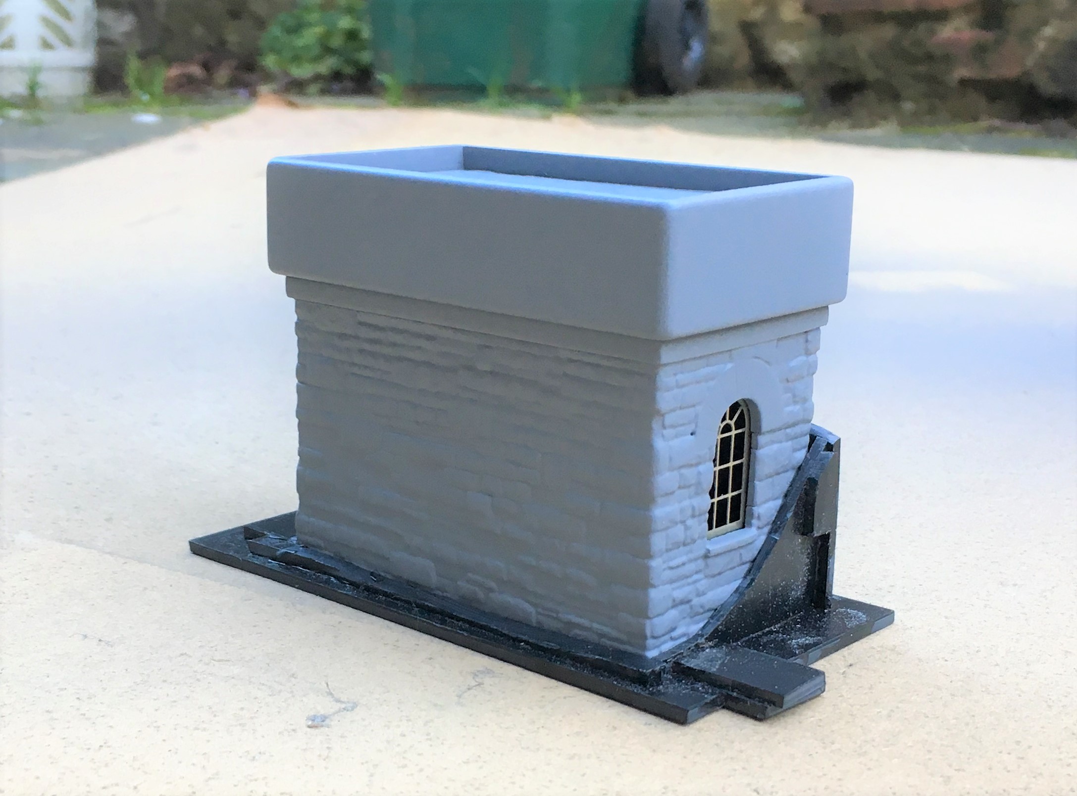
The use of the laminations does give the advantage that slots for window frames and doors can be created. These allow an etching to be slid in, either from below or behind. They can be slid out again for painting and make this aspect a breeze to do.
And this is where they have got to; the guts of both done but with a chunk of detailing and some basework still to be done.
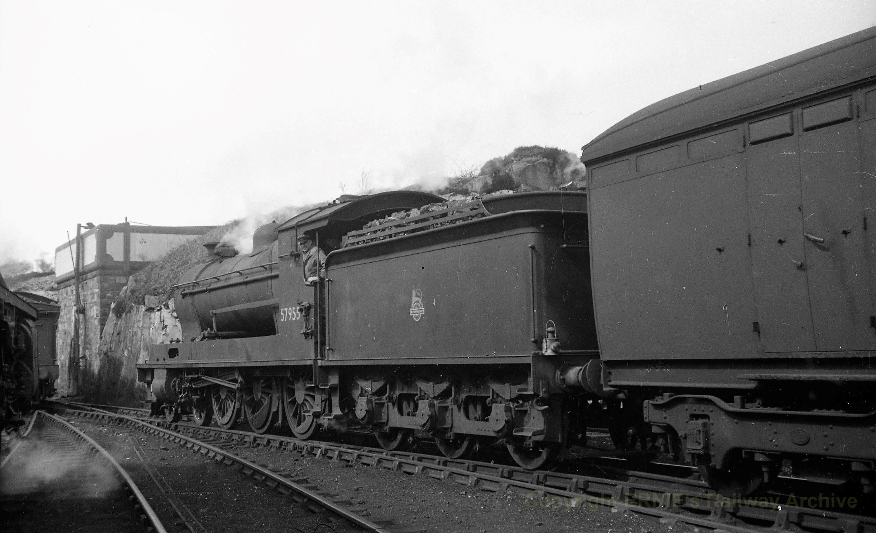
But lets sign this post off with a fine HC Casserley picture of a Superheated Goods using the MPD as a headshunt in the early 1950s. This photograph is used with permission and is now part of Ernie Brack’s collection. He has a substantial on line collection of photographs (including the JM Boyes collection) with a good proportion of them being of the Highland’s system – you can loose many an hour in his flickr site – this being a link to his Dingwall & Skye album.
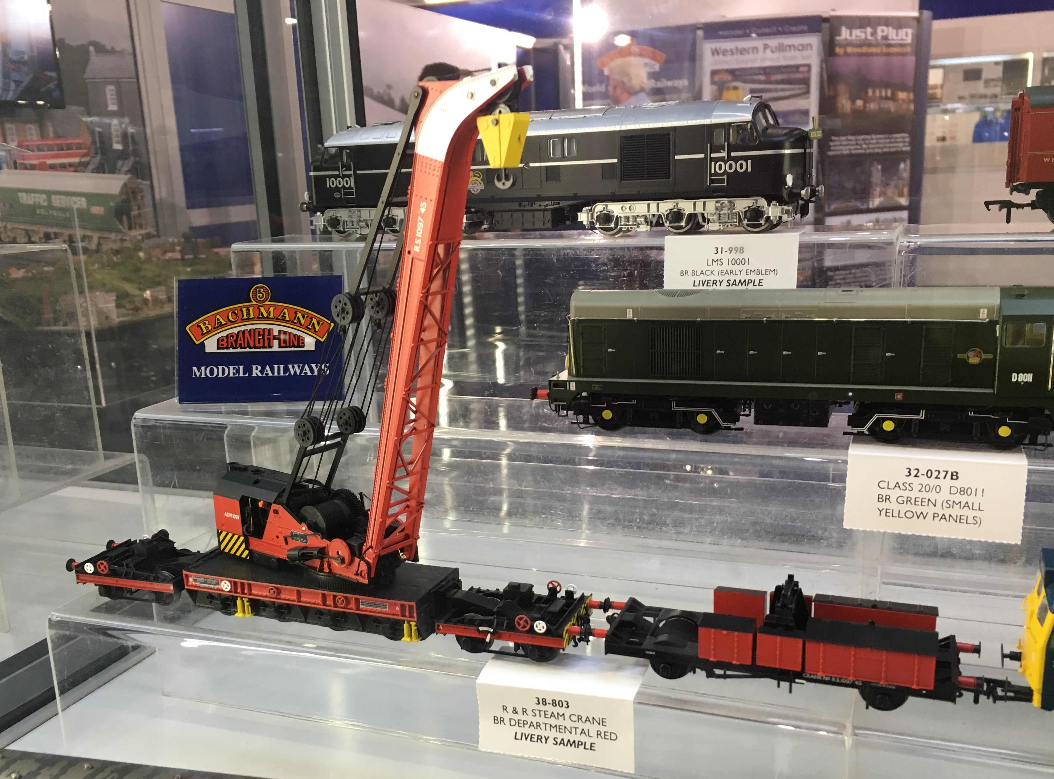
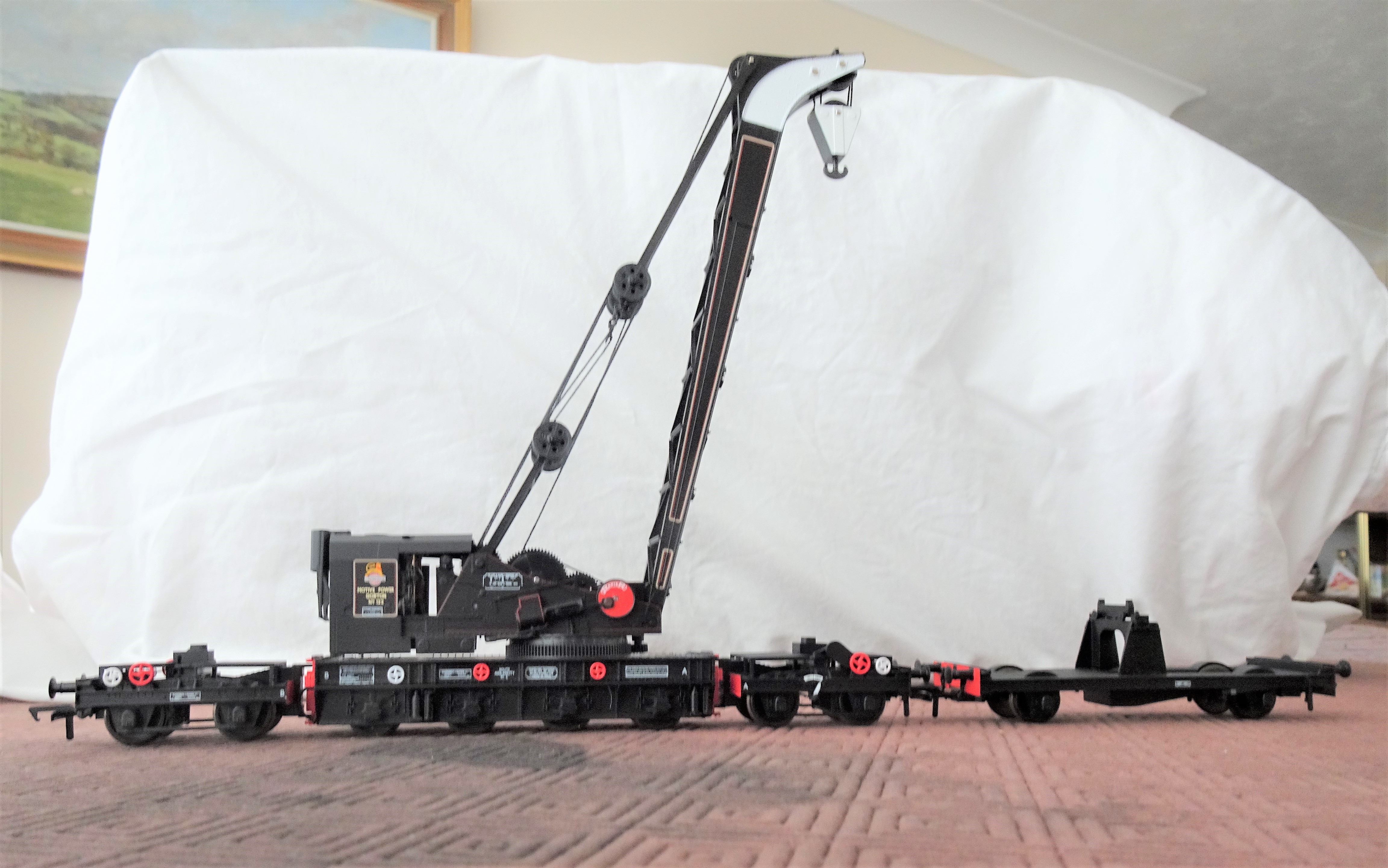
A Ransome & Rapier Crane
Readers of this blog will recall that my father has a significant interest in breakdown cranes; he has published a series of books on them and is the honoury president of the Breakdown Crane Association. As a result of this, a few years ago, he took a call from Bachmann when they started to research the possibility of filling a gap in the ready to run scene for a accurate breakdown crane. He delighted in being sworn to secrecy on this until the model was announced and now, some five years later, it has finally arrived on the shelves.
So after a somewhat unsatisfactory retail experience with Rails of Sheffield (which I won’t be repeating, there are plenty of other retailers out there), an example of a Ransomes & Rapier 45 ton crane arrived not much more than a couple of hours spare so that it could be parcelled up in its Christmas wrapping for my father. Now that it has reemerged, it is time to take a look at it.
Prototype
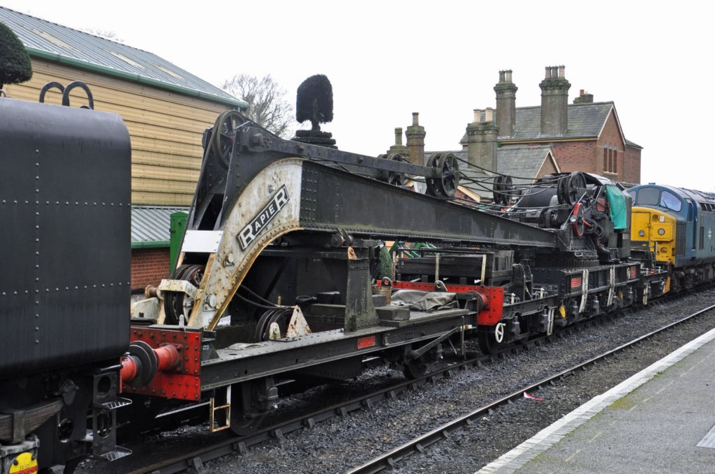
The prototypes originate from the early years of the last world war and were initiated by the British Government; in part in anticipation of a lot of emergency repairs being required following enemy action and also for use on the continent once a toehold had been achieved. Initially a total of six were made, going to the SR and GWR but subsequently a further order of nine were made, mostly for the military but with a couple for the LNER and another for the SR. The example I bought being from the latter batch, being initially based in Gorton on the ex GCR system.
There were detail differences, with many of the railway company vehicles utilising standard components from their eventual owners. The valve chests for the cylinders moved to the exterior in the later batches and the operation of the loading of the relieving bogies became hydraulic latterly. The biggest changes, however, related to the match wagons where there was both variety of arrangements of tool boxes at the time of building and generations of modifications thereafter.
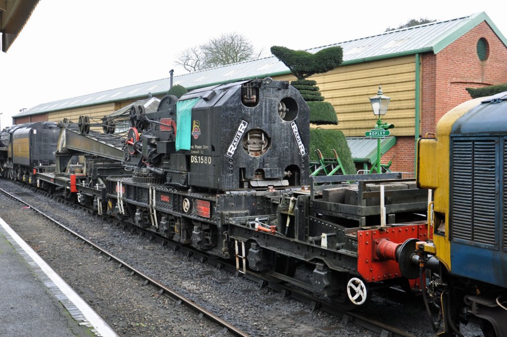
The cranes lasted until the mid 1980’s and a number of them survive in preservation, so if you want to see the real thing you might want to head to the Midhants Railway (on which the prototype photographs were taken and reproduced with kind permission of Carl Watson), the Bluebell Railway, the Great Central Railway, the North Yorkshire Moors Railway or the Swanage Railway. Below is a link to a video of the Midhants crane in action:
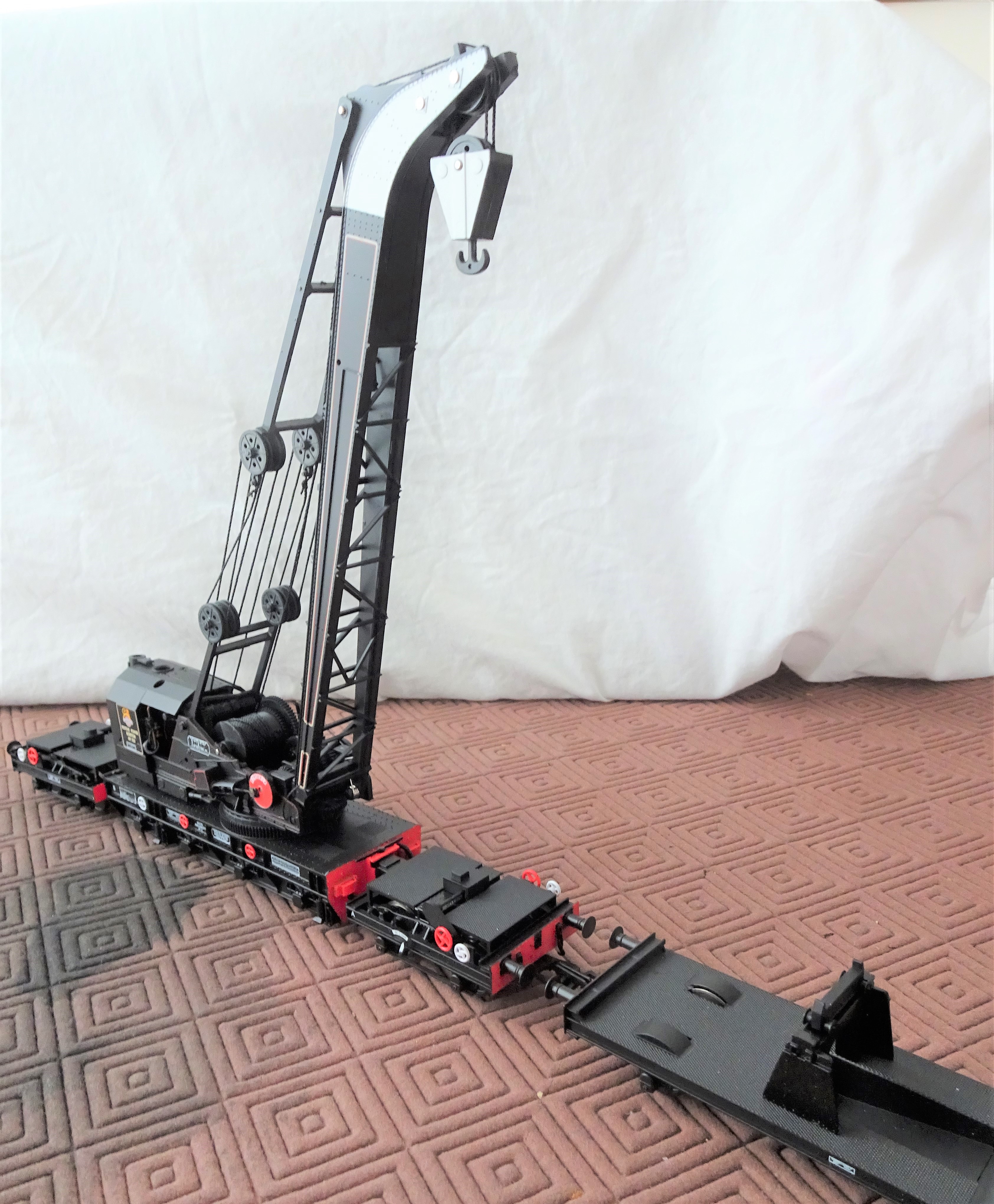
Model
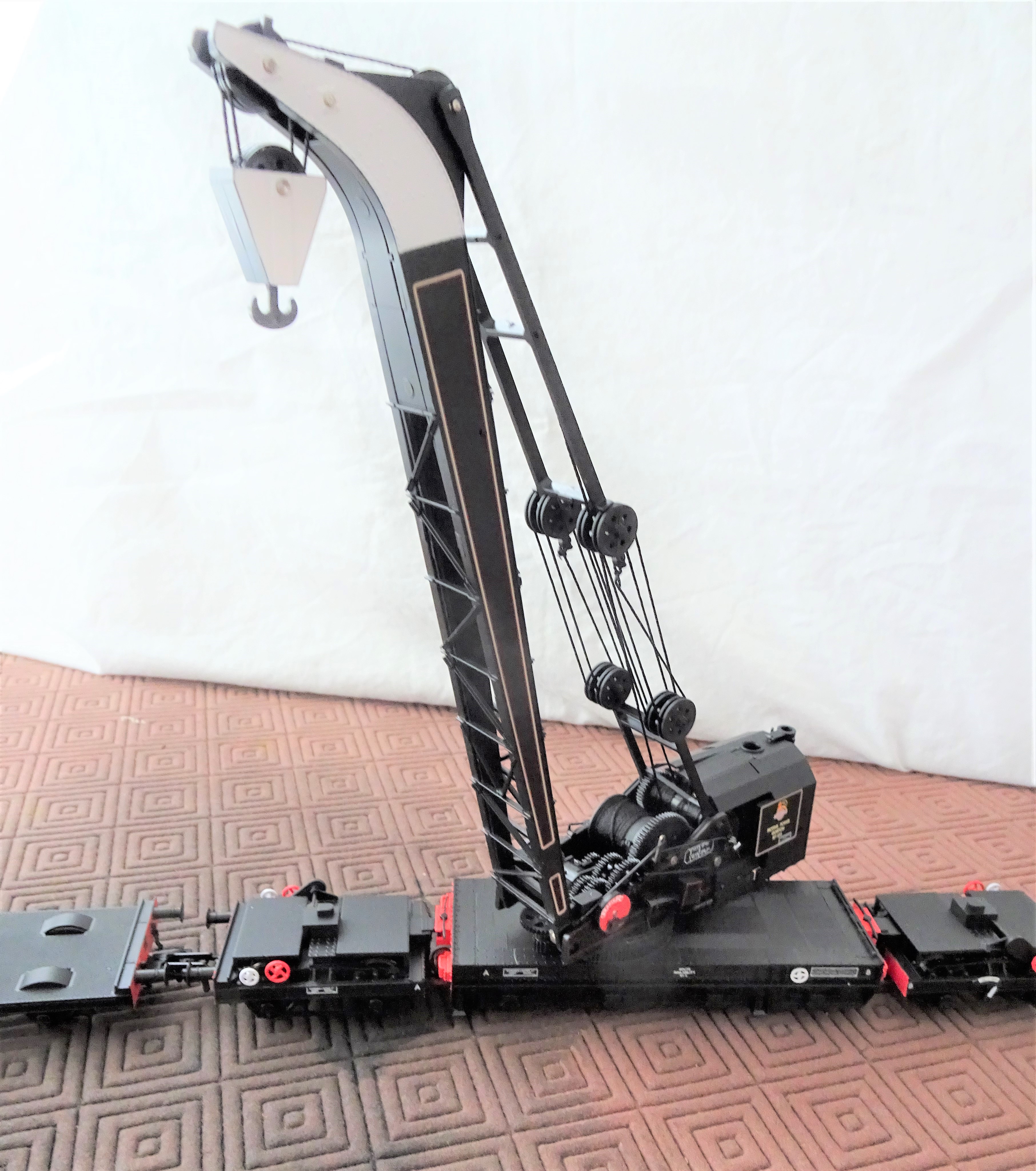
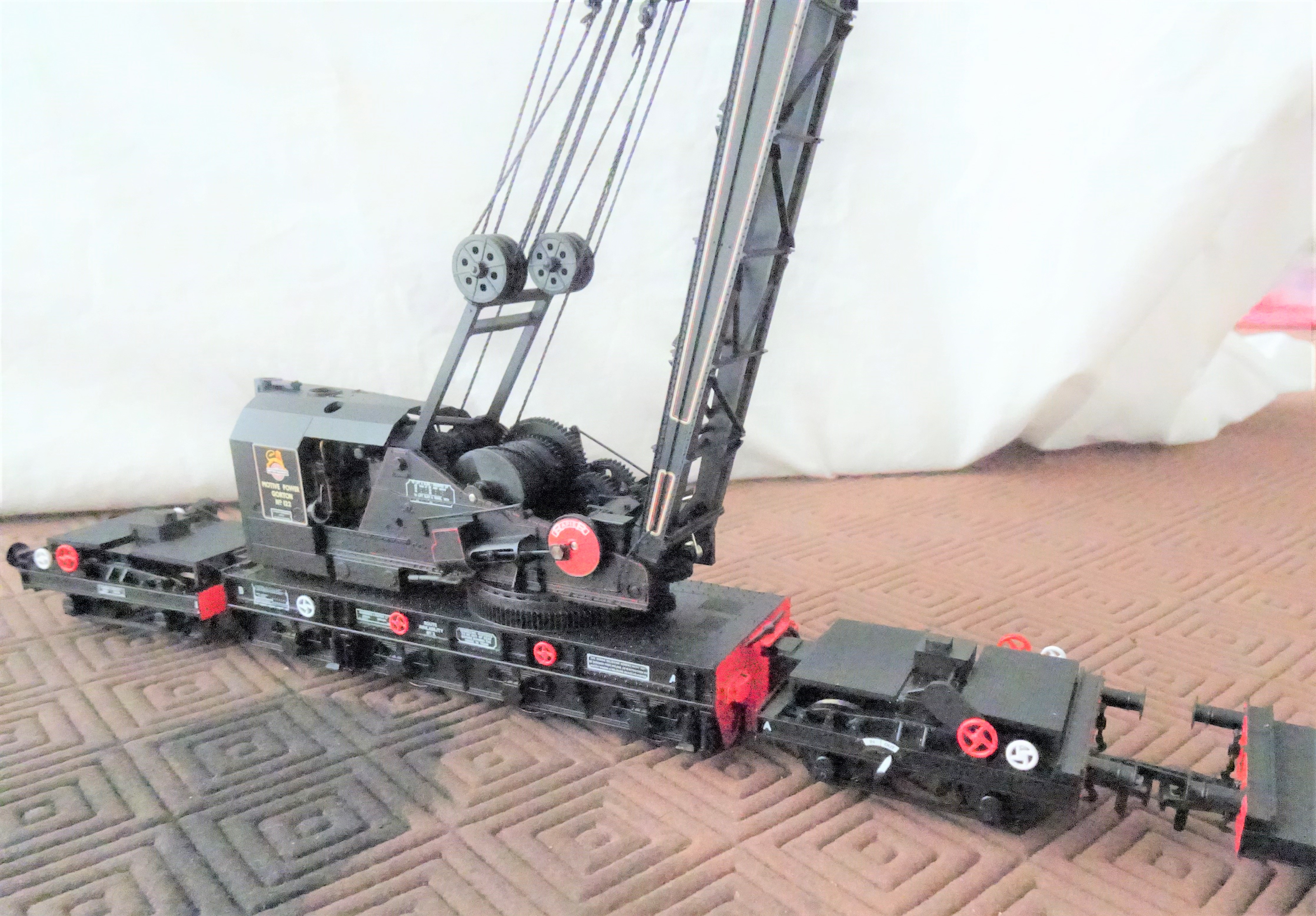
The first thing you notice with the model is that it is some way from the toy train end of the model train market. The prototype is smothered in detail; with the fine bracing between the sides of the jib, the gear trains, axleboxes and flywheels all being a bit out of the ordinary for the ready to run market. Bachmann have had a really good go at this and for the greater part they have got it right – very few could model a crane as well as this. There are, however, several compromises made to enable them to be operable. This particularly shows at the bearing points at the head of the jib (exposed metal when they shouldn’t be visible) and on the crankpin nuts to the flywheels (way too big and hexagonal). I understand why this was done, but it sticks out to my eyes! Some touching in of paintwork will help (but not be perfect) and the replacement of nuts with something more subtle should be possible.
The detail is very delicate and the model needs to be handled very carefully as a result. Even the most careful (and I don’t count myself in this group) are unlikely to keep all the detail in place on any model that does not merely sit in the display cabinet. With a recommended retail price of £250, substantially more than any other product that is not filled with motors & electronics, it is doubtful that too many will end up in the hands of children – maybe that is just as well!
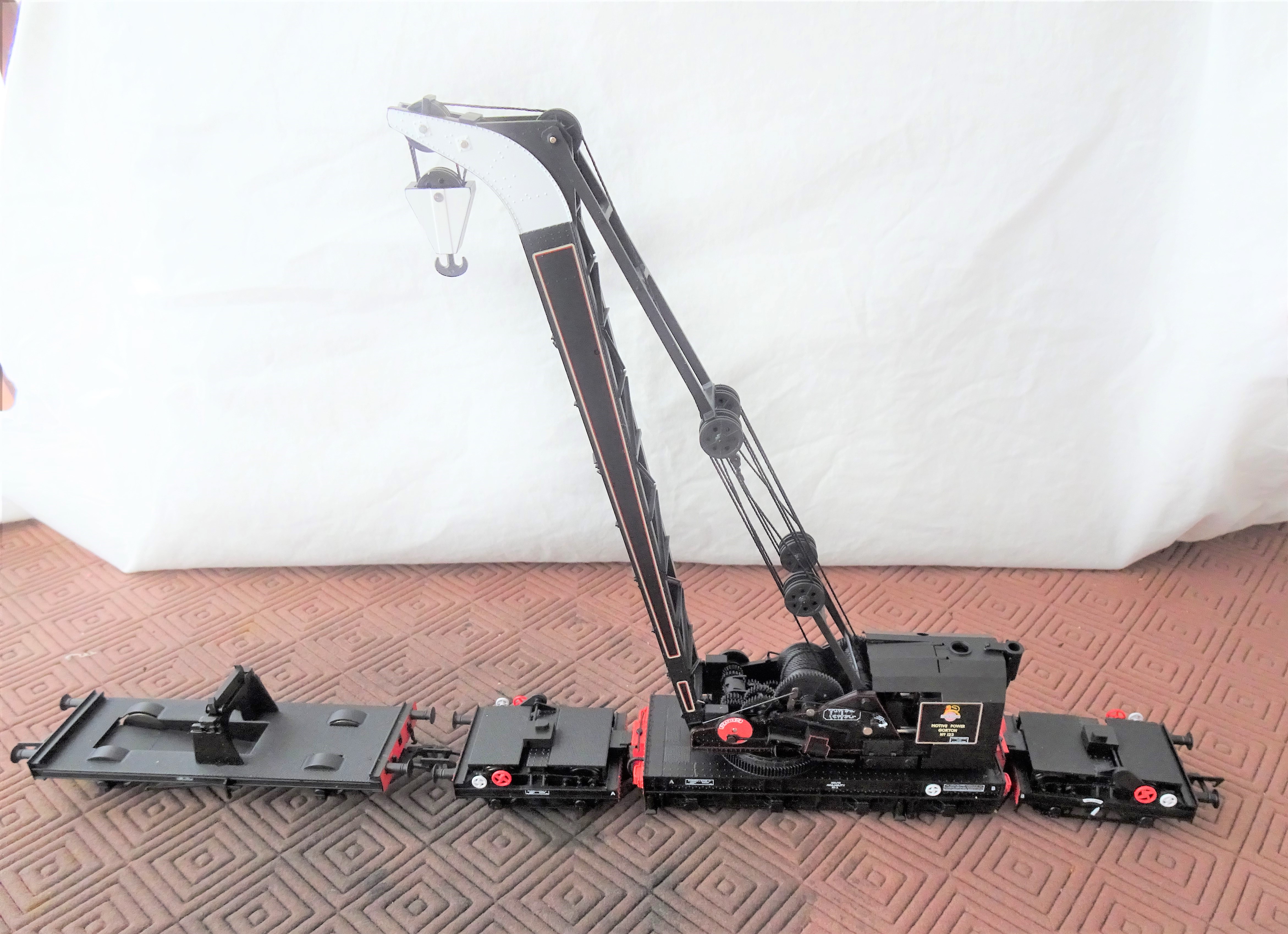
The model I bought, the early BR model in black – Bachmann ref SKU: 38-802, has a match truck without tool boxes. This is correct for the specific crane post the early 1950s but what is not is the missing insides to the splashers. This seems to be a compromise to accommodate OO wheelsets without making the splashers excessively deep. It is easy enough to fill in the open spaces if you model in one of the wider gauges and it will make a big difference.
The painting and livery is particularly fine on the model. Even better there are some exquisitely delicate etched plates that can be applied on top of some of the plates. I suspect I see the shadow of Mr Hanson on them.
Options
It looks realistic to get P4 wheels into the crane underframe and definitely so for the runners/match wagon. I would, however, be concerned as to whether a four axle vehicle could survive all but perfect track in P4 and how many of us have that? I suspect that it will all be very tight too, so some pretty large radius curves would be needed if a P4 model can get around them. Of course I will have a go, but it is not high on the to do list at the moment!
I think it is only a matter of time before someone looks at trying to motorise the crane. I think I will say good luck to them! Getting micromotors in might be possible for at least movement along the track but that still leaves slewing of the crane deck, raising of the jib and raising of the hook to go – getting another three in looks pretty difficult to me! The model does include internal hand operated mechanisms for the latter two movements – there are access panels that pop out to reveal a socket to receive a hand wheel. Thus, it is realistic to stage scenes, but not (in my eyes anyway – I really do look forward to someone having a go!) to make a fully operating model.
What is a must though is to add the paraphernalia of clutter the real cranes acquired in operation. Photographs show that they typically attracted lumber sections, jacks, chains and tarpaulins as if they were magnets. Cranes, not being front line stock in the public eye, tended not to suffer repaints very frequently and as they stood outside, they did weather and pick up corrosion spots. So any self respecting modeller needs to do something about how clean they look.
Although there is a very long in the tooth model crane from Hornby, it is somewhat of an uncomfortable marriage of several different cranes (the really old Hornby Doublo diecast version is better but quite crude), so does not cut the mustard. There are a limited number of kits for other cranes – notably the D&S Models Cowen Sheldon 15 ton breakdown crane (an example of one might grace these pages eventually!) but these are full on kits. Thus Bachmanns cranes are not only attractive models in their own right but they have a field fairly clear of competitors.
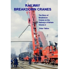
If you want the book on the prototype you need volume 2 of my father’s book – at present it is out of print but it is hoped with a bit of pressure on the publishers, Crecy, they can be persuaded to do a further print run.
The Bachmann crane is presently available in an SR livery, a GWR livery and then a pair of BR liveries – the 1950s livery shown above and a later gulf red livery. An example of the latter is below: