Blog Archives

Boards Back Home
Just prior to Portchullin’s last two exhibitions, Tim of S&T Joinery brought around the last couple of boards so that all of the scenic boards are now back at home. Obviously, this meant that we had to do a test erection!
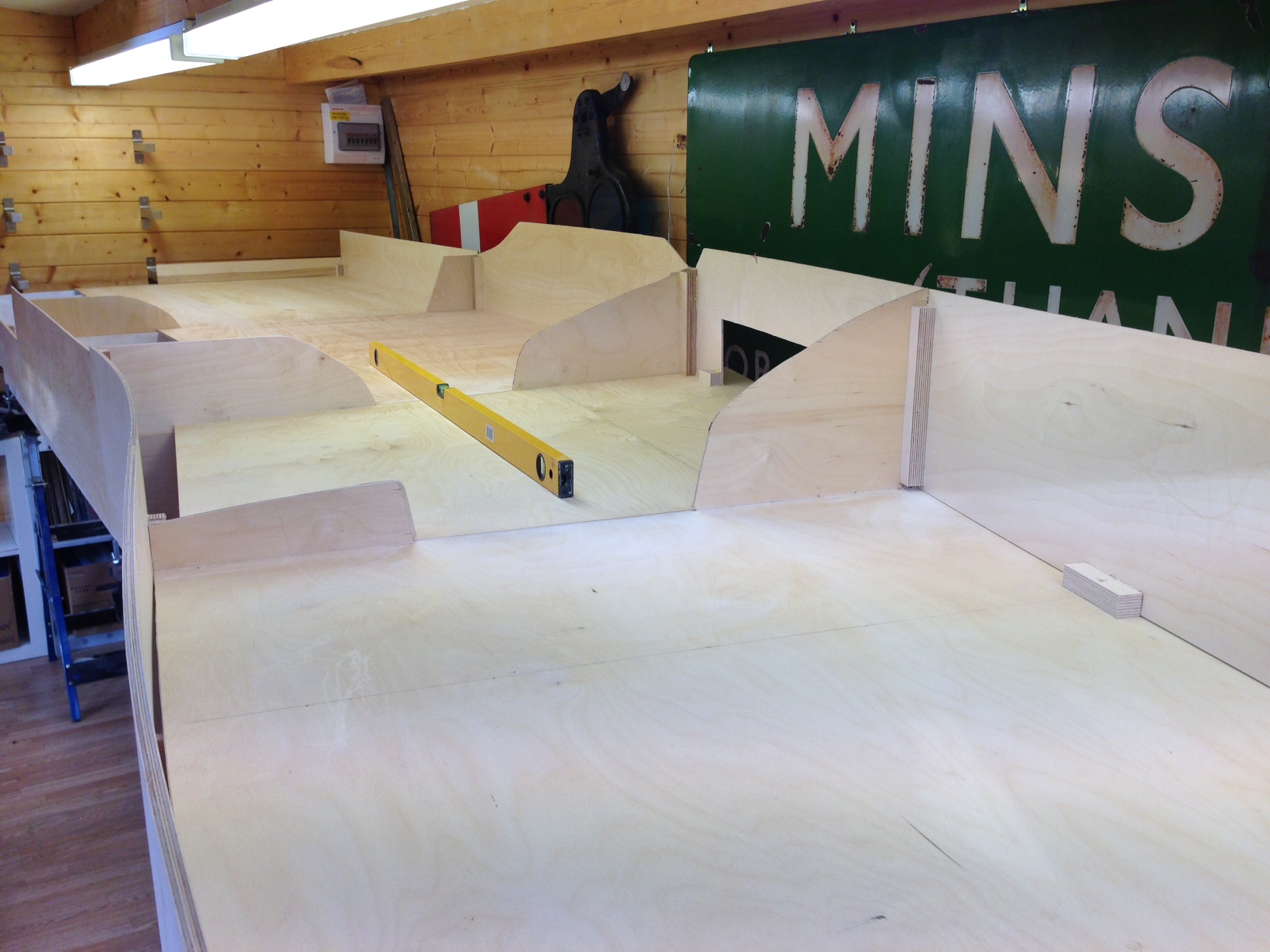
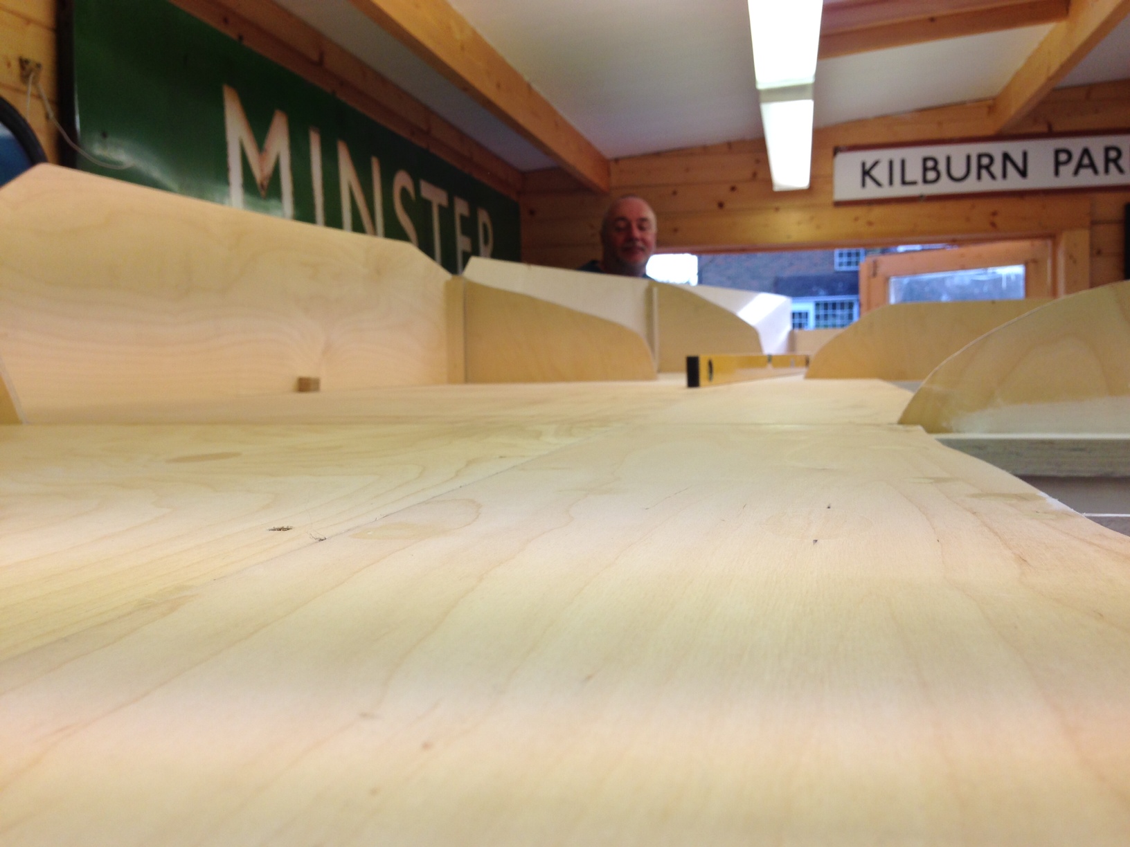
And very pleased I am too, especially with how flat they are. A rear contrast to the rolling hills affect that I managed on Portchullin. I am obviously hoping that this is going to result in much better and more reliable running.
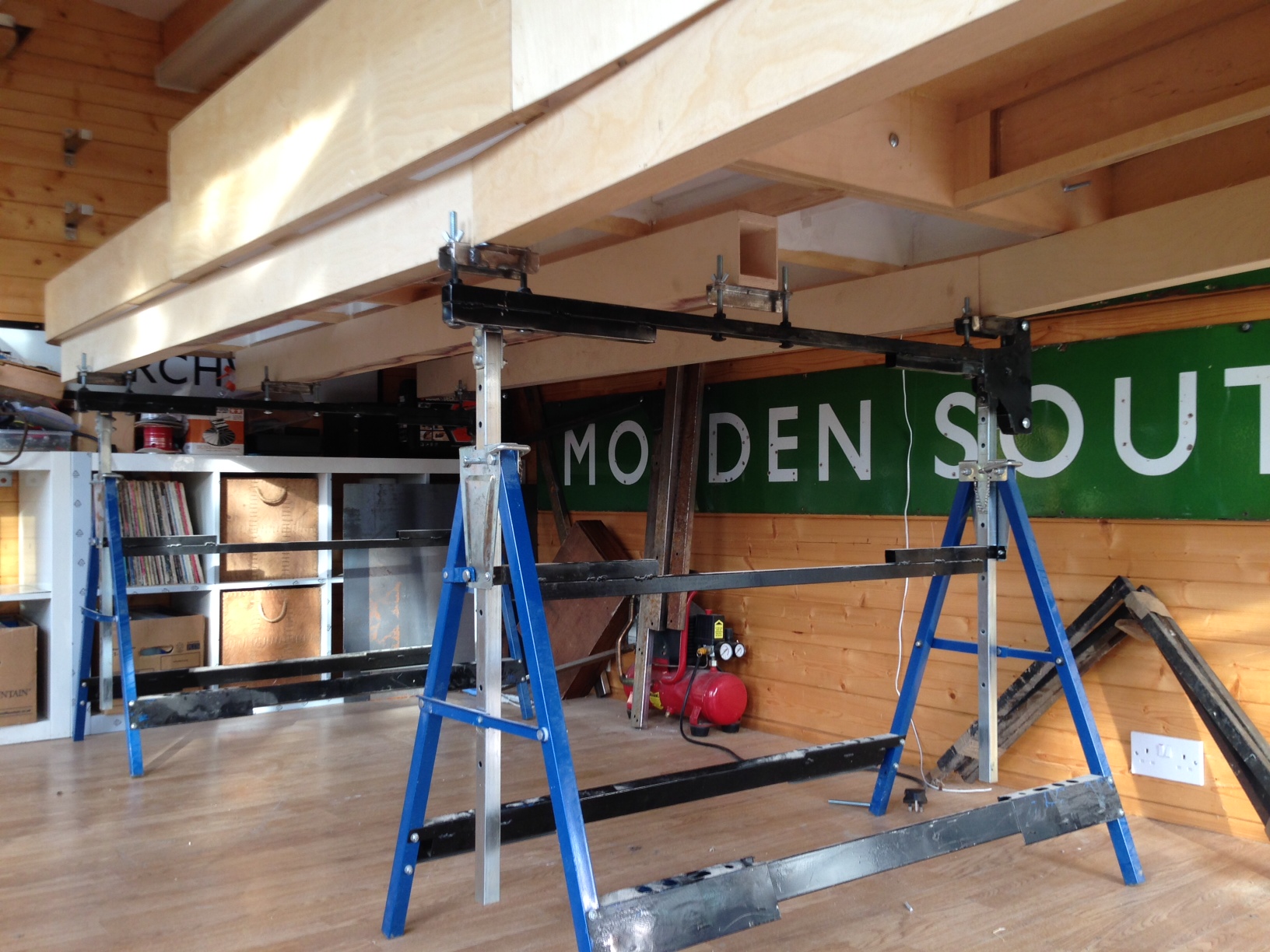
The design of the leg and the supporting beams can now be seen more clearly. it does take a bit of time to get these level (caused I believe by the absence of levelness in S&T’s workshops! However, once the beams were level, it was a matter of moments to place the boards on them and connect them up. So I think we will do some setting out at the weekend.
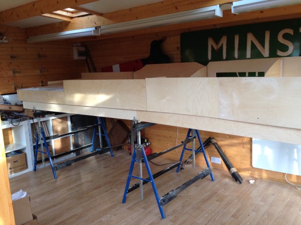
In some respects the photos don’t quite do justice to these boards and also how large they are collectively. The width in the top view is 1200mm and overall the length of the boards together is 5250mm. As will become apparent in future posts, I am going for the “railway in the landscape” feel and I don’t want it to fee cramped either.
And if anybody wants an electric loft ladder, this is where you go http://www.st-joinery.co.uk/

Scrap Tank Test Build 5 – Getting on with the Chassis
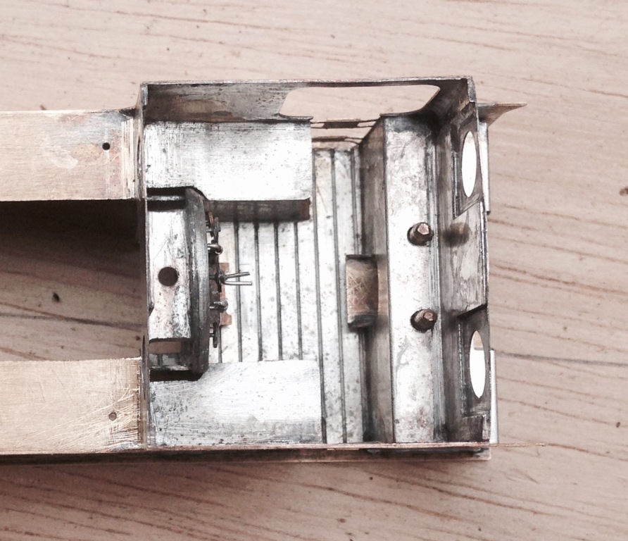
With the basic chassis made, it is essential to fit the nuts to secure the body to the chassis as both of these will be concealed with later work. So a quick test fit looks like this and we can get onto the next bit, the coupling rods. 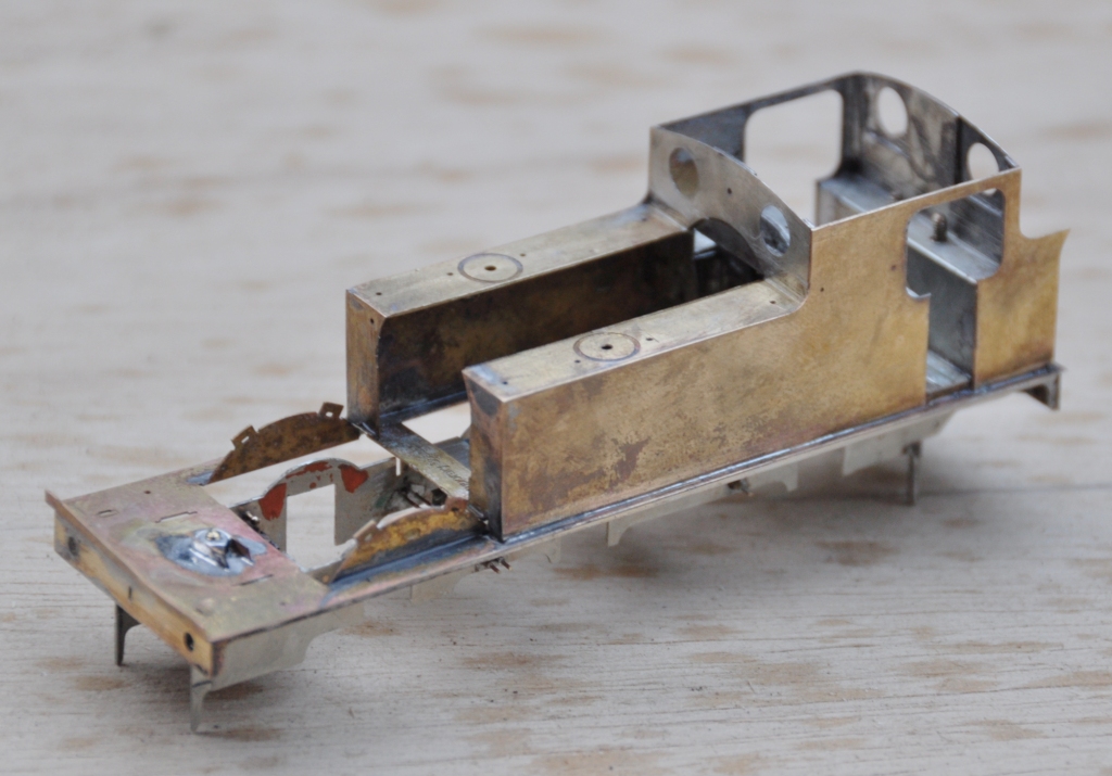
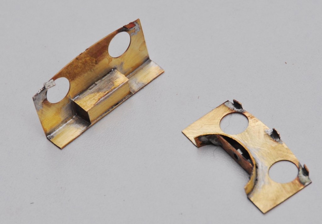
As is not uncommon, these are made from a pair of layers of brass laminated together. You can see that the outer layer is half etched for much of its length, with the full depth only being present at the bosses. I have also sought to make it easier to build these by including them in a folding jig – the folding is underway in the bottom portion of the view. The logic of the jig, indeed the whole kit, is to make a really smoothly running chassis much easier to make. Modern CAD and computer operated phototool creation techniques by the etchers means that it is possible to easily draw and then etch such that each dimension is faithfully repeated on the product. Thus, it is possible to be confident that the wheelbase will be repeated exactly on each side of the frames and also on the coupling rods. However, this accuracy is completely lost if the user has to laminate the two parts together by hand; it is not possible to get them superimposed on each other exactly or repetitively so the spacings of the crankpin holes will change. The jig overcomes this as the fold line is so long that there can not be any twist as it folds, so the two parts will meet consistently and accurately. 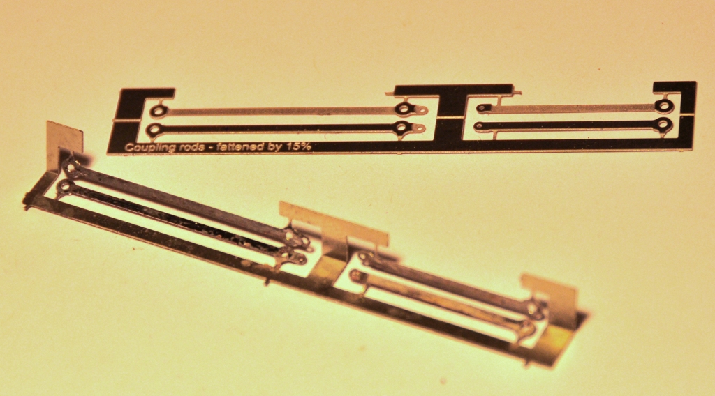
It is true that there remain two areas of variability. The first is that the degree of etching will not be exact on every occasion so the holes will be slightly bigger or smaller on each occasion. This can be easily overcome by making all critical holes a tiny bit too small and then opening the holes up with a ream (not a file, reams will open up a hole consistently). The second problem is that a fold is not always consistent on a fold line so the jig can protect against twisting but might not necessarily put the two laminates directly on top of each other. However, the important point is is that they will be correct horizontally, any error can only crop up vertically. Thus, when the crankpin whole is opened up, it is possible that it will move vertically slightly but this will not change the dimension between the holes so the critical dimensions should be retained perfectly.
The above is all true in theory but in practise there was an almighty cock up in my artwork; so I was deprived of finding out. A total case of designer error and when this is yourself, there is no one else to blame………………. 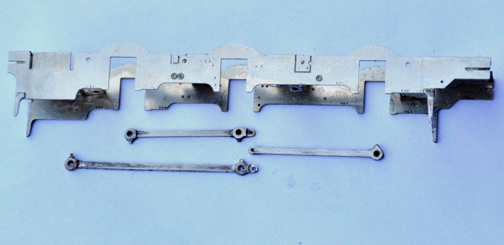
………..I made one of the coupling rods no less than 8mm too long – doh! I have no idea how, but it needed chopping; so it was back to the old fashioned way of making coupling rods despite my high ideals! Fortunately, as they were laminated, it is possible to stagger the cut to make the splice – essentially the same technique as Alan Gibson’s variable length coupling rods. Anyway, after the cutting and splicing, I did get a sweetly running chassis and this is what it looks like. The unusually large wheels for a shunting loco are already making their presence felt! 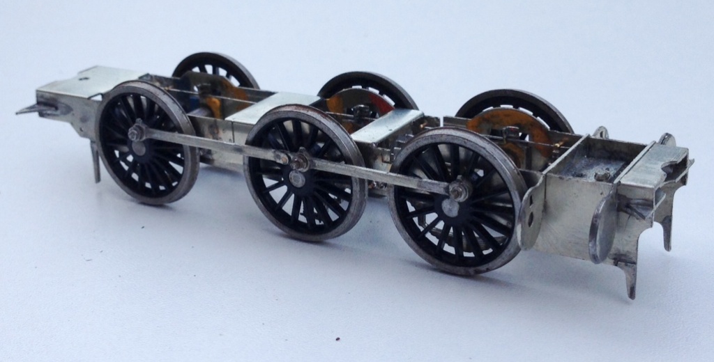
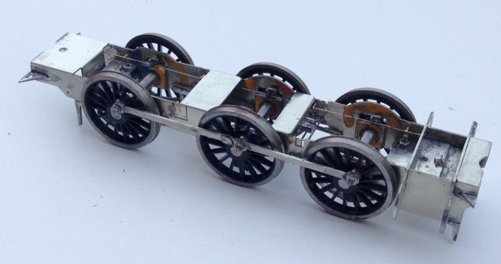
The chassis is created around CSB’s; continuous springy beams. A spring wire is anchored to the chassis at four points per side (for an 0-6-0) and at the centre of each hornblock. Thus each hornblock is supported on either side and can “bounce” on the spring. However, the clever thing about CSBs is that when a hornblock is depressed, not only does the spring wire flex a bit as suspension, but it also rocks on the anchors so the adjacent wheels push downwards a bit to equalise out some of the deflection. It produces a really smooth chassis and, if it is conceived at the design stage, I think is actually rather easier to both design and build than traditional compensation. This is a close up of a pair of hornblocks and a pair of the anchor points (the other is hiding behind the frame spacer on the right). Also worthy of note is the colour coding of the hornblocks; to enable them to be reinstated in the same hornguide each time. This is probably unnecessary with modern (and therefore consistent) hornblocks and the accuracy of the etching I have noted but old habits die hard! 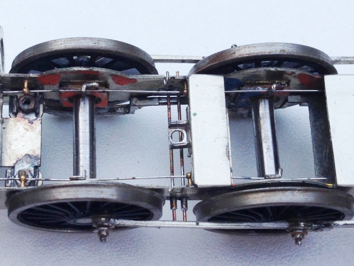
Scrap Tank Test Build – Part 3; Cab Inner & Roof
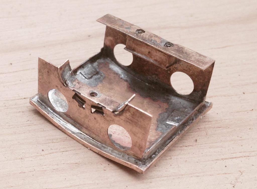
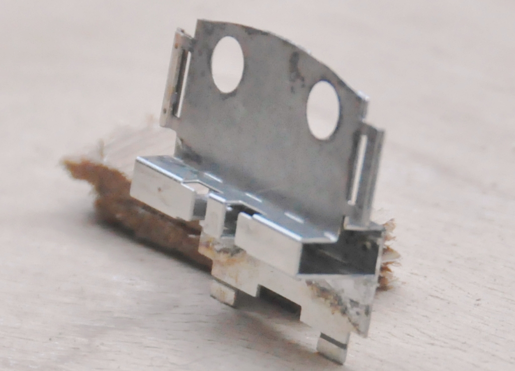
I have designed the cab roof and much of the cab interior to be a separate assembly, that can be secured by a series of screws. As can be seen below, there are two screws at the rear that locate into a tool box that sits on where the bunker projects into the rear of the cab. As the screws are somewhat lost in the bunker, I have come up with a little dodge where these are retained by an initial nut that traps them in place but still allows them to twist and thus engage in the cab roof assembly. The other screw comes through the top of the boiler, just inside the backhead.
The roof is connected to these fixing points with some inner liners to the cabs which can be seen here; the nuts for the rear piece are hidden in the toolbox and to the front within the false top to the boiler. You can just rebate in the rear spectacle plate that will take the glazing material.
The actual cab roof has a double skin, to aid its strength, include the lamp irons and also to assist with locating it on the cab. The outer skin includes the ribs that appear on the real roof, including a grove to allow brass wire to be used to form the seam to this. To the perimeter of this, there is a valance.
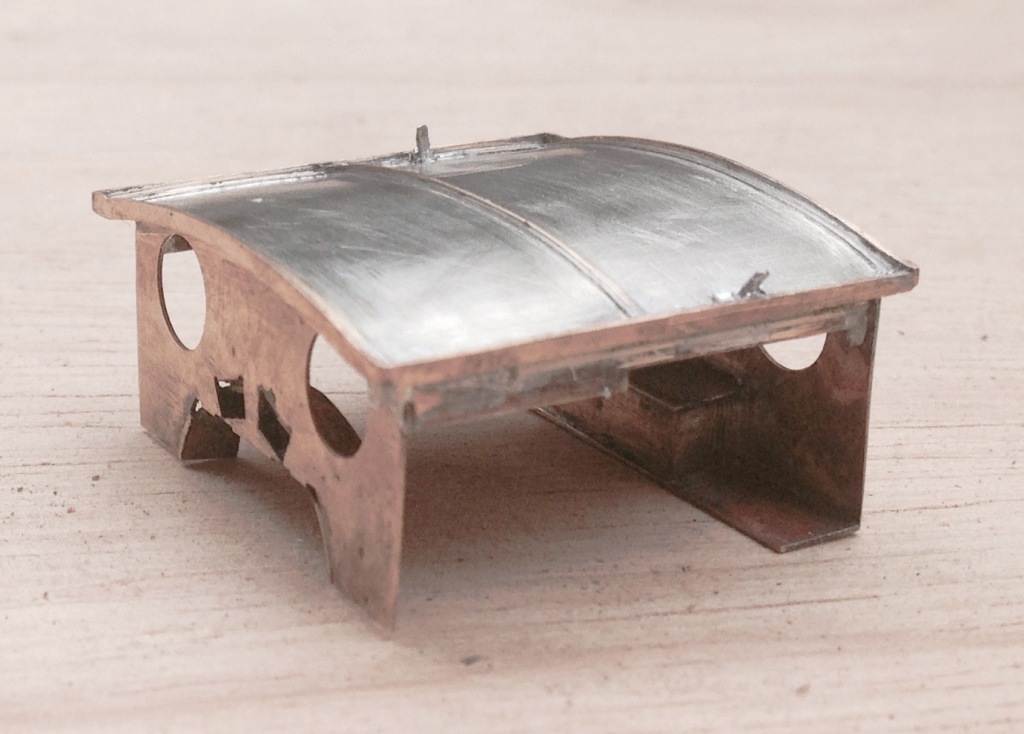
And this is what it looks like on. I find that I just can’t make roofs sufficiently well to sit perfectly on the body and nothing shouts “its a model” more than gaps where there shouldn’t be any – be this under buildings, roofs or between parts that have to be joined to structurally stand up! This is my solution, which I have used on other builds that I have done but it is so much easier when it is designed in.
Scrap Tank Test Build – Part 2; Continuing with the Body
The next stages of the test build were to do the footplate/tank sides/can exterior.
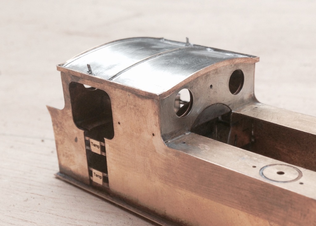
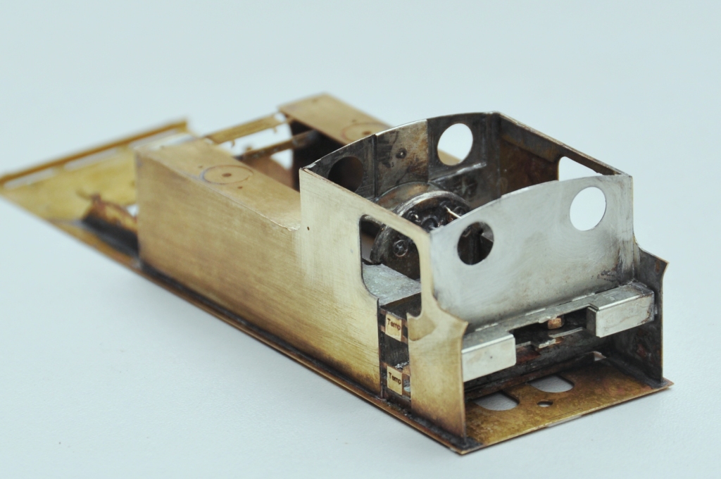
My initial design for the footplate is not particularly radical, but the test build has shown up that until the boiler is put in place (which comes some way into the build process) the front is somewhat delicate, irrespective of whether the footplate valences are fitted or not. Thus, in addition to the temporary stiffener that can be seen to the front of the footplate in the picture below, stiffeners will be provided to the front half of the footplates. The idea of these can be seen in the following view which shows the rear of the cab. By folding these over at 90o during the build, they give strength to the more delicate parts of components. Some will be incorporated into the finished article, others will simply be discarded when their job is done.
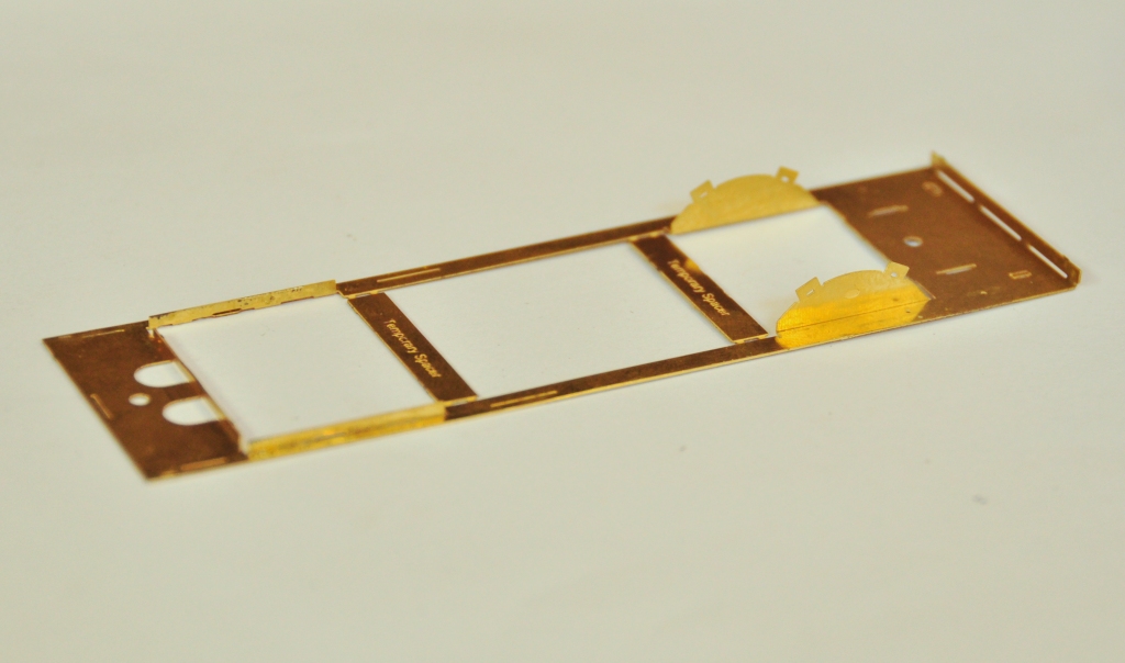
The two tanks, along with the sides to the cab/bunker, are conceived as a single piece (if you go back to my previous posting, you can see this in the flat in the etch). The two halves are separated by temporary spacers to both assist in locating them but also to give strength to the assembly prior to the fitting of the boiler which is where it will get its strength from. It was when I tackled this part, I reached the first disaster – the etchers had failed to half etch from behind so I was missing some fold lines. This was pretty frustrating as it entirely negated the intended efficiency of the design and even though I now have a corrected etch, I had to solder on by cutting the parts at the intended line of the half etch and soldering them together in the more traditional manner – exactly what my design was intended to avoid. As a result of this, there are no neat photos of the tanks being folded up and secured in place, we have to jump on a bit to see this.
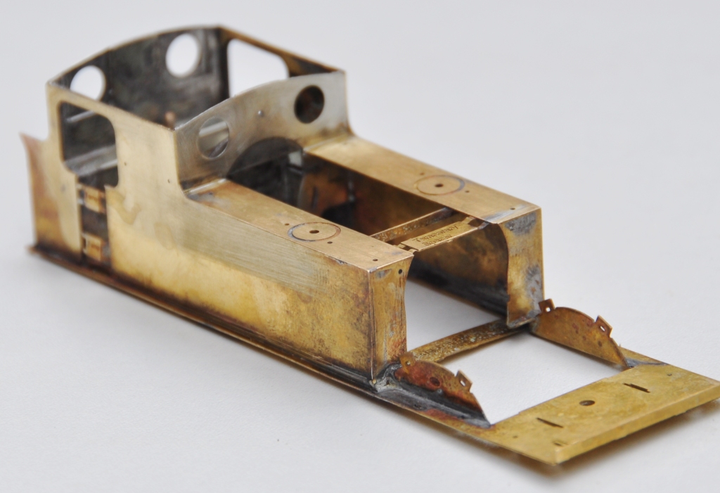
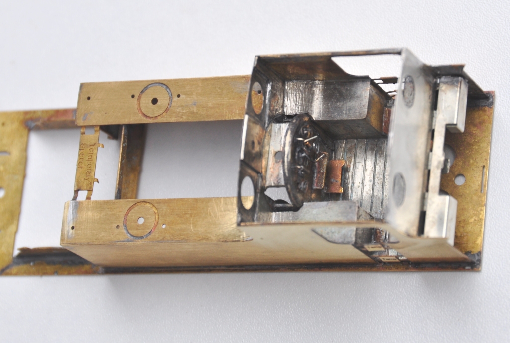
The cab fronts that were constructed earlier were no slid into place and I was pleased to find that it all fitted very snugly and in exactly the correct location. I did find that I could put in a further pair of fold up tabs on the running plate that meant that it was essentially impossible to put this in the wrong location, so this is another little refinement that will make its way into the production batch.
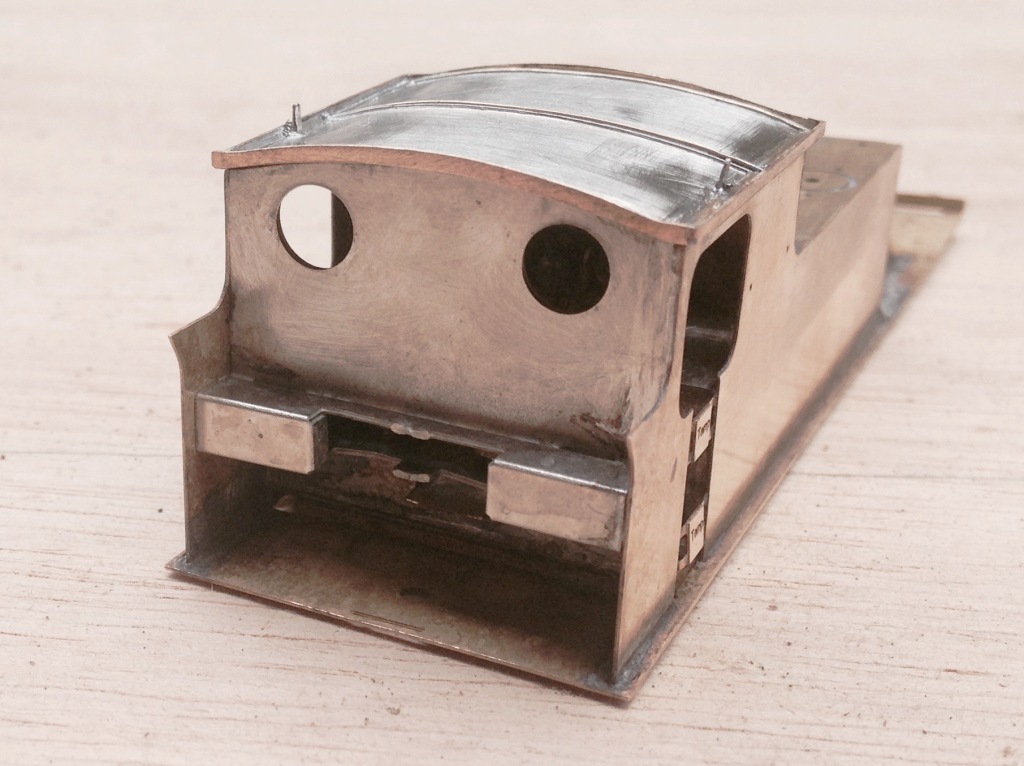
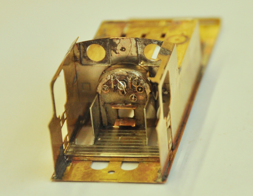
The rear of the cab was a similar fold up unit to that to the front, which was pretty easy to build but did have one dimensional error at its base that needed cutting away – well that is the purpose of a test build! All of this, has been created from one piece in maybe three minutes!
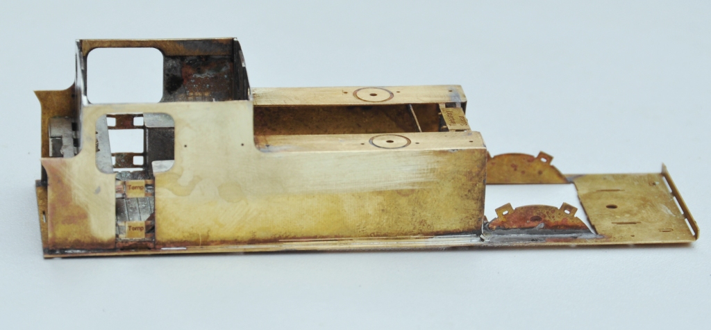
And this is what it looks like with the cab rear in place. If you look carefully, a couple of 12 BA screws are just visible in the cut out to the rear of the cab – the purpose of these will become apparent in a future posting but it is another one of my little ideas to make this easier to build/better when built.
And this is what the cab bow looks like from above, after the addition of the splasher tops and backs. One of the issues this illustrates is that this kit, as it stands, will only work for EM or P4 modellers. There is insufficient room to get the narrower gauge/wider wheel treads into the splashers.
Next up will be the cab roof………….
Christmas is the season for…………. jolly well finishing stuff off!
Over the break, I have been concentrating on trying to finish things. Like many people, I find it much easier to start a kit or project than it is to get it fully finished. Indeed, do we every truly finish our models – certainly not our layouts!
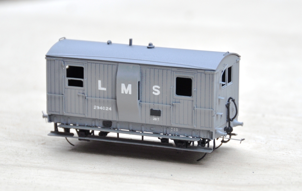
Back in March 2013, I completed a dia 39 goods break. These were the final Highland Railway break vans and it is not clear that they were actually finished prior to the end of the HR era. Given that I model in the mid 1920’s, I am quite content to do this in LMS grey which to date I have not seen the model depicted in! The main body painting has been completed and the van has been lettered but weathering, the interior and final detailing/glazing is still to be completed. Based on the Lochgorm Models kit with minimal adjustments (a few pipes below the chassis and sprung W irons in lieu of the compensation provided in the kit) this is what it presently looks like:
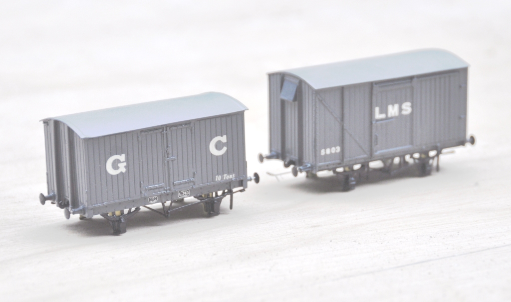
Also coming through the paint shops are a pair of vans. The first is a Great Central van build from a Mousa Models etched brass kit and the other is a LMS early standard van from an injection plastic moulded kit from Cambrian Models. Both are pretty simple models to build; the Mousa Models one was built as designed and no adjustments were found to be necessary. I only fitted springing to the Cambrian one and got rid of the rather too thick W irons in the process. Again the bulk of the painting is complete, but some dirtying work is definitely still required.
Apologies for the slightly squiffy photos; I left it a bit late in the day to take them and the light was poor. I have made a lot of progress painting the NER hoppers, but the photos of these really did not make it and need to be repeated. Something to post tomorrow I suspect!
Portchullin – Recommended Reading
Portchullin is in the press!
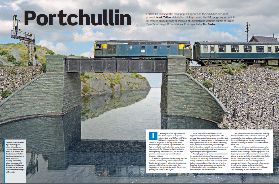
Rail Express have for many years included a modelling section to what is otherwise a prototype magazine. This year (and going forward in future years I beleive), they are producing a yearbook which is dedicated to only modelling features. Portchullin is the leading article with a series of photos from Tim Easter – and it is no less than 13 pages long.
Here is a taster and if you want to get a copy, it can be obtained here:
Chequebook Modelling – a Wee Ben
I don’t know whether this is a serious admission or not, but I have been doing some chequebook modelling – and my crime is rather more serious than the latest Hornby offering………………
………and it cost rather more than an offering from Margate too!
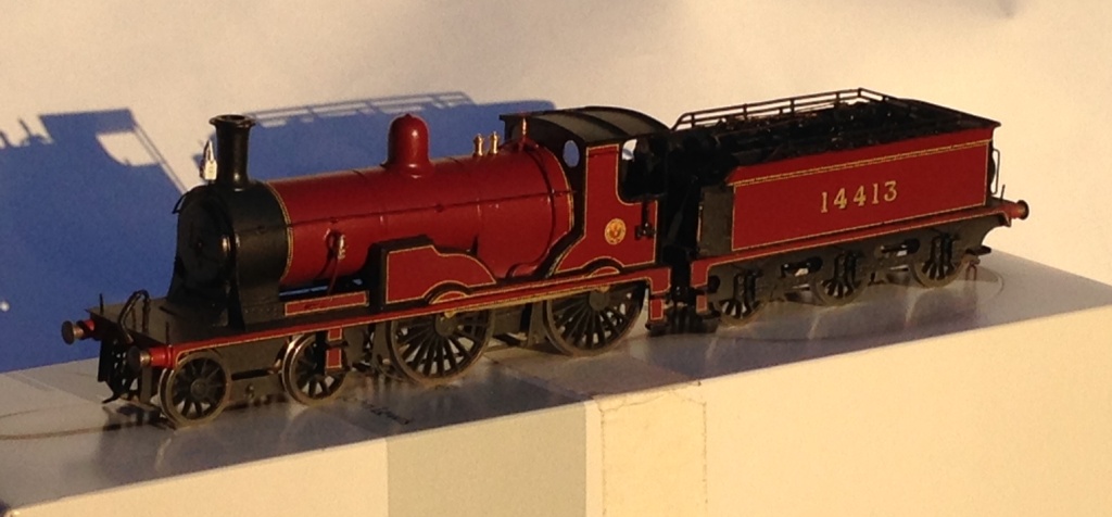
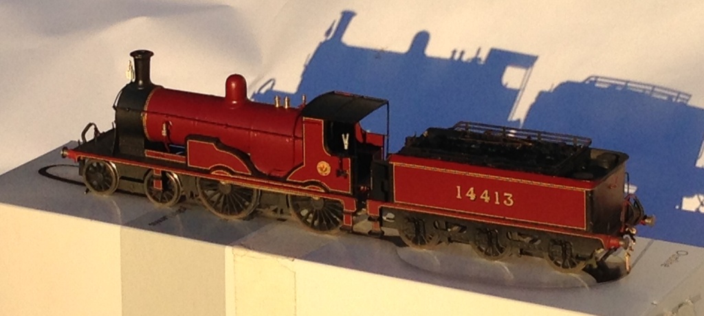
I commissioned John James to build this about two years ago (that is how long a pro builder’s waiting list is if they are any good) and this was delivered a couple of weeks ago. 14413; Ben Alligan – constructed as she was in the mid 1920’s so in the fully lined crimson lake and jolly fine she looks to I am sure you will agree.
But, there is a problem with her…………………..she has names. The LMS perpetuated nearly all of the Highland’s names that were still applied to the locos at the grouping (I can think of only one exception – Lochgorm) and continued to paint them on the splashers. We hunted around for a sensible letting and did not manage to find any where the font had the right serifs and slightly unusual massing of the down stroke of the leters, so John omitted the names of this and another that he built for my father (Ben Clebrig if that is of interest to you). That has meant that I have been fighting with CAD again and I think I have got close enough for my purposes (in 4mm, these are less than 2mm high!).
So once I have sorted out the right radius for the name (I think the Ben Slioch below is on a slightly too shallow an arc); then I will have a go at printing my own transfers. I have the appropriate paper, so lets see how we do!

One of the fun things with the Bens is choosing names for mountains that I really enjoyed climbing; Ben Alligan was probably around my 30th Munro and is a fabulous climb. If you do it, you have to do the full circuit and finish on the Horns of Alligan – a bit of a mild scramble, not as airy as Aonach Eagach (which I have done) or the Cuillin (which I have not!); but still a jolly fine climb. Oh and on a clear day you can see clearly to the outer Hebrides – fabulous in the blue sky.

The Horns of Alligan looking east.
Cutting the first Sod
Tomorrow should be a big day for Glenmutchkin, because if my brother remembers we will be cutting the first sod of the layout building.
Now all good railway lines start with a ceremonial cutting of the first sod by the Duchess of something or other; typically with a nice silver spade and after which everybody retires to the local hostelry for a fine dinner…………….whilst the navvies start the really hard work. Well we probably will only be different by dropping the silver spade.
More seriously, as long as he does not get blown away in the forecast storms, my brother will be bringing his welding kit over with him, so we can make a start on the big chunky bits.
Welding kit……………on a model railway; am I going crazy? You’ll have to come back to find out!
Brighton Road and Some Etch Masters
Less modelling has been achieved this week – due to a combination of work taking me a little more afield than normal and also because I was playing with someone else’s trainset.
In this case, the layout was Barry Luck’s (with assistance of the Mid-Sussex AG of the S4 Society) Brighton Road. It was shown in the carriage repair shop at Horsted Keynes; so we were serenaded by the sound of the real thing (and the occasional burble of a Sulzer as they had a class 33 working too.
Some rather nice photos from Jonathan Hughes are here:
and if you wish to see anymore; then go to here http://www.flickr.com/photos/nimbus20/sets/72157634415164752/
I was not totally idle otherwise, as I have had a bash at producing my own artwork for etching. I think this (it is a bracket for a signal a little like the one here https://highlandmiscellany.com/2013/02/03/first-signal-for-glenmutchkin/) is capable of being etched. I’ll be submitting it too Grange & Hodder soon to find out!
Whilst I appreciate that there are many that are now quite experienced etch designers, even if this started as a means to forward their own builds, I am still taking first steps in this direction so I am pretty proud of the above. Mind you, I might be counting chickens before…………….
The Road Overbridge – Part 1
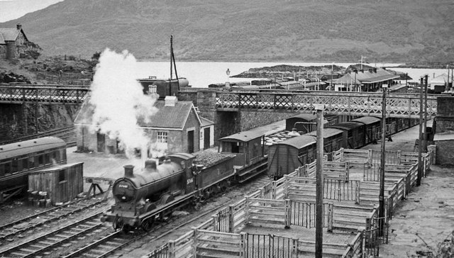
The bridge is in fact modelled on the one at Killiecrankie, but there were very similar ones at The Mound, Kyle of Lochalsh, Keith amongst others. Heres a picture of the Kyle one:
Copyright by Ben Brookshank and reproduced under a creative commons licence
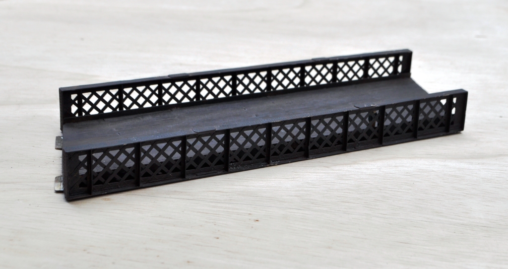
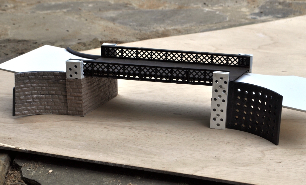
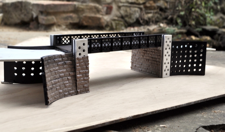
The advantage of using the Killiecrankie bridge is that I had previously modelled one for a layout of this station and whilst the abutments are still firmly attached to some mothballed boards, the deck could be reused. The deck has a nice skew to it to make it a bit more interesting and utilises lattice girders; which few seem to bother modelling. This is what it looks like:
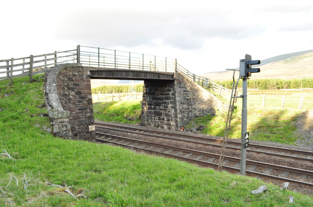
In terms of abutments, most Highland (and indeed this is common to most scottish lines) had bridges with curved wingwalls swept back from the face of the abutment. To give the layout some locational character, this was something I wished to produce. This is where we are at presently with the abutments: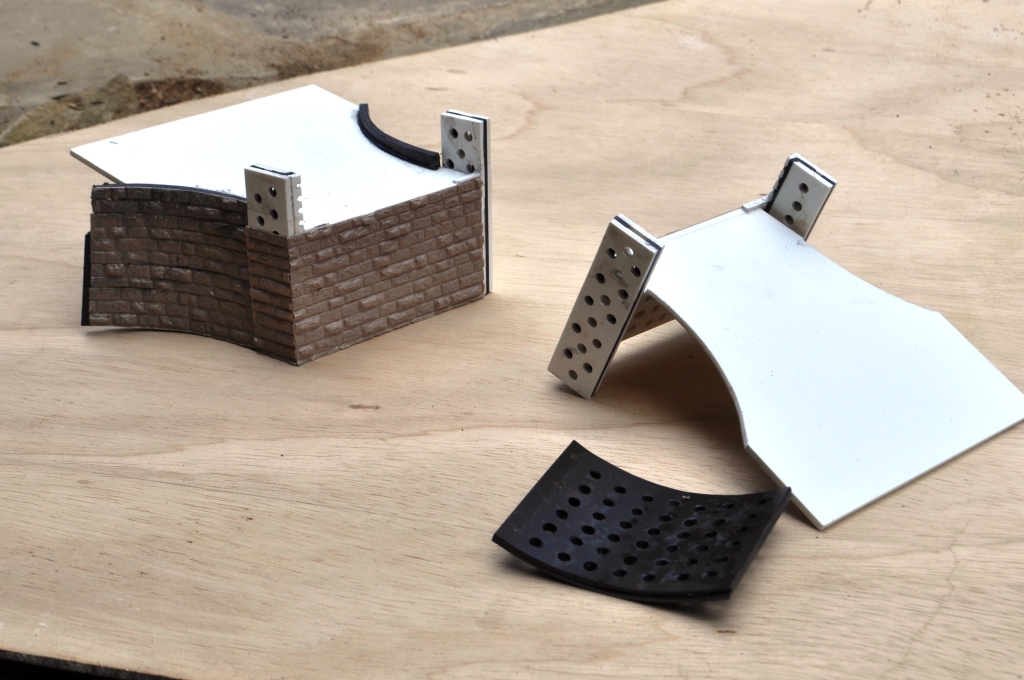 Typically, the random or dressed stone ranges from Wills are my favoured mediums but seeing Andy G making a good go utilising Slaters 7mm coursed stone I thought I would have an experiement with this. This is because many of the later bridges on the Highland used the same coarsely dressed stone; like this one at Dalwhinnie:
And these show the bridge deck on the abutments as they stand:
_________________ Mark Tatlow
