Normal Modelling Will Resume Soon…..
Sorry for the absence of any posts for rather a long time………..
We decided to move house, for a few reasons (a pleasant side effect of which is I can build myself a larger railway room) and this has been nearly all consuming for a few months. We are now moved and whilst we remain surrounded by boxes, normality is slowly returning to our life.
So some modelling posts soon, but first a summer holiday!

Back from the Paintshop
Some while ago, I showed a completed NER auto-trailer and mentioned that it was for the paintshop. Given that it was to go into full NER coaching livery I am pleased it was not my paintshop!
Well, it is now back and doesn’t it look fine…………..
The painting and lining has been done by Warren Haywood and as you can see there is little to fault about it. It now needs finishing with grab handles, buffer heads and glazing.
And that reminds me that I have another one in the box and they did tend to operate as pairs……….

A Fold of Cattle Wagons
Your pub quiz fact for the day is that the collective name for Highland cattle is not a herd, as it would be for most cattle. Instead, and only for Highland cattle, the collective name for a group of cattle is a fold. If that does come up in a pub quiz, you owe me a pint!
Cattle were an important part of the highland economy and hence were a good source of income of the Highland Railway. In my slightly distorted version of real history, there were 4 million head of cattle to transport per annum in the Glenmutchkin area (which is remarkable given the cattle population of the entire UK at the time was only a little bit higher!). Thus, a fold of cattle wagons was obviously a pre-requisite for Glenmutchkin and this is what I have been working on of late.
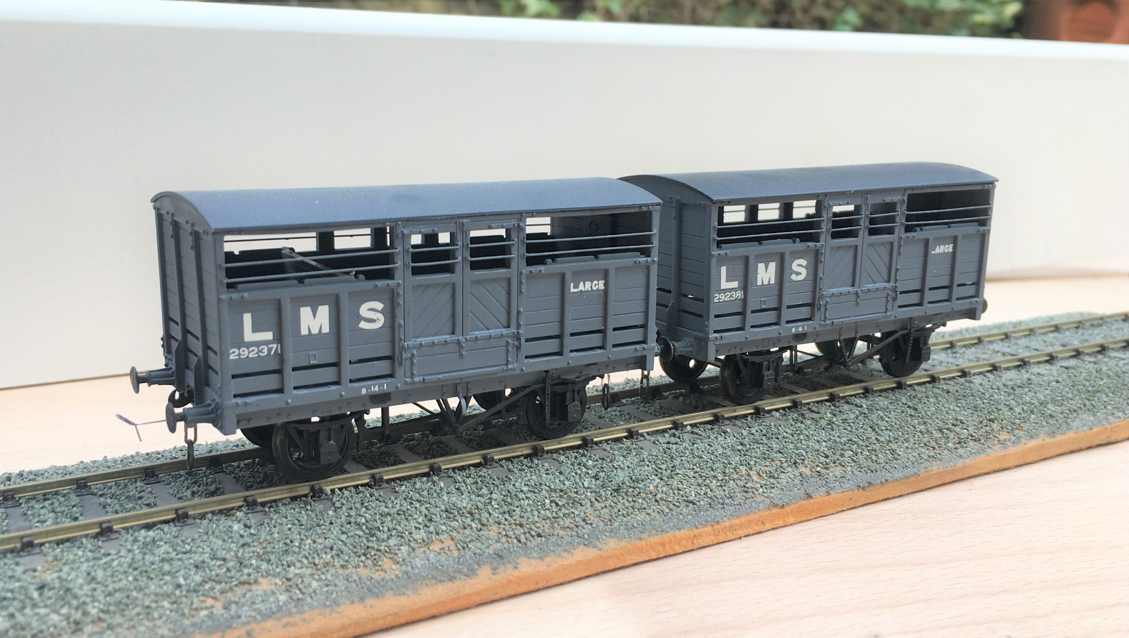
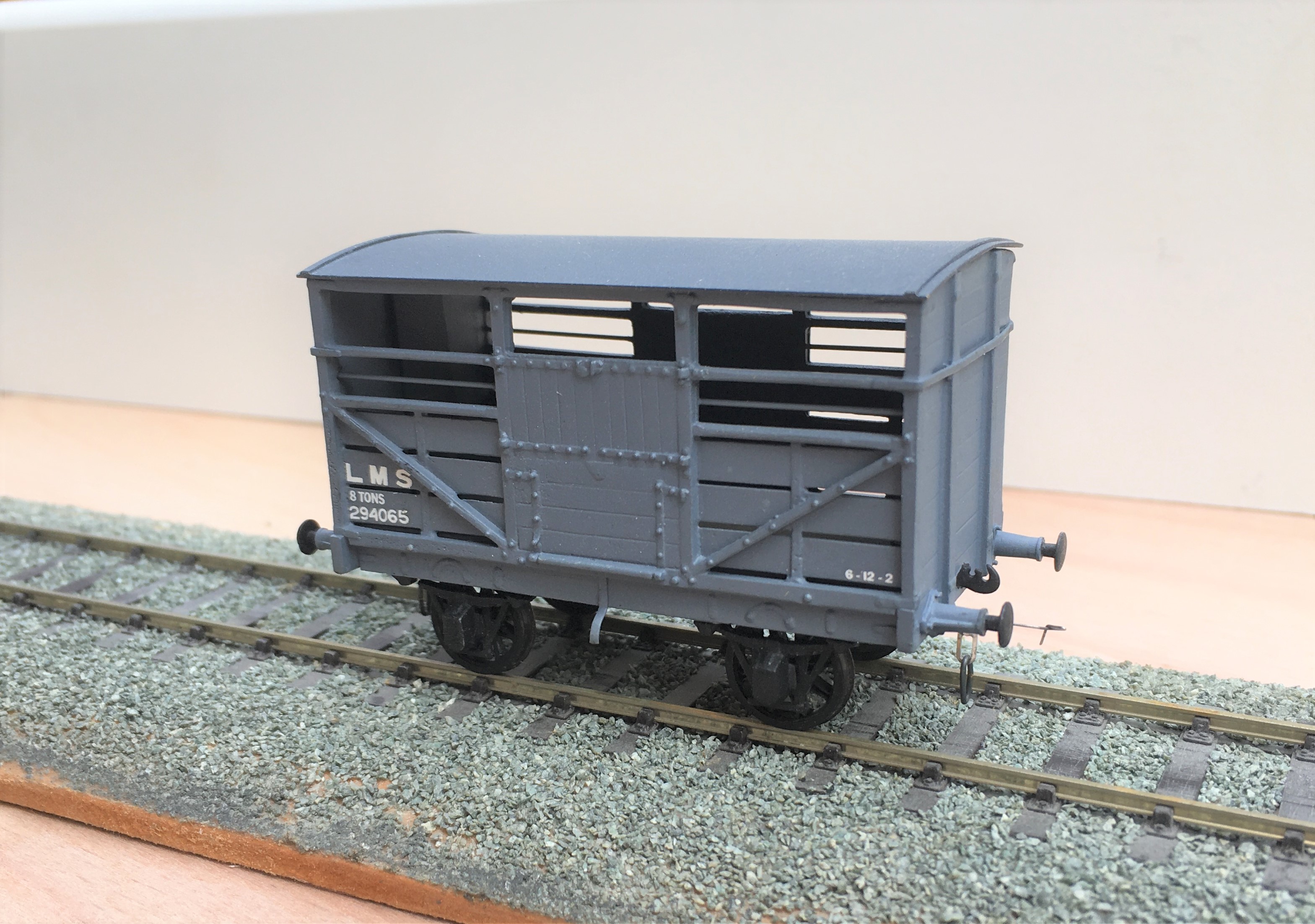
First up are a pair of LMS standard cattle wagons; to diagram 1661. These date from 1925; so they would have been fairly new at the time that my layout is set in. These were built from Parkside plastic kits with only moderate modifications around the break gear and, of course, some sprung w-irons. Being a relatively recent kit, it is generally very good and whilst it is possible to convert it to some alternative variants, these came later than my modelling period so I was not tempted. I am concerned that I have painted them rather to dark though, so I will be weathering them on the light side.
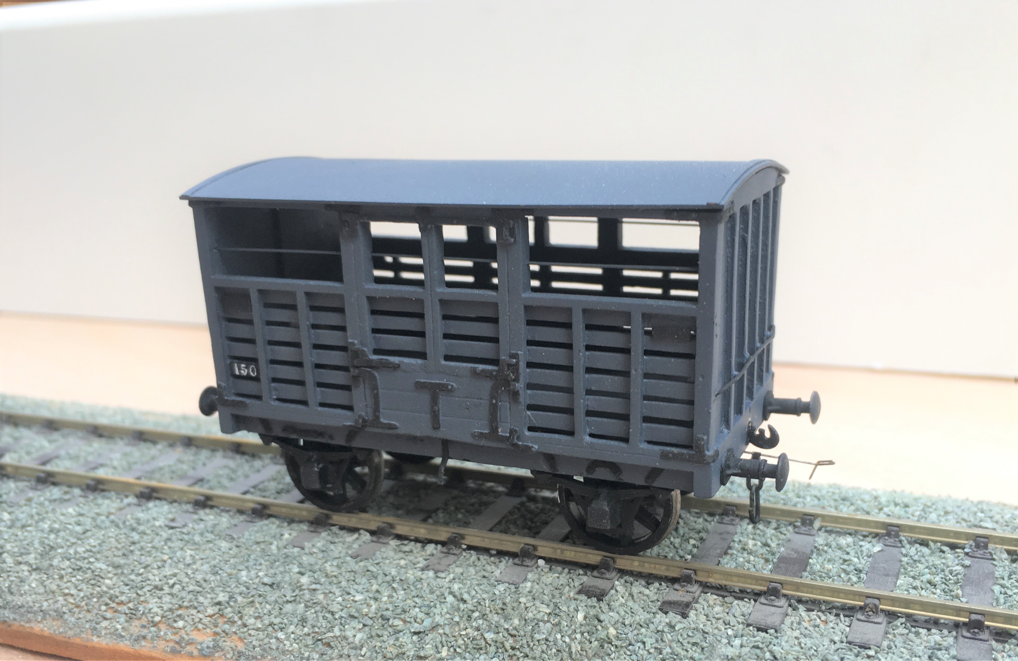
Next up is a Great North of Scotland Cattle wagon, from a Model Wagon Company white metal kit. This is a much older kit and didn’t it felt it! For reasons I am not certain of, the two sides were not the same length so in practise the body is a bit trapezoidal – but can you tell? The casting was also covered in flash which was a particular problem in the gaps between the wooden slats – this meant I spent a few hours I would sooner not have spent scraping it out to keep these clear. The GNoS vehicle was a much more basic vehicle and, strangely, did not get any large ownership lettering so they remained rather anonymous, Instead, they had simple cast plates, which I made from a locomotive number plate and dry brushed white on the letters. I have glossed over the fact it does not have the right number or even a consistent number from one side to the other – sod the “getting it all right” mantra!
I have also built a further Highland cattle wagon, built from a Model Wagon Company kit. This is the Drummond era version and I have already built a number of these so this was relatively routine – its just as well as there are still a couple in their packet waiting their turn!
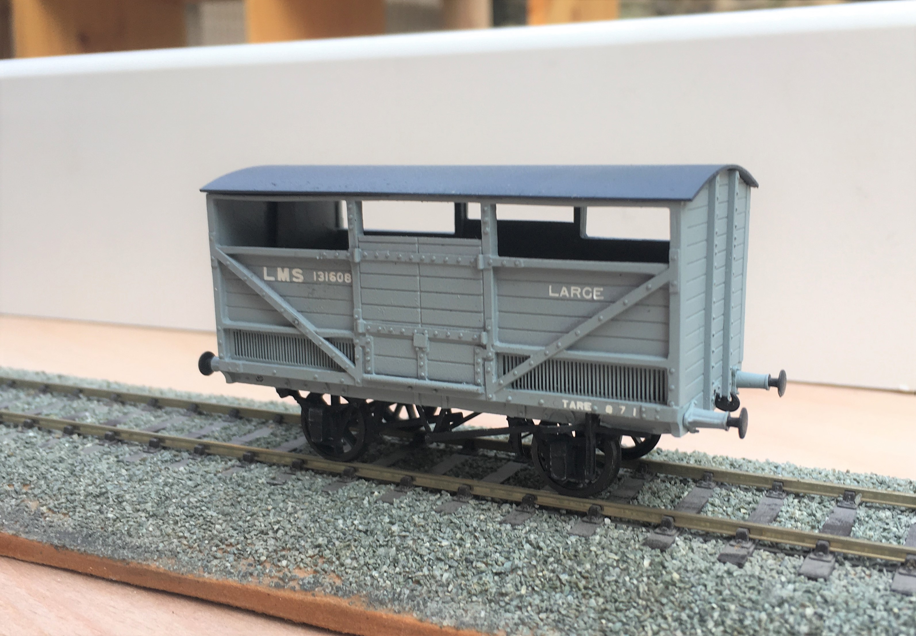
The final cattle van is a David Geen kit for the L&Y large cattle wagon. Whilst still a whitemetal kit, it is of somewhat better quality than both the Model Wagon Co kits so was rather easier to make. Even then, it did need filling at the corner joints and I felt the need to swap the brake levers for replacements – why to even the better manufacturers use the same material for all of their kits?
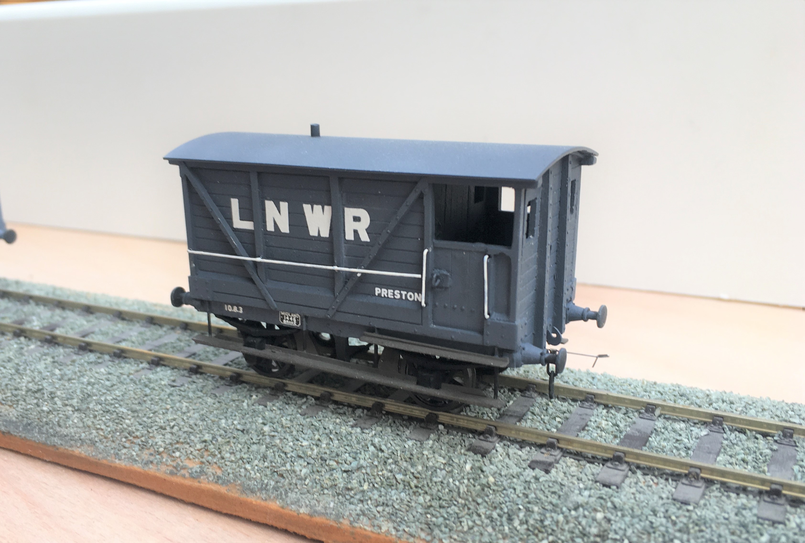
To finish of this little rake, I obviously need another brake van. This is not so obvious because this is brake van no 11 in the collection and I know I have at least one more spirited away! Whilst this was a kit build, it was first a kit unassemble as this was a vehicle I had first built in my teens. Generally fairly well but a couple of bits had got damaged over the years so I felt it needed rejuvenating.
And here they all are on parade.
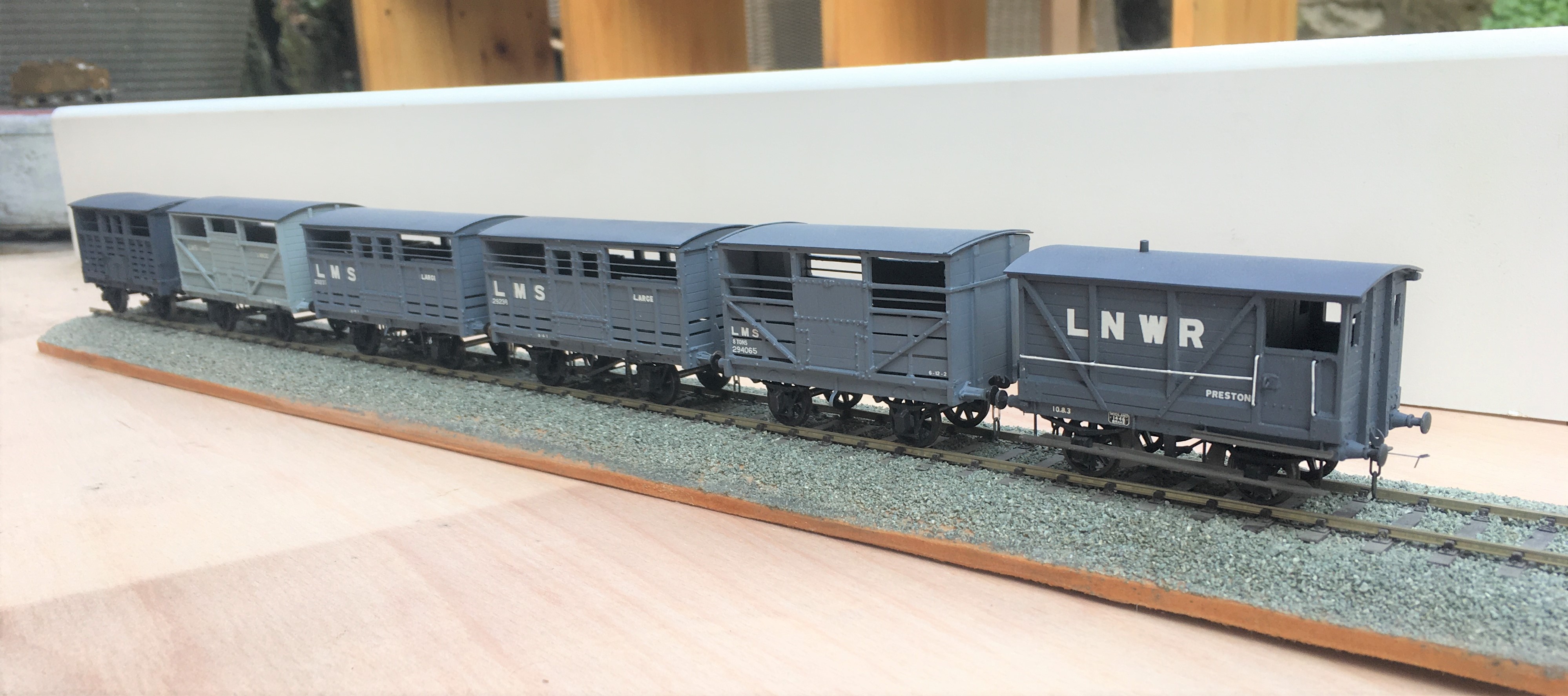
Now all I need is rather a lot of heilen coos to fill them up with. I have been working on this but it seems that resin casting is a tad more difficult than I thought……………..
Oh and yes, they are all way to clean; another weathering sess’ is required guys………..
What did you do during the war grandad?
This post is a bit of an apology because I have been so quiet on here of late………
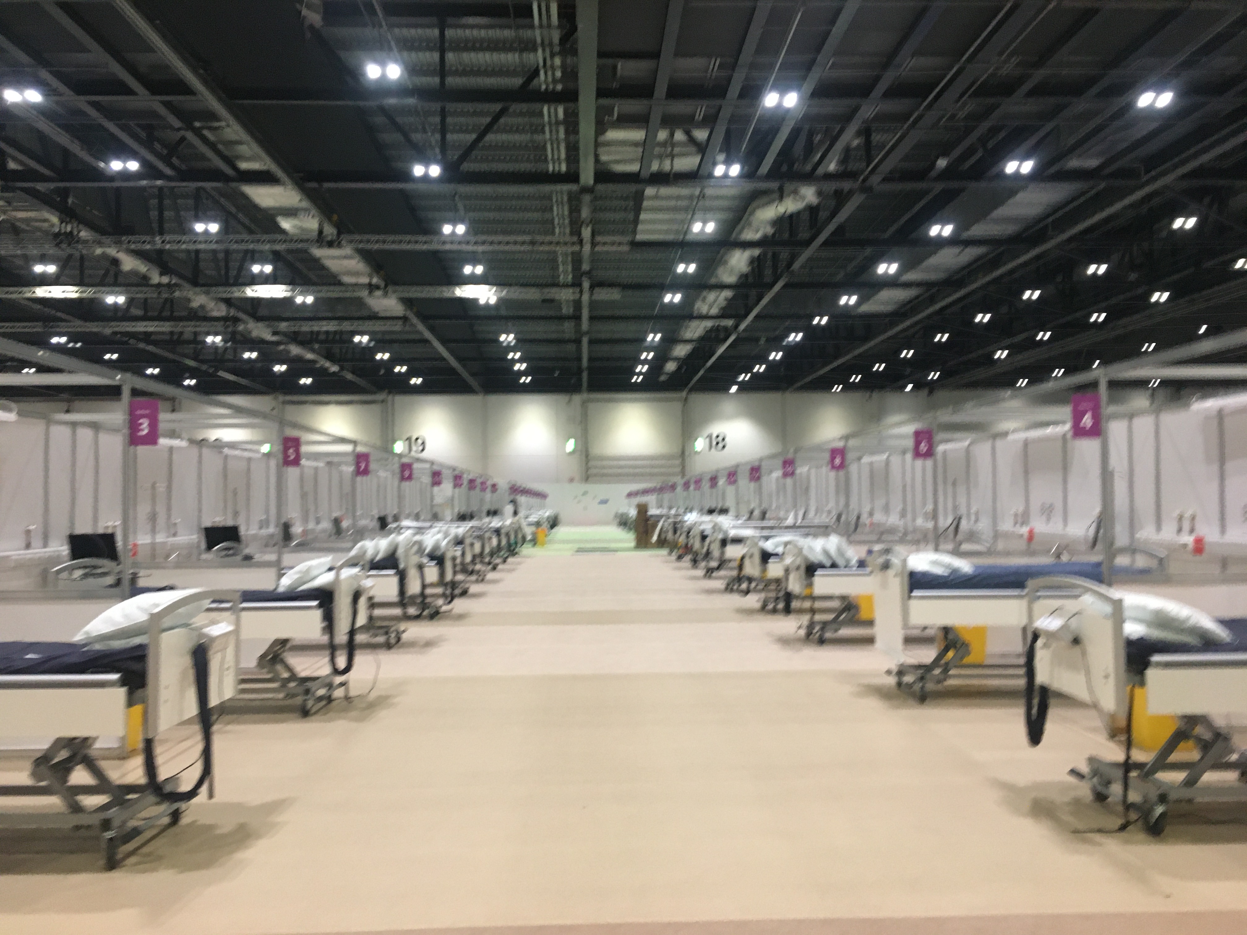
I do have my excuses though; related to the Covid pandemic none of us are enjoying. I have been pretty busy at work dealing with these places – the Nightingale Hospitals. I am not encouraged to say too much, especially given as I write this the pandemic is clearly getting a grip of the country and world again. I can say that so far, I have been inside five of the seven of them and I expect to see at least one more. Just to ensure I know what it is like for the hospital’s customers, I also decided to get a dose of the virus (with many thanks to the kids at my local school passing it to my wife).
So in the future when I have grandkids on my knee (not too soon please kids……….!) asking me what did I do in the 2020/21 covid war, I have something to say!
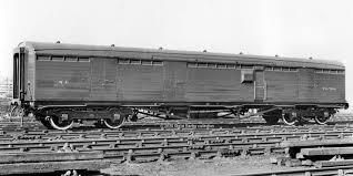
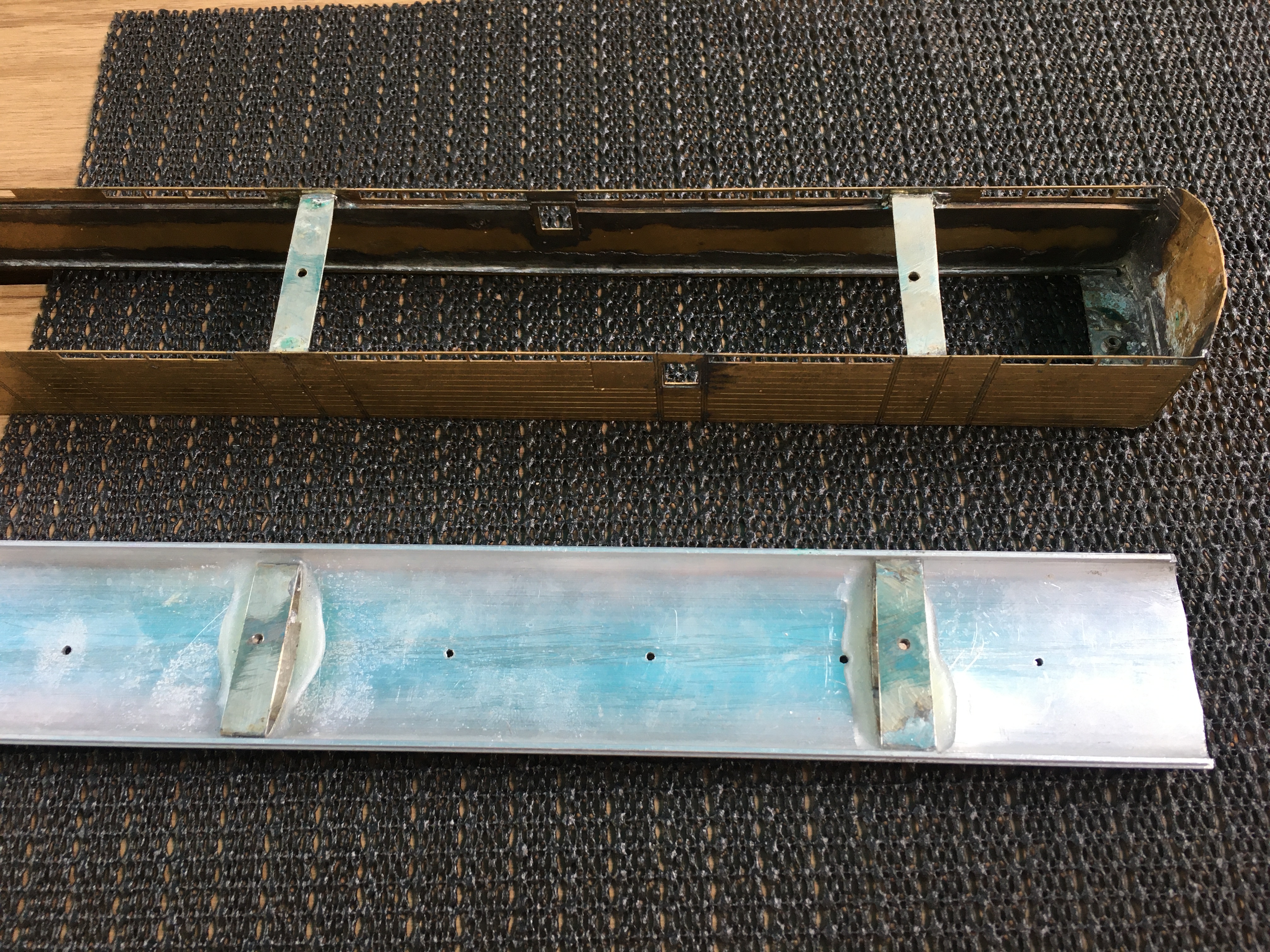
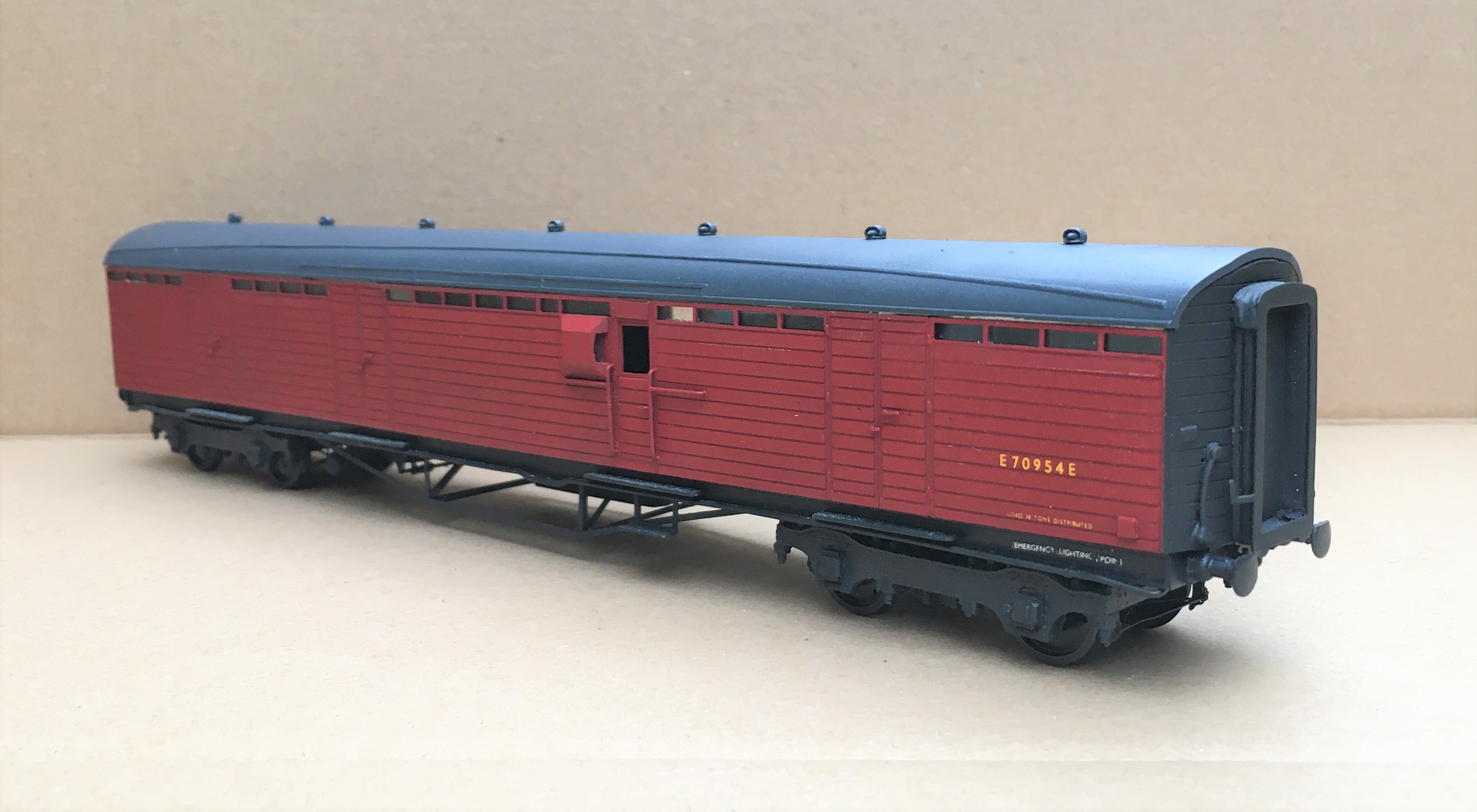
I have also allowed myself to go off in a tangent a little, as I have had a crack at a Thompson full brake. This was produced during WW2 when shortages of materials meant that they were built with teal planks rather than either teak or steel panels. The sides are flat without a tumblehomes and were unlike anything else on the LNER at the time. Steve Bank’s website has a lot of helpful information on these along with a good number of photographs, well worth a look at. This is an LNER official picture of the as built vehicle.
Now this was chosen in part because I thought it would be a nice easy kit to make and part because I wanted to use some of Justin’s new sprung Gresley bogies; hmmmm it didn’t come out quite like I planned! The first little set back I discovered was that the prototype was on 8’0″ bogies, not the LNER’s normal 8’6″ equivalents. So having taken a good look at Justin’s bogies, they were slid back into their packets to await a future project (I sense this full brake will be getting something to run with it fairly soon!). Instead, I used some of my Fox bogies from which I omitted the detailing elements and substituted some MJT cast sides which I had to file back so that they were not overly thick.
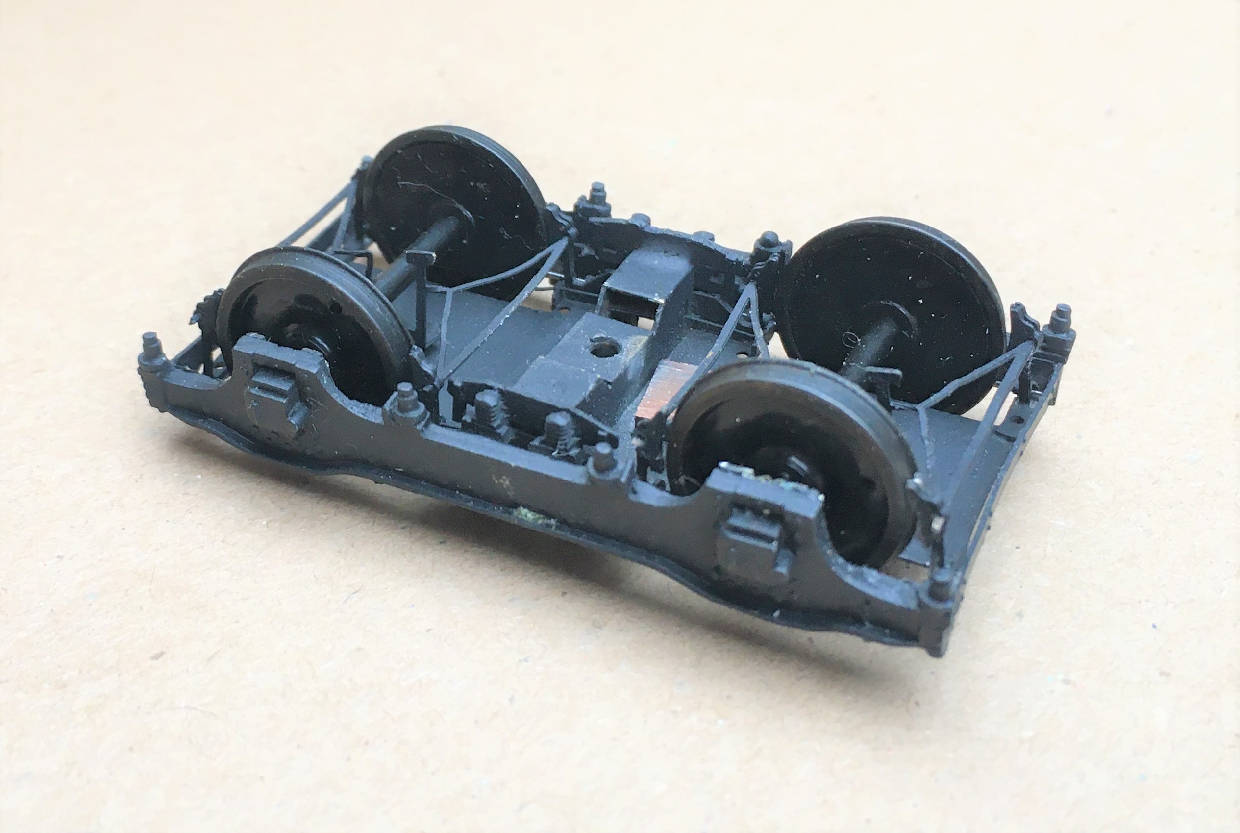
The next difficulty was with the Comet chassis, which I found to be somewhat clunky. I decided to ditch the fold down truss arrangements as they were only two dimensional. Instead, I used milled brass section folded up. It was a bit of a challenge to solder these together even the use of several different melt point as there are five separate sections to join at the same location. MJT do a suitable underframe too and I will be giving this a go for my next LNER coach )of which some are planned).
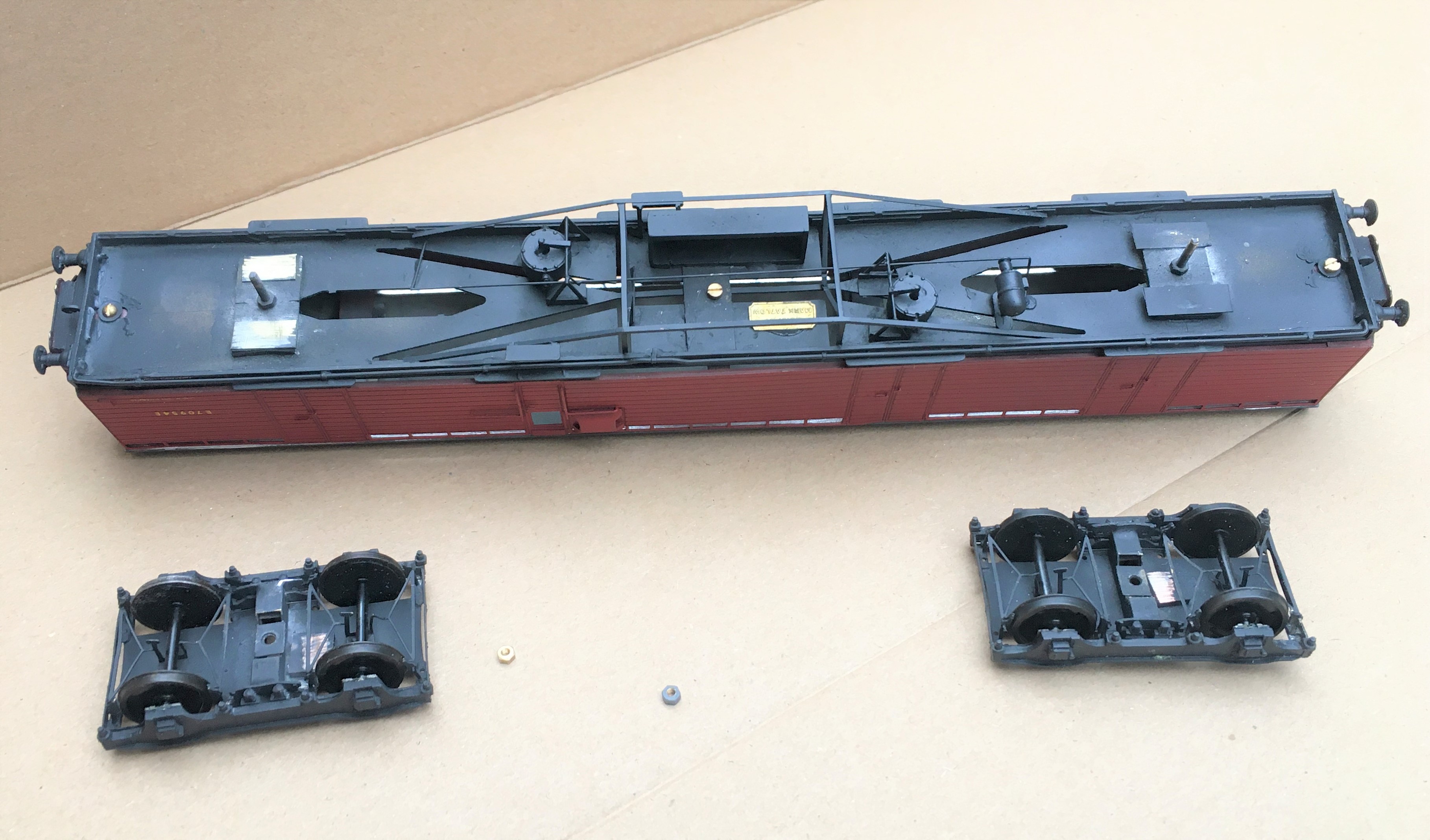
I now build most of my coaches with separate underframes and roofs. I then stiffen these up with a piece of 1*1mm brass strip at the head and 1*2mm at the base. The row of fan lights to these coaches meant that the former needed to be lower than I would have preferred and it needs the lip on the roof to keep these straight and in place. It is also necessary to put in some spacers to keep the side walls appropriately spaced without bowing. These provide convenient place to affix the roof with as can be seen here – although I did find the aluminium rather difficult to get the glue to attach to, it took no less than four attempts and a fair amount of liberal spreading!
I was particularly pleased with painting of this coach. Firstly, I departed from my usual paints (either Phenoix Precision or some cellulose paints I have had mixed) and took Jim Smellie’s advice and used paints sourced from Craftmaster. Craftmaster are supplies to the 12 inch to the foot heritage rail scene and claim that their colours are carefully researched by matching real samples. Certainly, their Crimson Lake is the one I am now most comfortable with, which is what I was looking for. I have found you need to spray them at a slightly higher pressure than normal and also a little more thinned but having done so, you get a clean, neat and very opaque layer. It does need to be left several days to properly harden, but once it has it is also the most durable paint I have experienced for a while (Humbrol in particular is not good these days I find).
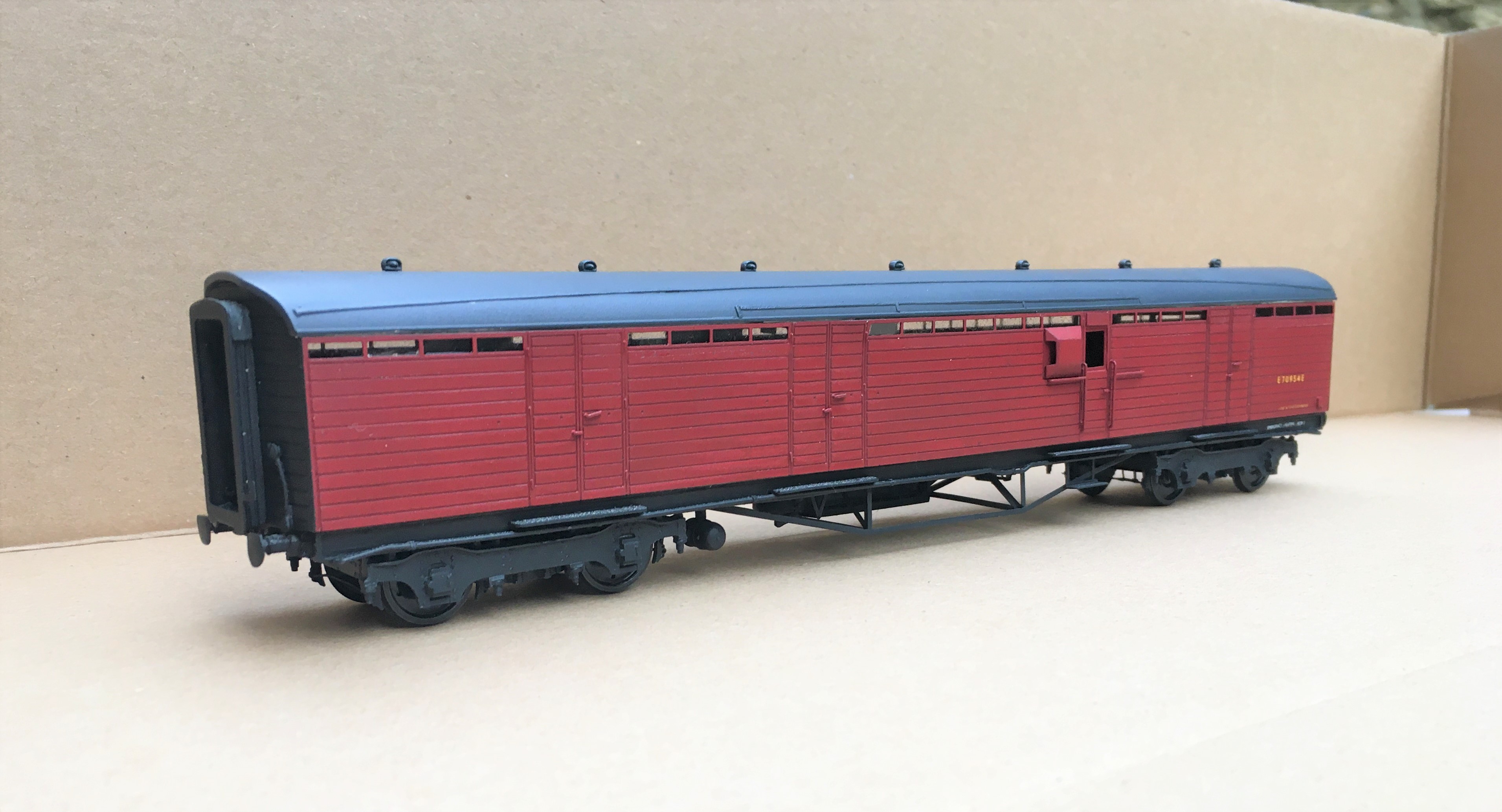
Once lettered, I sealed this with a coat of Dullcoat but it seems that the matting agent in mine was just beginning to turn as it slightly lightened the BR maroon. However, for a parcels full brake I was pleased with the effect, but I do need to be careful where a full passenger livery is required. So one more for the next weathering session – parcels stock from the 1950s onwards were typically shocking!
Scaleforum at a Screen Near You Soon!
With these strange times that we have been experiencing for the last six months, we have all become a bit cooped up in our abodes. Whilst the lack of model railway exhibitions is hardly going to make the six o’clock news (can you imagine!), I for one have missed both the inspiration and the camaraderie they offer.
We have not seen a plethora of on line exhibitions so it is welcome news to see the Scalefour Society making the effort to arrange one in place of their annual exhibition. This will “take place” on Saturday 26th September between 10:30 – 5:30 although it seems much of the content will be available thereafter online. Here is a trailer for it:
In addition to seeing familiar faces again, I was particularly struck by the possibility of seeing a number of “home layouts” that we don’t ordinarily get to see – and some big ones at that!
Some seems to be by video and others by an interactive youtube link so that you can chat to the team/person. This is the listing of what is proposed.
Layouts:
Boston Frodsham by Mike Knowles
Bristol Barrow Road by Robin Whittle
Central Cheshire Lines by John Sherratt
De Graafstroom (P87) by Vincent de Bode
Drighlington and Adwalton by Steve Hall
Eridge by the Kent Area Group
Faringdon by Rex Davidson and Stephen Williams
North Elmham by the North Norfolk Area Group
Obbekaer (P87) by Geraint Hughes
Pwllheli by Jonathan Buckie
Southwark Bridge by Mike Day
United Mills by Ray Nolton
Demonstrations
Adrian Musgrave – Signals
Alistair Ford – Timber Buildings on Black Gill
Brian Hingston – Coaches
Chris McCarthy – Baseboards
Dave Keeler – Wagon Construction
David Brandreth – Resistance Soldering
Jim Smith Wright – Soldering White Metal
John Farmer – Scenics
Mick Moignard – DCC Sound
Nick Rogers – Wagons
Rod Cameron – Lewis Project
Stuart Holt – Tree making
Illustrated Talks
Martin Nield – Authentic Model Railway Operation
Jim Summers – ‘Earning a Living’
I can see that chunks of the readership of this blog are dispersed in far flung places – take some time to see some really good 4mm without burning your air miles. The details to the log in can be found here:
So I know what I will be doing with much of the 26 September…………………. I will even make sure I have done some on-line shopping at about the same time so that Scaleforum hits my pocket in the same manner as usual!!

19 August 1870
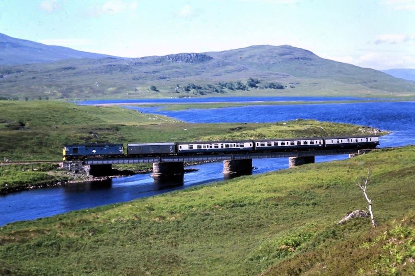
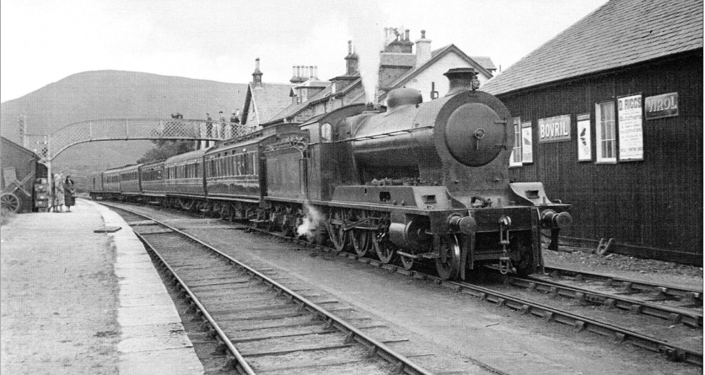
This day, 150 years ago, was a significant one for the highlands and the western isles. It marked the opening of the first railway to reach the Atlantic north of Helensburgh. To understand how significant this was, take a look at a map and and see what proportion of the country this represents – its almost a third of the country.
The line at the time was called the Dingwall and Skye Railway but nowadays we know it a little better as the line to Kyle of Lochalsh. Given it is the primary inspiration for my layouts, I think this anniversary needs to be marked with a blog post!
The original name of the line gives away the objective of the promoters – to bring communication to the western side of Scotland, in particular the islands such as the Isle of Skye. Given that even in the 19th century the centre of the country was very sparsely inhabited, the population was concentrated on the coastal fringes and on the islands. Prior to the arrival of the railway, to ship goods or travel to the islands from the lowlands would take days. These poor communications inhibited the development of these parts and the arrive of the railway was a major spur to the prosperity of the region.
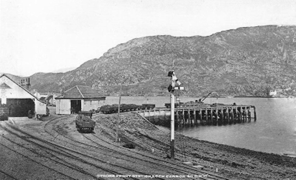
Despite the value to the region, the line was not constructed with the support of the government, instead it come about entirely with private finance. Given the sparseness of population, this was a brave venture and the promoters did not have sufficient money to reach their ultimate destination – the Atlantic seaboard. Instead they only just managed to reach a long finger of a sea-loch, Loch Carron. This was only intended to be a temporary solution to allow some income to be generated before the final push for the eventual terminus to be made. As with the best of plans, it too a long time for this ambition to be realised as the line to the present terminus at Kyle of Lochalsh did not come to be for a further 27 years.
The line started from the route up the east cost of the northern part of Scotland from Ross & Cromarty’s county town, Dingwall. It was intended to run through a fairly significant spa town, Strathpeffer, but this plan was foiled by an obstinate landowner. Perversely, therefore, the line bypassed the most significant town on the route, which hardly helped its finances! Whilst the line then travelled through sparse countryside with few centres of population, there were a series of roadheads where glens branch off. A feature of the line until the 1980s were buses coming to meet each train to provide links to the other parts of the west.
The line is a remarkable survivor as it was chalked up for closure on several occasions. Its most significant saviour was the oil industry in the mid 1970s, when the country’s biggest dry dock was built not far away at Loch Kishorn and the prospect of increased traffic persuaded the government to refuse a closure request. This prompted the railway to make efficiency savings; for example the line was the first example to use a radio signalling system 40 years ago.
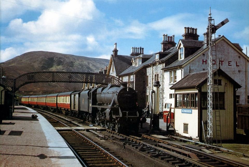
The line survives to today in its extended form to Kyle of Lochalsh and (touch wood) seems to be safe for a long term future. Ok, it has a lot less charm as a railway than it used to but the scenery is still second to none and you still have the romance of heading to the wild west of Scotland – it justifies being seen as one of the worlds great railway journeys! If you have never done it, then it really needs to make your bucket list!
If you want to enjoy the charm of the line in the era that Porthcullin is set, this is a link to a fabulous video created by Ross & Cromarty council in 1972. This was deliberately rose tinted as it was a promotional tool to seek to convince the then government not to allow its closure – indeed, it was shown to parliament at the time and may even have had a hand in the saving of the line. After all, you don’t just arrive at magic, it has to be conjured…….
As an alternative, if you do want to find out more about the line there are a number of good books on the line; including one by my father I mentioned here.

Euston Departure
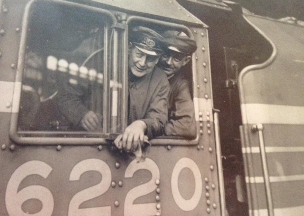
Being fundamentally an LMS man, I have recently joined the LMS Society. The cover photograph of the first Society newsletter that greeted me was so fabulous I thought it was worth sharing.
This is 6220 Coronation awaiting the right of way from Euston, sometime between June 1937 and the outbreak of the war. Driver Fred Bishop is peering out of the cab roof ventilator in what must be an official photograph posed shot for publicity purposes.
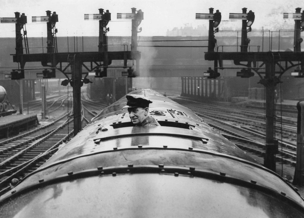
Coronation was the first of the Coronation / Duchess class introduced to pull the LMS’s premier train, named the Coronation Scot, and inaugurated on 29 June 1937. This was launched in competition with the LNER’s comparable train which was launched a week later and called the Coronation. Both trains were named in honour of the coronation King George VI.
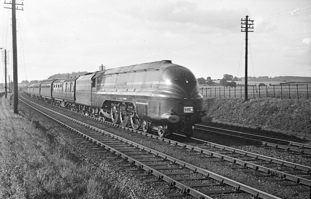
On its inaugural press run Coronation became the world speed record holder with a speed of 114 miles per hour on Madeley Bank south of Crewe. Unfortunately the jubilation of taking this record became consternation as the footplate team realised the train was still making 110 mph only a mile and a half from Crewe. Urgent braking brought the speed down but the locomotive still passed through the station’s reverse curves at 57 mph, well in excess of the 20 mph limit. The resultant bouncing alarmed the passengers and destroyed a quantity of crockery in the dining coach! It discouraged more record breaking attempts for a while, although famously the LNER’s Mallard retook the accolade in July 1938 with a record that still stands today.
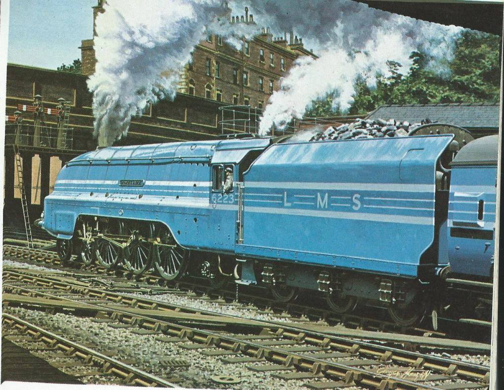
Whilst I am not against the A4’s, surely the blue Coronations with their stripes and a matching train behind had the ultimate wow factor of the pre-war railways?
What tends to get forgotten these days is that in the 1930s the top link drivers on the crack trains were major celebrities of their day. Had Ant & Dec existed back then, you would have found some of them in the jungle alongside annoying footballers and has been musicians! Fred Bishop was one such driver and his auto-biography (Queen Mary of the Iron Road – Jarrods, 1946) was a well known book of his time. It seems a long way from the grime of the inside of a locomotive cab being worked hard!
Only the first batch of Coronations were painted in blue; the second set of streamliners were in Crimson Lake with gold lining and were aimed at hauling prestigious but not bespoke trains. This (I think) is King George V and is in this livery.
Whilst they may have only really existed in this form for three years (as once war was declared, many were painted black and they were de-streamlined after the war), the LMS streamliners do hold quite a soft spot in my heart!
Hornby already produce a very good model of the locomotive and are shortly to produce a number of the matching coaches; maybe I will be able to resist, maybe I won’t!
photographs with thanks to Ian Beattie and Jim Smellie

Fuel for Thought
Obviously, where there is water in a locomotive yard, there really ought to be coal too.
The Highland, like many other railway companies of the time (certainly the Scottish ones), sought to stockpile coal. This was presumably insurance against coal strikes and allowed them to purchase coal at times when the price was favourable. Thus, quite substantial coal stacks where very much a feature of shed areas in the pre-grouping era. Typically, these were arranged in engineered stacks, with the sides formed in “dry-coal walling” and then loose coal behind. I can’t recall ever seeing this modelled, so I though I would change that!
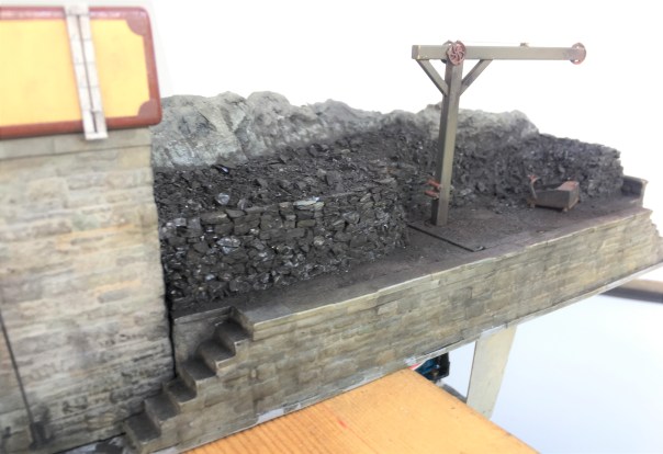
The actual structure of the loading bank was formed in plasticard and Wills random stone sheets, but with the mortar courses softened as I described for the water towers. The shape of the coal stack was formed with a piece of house insulation left over from a DIY job and then real coal used to form the effect of…..err……real coal. Actually, real coal does not look quite like real coal without a bit of effort. It does shatter into angular but irregular lumps like real coal (especially if lignite coal is used) but its glossiness does not scale down. However, a vigorous brush with generous amounts of soot black weathering powder takes the gloss back and the whole becomes quite convincing. You do feel as if you are going to get pretty filthy if you go up onto the bank – and until the whole is fixed with matt varnish, you would!
Individual coal chunks were glued in place to form the wall structure. To get the effect, it is not enough to simply scatter the coal onto a bed of glue each chunk has to be laid individually with care taken to lock it into the course below – just like a real dry stone wall. Thus, the vertical walls of this took about a day to complete, scattered over about 8 stints because it is necessary to let the glue dry after every couple of courses to stop the layers collapsing. It is then possible to scatter the loose material behind the walls onto a layer of glue – the above picture shows the contrast in effects between the two methods.
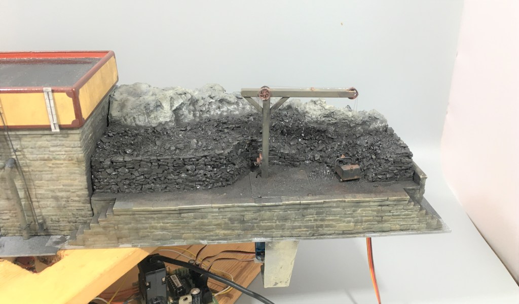
But it is hard work shovelling coal into tenders, especially as the locos got larger and their tenders higher. As befitting such an important place as Glenmutchkin, it has all the modern amenities for coaling engines, a hand crane and a large bucket! In this case, I have fitted servos to this so that it operates – partly as a bit of fun and also to slow things down in the yard to a more realistic pace without it getting too boring for the viewer.
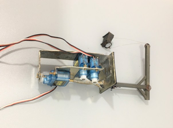
The crane operation was achieved by way of three servos – one to rotate it and then one each for the front and rear of the coal bucket. These are all mounted onto a cradle that is rotated by the former – thus as the crane rotates so too do all the servos and there is a quadrant shaped slot in the base to the rear of the post (just visible in the picture above) that allows the cables to rotate too without snagging.
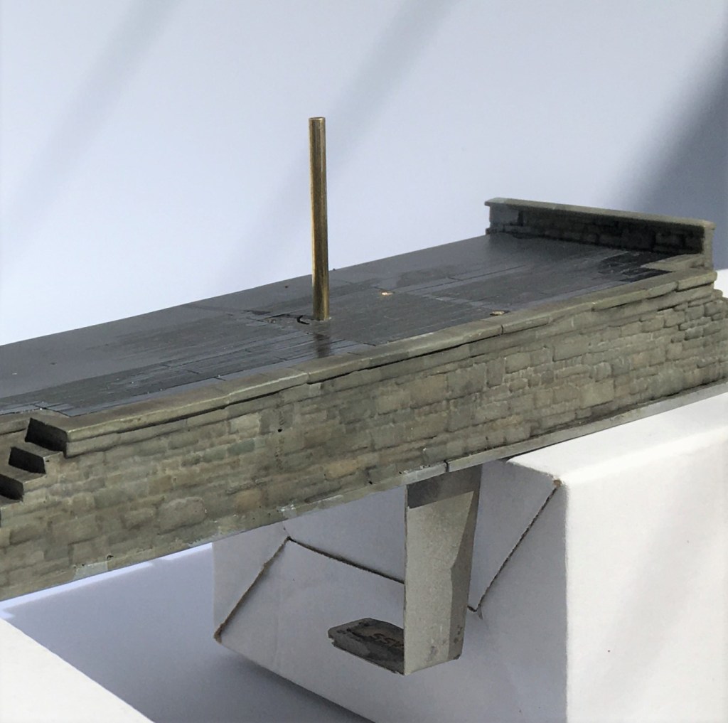
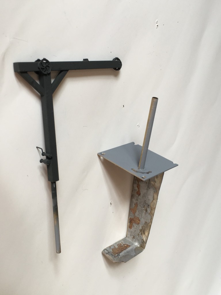
The cradle is mounted to a solid rod that is in turn secured to the actual crane. This then slides into the rod that can be seen projecting from the base in the picture above. This means that there is limited strain on the crane or the mount as I had feared it might otherwise snap with any heavy-handedness on my part (something I am prone to!). The rest of the crane was made with brass hollow section and pulley wheels from Bill Bedford. A series of guides were made of small section tube on the pulley wheels, at the winding drum and across the jib to retain the operating cables.
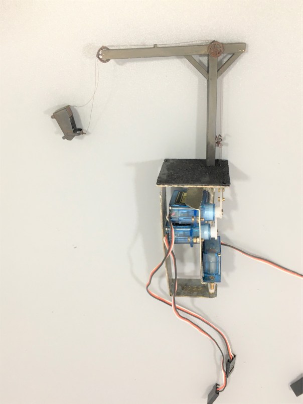
The bucket was fashioned from metal sheet and is filled with low melt solder to give it as much weight as possible. It is secured to the servo arms with invisible thread – which is a nylon seamstresses material used for making invisible stitches. It comes in both clear (which really is invisible) and black, I used the latter. It is much better than cotton thread as that has a furry finish that looks terrible after a time or if it is painted. It is, however, very fine and rather wriggly to knot, so using it involves a certain amount of cussing!
And this is what it looks like in operation…………
A little of the bouncing about of the bucket is caused by it sitting on my servo test rig, so the act of changing the switches imparts a little vibration. Hopefully, when mounted on the layout this will be less obvious.
I do still need to do the final detailing on this; tools, a bit of discarded debris and a couple of fellas from Modelu standing around doing nothing (because static people in animated poses look silly on a model layout!).
Only the printable words for this Wednesday!
Hmmmm……..
A signal imitating a Fresian cow was not the effect I was after…………..
Halfords etch primer is obviously not that etchy!…………….. So someone will be waiting a tad longer for their signal than I thought…………

And now a Midland signal…..
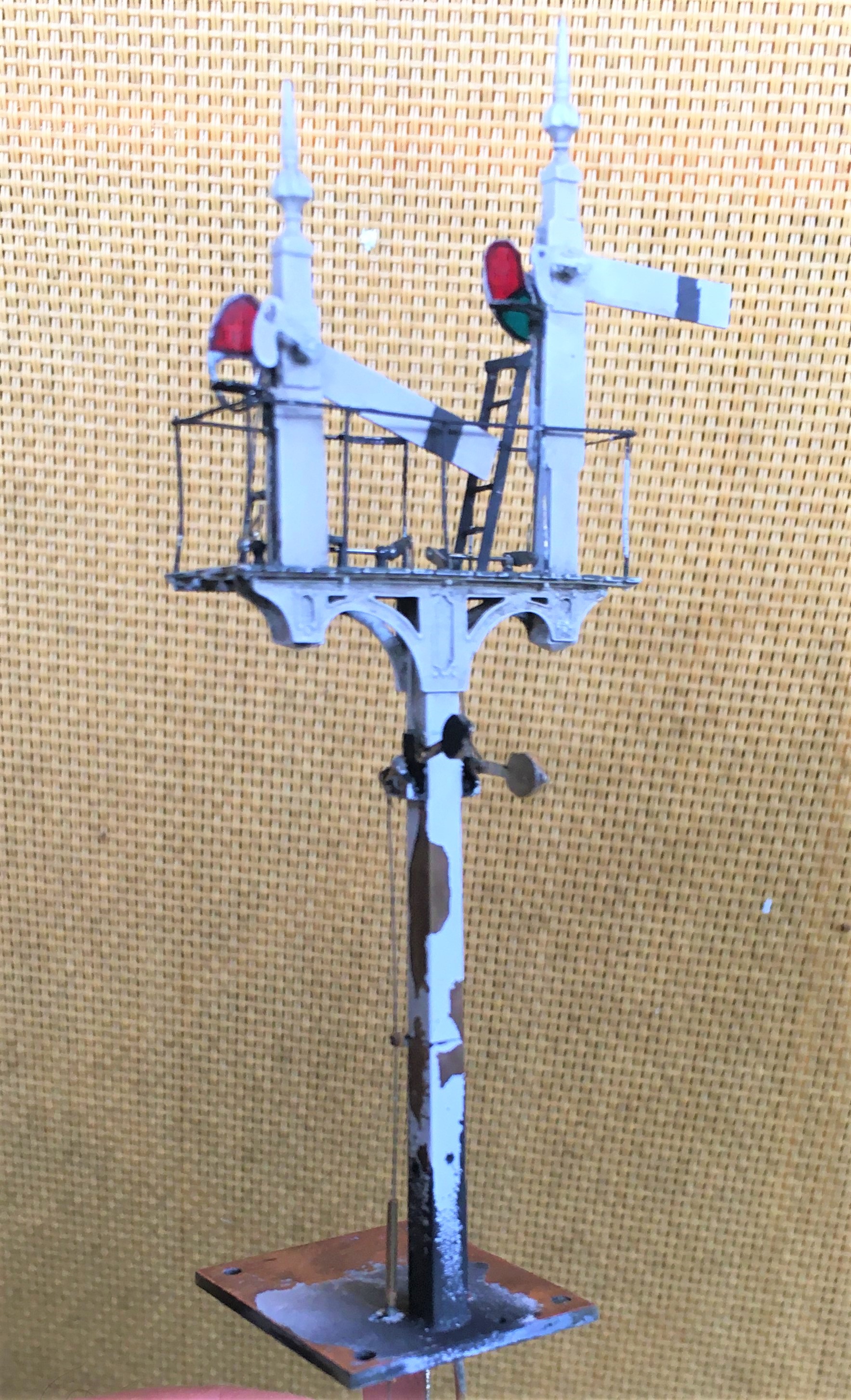
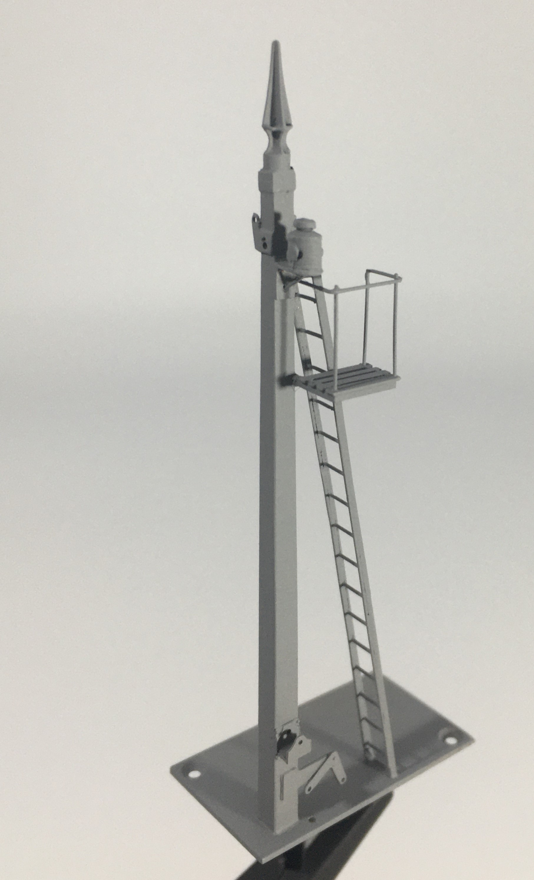
Whilst the NER signal from my last post gets itself painted, I turned my attention to the next few signals – in this case these will be Midland lower quadrants.
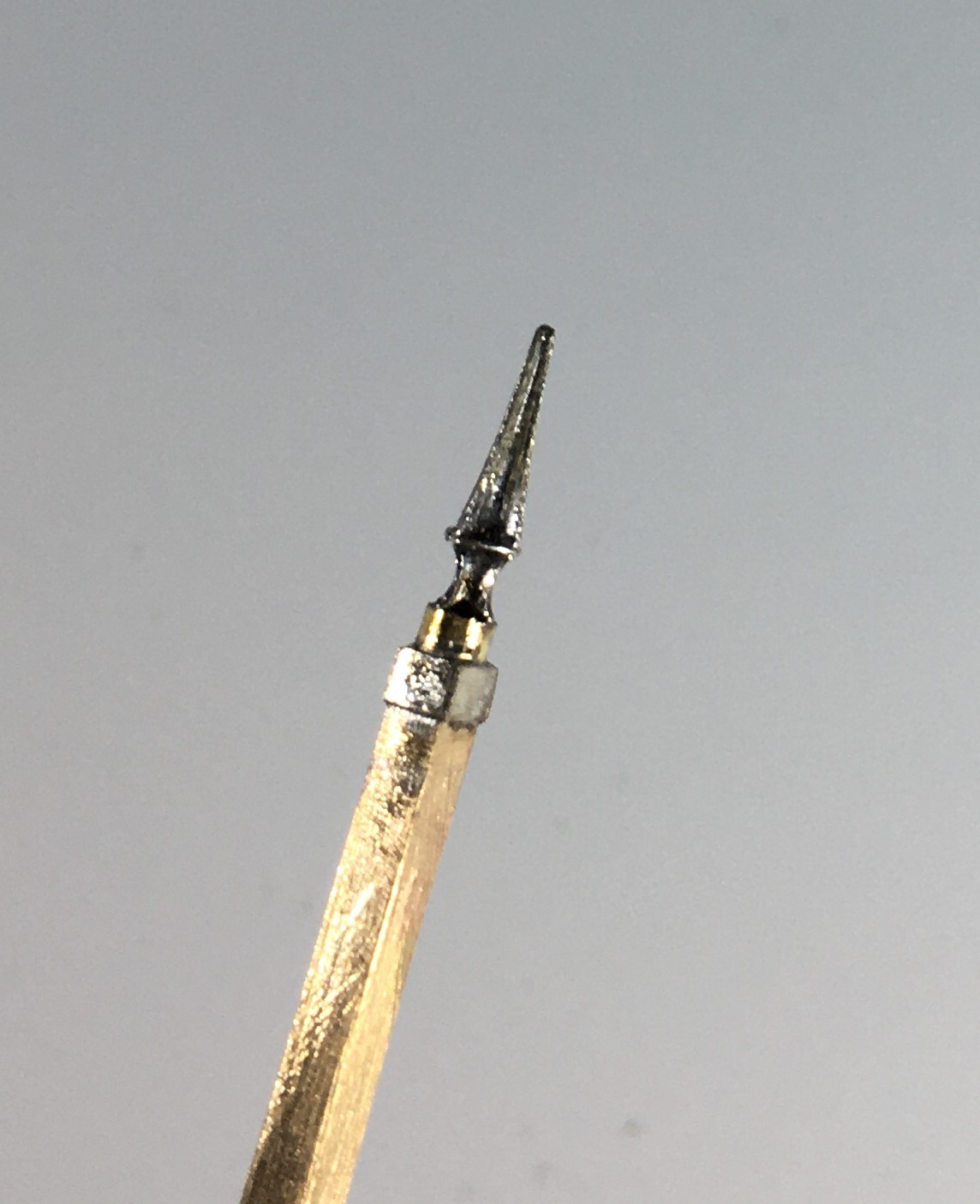
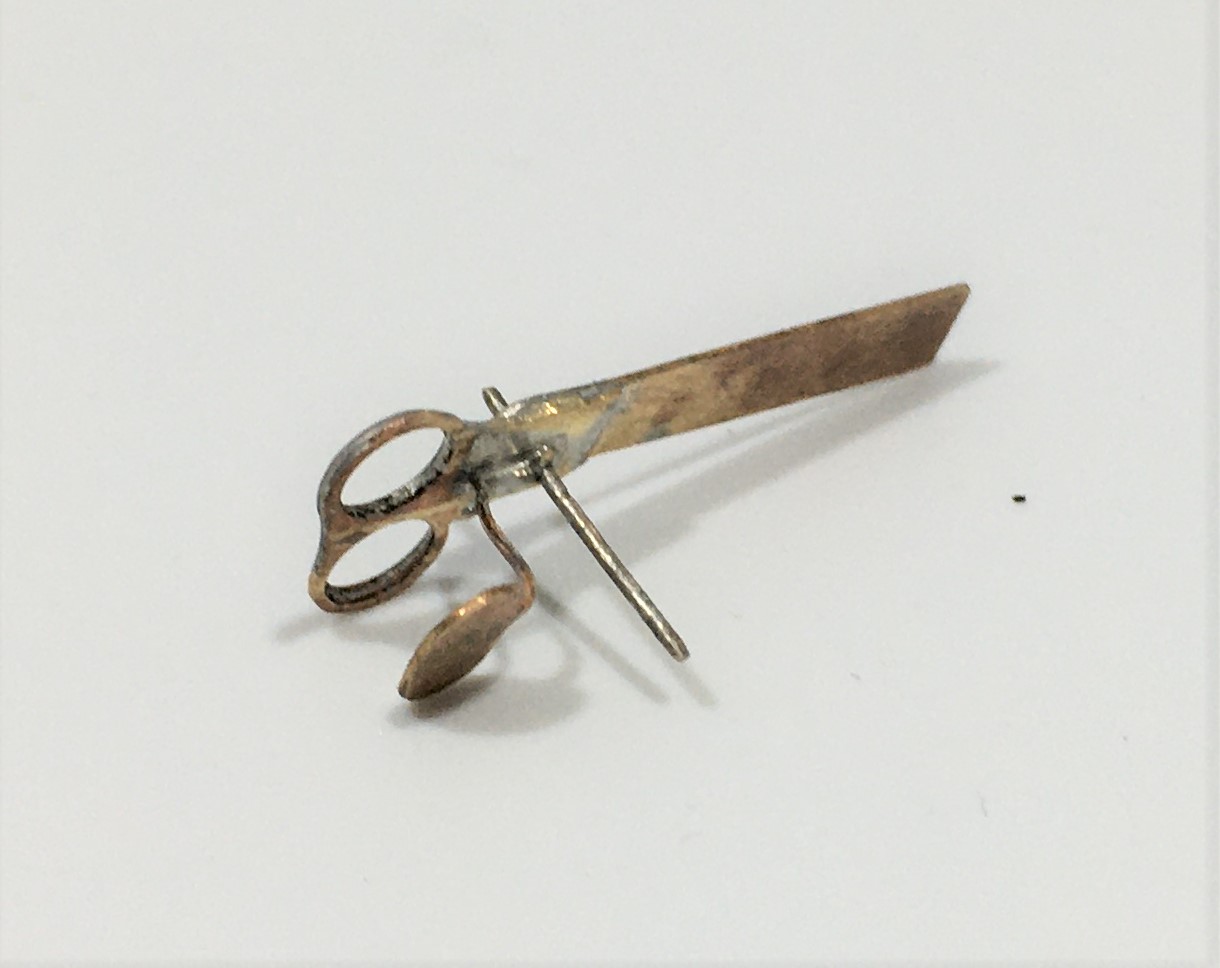
A lot of the character of a signal is in its finial and if this isn’t right then the model won’t convince. In addition, they are also very vulnerable so need to be durable. Therefore, my conclusion is that white metal finials do not cut the mustard – they are too delicate and too clunky. Thus, in this case I decided to make my own – I came up with this which starts with with some interlocking etches:
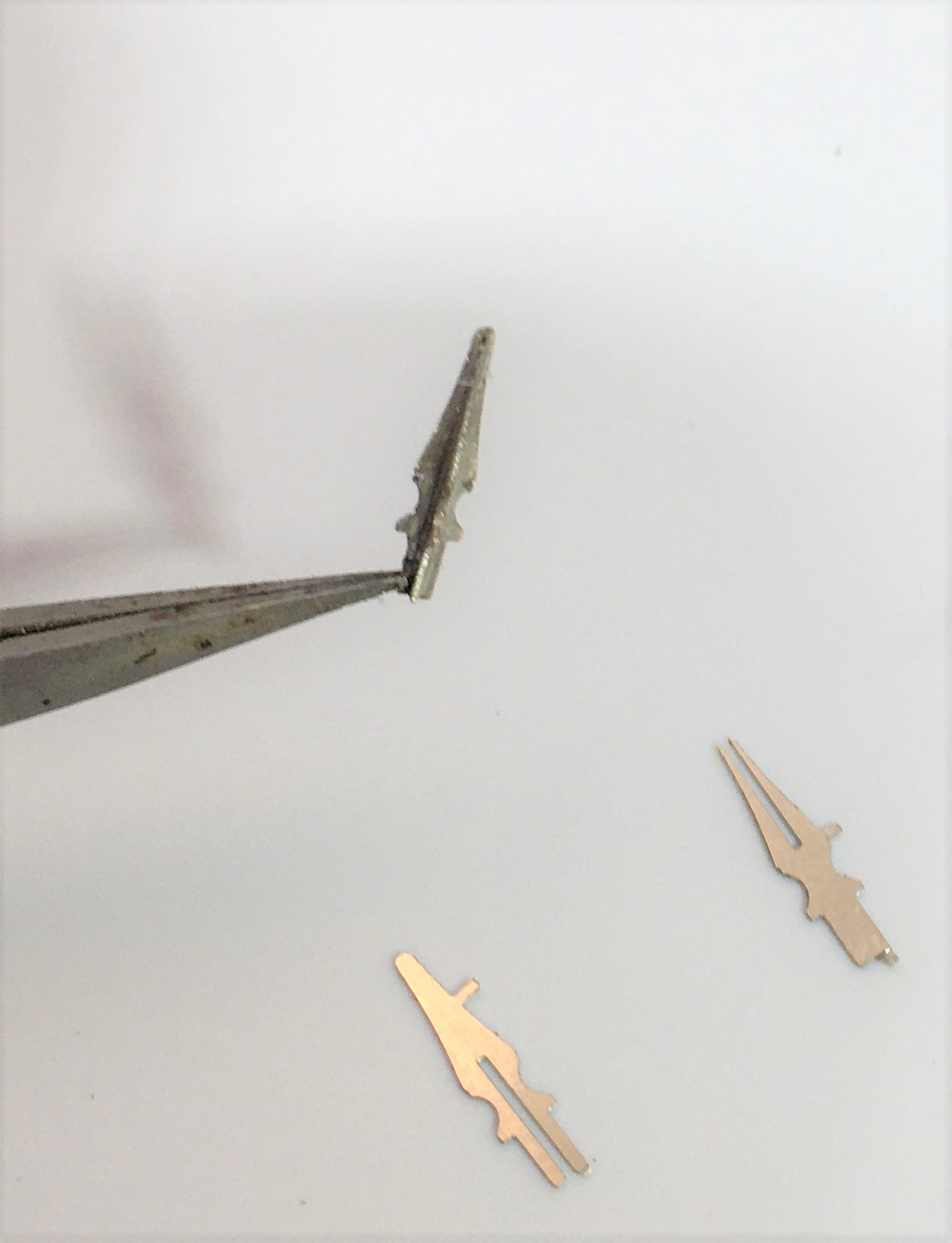
And then a bit of brass tube as a collar at the base
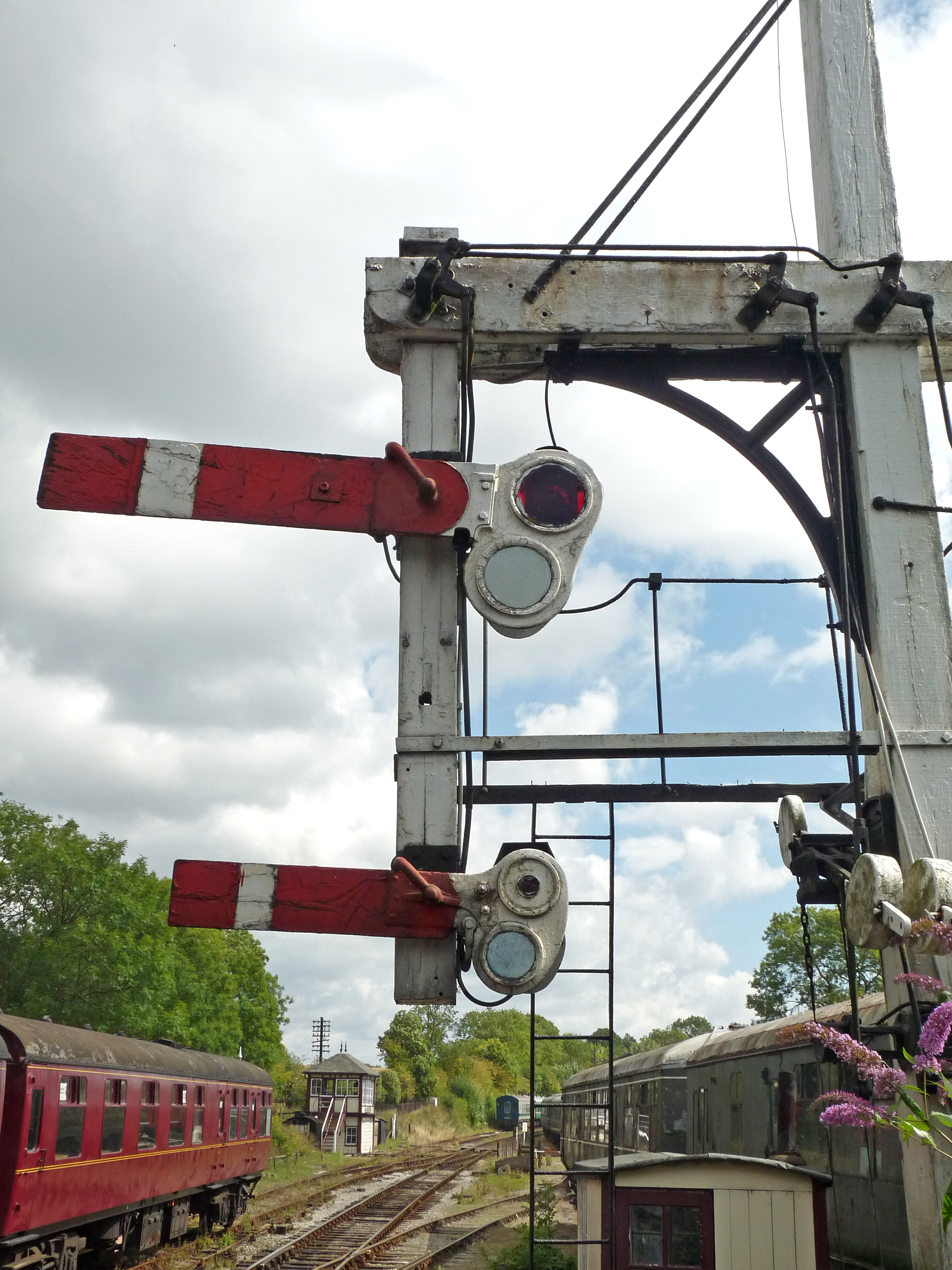
The Midland’s style of signals do have a few idiosyncrasies; one of which is the way that blinders are fixed. Instead of being fixed to the spindle these are secured to the arms and wrap around the lamp. This can be more clearly seen in the photograph below.
The other key change was in the manner in that the arms are secured to the posts. Instead of being pined through the arm and secured at the rear, the Midland used a bracket to the front of the post with a plate that wrapped around to the front of the signal to support the arm to the front. This can be seen in this view of a rather nice gallows signal at Butterley.
The bracket can be seen in this view below and I then created a pin that fitted into the bracket and slotted over the spindle.
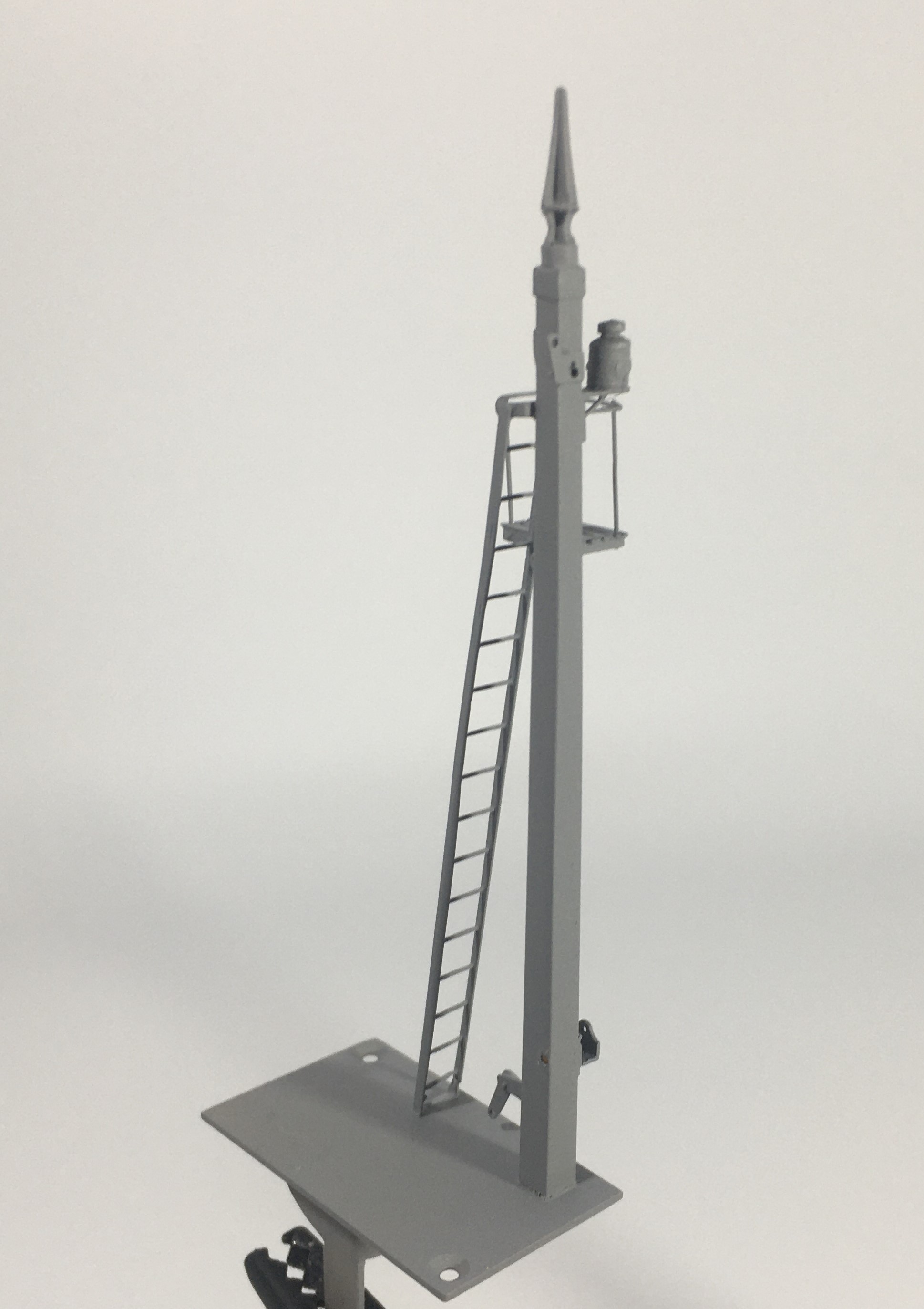
I have bought a new light box for taking photographs in. Whilst I am still getting to grips with it, when it works it does produce much improved pictures of models. These almost look like an images of a 3D model on a computer screen. The pliers at the bottom of these views do rather give the game away!
The Midland were a bit odd in their choice of colours for their signals. The posts were “primrose yellow” but this quickly dirtied to something akin to cotswold stone is what the book says, so this does give something a little different. This is my representation of this with a decent dose of smokey dirt – when you look at contemporary photographs many signals were not only dirty but entirely smothered in smoke. I haven’t gone that far yet, but its going to need to be done!
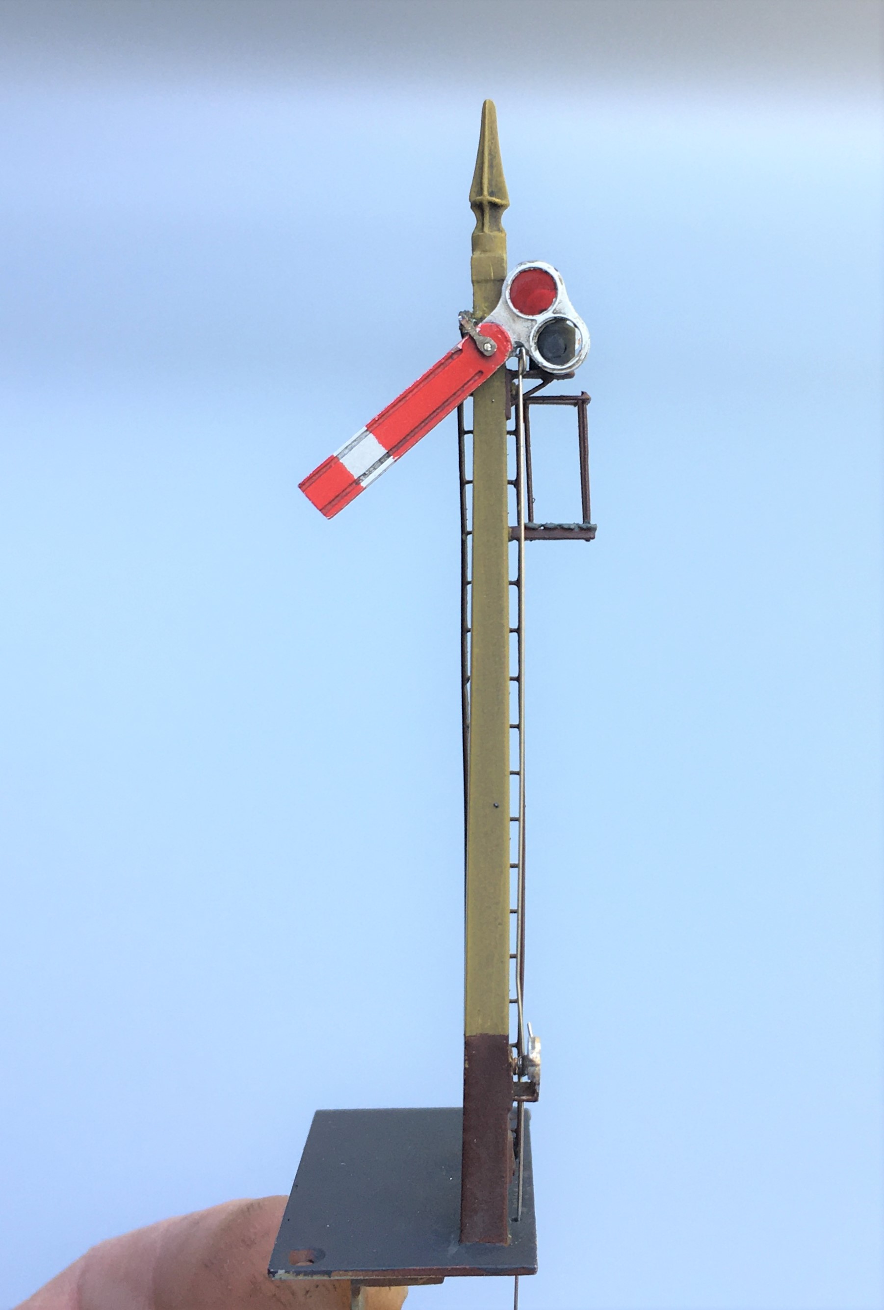
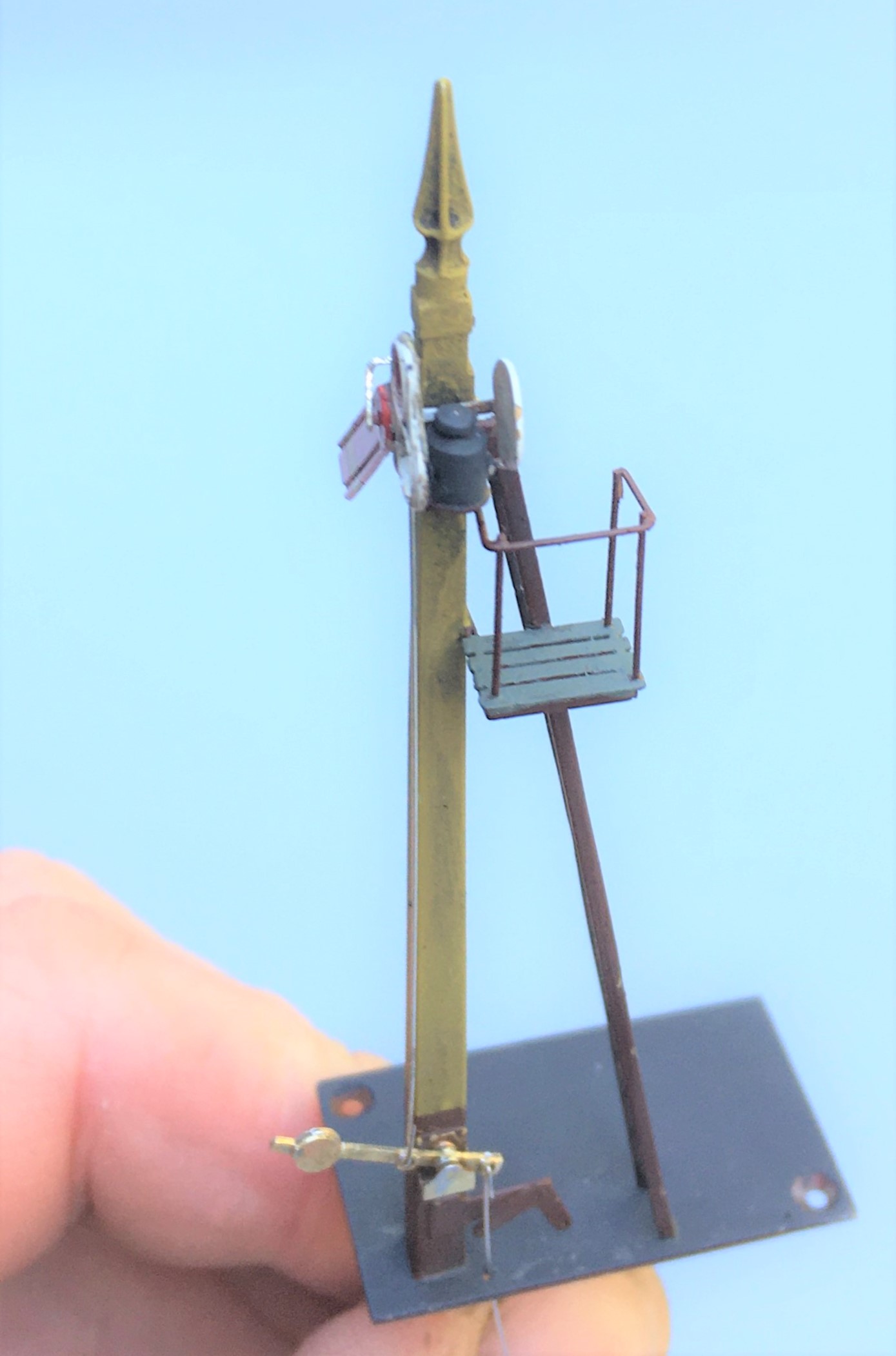
As can be seen, this still needs connecting to the servos and the touching in of the paint on the parts that I fit after the main assembly (the balance lever and the plate that wrapped around the signal arm).
