The Colour Red – or the Quest for LMS Crimson Lake
A topic that comes around from time to time, including to my lips, is what colour exactly is Crimson Lake? I thought that my analysis and that of others that have contributed to the discussions were worth sharing more widely; so here goes……….
The Historical Context
The first good insight I have is from George Dow who was a prolific author of the 1960s and 1970s, including on liveries who wrote in the Railway Modeller in 1973:
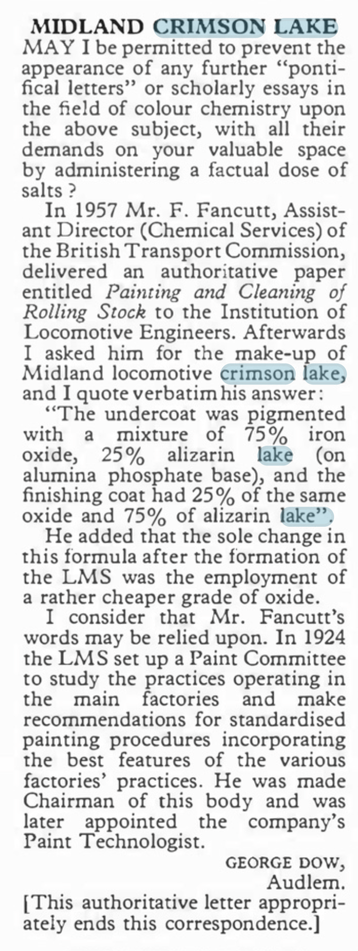
However authorative this is, fifty years later, with the change from natural to synthetic pigments this is not of great help. Also B&Q do not stock alizarin lake last time I looked as it is a pigment produced from a complicated processing of a vegetable and is probably fairly inconsistant anyway. https://www.winsornewton.com/row/articles/colours/spotlight-on-ruby-madder-alizarin/).
The Problem With Reds
Many years ago, when I was still in my shorts, I worked in a printing ink manufacturering business and red was one of our bugbears. This was for three reasons; as a colour it is less opaque than many colours so were prone to poor coverage, it is also prone to fading and like all paints, it is affected by the surface treatments, in our case varnishes. All of these issues affect how Crimson Lake appears on both the prototype and our models.
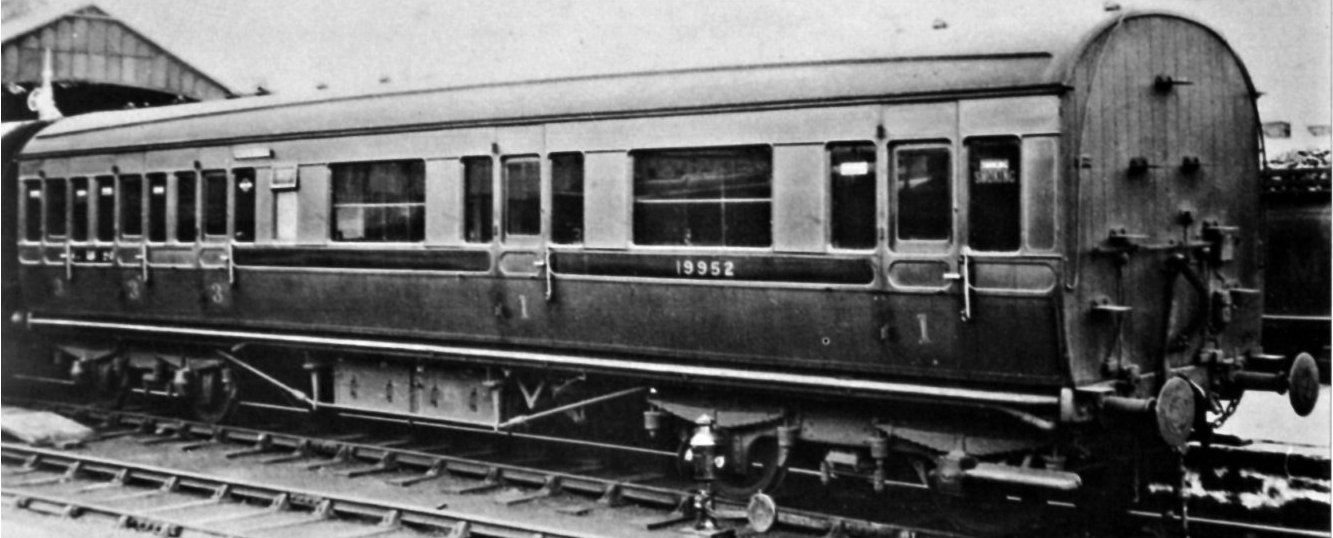
A Caledonian diagram 106 non-corridor composite shortly after being renumbered to 19952. This appears to have been acheived by painting over the predecessor number and then the application of the fresh number and then varnishing. The patches that have been so treated stare at you somewhat and ilustrate how the paint and lustre deteriorate! Photo by H.R. Norman ref 6081 and now in the NRM
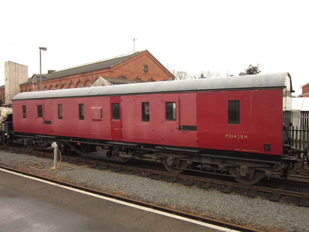
Its still a problem now too as this diagram 2171 full brake at Kidderminister shows. Photo SVR Enthusiast via Flickr
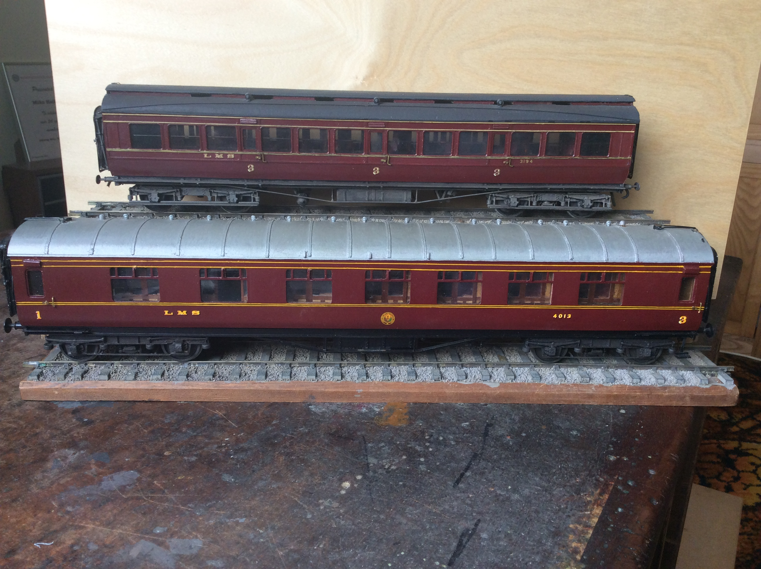
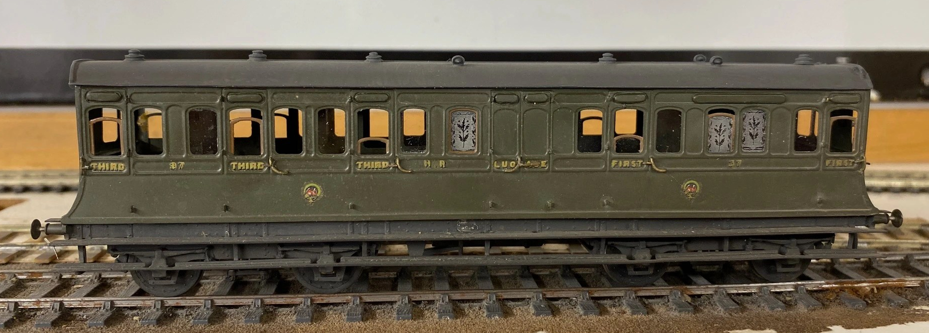
Both of these coaches have been painted in the same top coat, Precision Paints LMS Crimson Lake. The top coach, the clerstorey, followed the paint sequence noted by George Dow above – a first undercoat of LMS wagon grey, followed in turn by 75% grey, 25% crimson; 50% each; 25% grey, 75% crimson and finally 100% crimson. On the lower coach, the crimson was neat and painted over an undercoat of LNER bauxite. Both were painted at the same time, in otherwise the same manner and in both cases they were varnished but not weathered. The difference is startling! Photo and models by John Hastings Thompson.
Does Colour Scale
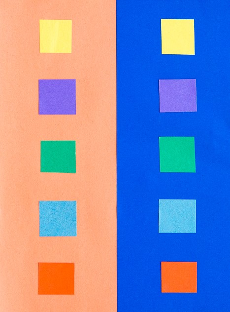
Like weight, I am not convinced that colour scales or perhaps it does but given that our models are smaller than the prototype it is more heavily heavily by contrast. I am sure we all know about the optical illusion causing the viewer to read differnt colours of the same sample by virtue of the background – is this happening to us as we perceive the colour of a model? Try the sampel from the Exploratoium below:
The presence of lining is also a major influence of the feel of the colour. The gold and black of the LMS seems to add a bit of sparkle and depth of colour to the red.
It was a Long Time Ago
We must also remember that the last LMS crimson lake locomotive or coach will have been repainted seventy years ago and even the last BR maroon loco was withdrawn sixty years ago (plus there is the argument as to whether they realy were the same colour as well!). Whose memory of colour is good enough to survive this long? Even photographs from this era as a whole cannot be relied upon due to the variability of colour rendition, the nature of the light that the subject was recorded in or the level of contrast with its surrounding – none of these issues have gone away with modern digital photographs!
I for one have never seen either original colour and my view of what crimson lake is being based on the preserved locomotives that I have seen over my life. Have the preservationist got it right? Maybe they are better informed than you or but if this was true, why is there so much variation in the colour from the ready to run manufacturers or even the paint manufactuers?
However, whether they are right or not, the preservation scene has set my expectation of what the right colour is and I suspect the same would be true for all of us. Whilst I hate making modelling decisions on any history which is not real, I have reached the conclusion that the right colour for me is one that matches what I have seen in the UK preservation scene.
Where does this leave us?
Possibly the first conclusion is that there are a wide variety of reds that we can safely consider to be correct for Crimson Lake – phew, because when I look at my models I do have variences!
The second conclusion is not only is some inconsistancy acceptable, it is actually essential because red faded so noticeably. I am less convinced that the changing of hues seen across some colours but a toning down of the colour and tinging to a more matt colour is definitely prototypical.
In my personal quest for a colour I have been through multiple agonies to get the right colour. Thirty years ago, it was Precision Paints Crimson Lake but this seemed (to me anyway) change and become too purple over time. I then used Rover Damesk Red from a rattle can but found this too uncontrolable or, if I held it further from the model prone to to giving the orange peel effect. I was then put on to the solution to all our colour problems by Jim Smellie (of Caley Coaches).
This suggestion was to use the colour that the preservation industry generally use to source paint for the 12 inch to the foot models. This comes from Craftsmaster paint who have a series of specialist railway colours for most of the colours that we will wish to use. I use a numberof their colours including Crimson Lake. I have yet to adulterate this but i do intend to let it down with some white to imitate fading – hopefully this will not send me down another quest for the right faded Crimson Lake!

Delayed Delivery – Part 2
Once the basic structure of the gantry is in place, the real task of making the signals signally commences. First up were the smoke deflectors and the brackets for the balance weights. Also fitted are the main portions of the fan route indicator, but that will be explained further once I get it going!
For the arm bearing point and lamps I am using some 3D prints produced by Steve Hewitt and available from Shapeways. They can be found here https://www.shapeways.com/product/JJRSB … arketplace. They are fairly expensive but they are neat and save a lot of manufacture. There is, however, a but – they are very delicate and I am very fearful of thier long term durability. I am highly likely to draw some of my own up and get them cast in lost wax. It will make them even more expensive but I have about a 50% casualty rate at the moment, so maybe in the long term it will be cheaper!
The arms are Masokits, these are definitely the best available arms for LMS/LNER/BR semaphores. This is especially true of the minature shunt arms as the MSE ones are simply too delicate to bother with (imagine how do I know that………….!). So this is where we are now at with the arms mounted temporarly on the bearings.
There are five movements in the down direction (three of which operate via the route indicator) and then a pair in the up direction – hence the back to front arms.
The plates at the top of the dolls are mounting points for ladders. It transpires they are wrong and have already gone!
So the intensity level has dialled up a notch with these portions (especially breaking the bearing/lamp fittings) but it really gets interesting when you try and make these things work.
I don’t know myself yet (although I know for the couple of arms I have finished, so I have an inkling), but i think it might be fun to have a little sweepstake on how many moving parts there will be in the finished gantry. Five arms, three fan route indicators and each is operated by way of angle cranks. Each arm, crank and intermediate wire counts as a moving part, as do the servos………………..guesses please?

Delayed Delivery – part 1
After a long pause, caused by that irratating thing called life getting in the way, I am looking to deliver on some long made modelling promises over the holiday season.
The major task is a rather full on gantry signal with no less than eight movements on it (which is an improvement, when initially designed it had nine!), including a rather natty fan route indicator. This is for a friend’s layout and is in return for some signal cabins that he built no less than 15 years ago – I told you the promises were long made! Mind you, he hasn’t got the layout fully running yet, so I am still ahead of him!
The gantry spans only two lines so it can be formed with channel section. There are good drawings and pictures in LMS Journal no 5 of this. I have made mine from milled brass section and then the landing was a custom etch I designed as it takes a surprisingly large amount of material and effort to construct this from scratch. These etches included the doll base plates although the dolls have a thickened tube at the lower level which of course I forgot and had to undo later work to put on!!
The signal is to be located on an embankment which meant that I could not simply put flat base plates on the foot of the gantry columns. Instead I have constructed a housing that matches the slope of the embankment and then the baseplates are partially sloped to match this with square sections representing the foundations of the prototype columns. Below these baseplates I have then formed housings to take the servos which will eventually operate the arm actions.
So far, this is pretty easy modelling (although I lost a number of drill bits opening up the stanchion positions on the landing – grrrrrr!). The tough bit comes next……………
There are potentially two viewers of this thread who might be thinking that I have long outstanding modelling promises to them too……………I am also working on one of these too!!

News from Miscellany Models
With the assistance of Duncan Petford, Miscellany Models are now offering engraved glass windows featuring the thistle emblem that the Highland used to obscure the windows of toilet compartments. They come in packs of five, for £7 postage included and are available here.
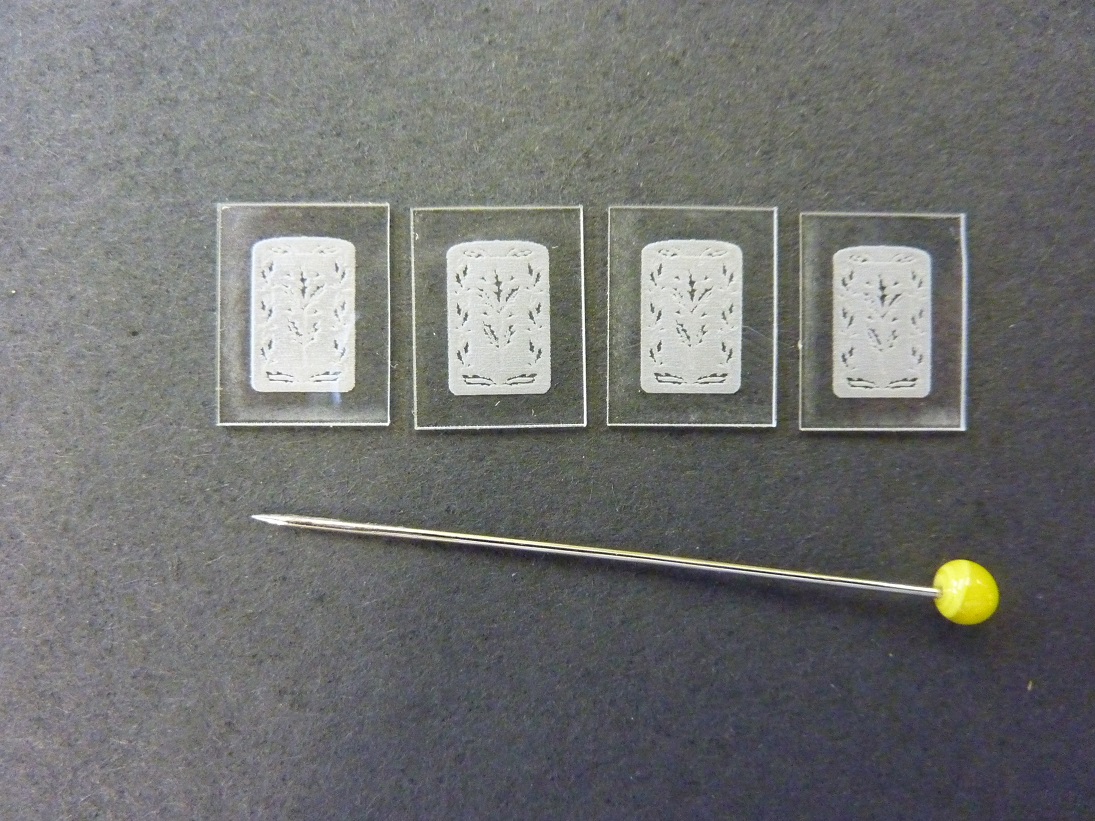
These are laser engraved on 1mm perspex and really lift the appearance of a Highland coach, as you can see:
Sadly, I have also had to increase the prices for most of the products. The costs of the last few deliveries from my etchers have been eyewateringly expensisve, so I need to defer a degree of this. The good news is that this is an indication that more products will soon be featured too – so Highland and LMS modellers keep an eye out.
Portchullin to Support Sutton’s Locomotive Works Class 25 Launch
Firstly I must apologise for such a long gap since my last post. As with many people, life, house moves, house extensions and children have got in the way a bit. So much so, I have to admit that I struggled a touch remembering how to log into my own blog!!
I have not been totally idle in the meantime and I do have things to show on the blog but first is an announcement of Portchullin’s next outing. It has been a long time since it has been out but there was a bit of a global pandemic that was largely to blame for this! This invite is a little different in that it is not a general model railway show but instead is to support a launch event for the Sutton Locomotive Work’s impending Sulzer class 25. This will take place in Crewe over the three days of Friday 29th Sept to Sunday 1st Oct, 2023.
In addition to seeing Portchullin, there will be two other excellent layouts there. The epic Mostyn from the Barrowmore Club and Underhill Yard by Dave Roome. The SLW team will be there too, along with the first production samples of thier new class 25 model.
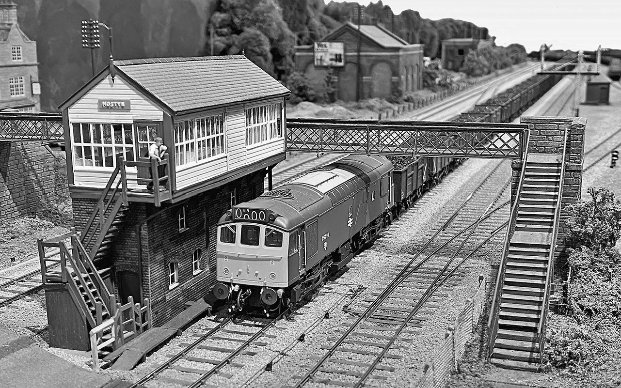
Mostyn
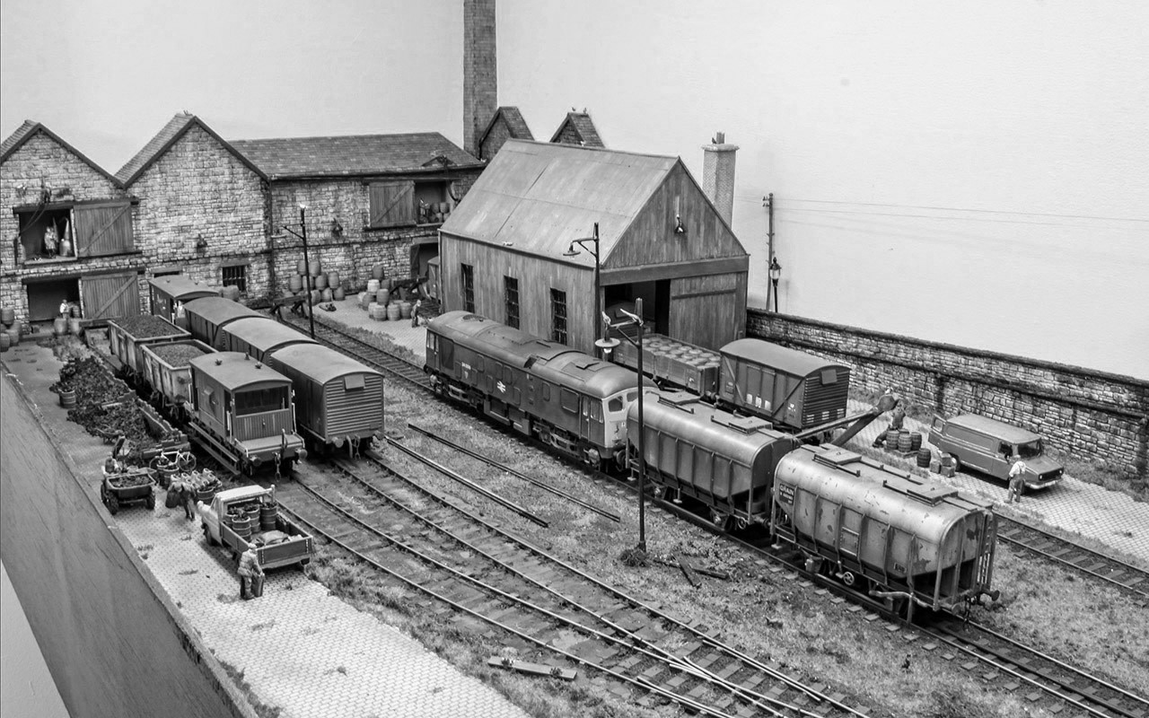
Underhill Yard
The event is for the customers of Sutton’s Locomotive Works and other selected guests that might be interest in good medelling and sulzer locomotives more generally. In this regard, if you are reading this blog you do count as a selected guest so are welcome to attend. However, please note that you need to book a visit and to ensure that the event is more relaxed than the average show.
Details of how to book can be found on the note of the show on the Scalefour Forum.

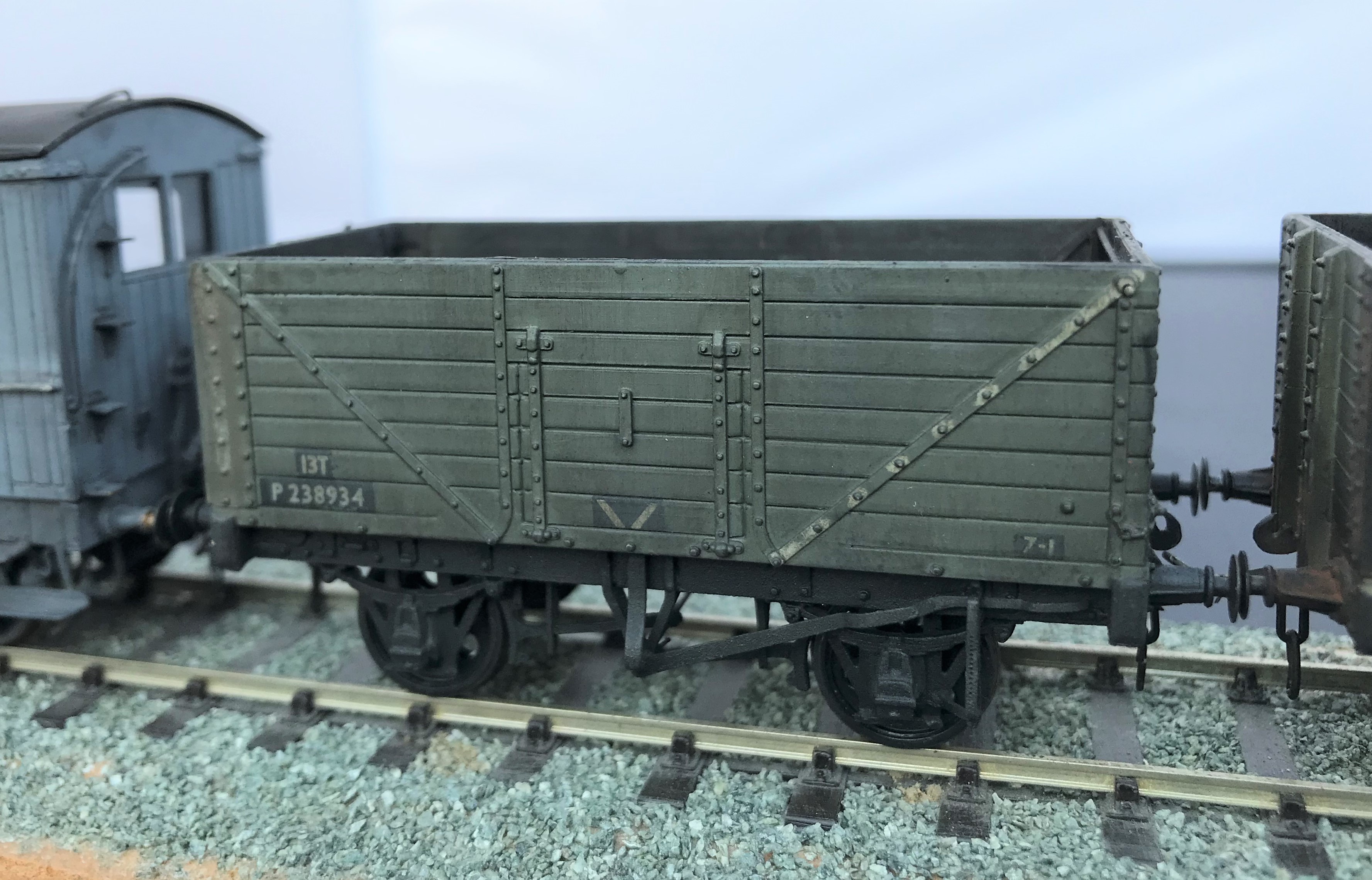
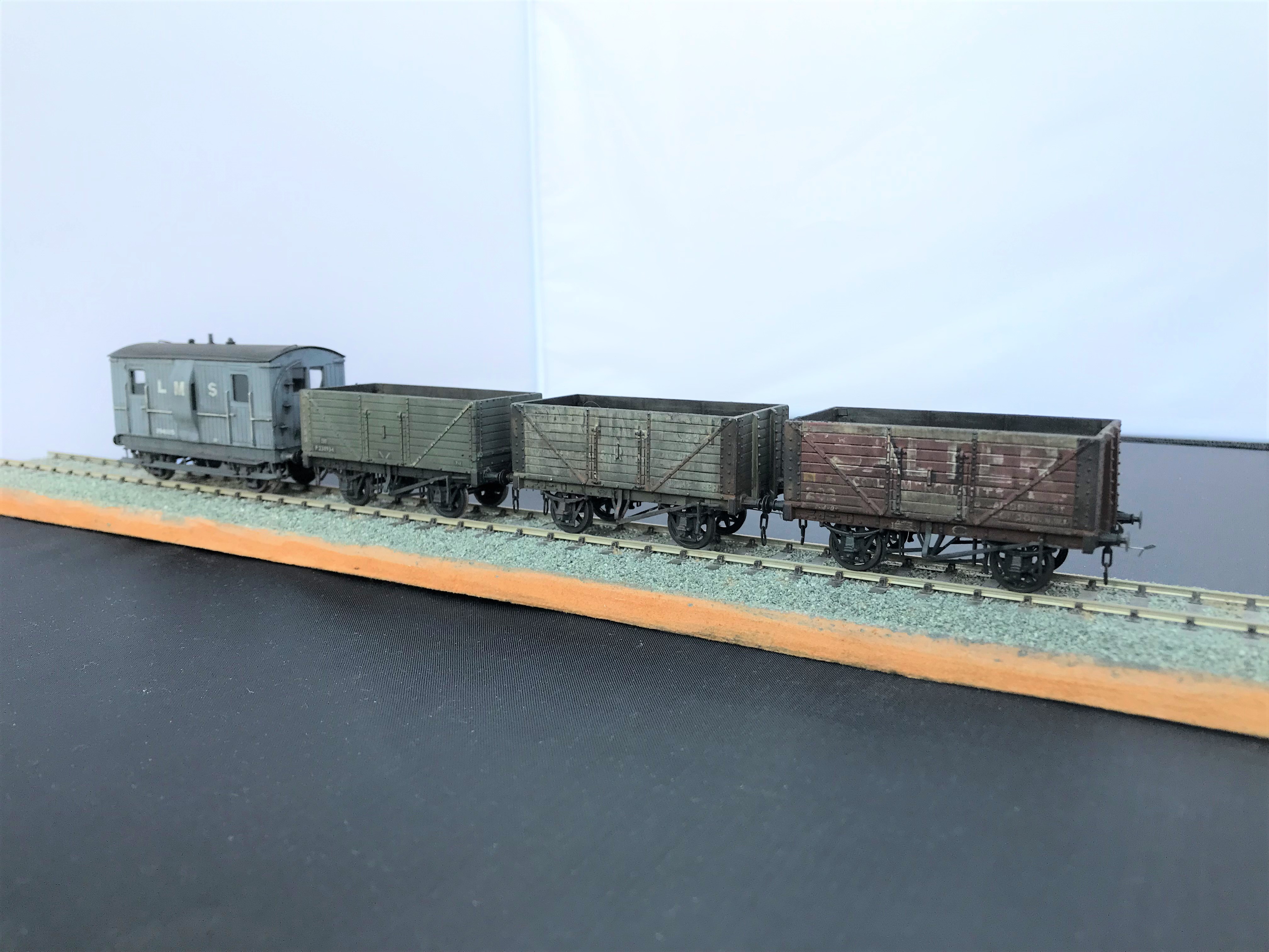
More Filthy Wagons
Weathering is not something that I find comes easily to me, especially where it needs to be subtle. However, what the OTCM lads have taught me is that unsubtle weathering is easier and a lot more fun! So I have been unsubtle and making a few POs filthy; I wanted to leave the impression that they have seen few decades of hard work and I am really pleased with the results.
All of these have origins in Bachman RTR minerals but with replacement chassis from Colin Welsh’s range (available via the Scalefour Stores – members only I think, so why not sign up!) and some replacement axleboxes from Rumney Models.
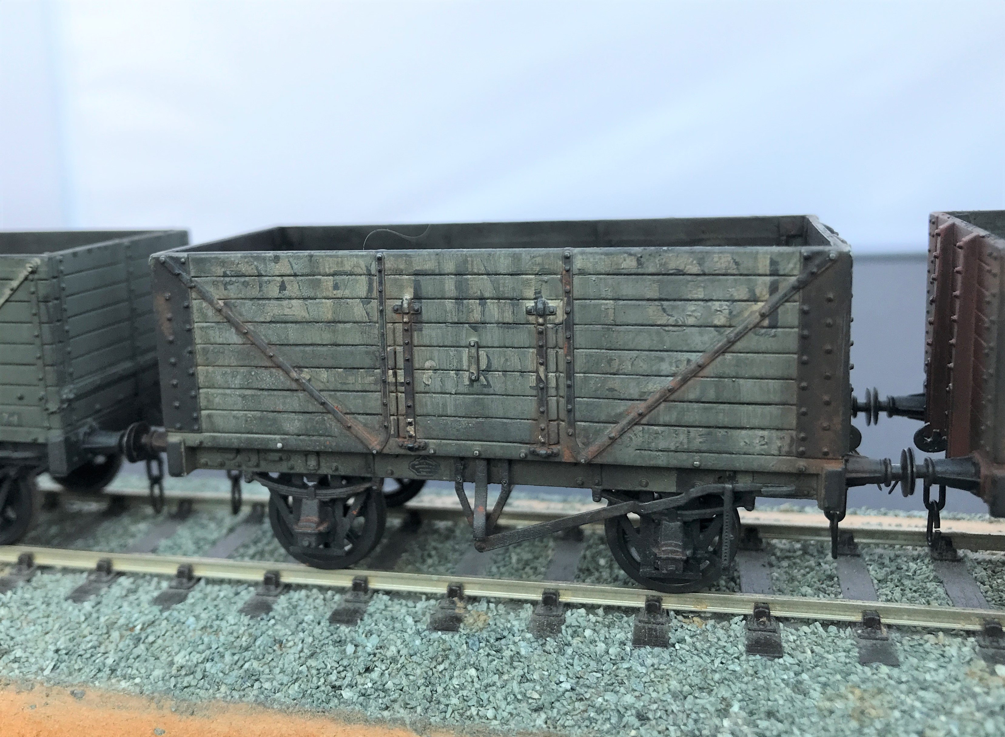
I started with the fibreglass brush to thin down the lettering to give it the feel that it is close to wasted away. Then I sought to represent plank replacements by painting out a few of these with a grey and then added a little texture with dry brushing with track colour (although ultimately the weathering was so heavy this subtly was not worth the effort). The same was undertaken to the insides of the wagon.
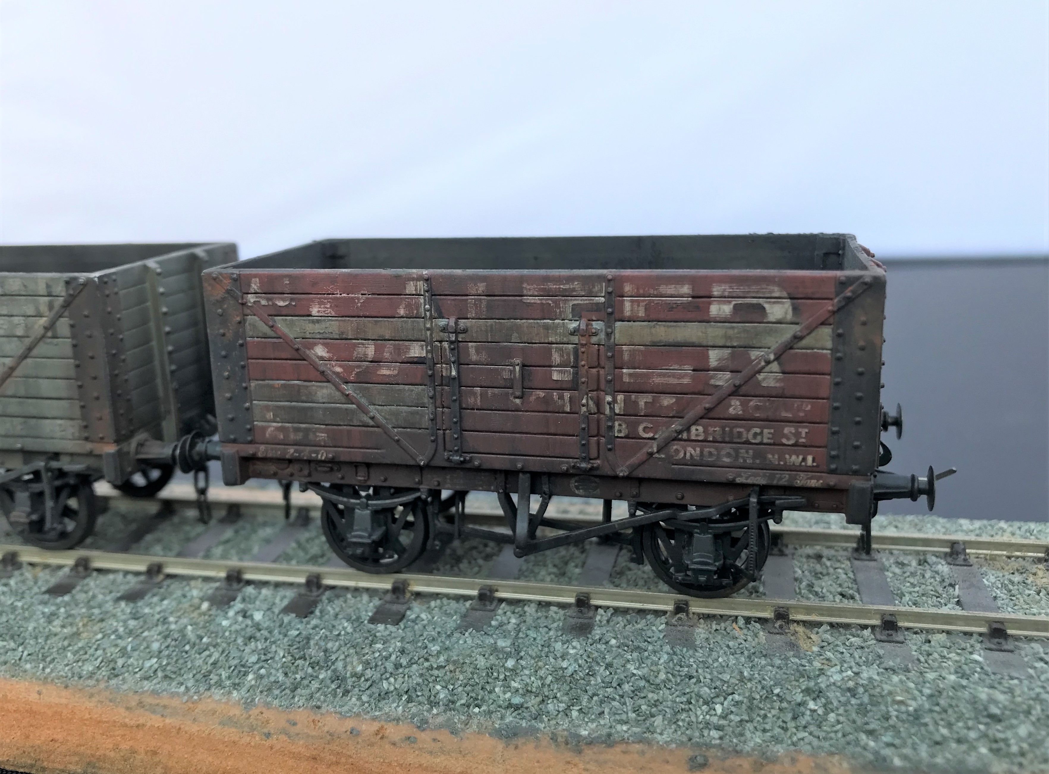
The weathering was completed by a mix of enamel paints; based on black and leather. I started with a lighter colour mix of 2:1 leather/black but then darkened this as I felt that a coal mineral would be a much darker mucky colour so reversed the proportions.
I did these over multiple coats under a very bright light, as otherwise you don’t really know whether you have put much paint on when it is deliberately so thin. The streaking is achieved by using a relatively large flat and stiff brush dipped in thinners. Don’t apply this straight into the model, rub it on the back of your hand to remove the bulk of the thinners and get it down to “slightly moist” before applying it to the model. Make sure it is drawn down vertically, to mimic the movements of water running down the wagon sides.
The final stage was then to use weathering powders, rust on the metalwork (mostly on the Partington grey wagon) and black soot. Very small amounts are put on the brush and then speckled on the model with the lightest of pressure because if you blob it straight on it tends to be rather heavy in the points of contact, so it gets a bit blotchy as a result. However, if this is the effect that is required – for example on the top of the buffers for me – then blob away! The powder is then spread across the model with the brush, the more pressure tends to deepen the colour but throughout the powders matt and draw together the underlying colours.
The coal effect in the interior was completed in a similar manner, but with a lot more powder is used and laid on the base a small amount coal dust secured on a matt varnish to leave the impression of a not quite well swept floor from the previous load.
The Other Benfieldside
To date, the images and details I have shown on Benfieldside have related to the main and original station. However, there is more!
Benfieldside’s original builder, John Wright, constructed a significant extension a few years after completing the core layout. This was shown at the time in the Model Railway Journal (issue 57, 1992) and has not really be seen since.
When John’s interests moved on, he disposed of both parts of the layout and in turn the new owner decided he did not wish to retain the whole. However, he elected to retain the extension in order to convert it to P4 as his home layout (Benfieldside was all constructed as an EM layout). We all know what life is like – jobs, family life and other priorities get in the way but progress is now being made. The two main lines are now operational, as these two videos show.
The new layout will be NER as a core, but with also a Midland presence. It appears that the Midland has provided the motive power for the test train!
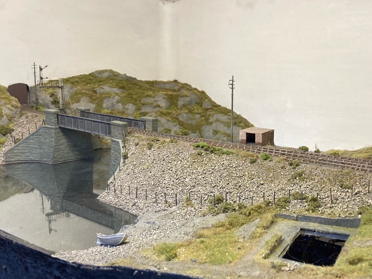
As you can see, Benfieldside’s extension was centred around a substantial viaduct with a degree of siding to one end. Its owner is proposing to make a small MPD here, the beginnings of which are visible in the videos.
There is still a way to go both in the adjustments around the MPD but also in refreshing the scenery. But never the less, as you can see it is another impressive layout.
Portchullin Goes Green………….Again
Fear not, this is not an announcement that the McRats have been converted from DCC to run on ethanol (although this remains the preferred fuel of the layout’s operators). Instead it is a recognition that after 13 years on the exhibition circuit, Portchullin was getting a little faded and even battered. The colours of the vegetation were fading and the woodwork was showing all the miles they have been lugged about in the back of a van – all in all it was looking like 1970s BR, just not in the right way.
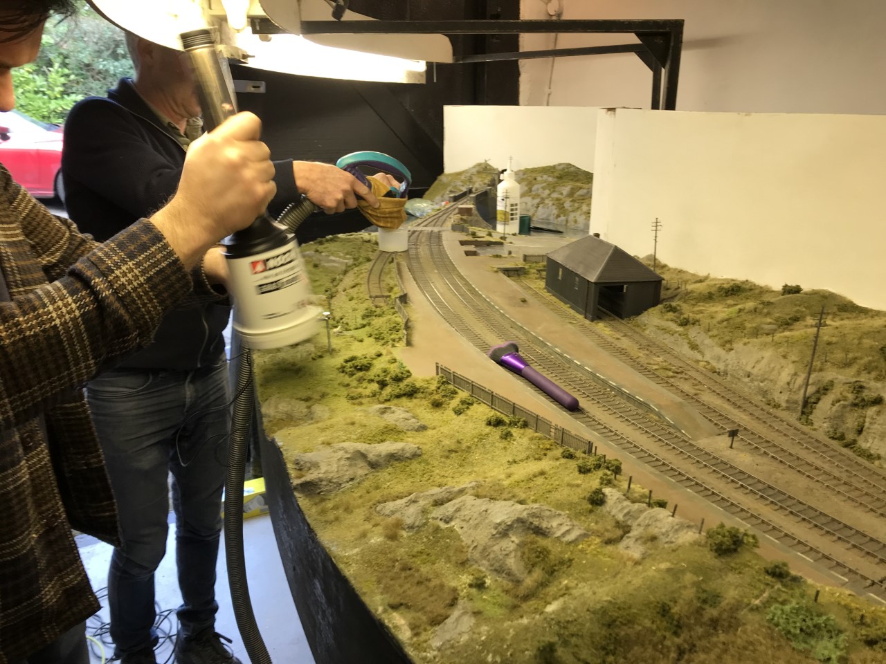
We reached the conclusion that something needed to be done about it and in anticipation of an April exhibition invite, the gang arranged a session on the layout to give it a spring refresh. Sadly the show had become a covid casualty by the time we met up but we convened anyway and even the stone-cold hearted Pete was showing emotion at seeing us all again by insisting on greeting us all with a hug!
So out came the static grass machine, modge podge and various scenic materials and away we went…….
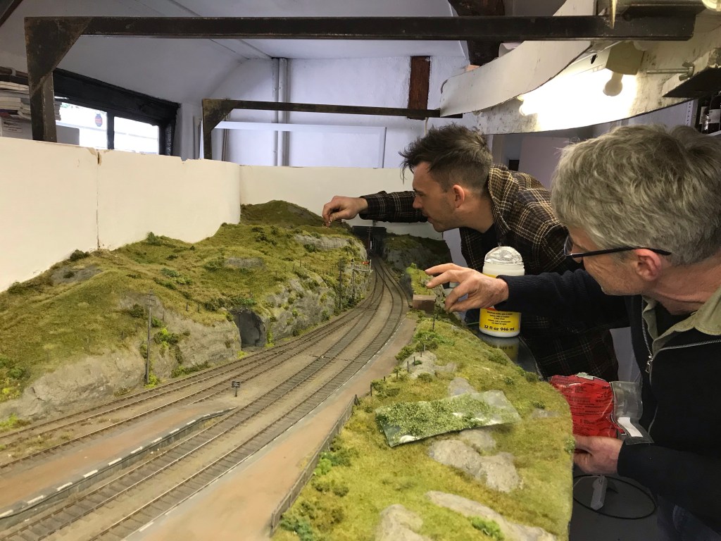
We ended up making quite a lot of difference in only a short while, but adding the dwarf bushes and other vegetation then took a lot of time and I am still thinking it needs more attention.
There remains a lot to do, including a revamp of all of the woodshell and lighting gantry, but the layout is looking a lot fresher.
The other main task in hand is a complete rewire. Too often we (well I, the others will have nothing to do with my wiring) have had heads under the baseboard trying to sort out either point-motors or errant wiring, it has to change!
The Other Auto-coach
Some time back I posted about the construction of a NER autocoach that I was building for Benfieldside and subsequently what it looked like once painted by Warren Heywood.
The NER generally used these in pairs, with a loco sandwiched between, although they did go out singly and even as quads. In this case, the Benfieldside team wish to operate them as a pair, as the bay to the right of the layout is conceived to receive such a train, with a NER / LNER G6 in between. This means that there was pressure to build the second from the moment I handed the first over. They have recently given me a favour, so it was high time I repaid it.
It is now completed down to the final check over stage (which has indicated that I need to put the steam heating pipes on – doh!) and then it can be delivered. So I have braved the fading light this afternoon (so sorry about some of the depth of field issues) to take a few pictures and to prove to the fellas it is done!

I completed a few personal upgrades to the kit in both this and the earlier autocoach. Chief of these is around the roof where I ditched the plastic roof and replaced it with rolled brass. This was formed of 0.25mm to give it a tangible depth, which makes its rolling a fair challenge. Add to this, I elected to cut out the portion below the clerestory, so that it was a clerestory! By the time I had added the gas lines and the various gas lamps and ventilators, I reckon there is around 20 hours in making the roof alone!
The prototype coaches were fairly long lived and numerous. They thus collected a good number of alterations and differences over time. I took some guidance to David Addyman and tweaked the kit in respect of gas lines, foot steps, handrails, footboards and gas cylinders. If someone thinks this is wrong, please don’t tell me!!
It always amuses me that the driver had to stand and peer down the line through two tiny windows. They lived in different times – could you imagine the snow-flakes tolerating this in the 21st century?
These are rather beautiful coaches, but not for the feint-hearted as there is a lot of time invested in these. I am pleased I do not have to paint it!
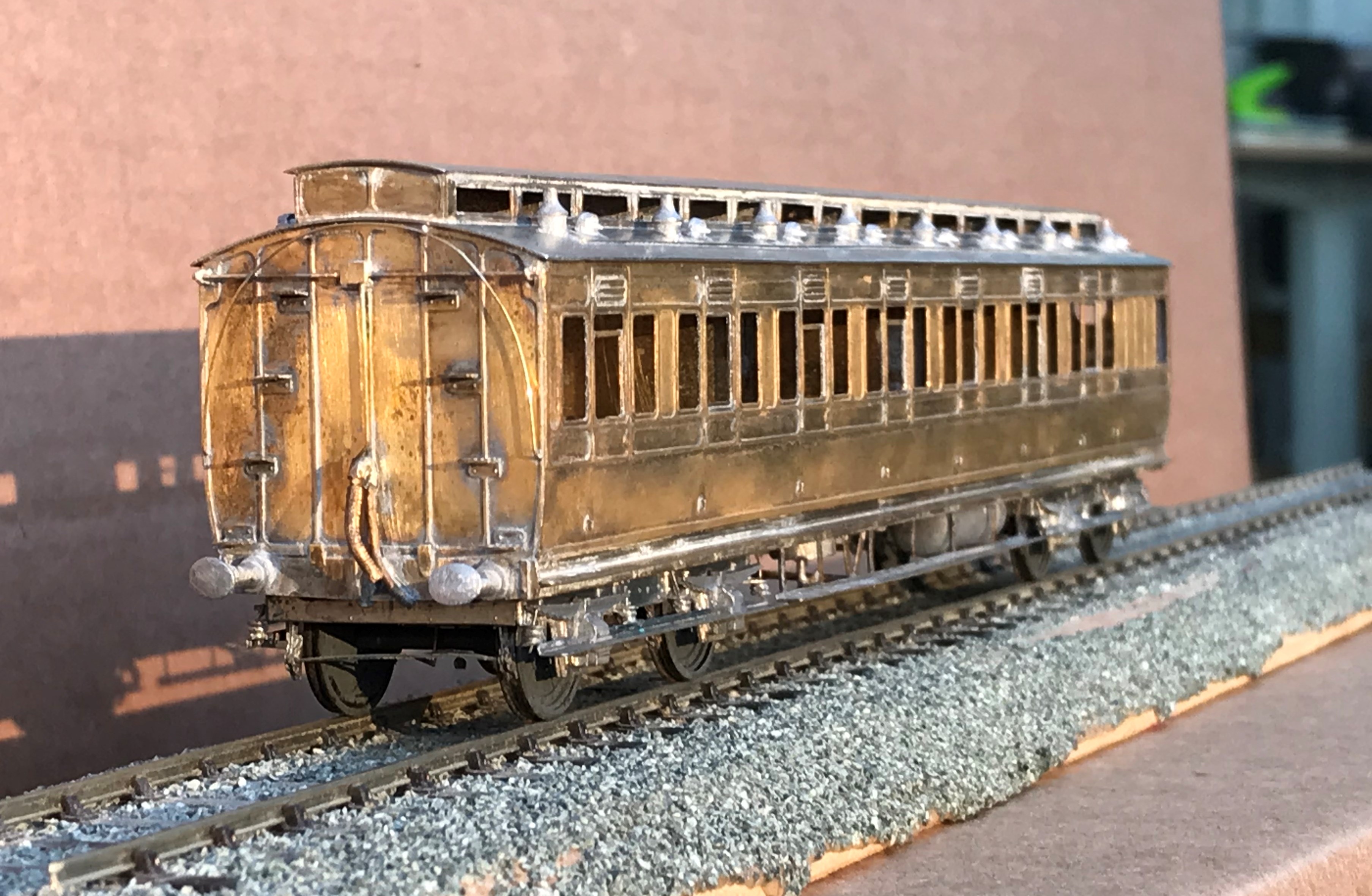

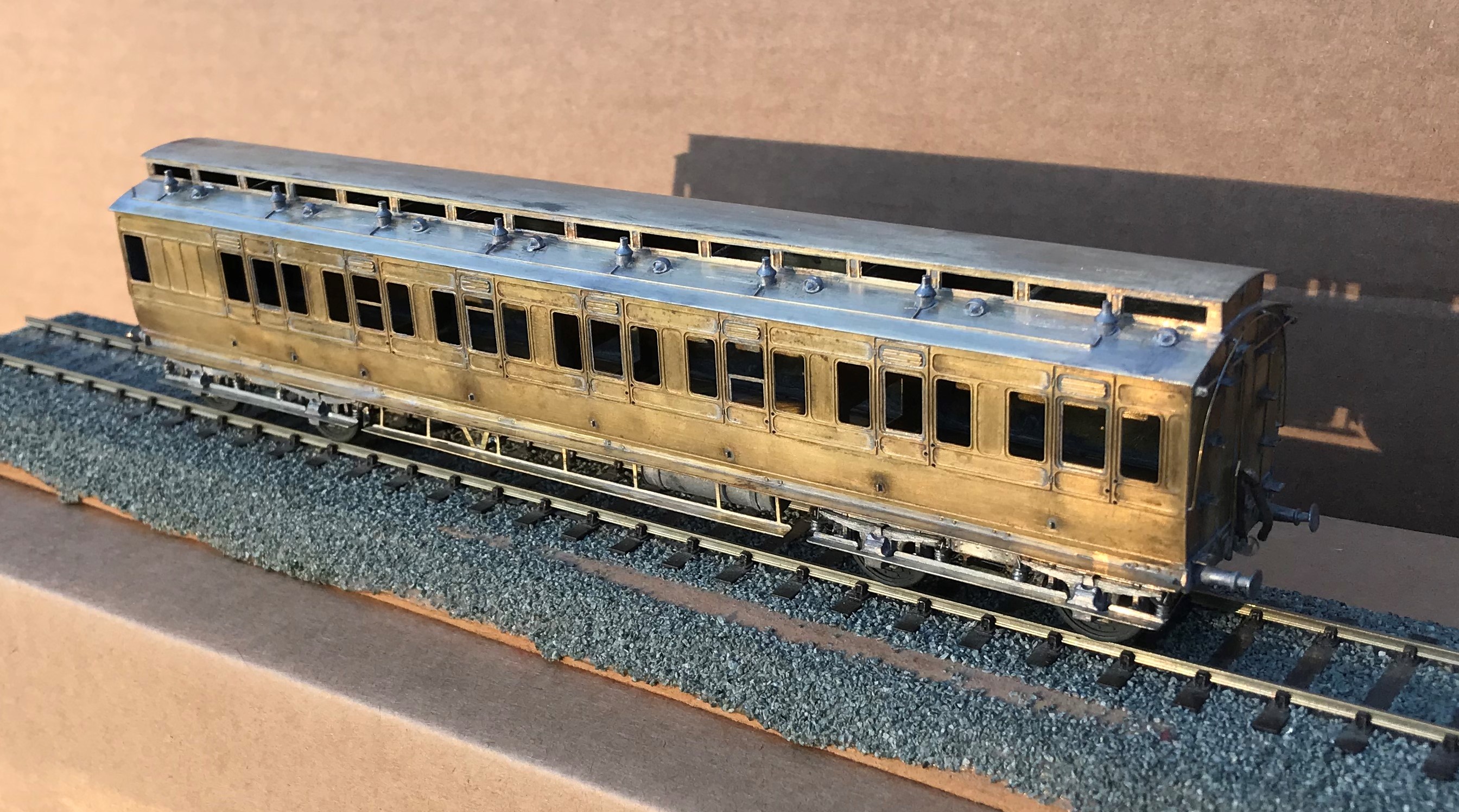
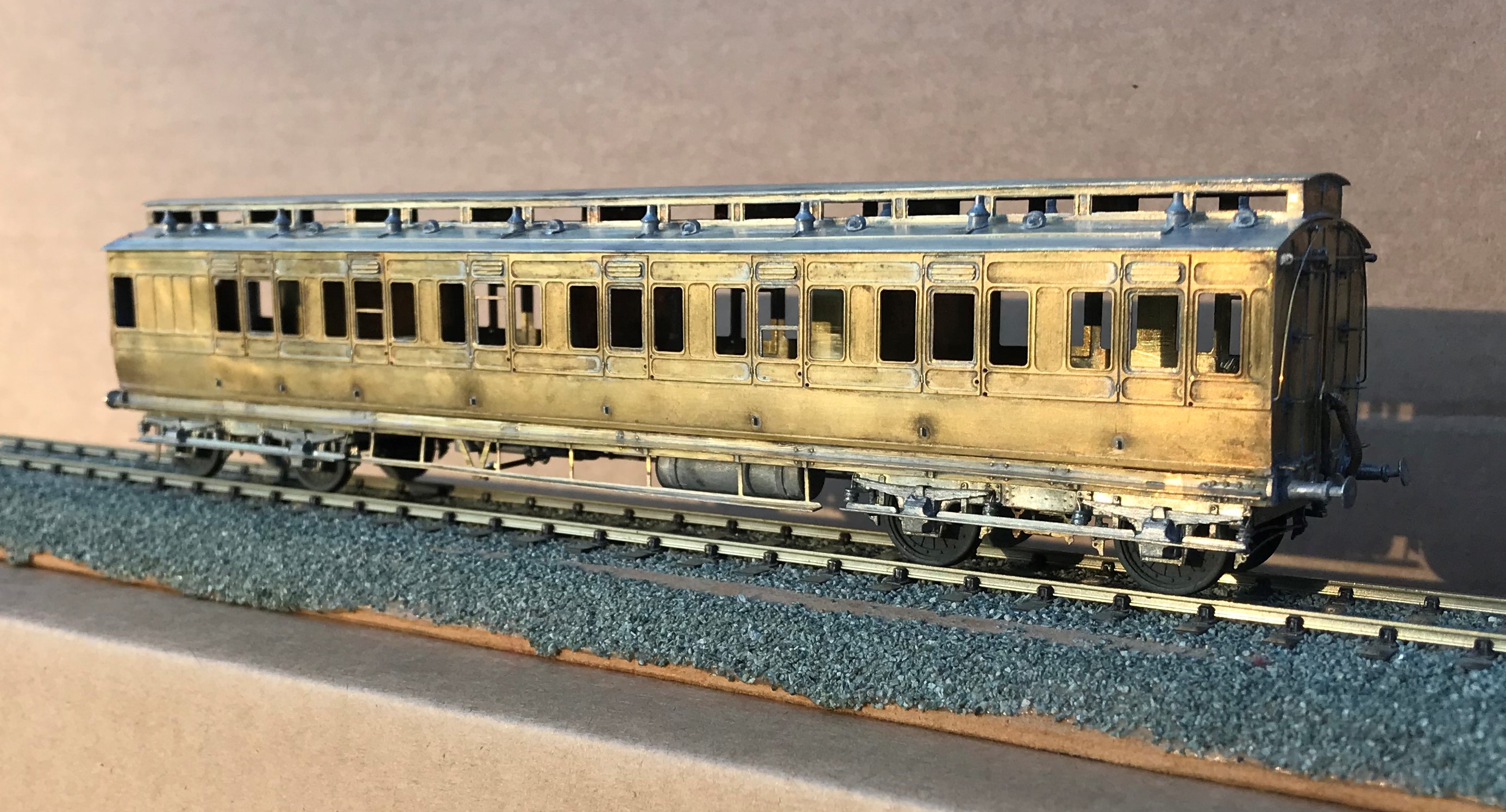
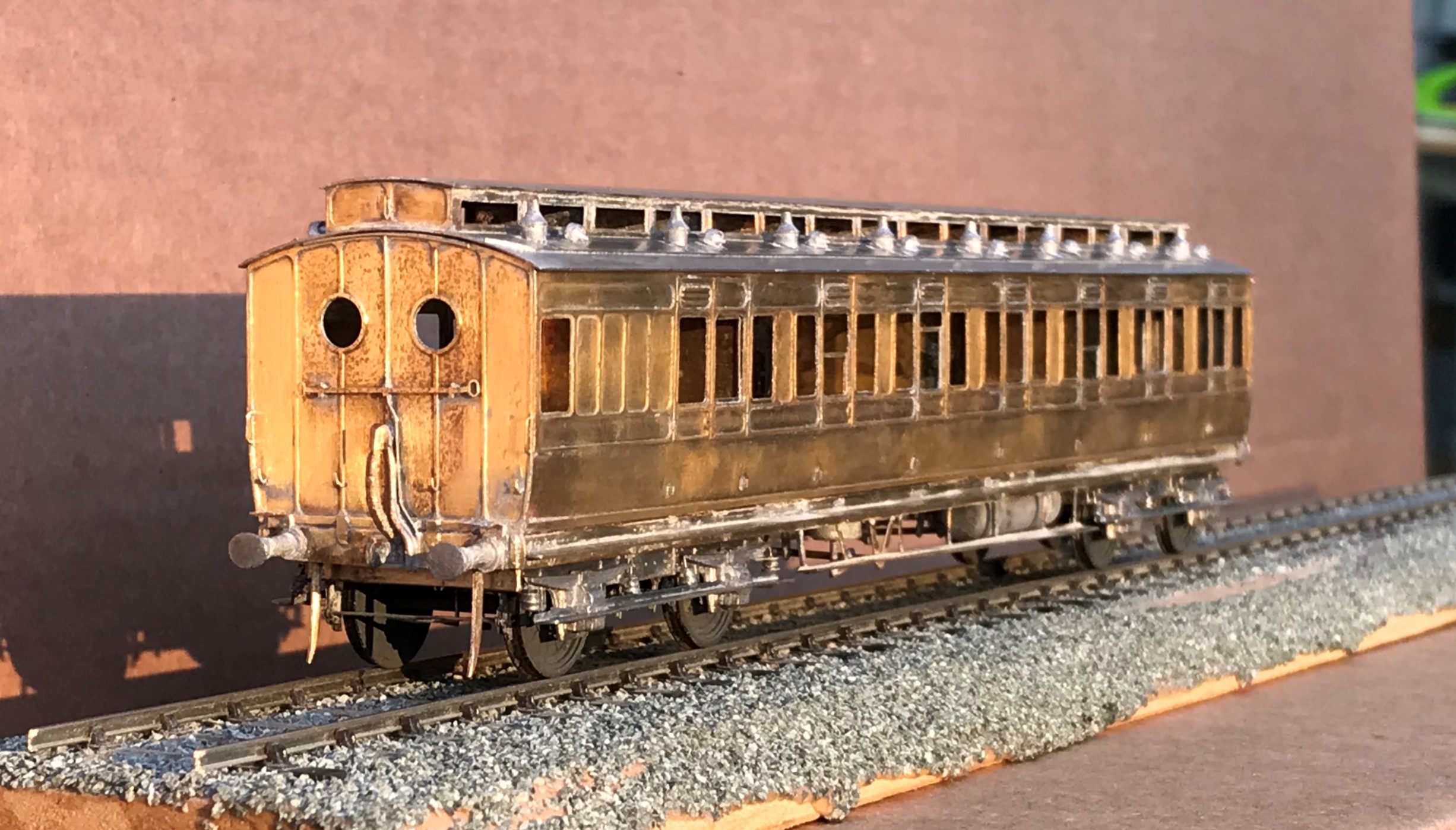
The Polytechnic Special Excursion Train
From time to time, I see photographs that are intriguing or catch the imagination. This week generated one such example that I felt was worth sharing. In addition to being a rather wonderful timepiece of Edwardian travel, this view of a Highland Railway series 1 castle on the viaduct at Killiecrankie prompts a number of interesting discussion points.
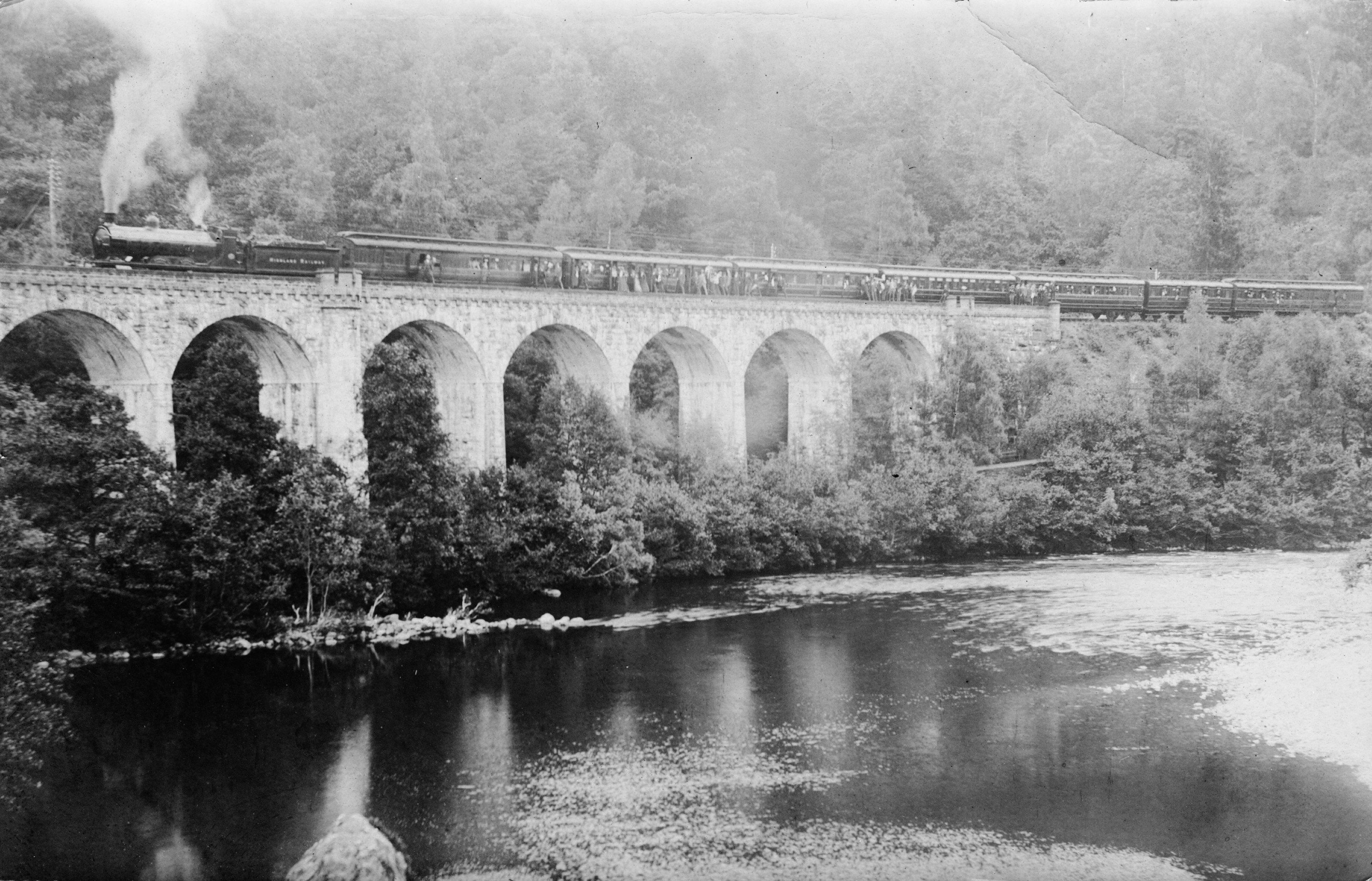
Dealing with the purely railway one first; the constitution of the train. This is largely made up of East Coast Joint Stock coaches from the early part of the last century, supplemented by a Great Northern dining car and one NER coach. The East Coast Joint Stock Co was a joint undertaking of the three companies that made up the east coast route from Kings Cross to Scotland to provide coaching stock that could run across three company’s lines. Back in 2016, I showed my part build of a very similar coach to those on the viaduct for you to compare. By the way, before long there will be a further instalment in this series, as I have made progress with it and have a pretty much finished coach.
What initially surprised me was that all of the stock was third class; which was very unusual for trains of this time when railway travel was proportionally much more expensive and thus attracted the “monied classes” rather more than today. My colleagues in the Highland Railway Society of course not only had the answer for this but there was even an article on it in their journal a few years back written by John Roake. The train is obviously a special rather than a day to day timetabled service and it transpires that it was one of a series organised by the Polytechnic Touring Association in the beginning of the 20th century. This organisation had its origins as a travel society of the Regent Street Polytechnic (which has developed into the University of Westminster) who arranged tours within the UK, Europe and further afield for its students before subsequently becoming and independent business in its own right. In time, it became a fully fledged travel business and once it had merged with a firm called Sir Henry Lunn Ltd, became a household name to people of my generation – Lunn Poly (now part of Tui).
From around 1901 rail tours of the Scottish highlands were organised in specially commissioned services across the summer season. These were advertised as “a week in bonny Scotland for three guineas“. This was equivalent to a month’s average wage at the time, so even though the service was not in luxurious first class, it was hardly for the masses either. This is rather evidenced by the finery of both the ladies and gentlemen that are visible in the picture. The tour visited a number of Scottish beauty spots, often combined with a steamer trip to complete a round circuit or, as in this case a walk through the scenery to Dunkeld. Dunkeld is 16 miles from Killiecrankie, so they got a fair share of exercise!
The picture is a posed shot and is likely to be an official view for publicity purposes and what caught my eye was the participants standing on the viaduct’s parapet. The viaduct is 54 feet high, so these people are standing about seven stories up on an ledge that is a foot or so wide! Can you imagine the health and safety police sanctioning that now? Mind you, when you look closely at the picture you can see that many of them are leaning gingerly back on the carriage stock – so it appears that they were not oblivious of the fall!
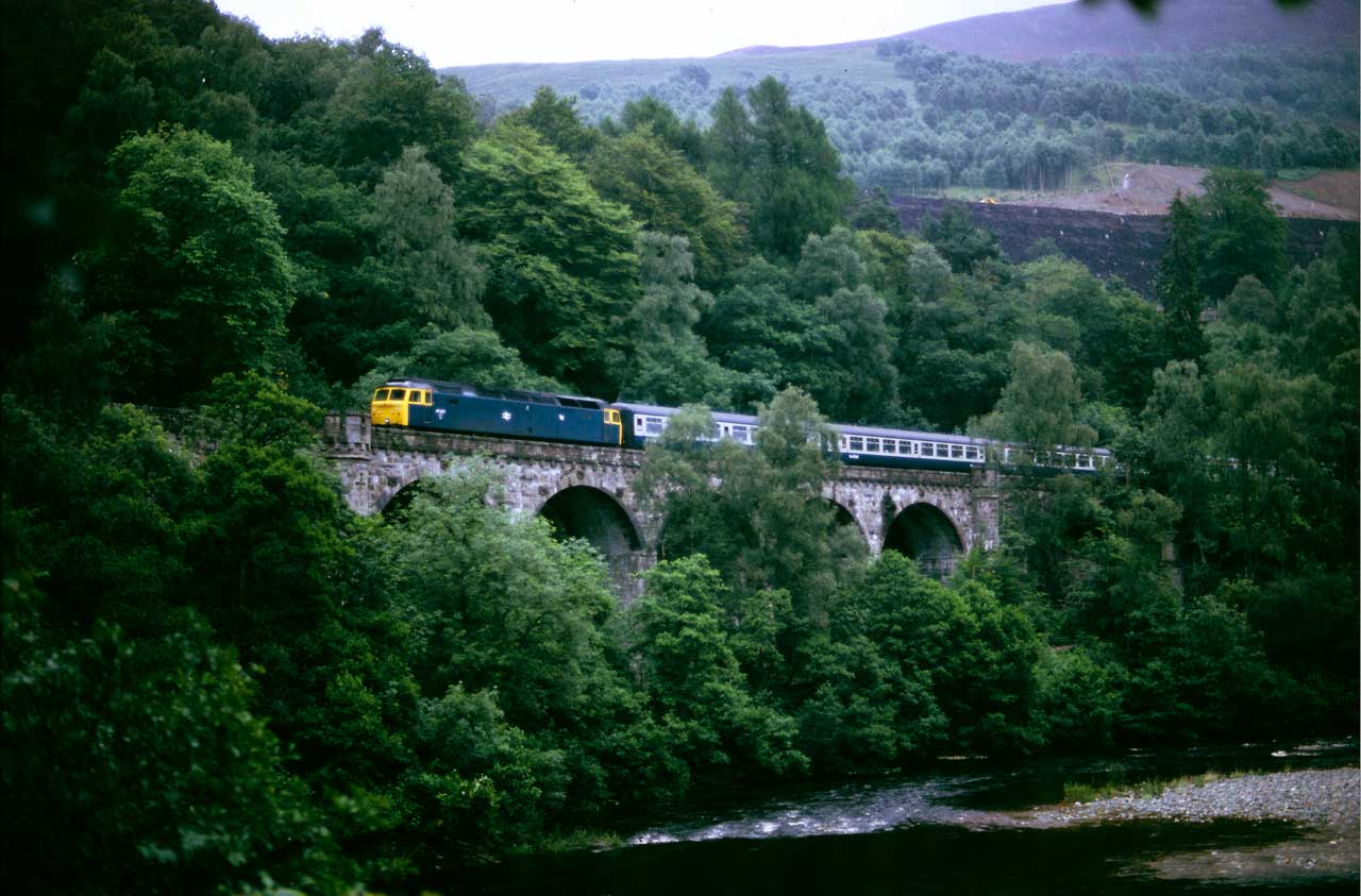
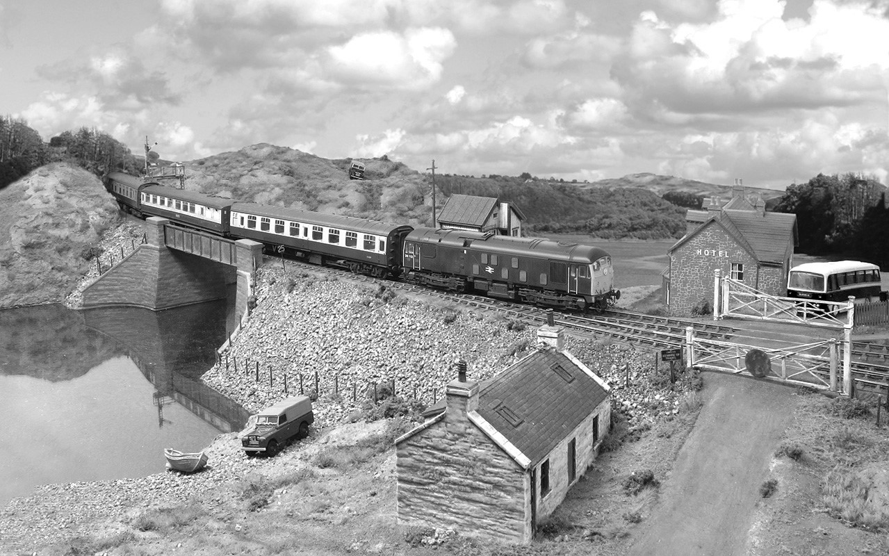
And to sign off, this is an image from about the same place approximately 80 years later in July 1985; a class 47 on what is probably the northbound Clansman service from London Euston (photo by Eastwood 4117). The trees have gown up somewhat in the intervening years – as they have since, the view is largely obscured now but the walk along the river is still worthwhile if you are in the area.