Blog Archives

Scrap Tank Test Build – Part 7; Boiler Assembly and Finishing the Cab
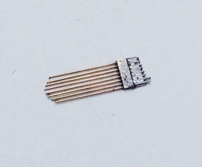
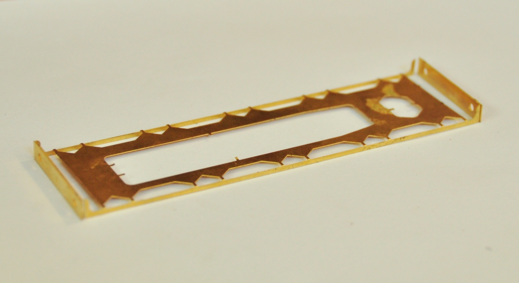
Next up is the finishing of the detailing of the cab. Common with many tank engines there were grilles over the rear windows. For these, I toyed with the idea of doing these as a single etch, a bit like the Mainly Trains one (and possibly others) but elected instead that the slight roundness of the bars needed to be captured, so this meant that brass rods were going to be required. If I had either etched small holes or soldered these on top of the cab etch, I felt that getting consistency of spacing was unlikely and that this would detract from the finished effect. Thus, it was time for a little jig.
This jig is simply a sheet of brass with holes for the wire at the appropriate spacings along with half etched lines arranged such that when the jig is folded over, the wire is trapped between them. This is what it looks like with the wire in and the jig folded over (along with a dab of solder to hold it all still):
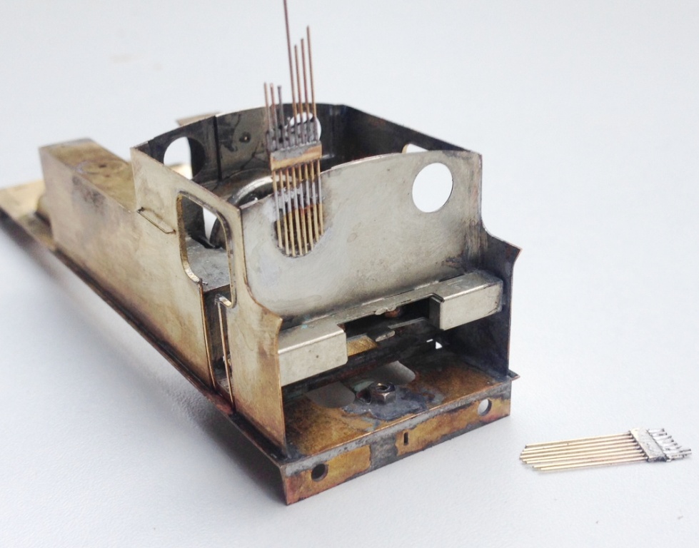
You will note that in the picture above, I have trimmed the wire rods to a gentle curve to reflect the curve of the spectacle plate and in the picture below, this has been soldered on the ring around the window. The jig is then snipped off and the rods can be cut away. I found that by using a scalpel, it was possible to cut a nick in the rods and then the wire could be carefully lifts so that it snapped at the point of the nick. It was necessary to ensure that the rods were soldered well to the sides as if this joint failed it was then pretty difficult to get them soldered back down neatly; I will include a space jig in the production etch of the kit to give the user a second chance!
There is also a beading around the cab side openings, a common feature on pre-grouping locomotives. This was relatively simple to fit, although I did make it a tad too fat deliberately to assist in the process – it can then be filled back to a thinner dimension and in the process any slight irregularities taken away in the filing. In this example the stanchions are probably a bit far away from the cab sheets, so there will be a slight adjustment on the final version.
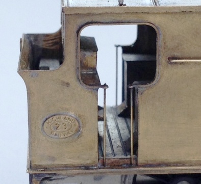
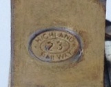
Also worthy of note is the cabside number plate, which I am dead chuffed with. This is a cruel enlargement as the whole plate is only 6mm across and to clearly be able to read the text which is only 0.7mm high is pretty good I reckon!
After finishing the cab detailing, it was time to add the boiler onto the tanks/running plate and she is beginning to look like the real thing, although perhaps looking a little naked due to the missing dome and chimney at present!
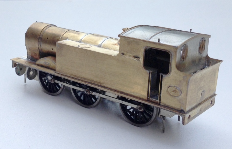
I have fitted a safety valve bonnet and safety valves from those intended for the Strath/Loch and available from Lochgorm Models. I also formed the front splashers, which I had tried to make easier by the use of some tabs and formers. These did assist in the assembly but I then found that they fouled with the wheels, as I had made the splashers true to scale and the tolerances did not allow for the tabs. I will have another think here and might come up with a jig, as splashers are sometimes a bit painful to fit.
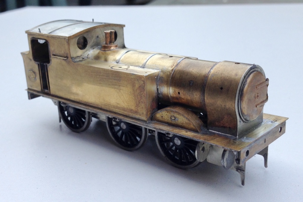
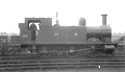
And this is what she presently looks like; definitely beginning to look like the real thing (a reminder of which is below). For those of you that are coming to Scalefour North I will bring her along for you to have a look at. As we are now about up to date with her construction (you didn’t think I can build that quickly did you?!?!) and because I am away the whole of this weekend at Scalefour North, there will be a hiatus a bit before the next posting.
Scrap Tank Test Build – Part 6; Boiler and Running Plate
Now that the much of the bulk of the above running plate work has been completed, the running plate valences can be fitted. As these are nearly always long and thin, they are prone to distortion in the kits I have built – so it is time for another jig!! This one holds the valences at numerous places to stop it flexing and to hold it straight.
With this, it is a doddle to fit the valences in their correct place and solder them without distortion. I did find that the running plate flexed significantly at the end of the tanks; so the final version is going to include a pair of temporary stiffeners that fold down and stop this. This would be the moment when they are removed to allow the valancing to take their place.
And onto the boiler. In a departure from normal practise, I am not including a flat etch to be rolled into a boiler – it is relatively difficult to get even a pre-rolled boiler into a neat tube without a visible seam and if you do not have a rolling machine it is effectively impossible to do so. In addition, where boilers have been half etched to create boiler bands I find that the half etched elements that remain are overly delicate. This was something that caught me out a while back when I drilled such and area to take handrail knobs and badly distorted the metal – this kit is still sitting in its box now and I am probably going to have to replace the boiler.
With these problems in mind, I simply used a piece of brass tube from Eileens; easier and much more durable and if I were sratch-building I would not even think of taking a different route. This did still leave the need for some rolled parts, to make the smokebox and I have sought to use another little trick here to make these easier to fit – some tags and eyes. The tags are strips of half etching that pass through the eyes and then tugged back. This can’t impart a curve into the metal but does allow the parts to be pulled tight and makes it easier to solder into place without much of lip. Mind you, they were a tad short and will be lengthened slightly in the production run.
A second additional laminate is then needed to form the outside of the smokebox and down onto the saddle.
I did find another little error when it came to the front of the smokebox. Whilst the diameter for the front that I had drawn had allowed for the thickness of the two laminates, when you fit these there is also a layer of solder between them and whilst this ought not be that thick, it was just enough to make the fronts too small. In the production run, I will deliberately make this a tad too big as it is easy enough to file it back but much more difficult to add the missing metal (I didn’t, I just made a fresh one from sheet metal). The smokebox door is not mine, the door from the Lochgorm Models Loch is the right size judging by the photographs (note the drawing in the old man’s book has it being smaller but this does not match the photos, so I ignored it in this respect – sorry Dad!).
The downside of using tube as a boiler is that boiler bands need to be considered. I have provided these in the kit (again using the strap and eye technique). I chose to fit them on this kit although in practise I think any metal boiler band is too thick and would probably have done it with a transfer sheet if this was not a test build (done prior to painting, the thickness of the transfer is enough to show through the paint on what will be a single colour to the boiler).
Only the top of the boiler is visible after the first ring and a bit, so can be cut away to leave lots of room for the motor, weighting and DCC chip. I may try and fit this with sound, so who can give a view on what it might have sounded like – a jinty is my favoured guess?

Scrap Tank Test Build 5 – Getting on with the Chassis
With the basic chassis made, it is essential to fit the nuts to secure the body to the chassis as both of these will be concealed with later work. So a quick test fit looks like this and we can get onto the next bit, the coupling rods. 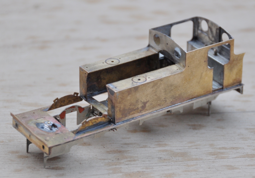
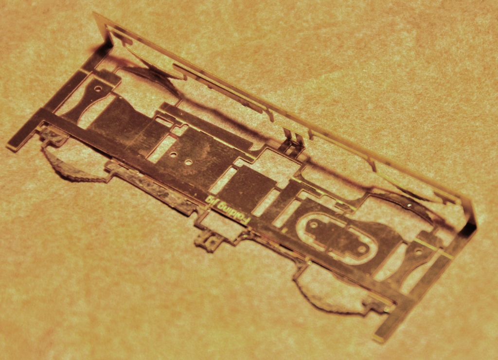
As is not uncommon, these are made from a pair of layers of brass laminated together. You can see that the outer layer is half etched for much of its length, with the full depth only being present at the bosses. I have also sought to make it easier to build these by including them in a folding jig – the folding is underway in the bottom portion of the view. The logic of the jig, indeed the whole kit, is to make a really smoothly running chassis much easier to make. Modern CAD and computer operated phototool creation techniques by the etchers means that it is possible to easily draw and then etch such that each dimension is faithfully repeated on the product. Thus, it is possible to be confident that the wheelbase will be repeated exactly on each side of the frames and also on the coupling rods. However, this accuracy is completely lost if the user has to laminate the two parts together by hand; it is not possible to get them superimposed on each other exactly or repetitively so the spacings of the crankpin holes will change. The jig overcomes this as the fold line is so long that there can not be any twist as it folds, so the two parts will meet consistently and accurately. 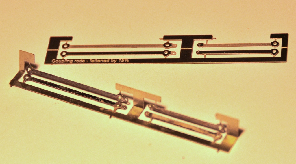
It is true that there remain two areas of variability. The first is that the degree of etching will not be exact on every occasion so the holes will be slightly bigger or smaller on each occasion. This can be easily overcome by making all critical holes a tiny bit too small and then opening the holes up with a ream (not a file, reams will open up a hole consistently). The second problem is that a fold is not always consistent on a fold line so the jig can protect against twisting but might not necessarily put the two laminates directly on top of each other. However, the important point is is that they will be correct horizontally, any error can only crop up vertically. Thus, when the crankpin whole is opened up, it is possible that it will move vertically slightly but this will not change the dimension between the holes so the critical dimensions should be retained perfectly.
The above is all true in theory but in practise there was an almighty cock up in my artwork; so I was deprived of finding out. A total case of designer error and when this is yourself, there is no one else to blame………………. 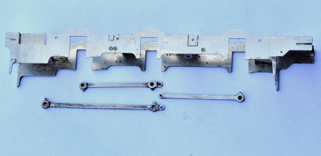
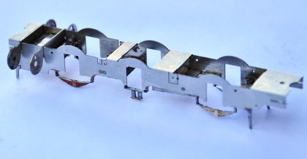
………..I made one of the coupling rods no less than 8mm too long – doh! I have no idea how, but it needed chopping; so it was back to the old fashioned way of making coupling rods despite my high ideals! Fortunately, as they were laminated, it is possible to stagger the cut to make the splice – essentially the same technique as Alan Gibson’s variable length coupling rods. Anyway, after the cutting and splicing, I did get a sweetly running chassis and this is what it looks like. The unusually large wheels for a shunting loco are already making their presence felt! 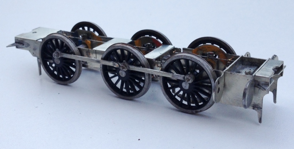
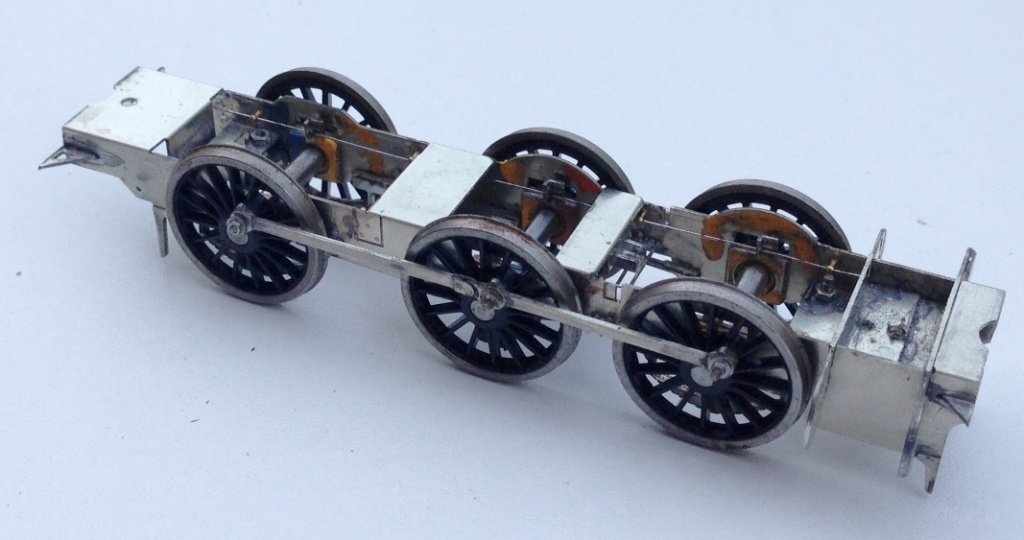
The chassis is created around CSB’s; continuous springy beams. A spring wire is anchored to the chassis at four points per side (for an 0-6-0) and at the centre of each hornblock. Thus each hornblock is supported on either side and can “bounce” on the spring. However, the clever thing about CSBs is that when a hornblock is depressed, not only does the spring wire flex a bit as suspension, but it also rocks on the anchors so the adjacent wheels push downwards a bit to equalise out some of the deflection. It produces a really smooth chassis and, if it is conceived at the design stage, I think is actually rather easier to both design and build than traditional compensation. This is a close up of a pair of hornblocks and a pair of the anchor points (the other is hiding behind the frame spacer on the right). Also worthy of note is the colour coding of the hornblocks; to enable them to be reinstated in the same hornguide each time. This is probably unnecessary with modern (and therefore consistent) hornblocks and the accuracy of the etching I have noted but old habits die hard! 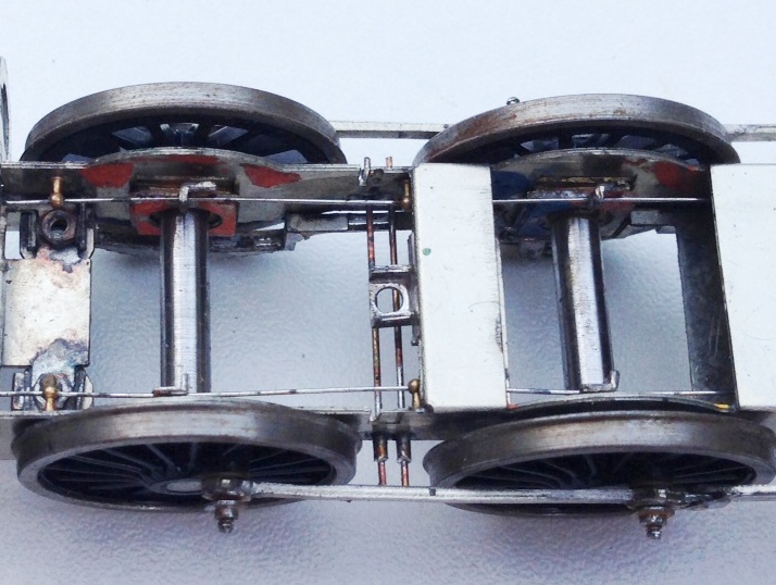

Scrap Tank Test Build – Part 4; Beginning the Chassis
Putting aside the body for a while, to take a look at the chassis because it is necessary to mount the two together and it is not possible to close up some of the element of the body until this is sorted out.
As with the body, I am trying to take a moderately fresh approach to the chassis to make this a little easier to build than certainly most of the kits I am used to. In this regard, most of the kits for the Highland are quite traditional in their design and I readily admit that all but two of my ideas has been either all out pinched from other designers or at least significantly inspired by them. All I am trying to do is use more of these neat ideas in a single kit to make the life of the builder easier. I am, however, finding that it makes my life more difficult, as there are a lot more moving parts to most components, so more places for the tolerances to be catered for; so as John Price has already said, the list of little tweeks and amendments to make is growing! At least, no one can say this particular kit designer has not built their own model.
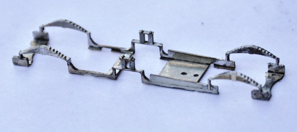
Anyway, this is what the chassis looks like in the flat; note that it is a fold up design – this is inspired by the Mousa Models chassis, so a pinched idea!
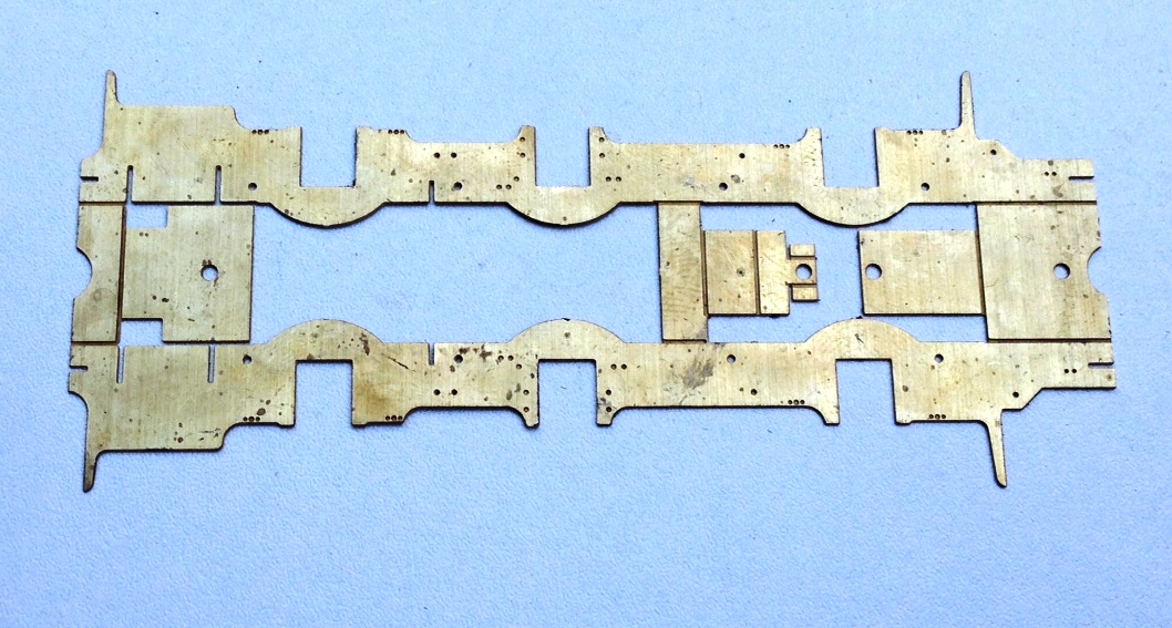
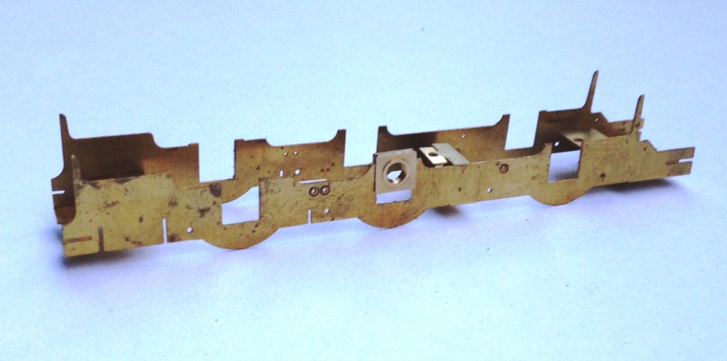
And this is what it looks like with the basic folds made up. What it achieves is really neat, as it is instantly sufficiently stiff to work as a chassis; by the time a couple of further cross braces have been installed the basic chassis is more than robust enough for its life.
My design uses the same slide in hornblocks as utilised by Comet and Brassmasters for their chassis. After a tiny bit of practise, it is possible to size the hole for the hornguides such that these are just too small when etched. This means that with a few strokes of a light cut file on each side, the hornblock becomes a tight sliding fit. Once all of the hornblocks are in, it is then possible to measure the distance between each on both sides of the chassis and also on the corresponding coupling rod. This is done with digital callipers and by the expediency of measuring the distance at its maximum with the callipers facing outwards and then repeating with them facing inwards the average being the actual distance between the centres. I reckon to be able to measure down to 2 or 3 hundredths of a mm, which is rather better than I can build to! Where there are inconsistences, this is dealt with by a few more strokes of the file on the side which needs to be adjusted to change the centre. This needs to be done anyway to turn the tight sliding fit to a snug but smooth fit for the hornblocks to work properly soif the centre does not need to be changed, the file strokes are undertaken equally on both sides of the hornguides.
This does need to be done after the coupling rods have been formed, of which we will see in the next posting. However, the chassis is also designed with a keeper plate to accommodate all of the cosmetic springing to the model and the ashpan sides. This is secured with a series of 12BA screws to enable it to be removed to allow the wheels/axles to be dropped out. A great boon as the model is built and painted.
To make the assembly of this element easier (in fact in this case a lot easier!) I have created a jig that holds the two layers of the laminate in exactly the right position. The jig is chunky enough to avoid distortion as it is folded up and it locates the parts perfectly. In this particular case, the soldering needs to be done with care as there are folds to make after the jig is cut away and it is important not to fill this with solder before hand.
And this is what the keeper plate looks like – it is pretty delicate until it is mounted but fine thereafter.
And the two components assembled look like this. The beginnings of the cylinders are also visible, this is a slide in module that can be removed for assembly and painting (although the scrap tanks were painted fairly simply, so this is not really relevant on this model).
No Point Hanging Around
Whilst I have not put any posts up showing progress with the boards for Glenmutchkin, progress is being made and the last two boards are essentially now finished. I am hoping that with one more day’s work which will mostly be to build up a carrying box for the final two, they can all come home.
In anticipation of this, I have been building some turnouts and a bit of the basic trackwork.
I am only able to do the turnouts which I am reasonably confident will not change shape when the track is finally laid out on the boards. In essence this means the crossings in the bay, the main line and the goods yard. I have also done one of the turnouts in the yard. So seven down, twelve to go including a slip!
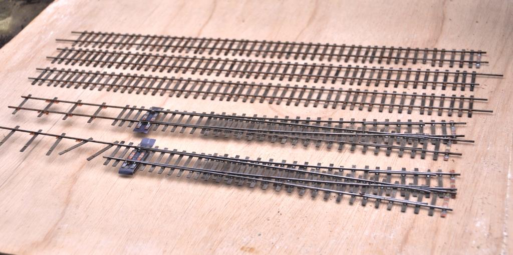
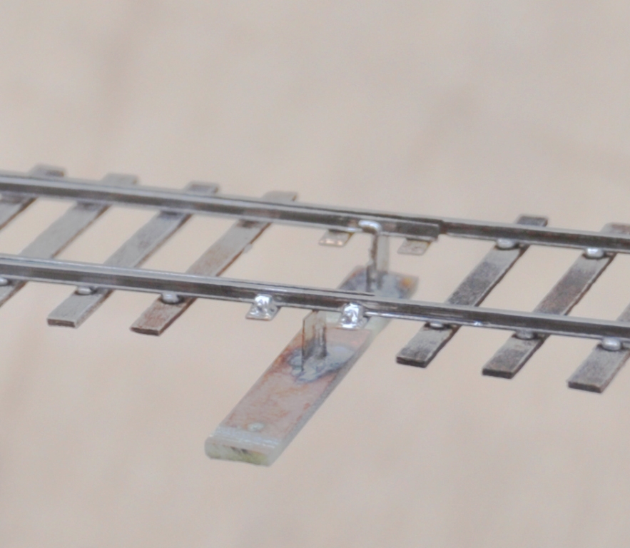
I have also developed my approach to TOU’s slightly from Portchullin. As a finished article they look like this:
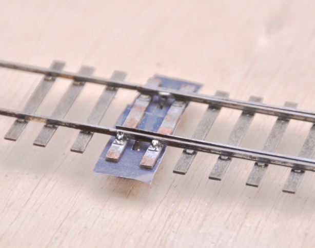
You will see that relatively little of the TOU is exposed (and when it is painted it blend away further). Equally it is much more durable than most of the other options out there because the switchblade is held by both a wire strip but also to some brass strip that is tight to the underside of both the switchrail and the switchblade. By installing this strip in this location, the switchblade is held in a vertical plane much better than other solutions. I think this leads to better running.
This is what it looks like as it is being assembled. You will see that in essence is it is merely a bit of copper clad below the switchblades, but lowered somewhat further due to the use of the brass strip. This allows the whole lot to be hidden below the boards.
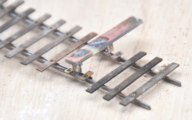
You will note the rather unusual arrangement of sleepers. This is called interlacing and was very common on many pre-grouping lines, including the Highland. I will expand on this in a future posting.
Timber!
A fairly big day in Glenmutckin’s life today; the start on baseboards.
As I mentioned in the last post; a couple of my team who help on Portchullin made the mistake of both criticising my carpentry skills and then admitting that they ran a joinery business. I guess you can see that they thus talked their way into a task and we spent day one in doing these today.
I know that a bad workman blames their tools; but by god having all the proper kit makes things much faster and a great deal more accurate!! To say nothing of someone who knows rather more about joinery than I do!!
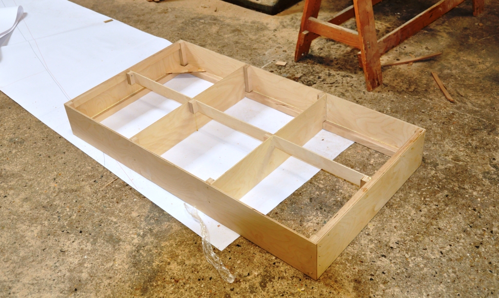
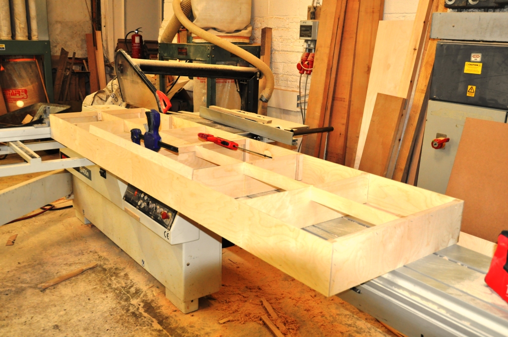
The intended design will be predominantly open design around a skin of ply. Initially a rectangular box is being made, as above. After we have made the first batch of these we will then laminate a further layer of ply around this to provide the material to support the raised scenery and also to house the rebates for the pattern makers dowels – when we have done it hopefully the pictures will make it more clear.
We got three of these boxes made today; here are two of them – what is particularly pleasing is that they are perfectly level across the joint (see the bit of timber laid across the joint). This is an area that I really did not get right on Portchullin and I note that lots of other modellers don’t either – right up to the famous person modelling Leamington Spa.
So thanks Tim and Julian – I am sure some signals can work their way back!
And a small plug for my hosts; if you are looking for a powered loft ladder; give them a try http://www.st-joinery.co.uk/electricloftladder.html?gclid=COfvoN-HyrwCFYWWtAodjCQAcw
Where did we get to…………?
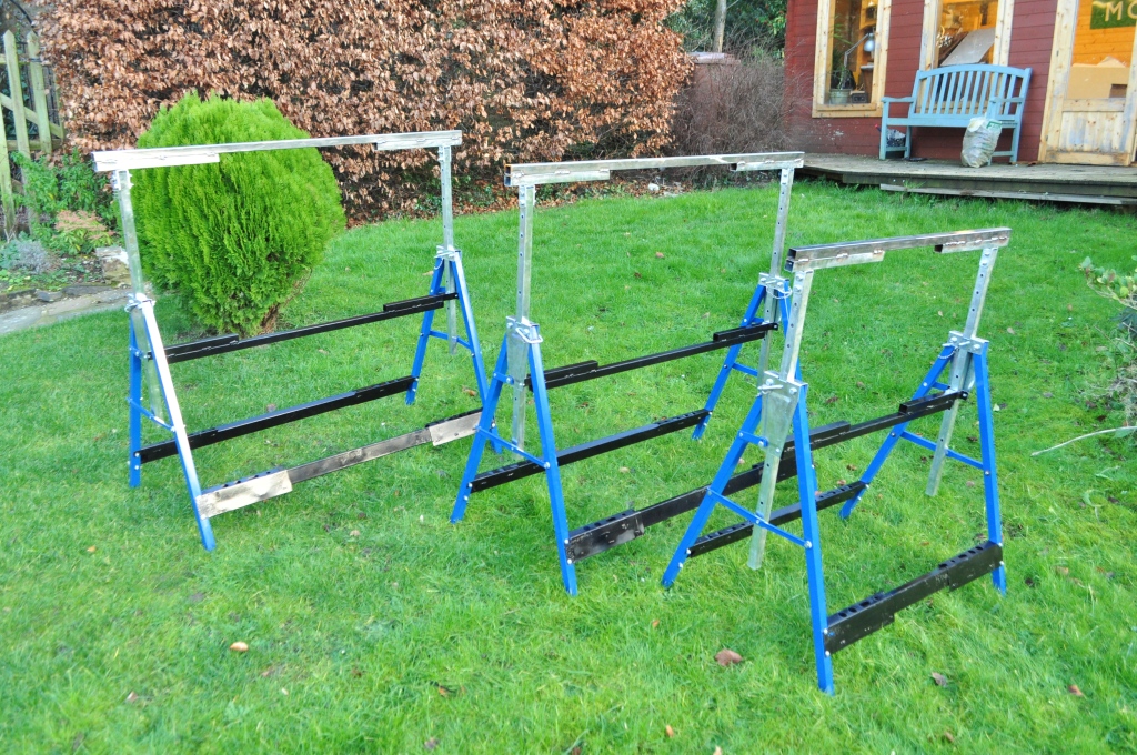
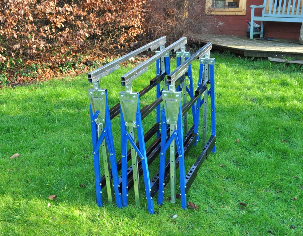
When last I updated you on Glenmutchkin, we were making the legs. These have been reassembled and look like this:
They are not yet finished as I wish to make a mount for the support girders; so it will soon be time to prevail on my brother again!! However, I have been tinkering with plans and have come up with the baseboard layout and a rather tidier rendition of the basic plan:
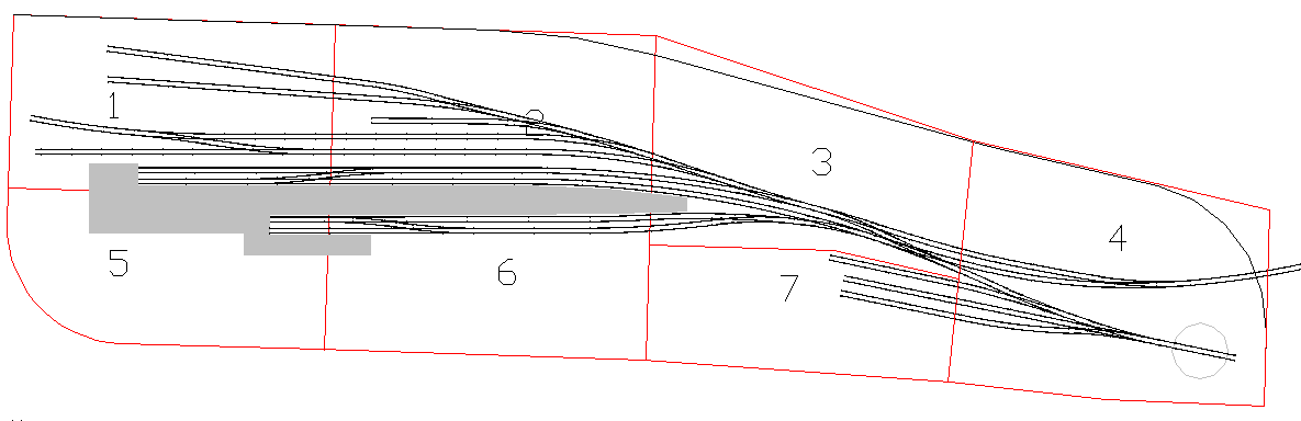
A little unusually, I am making the layout two boards deep as I am trying to get a lot of “depth of field” in the model. Portchullin works very well in this regard to the right side where there is a bank and you do not see the back of the layout but less so in the station building area or across the bridge. The depth of field is intended to try and overcome this but I will be having quite high hillsides behind again for much the same reason.
I am hoping that I have been able to book a bit of time in some friend’s joinery shop this week to make a start on the building of these. Five of the boards are relatively simple; the last two (nos 3 & 7) a lot less so. One of the chief areas that Portchullin lets itself down on is the quality of the baseboards – compensation/springing is a must on steam locos for example! My friends (Tim & Julian) pointed this out with some vigour and told me that they really knew being joiners…………well you can see where that led for the next layout!
Every favour has a price though; so I am down to build something in return for them!
Etching Artwork
I have not actually picked up a modelling knife or soldering iron for a couple of weeks now; largely because I got a bit of a bug for sorting out the etch artwork.
I have now completed, I hope, all of the artwork I will need for all of the signals that will be required on Glenmutchkin. Indeed, it should do all the signals I and just about anyone else ever needs for any scheme based on the Highland era!!!!
I am fortunate that I have a couple of an 1895 McKenzie & Holland catalogue and a further partial copy from a bit later. I have also been provided with a number of really good drawings of bracket signals from M&H, prompted by my ramblings on the web. This has given me with a pretty good handle on how they were constructed and I can draw up rather more comprehensive (and a little more specific to the Highland) artwork than are available form any of the other sources.
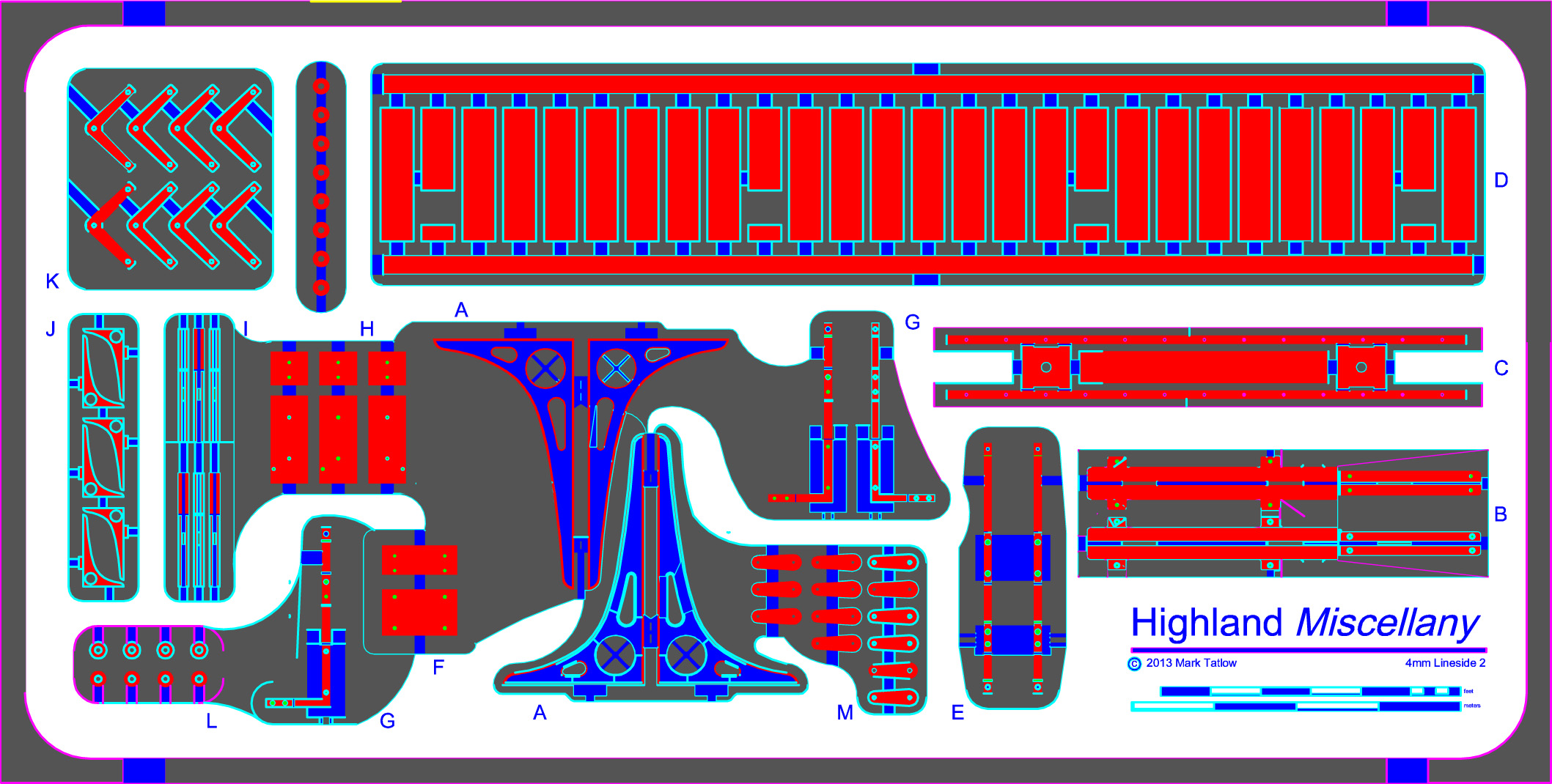
So this is what I have come up with. Firstly, an etch of all of the arms, balance weights and a track mechanism for raising the lamp to the top of the post (I think this was peculiar to the Highland):
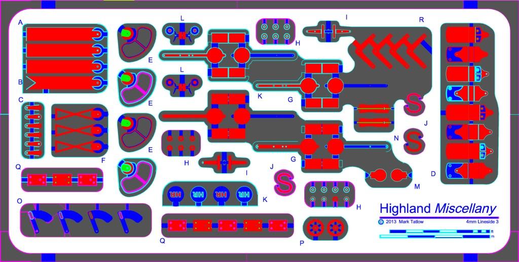
and then an etch that includes the large brackets used for the multi-doll signals and all of the support brackets and landing.
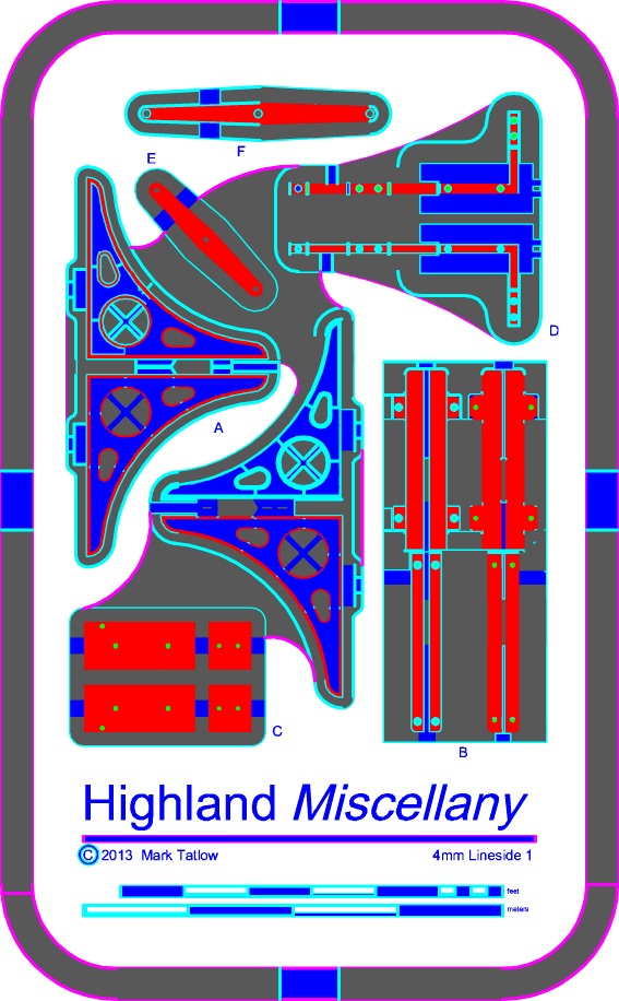
and this one is the smaller bracket; used on twin doll signals:
I have been recommended to use PPD as a first port of call for etching, so they have been winged off tonight. Lets see what a week or so brings us…………..
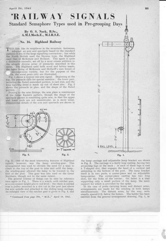
As this is now out of copyright, an article by OS Nock on the Highland’s signals from the Model Engineer might be of interest too – it may even show what I am trying to make in the etchings a little more clearly.
And for my next task, I am going to have another bash at the water column and the finial; more on this when I think I have been successful!
The Road Overbridge – Part 2
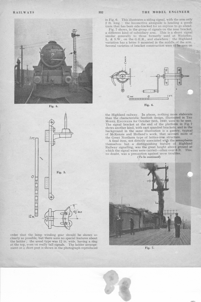
The bridge is coming along and is now close to finished (constructionally).
It has taken a lot of time with plastic filler to get the stones to meet neatly at the corners and also to be coursed sensibly at the corners. Having said this, I am inclined to think it is one of the more important parts of modeling structures and buildings. Cracks or missing sides/ends on a building are just a total no no and even an untrained eye (I am a chartered surveyor so it is worse for me!) spots the error immediately.
This is where we have got too:
Lots of filler in evidence – but there is still more too do!
The abutments end on
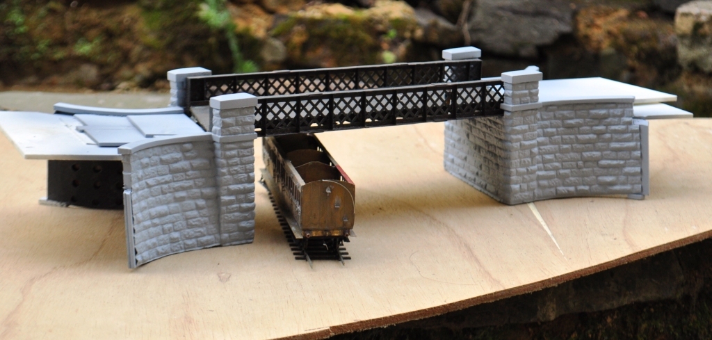
With a carriage to give a sense of scale – the Microrail Drummond All Third has only been on the stocks for 15 years………..
I am not happy with the string course at the moment, it sticks out too abruptly and possibly the same for the copings to the top of the parapet – so more filing and sanding………….
However, it does look like a bridge and I doubt the civils guys will condemn it!
The Road Overbridge – Part 1
The bridge is in fact modelled on the one at Killiecrankie, but there were very similar ones at The Mound, Kyle of Lochalsh, Keith amongst others. Heres a picture of the Kyle one:
Copyright by Ben Brookshank and reproduced under a creative commons licence
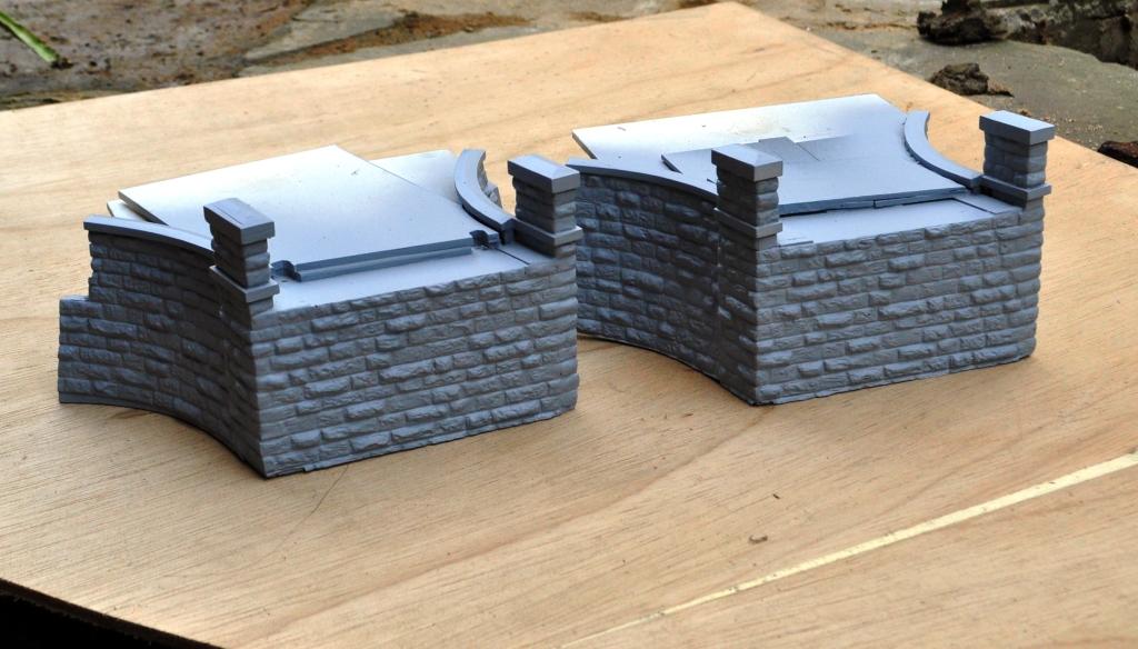
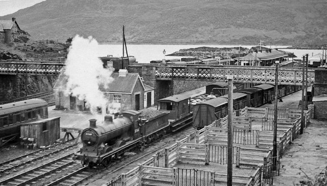
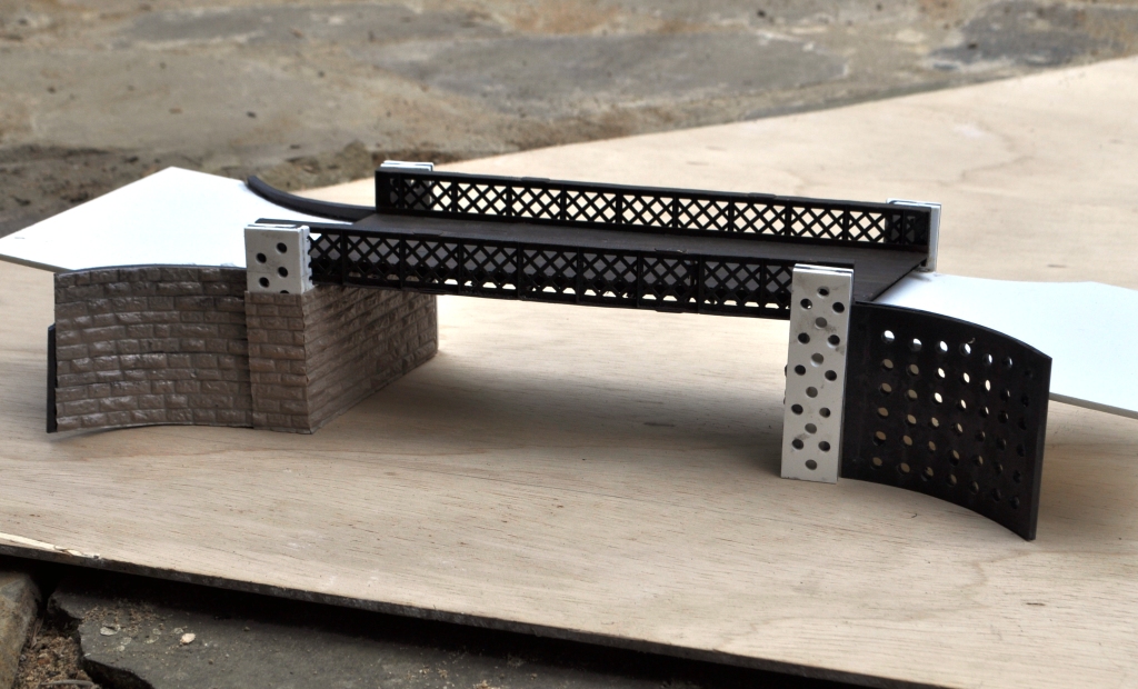
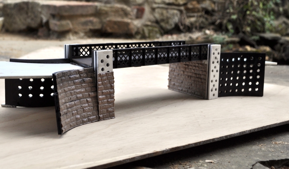
The advantage of using the Killiecrankie bridge is that I had previously modelled one for a layout of this station and whilst the abutments are still firmly attached to some mothballed boards, the deck could be reused. The deck has a nice skew to it to make it a bit more interesting and utilises lattice girders; which few seem to bother modelling. This is what it looks like:
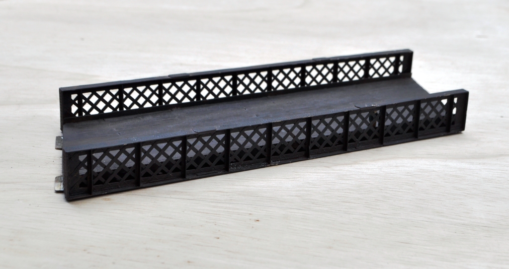
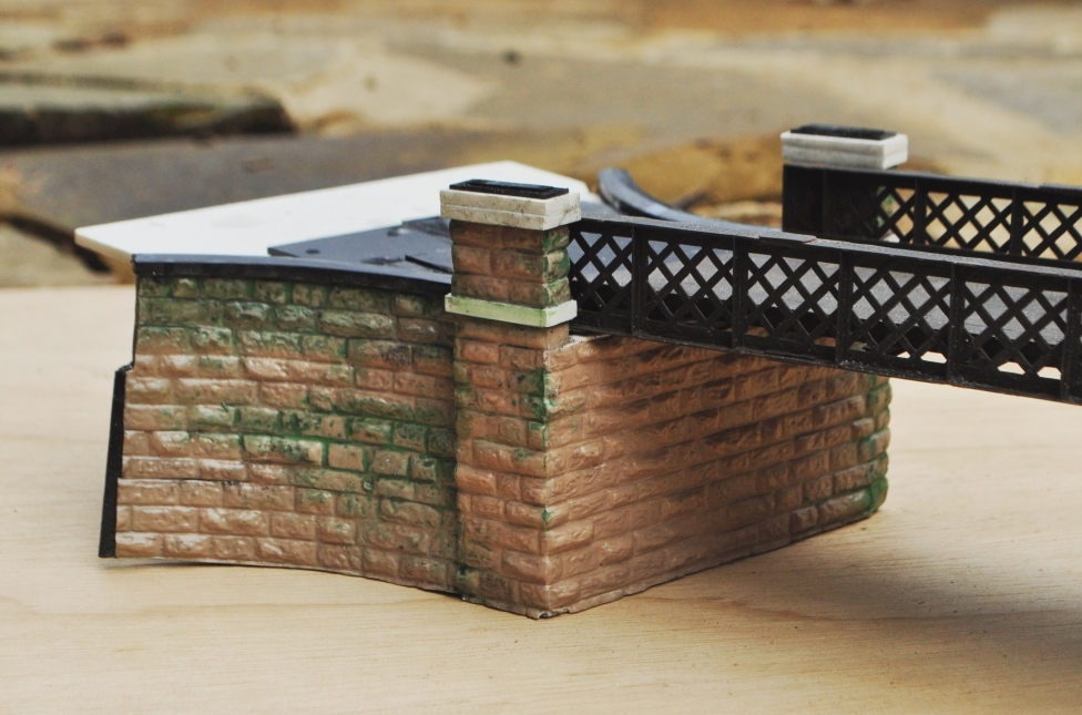
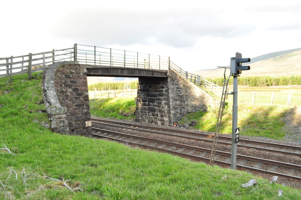
In terms of abutments, most Highland (and indeed this is common to most scottish lines) had bridges with curved wingwalls swept back from the face of the abutment. To give the layout some locational character, this was something I wished to produce. This is where we are at presently with the abutments: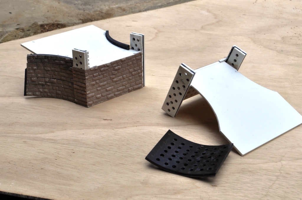 Typically, the random or dressed stone ranges from Wills are my favoured mediums but seeing Andy G making a good go utilising Slaters 7mm coursed stone I thought I would have an experiement with this. This is because many of the later bridges on the Highland used the same coarsely dressed stone; like this one at Dalwhinnie:
And these show the bridge deck on the abutments as they stand:
_________________ Mark Tatlow
