Blog Archives

Now That Didn’t Take Long…………..!
I have recently bought one of these – a minature bench saw by Proxxon – second hand from ebay for a moderate amount of money, along with a diamond disk with the intention of using it to cut copper clad fibre glass.
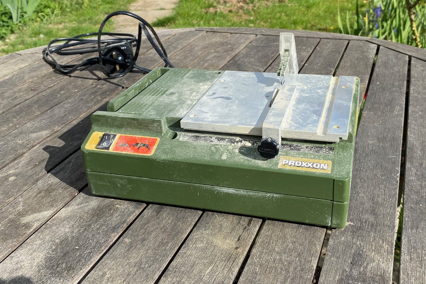
If you have attempted to cut copper clad sheet yourself you will know that it is a stunningly good way of blunting tools!
I wanted a better way of cutting copper clad sheet for frame spacers and, particularly, sleepering for trackwork. Having got it I obviously wanted to put into use…………..
So obviously I didn’t choose something simple and instead opted for a scissors crossing because I have never built one before. So here is it, a B7 turnout scissors crossing in P4 with a relatively wide line spacing as this is to be used in a fiddle yard between the up and down roads .
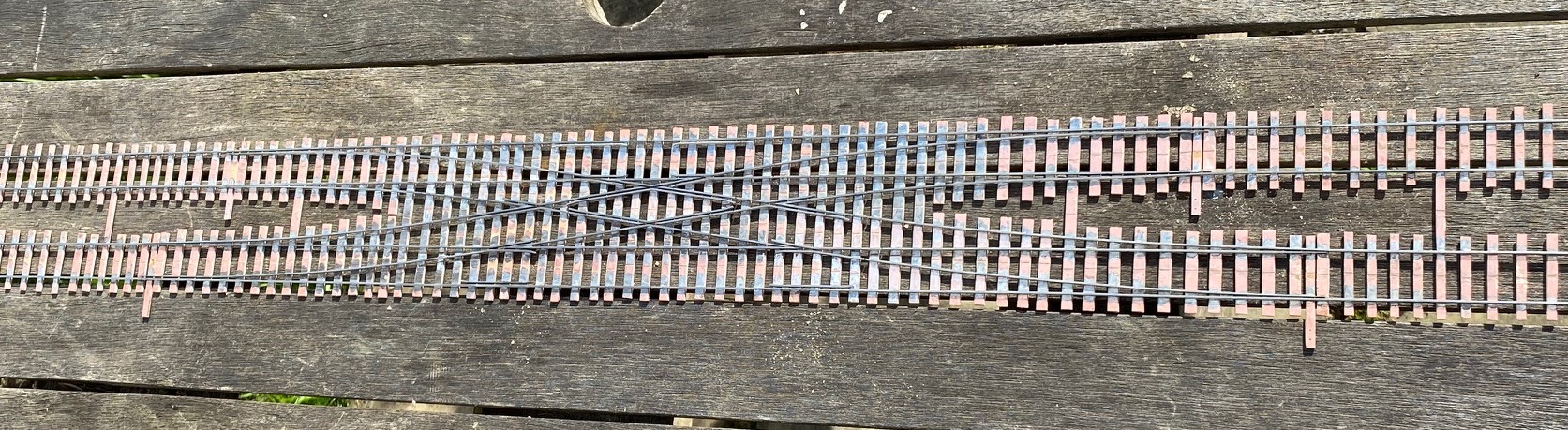
This represents over 24 hrs of work even though the time to make the sleeper bases was quite moderate.
My conclusion on the bench saw is that it is a much better way of cutting through copper clad sheet. The diamond blade slices through it easily. What is less good is that for fairly narrow strips (such as sleepers) it is difficult to get a consistant width along the strip even using a fence. Not a problem for fiddle yard track, but if it is to be used out on the front, it will need to be better.
I have also spent some time thinking through how i can wire this as it is quite challenging for the crossings for the central section. After much pondering, i have decided it is not challenging at all as i will simply cheat and use frog juicers !
Portchullin, Perth and British Railways Modelling
June is a busy month for Portchullin.
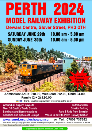
Firstly, we will soon set sail in the van to Perth with both Portchullin and Oli & Chris’ Cessy en Bois for their model railway show. The details for this are below and there are a lot of good layouts there, including the two biggest P4 exhibition layouts – Mostyn and Burntisland. So there is plenty to see even if Portchullin does not float your boat (……….as if……….). If you are visiting do please say hello.
Its a long drive to Perth from Surrey, so to break the journey up a couple of us are going to visit a number of home based model railways that you can’t see at shows. The current plan is to visit eight layouts, two preserved lines and the Perth show, so we will be well and truely model railwayed out by the end of the trip!
As you would imagine, being able to visit a number of layouts that don’t generally get seen will provoke the camera to come out andas there are a number of treats in stall, keep an eye out for future blog posts.
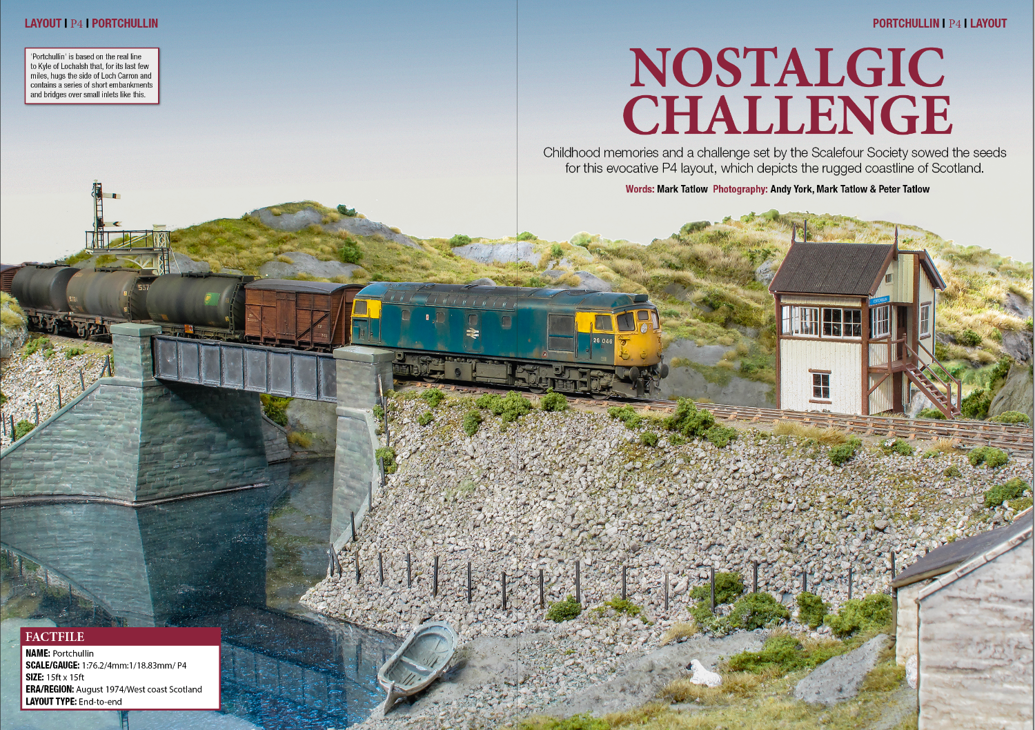
The other activity for the month has been the writing an article for publication in July 2024 issue of British Railways Modelling. This, combined with photos from myself and Andy York makes what I hope is an enjoyable article.

I have particularly talked about the origins of the layout and how it was conceived, with a smaller amount of information on how it was done. It should be available simultaneous with this post and if you have any thoughts on it, I would welcome feedback.

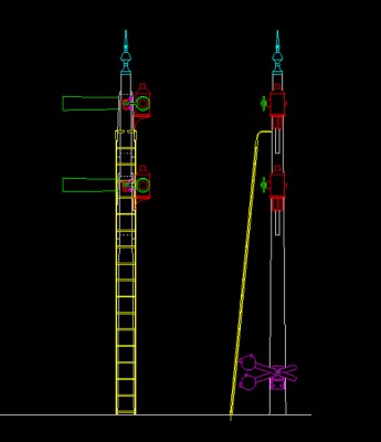
Still Swapsie – A Signal for Nampara for Hendrawna Part 2
Having assembled the basic post and ensured that it was working, the bolts can be filed away and we get to the following stage.
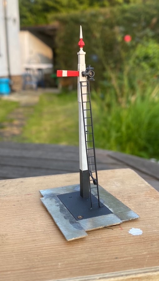
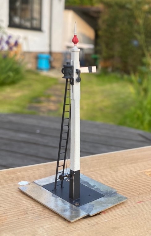
The spectacle plate plate is rather unusual in that it only has one lens which isn’t available via any manufacturer and the arm is notably shorter than I am used to so I had to etch these to suit. Although I could not find a lamp that matched what was on the prototype, I was able to modify a MacKenzie & Holland lamp from MSE to suit. Thereafter, the remaining assembly of the signal was fairly unremarkable.
And then once it had been painted, including the unusual red highlighting on the finial that I rather like:
And of course we must have the obligatory video to show that it really does work!
And for those of you that might want it, this is the drawing of the signal, which has two arms, at Didcot.
Swapsie – A Signal for Nampara for Hendrawna (Part 1)
Swapsie – the childish act of swapping things according to Wiktionary.
Do you remember at school swapping a Top Trumps set for a the latest Hot Wheels car or similar? I do! I remember getting roundly b*llocked by my mum for not recognising the value of things I was giving away and (metaphorically I am pleased to say) swapping gold bars for glass beads almost like the Incas and Cortez.
In the world of toy trains, the same happens and is very useful where someone can offer something that you don’t have (or find difficult to make) in return for something you do have. This is one such example. Sitting next to Duncan Redford at an EM Gauge Society/Scalefour Society skills day a few years back demonstrating signal construction a barter was arrived at whereby I would build Duncan a signal in return for him doing some 3D design and printing. I think it is fair to say that neither of us have rushed with our respective shares of the bargain but with the next ExpoEM only a week away, I have shifted into gear to finish the started signal that was my part of the deal.
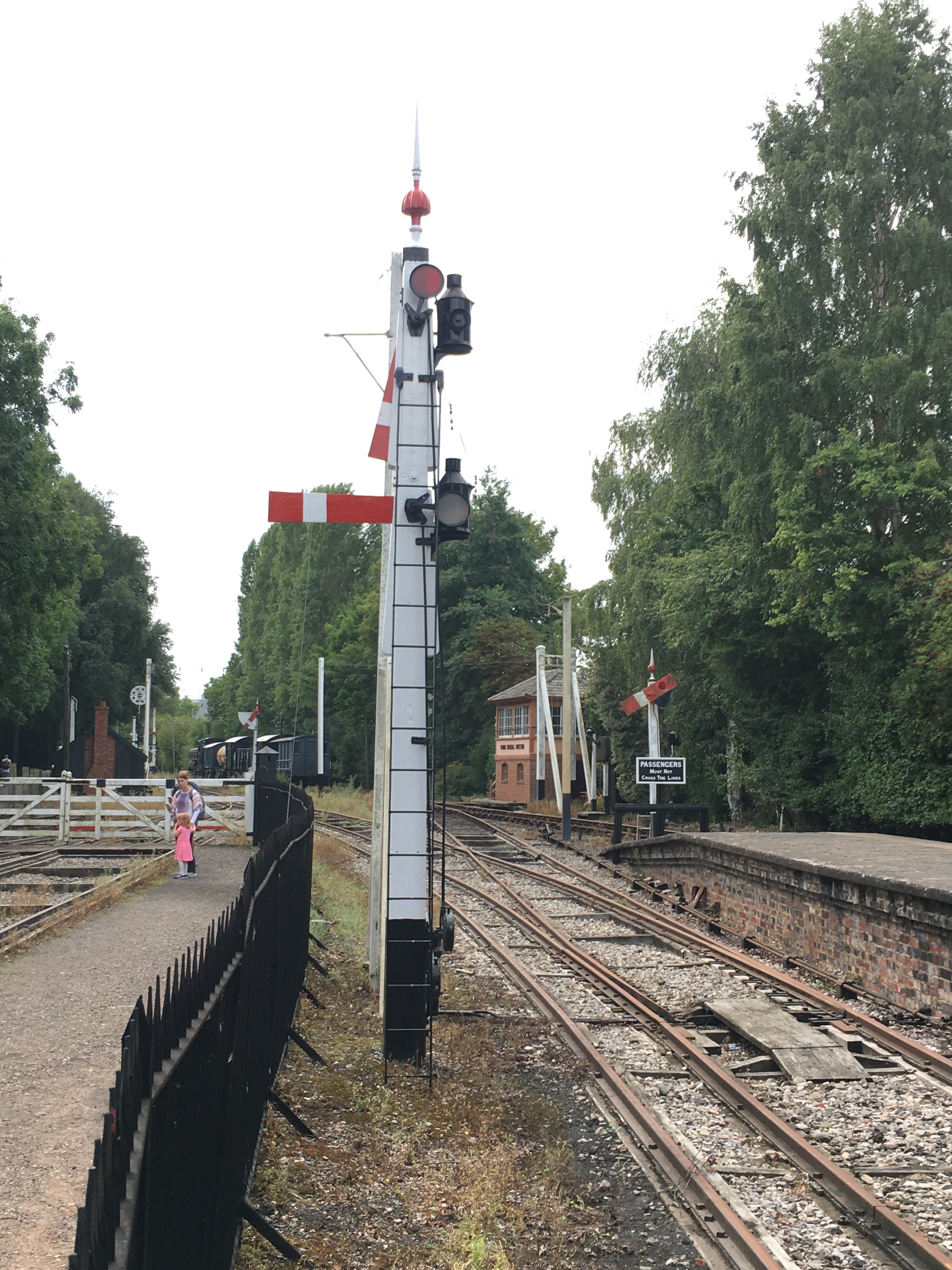
Duncan is building a GWR broad gauge era layout and wanted a close replica of a signal that the GWR Society has recreated at Didcot, but adjusted to have only a single arm. So after coming out in cold sweats about the idea of modelling anything GWR (!!!) I took a look at it. Like many signals, there are differences and similarities with other signals but after a bit of study it became clear that it was sufficiently different that a site visit to Didcot to be required.
Having measured it up including, when no one was looking, a climb to the arm/lamp to measure it, I came home to draw it. I was shocked to find that it was tiny; 3mm/1foot at best and I had a panic attack -had I mucked it up and mis-measured it. Obviously, being a professional surveyor I could not possibly have done that, could I? After a few months, the fear that I had niggled on me and so came about site visit number 2 and a further climb up the signal ladder. Nope, it really is tiny – both the post and the arm are notably smaller than I am used to.

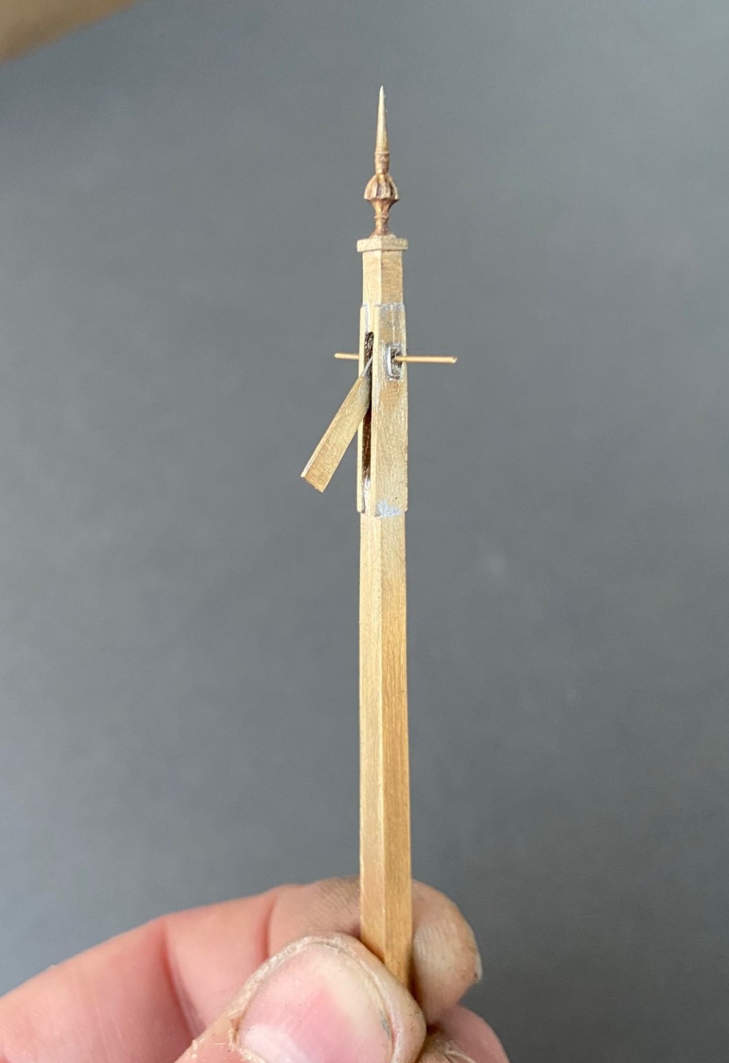
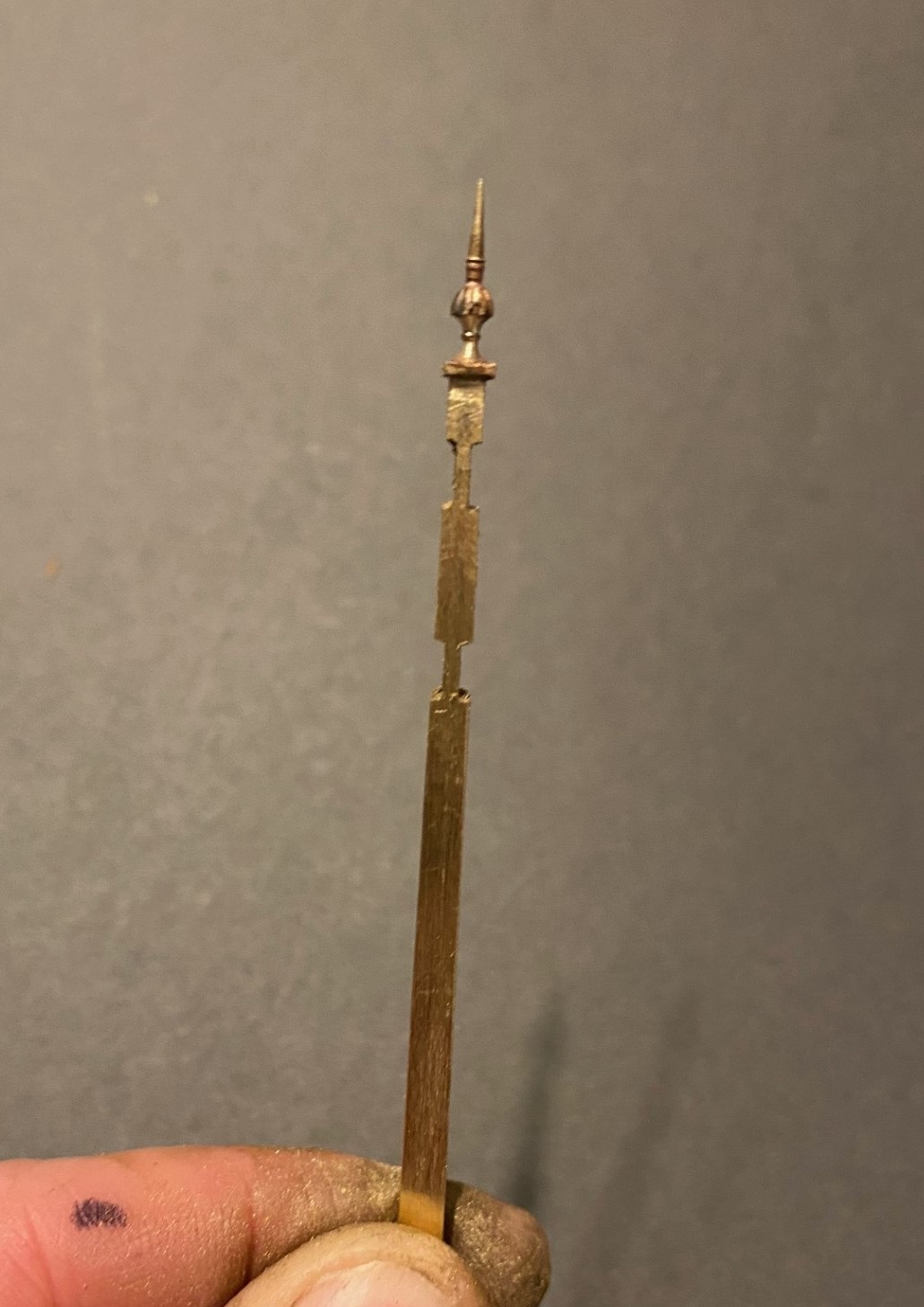
There are several unusual aspects to the signal; the one glass spectacle plate, the tapered arm and the very pronounced stiffening around the slot in the post were all going to be key to capturing the character of the signal. So out came the computer and a small fret was added to an etching order for the arms/spectacle plates. I then formed the basic post from 4mm square section brass which I filed to a taper with a 2.5mm cross section at the top.
Despite having built a few slotted signals already, they are still pretty difficult to get to work well. The difficulty that I have had is to get a soldered joint onto the arm spindle when it is encased in the brass post around it that acts as a heat sink. On a number of occassions the joint has broken and the arm no longer operate. I was determined this was not going to happen this time and have adotped a different approach, by assembling the arm first and then mounting it within the post whilst this was being assembled.
I had filed some 4mm square section into a taper to form the full length of the post. Even though I was about to cut a section of this out, it is necessary to form the full length of the taper so that it is consistent across its full length. Once I was happy with this, i filed two pairs of slots in the outside of the post on oppposing faces. The depth of these was such that the tongue between them was the correct size for the slot in the post. I chose to mount the finial at this stage, with some 296o solder and a lot of heat (from a minature blow torch). This is what it then looked like:
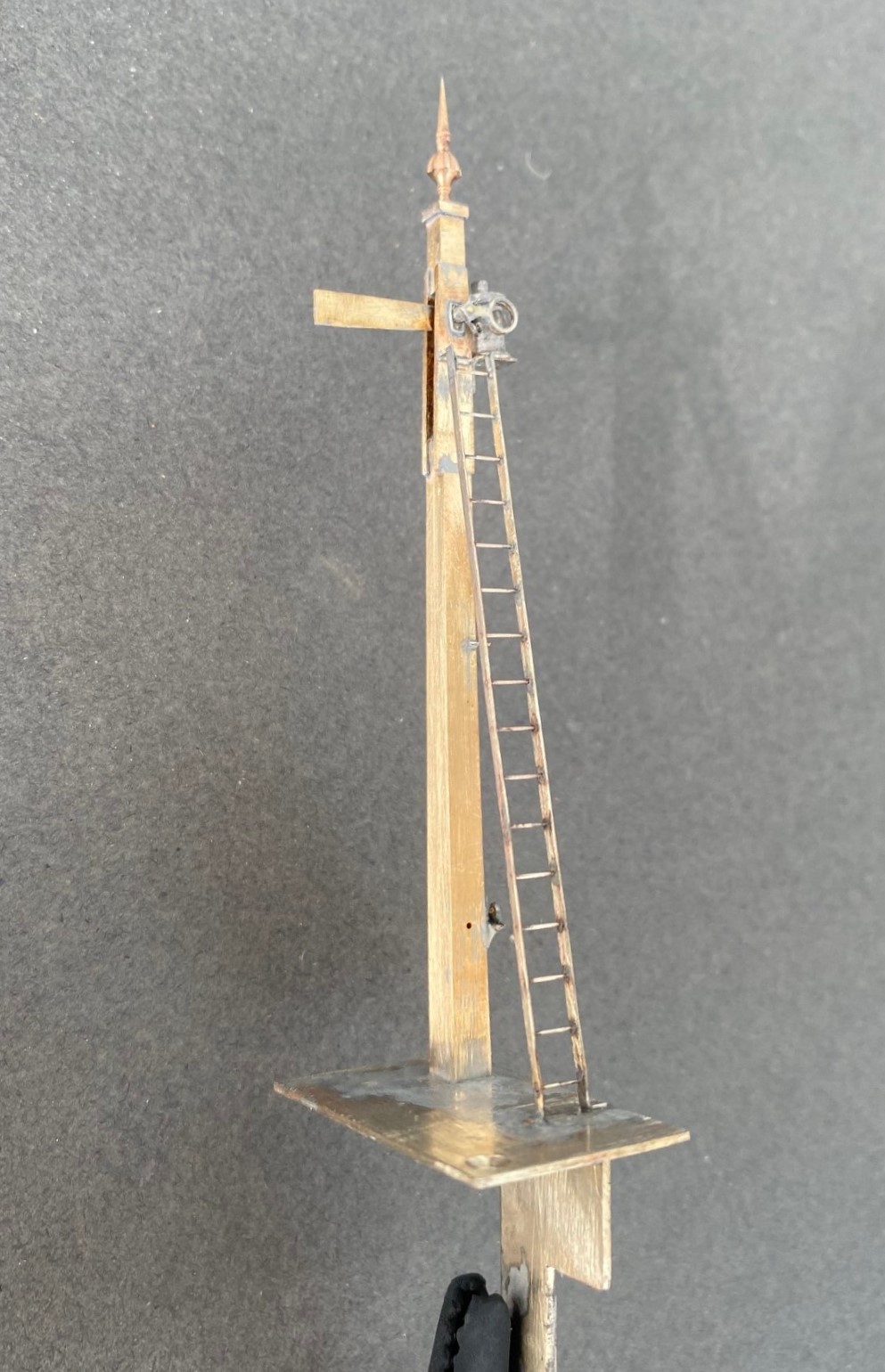
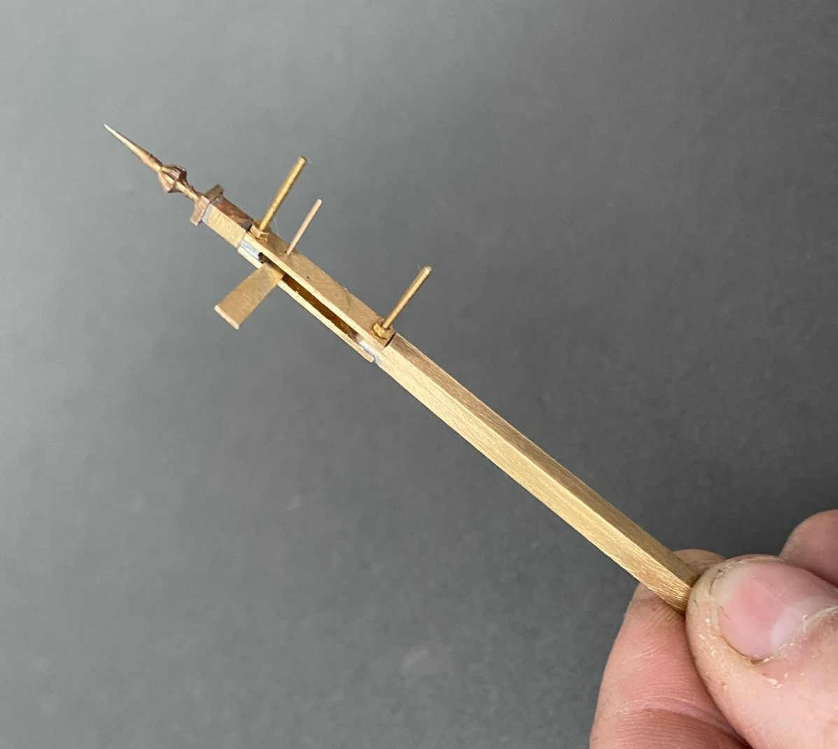
Next, I cut away the block of post that sits between the two filed sections to create a hole in my post. As there is around 2 hours of work to get the post to this point, it is a bit nerve racking chopping it like this! I then cut a pair of 1*4mm brass plate lengths to sit on the tongues and drilled both to receive a 14BA bolt. This was threaded through the first of the plates and adjusted until this a continuation of the taper of the post – this entails some filing of the metal to make the outside face match the post and plate match. It was then soldered in place, again using the 296o solder and a blow torch, to look like this:

The photograph above shows that these plates were wider than the post, in practice the prototype acheived this by planting timbers across these sections but it is easier to do this by way of using the sider plate material.
Temporarily mounting the second plate enables the hole for the arm spindle to be formed through both parts of the arm. The arm was now attached to the spindle with more use of the 296o solder and the use of a couple of minature washers either side of the arm so that I could be confident that the joint would hold.
Releasing the second plate now allows the arm/spindle assembly to be inserted and any adjustments made to ensure that it can move freely in the slot by securing the second plate in place with a 14 BA nut. The nuts and bolts are scarificed in the build by leaving them in place for the next step because once I was happy that it was correct I soldered the second plate in place including the nuts and bolts. This time I used 145o solder which meant that it would not disturb the first plate as I was doing this and this is what it then looks like – a slotted post with an arm within that is firmly attached to its spindle!
More to follow; including the second piece of bartering that I know someone is looking out for progress on!

Delayed Delivery – Part 2
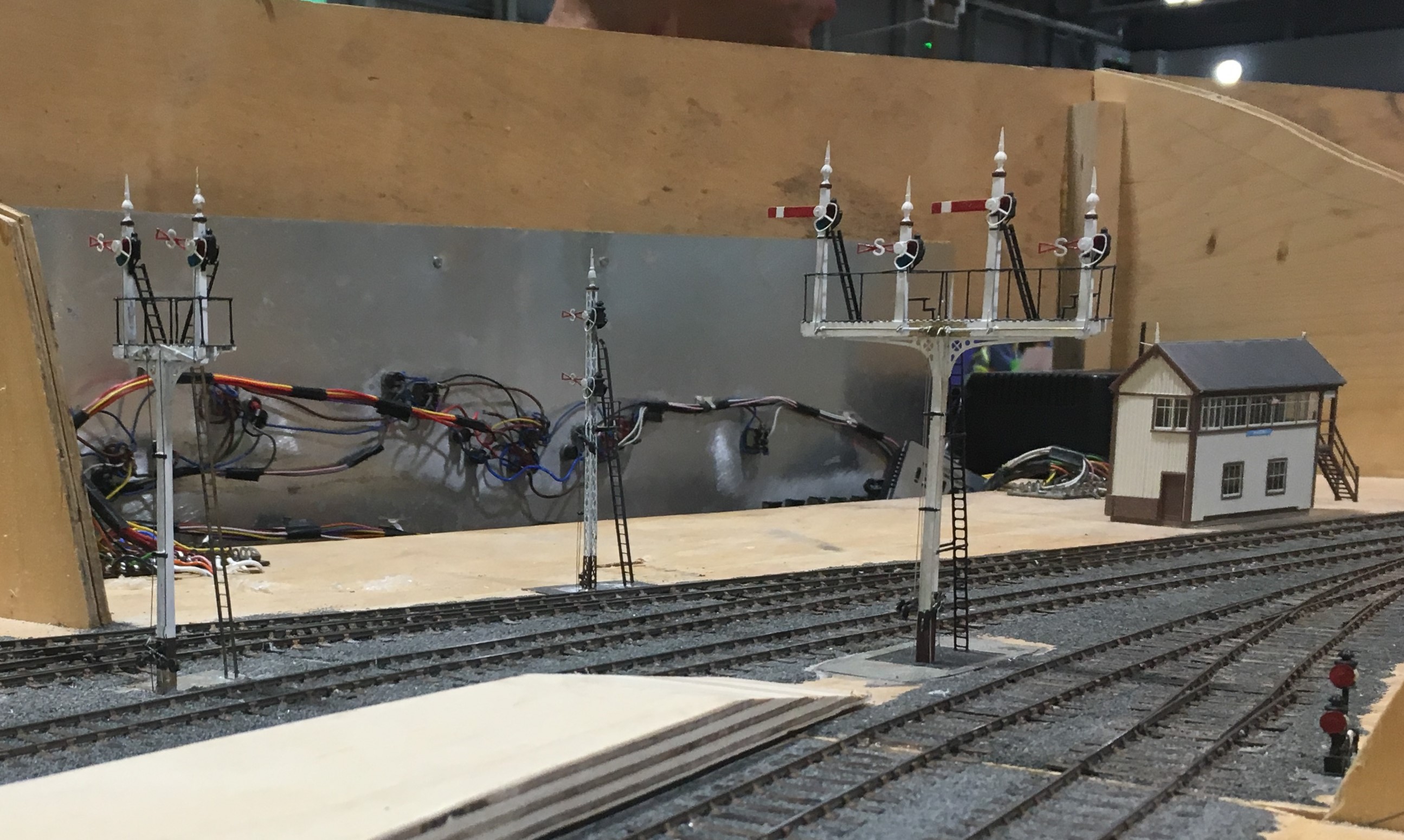
Once the basic structure of the gantry is in place, the real task of making the signals signally commences. First up were the smoke deflectors and the brackets for the balance weights. Also fitted are the main portions of the fan route indicator, but that will be explained further once I get it going!
For the arm bearing point and lamps I am using some 3D prints produced by Steve Hewitt and available from Shapeways. They can be found here https://www.shapeways.com/product/JJRSB … arketplace. They are fairly expensive but they are neat and save a lot of manufacture. There is, however, a but – they are very delicate and I am very fearful of thier long term durability. I am highly likely to draw some of my own up and get them cast in lost wax. It will make them even more expensive but I have about a 50% casualty rate at the moment, so maybe in the long term it will be cheaper!
The arms are Masokits, these are definitely the best available arms for LMS/LNER/BR semaphores. This is especially true of the minature shunt arms as the MSE ones are simply too delicate to bother with (imagine how do I know that………….!). So this is where we are now at with the arms mounted temporarly on the bearings.
There are five movements in the down direction (three of which operate via the route indicator) and then a pair in the up direction – hence the back to front arms.
The plates at the top of the dolls are mounting points for ladders. It transpires they are wrong and have already gone!
So the intensity level has dialled up a notch with these portions (especially breaking the bearing/lamp fittings) but it really gets interesting when you try and make these things work.
I don’t know myself yet (although I know for the couple of arms I have finished, so I have an inkling), but i think it might be fun to have a little sweepstake on how many moving parts there will be in the finished gantry. Five arms, three fan route indicators and each is operated by way of angle cranks. Each arm, crank and intermediate wire counts as a moving part, as do the servos………………..guesses please?

Delayed Delivery – part 1
After a long pause, caused by that irratating thing called life getting in the way, I am looking to deliver on some long made modelling promises over the holiday season.
The major task is a rather full on gantry signal with no less than eight movements on it (which is an improvement, when initially designed it had nine!), including a rather natty fan route indicator. This is for a friend’s layout and is in return for some signal cabins that he built no less than 15 years ago – I told you the promises were long made! Mind you, he hasn’t got the layout fully running yet, so I am still ahead of him!
The gantry spans only two lines so it can be formed with channel section. There are good drawings and pictures in LMS Journal no 5 of this. I have made mine from milled brass section and then the landing was a custom etch I designed as it takes a surprisingly large amount of material and effort to construct this from scratch. These etches included the doll base plates although the dolls have a thickened tube at the lower level which of course I forgot and had to undo later work to put on!!
The signal is to be located on an embankment which meant that I could not simply put flat base plates on the foot of the gantry columns. Instead I have constructed a housing that matches the slope of the embankment and then the baseplates are partially sloped to match this with square sections representing the foundations of the prototype columns. Below these baseplates I have then formed housings to take the servos which will eventually operate the arm actions.
So far, this is pretty easy modelling (although I lost a number of drill bits opening up the stanchion positions on the landing – grrrrrr!). The tough bit comes next……………
There are potentially two viewers of this thread who might be thinking that I have long outstanding modelling promises to them too……………I am also working on one of these too!!

That was the weekend that was….
Well the layout made it to and from Scaleforum – possibly I did too!
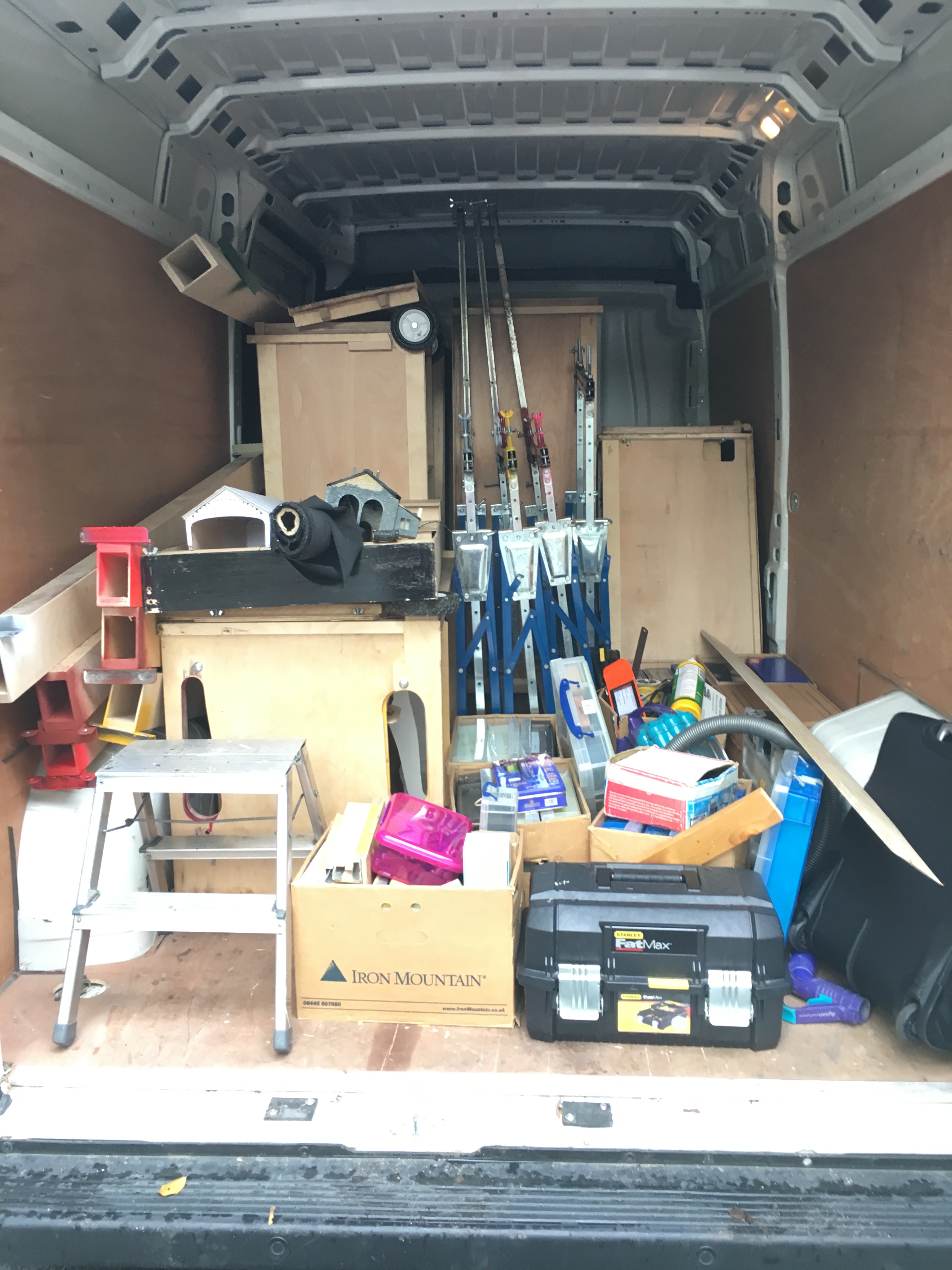
Last Friday, the inside of the hire van looked like this. Whilst the cases worked a treat, the dismantling of the layout from being set up on my own took a long time – much longer than I had hoped or expected.
Once at the venue, I was able to press gang some “volunteers” to erect the layout and this was much easier.
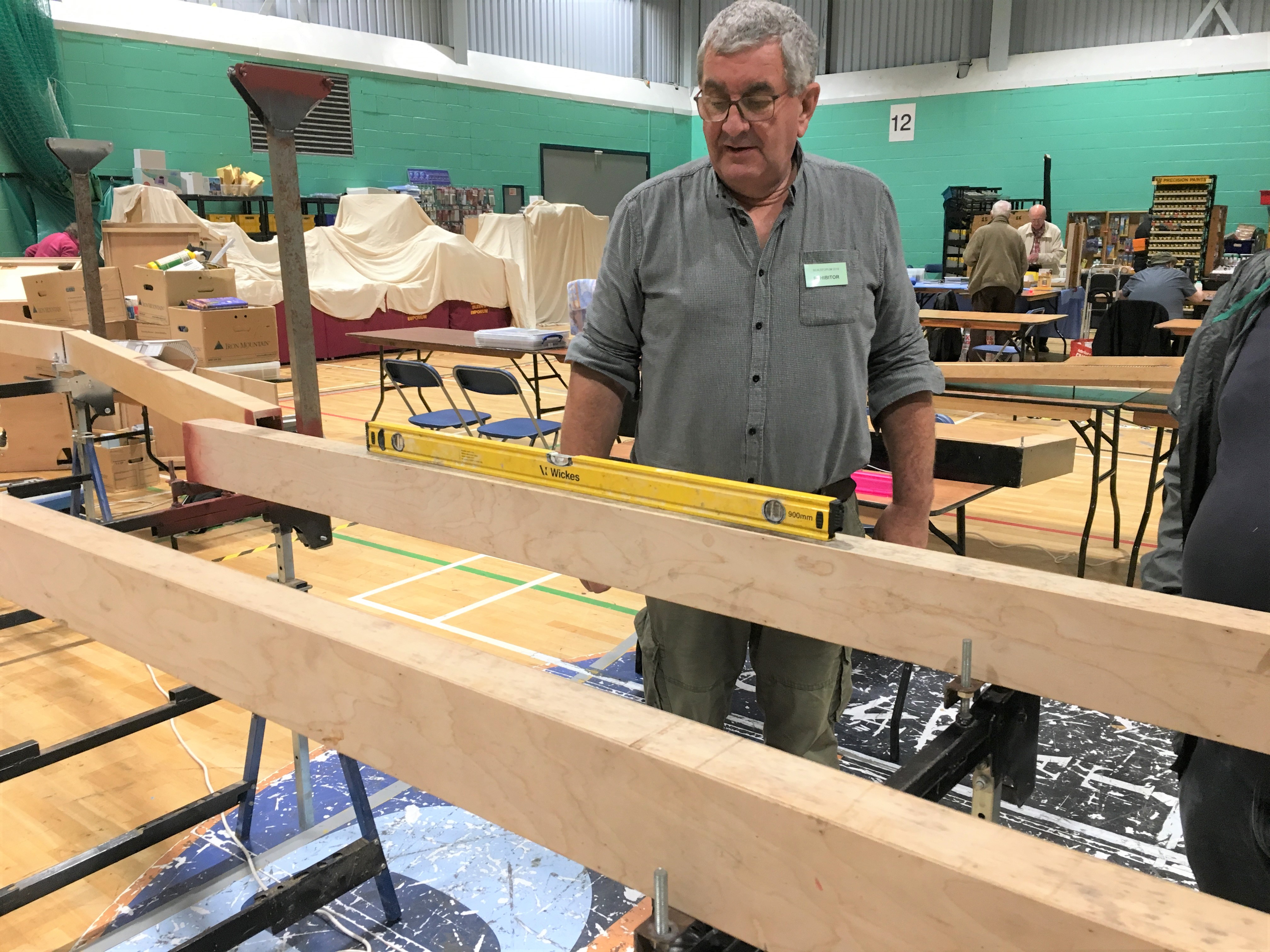
Getting the beams levelled up was speedy even though none of my press team had any experience of my logic! Indeed, with their help, it assembled itself quicker than Portchullin does although the jury is out in my mind as to whether this is simply because it as yet has rather less on it!
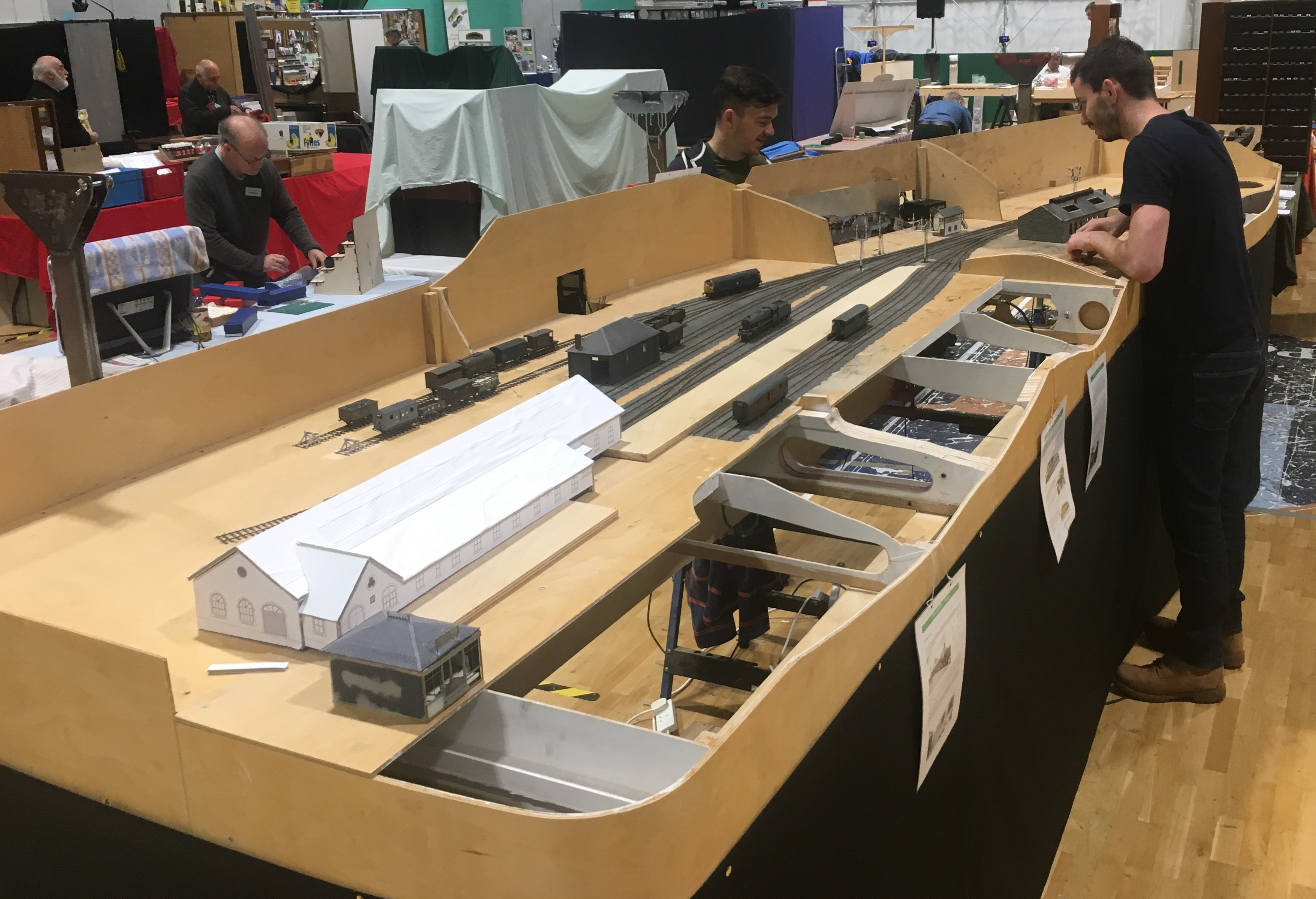
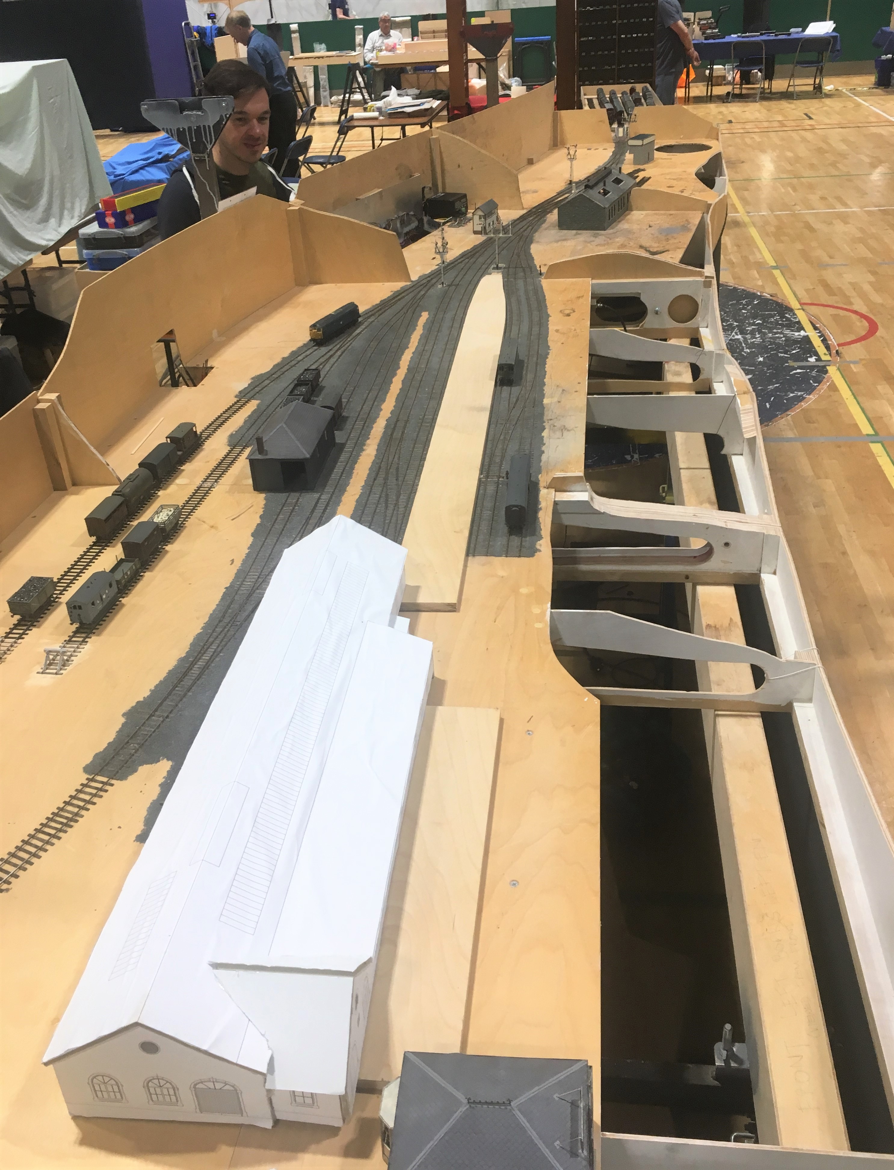
The layout’s size quite quickly became apparent; especially its depth – as can be seen here with Chris in the background for a sense of sale! Please don’t tell my wife this is actually quite big, I have been telling her it is pretty normally sized!
I did not manage to get front side all that often so I have only fairly limited numbers of photographs. Fortunately Samuel Bennett has come to my rescue and has provided a number of photographs to show what it looked like to the visitor.
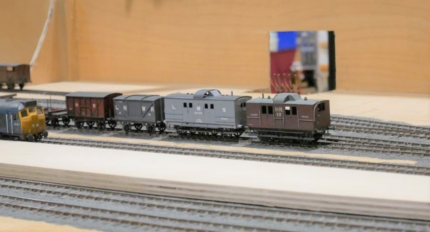
We only had three correct Highland locos chipped up (and one of these decided to sulk after a couple of hours!) so we did break out the blue diesels to make sure we had a fully operational layout. Above there are a few of the locos awaiting chipping on shed and below we have the scene 50 years later!
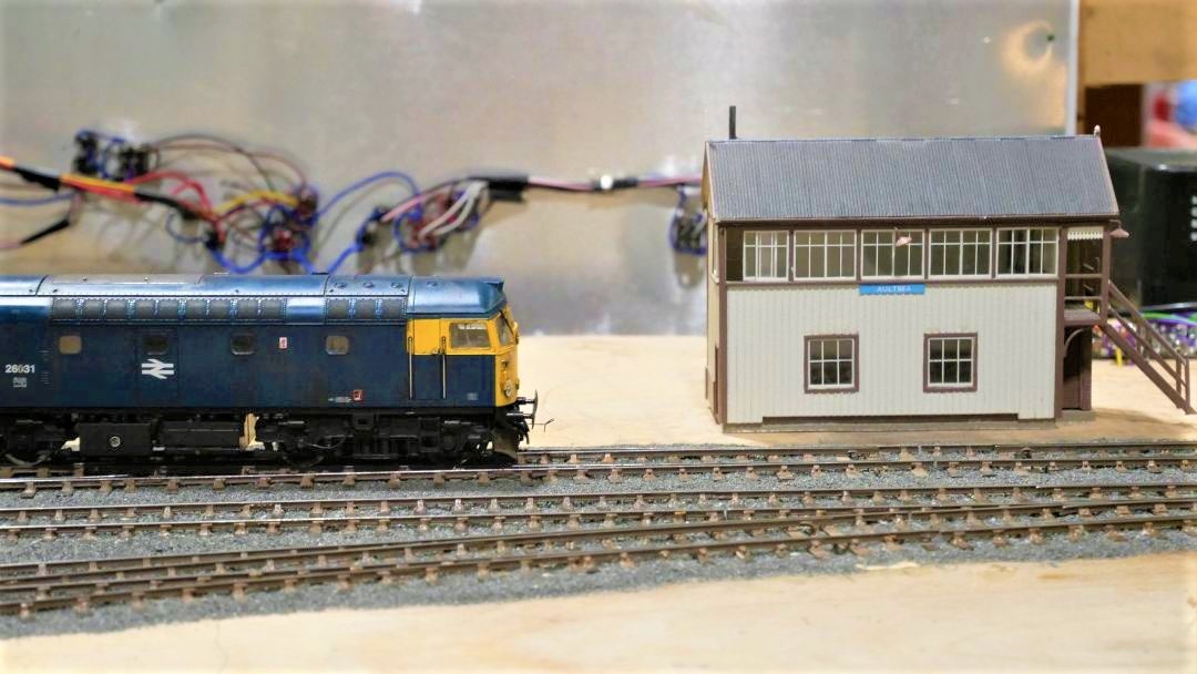
……..and below is simply confused!
Although the layout did not operate perfectly, it did behave much better than I (and my operating team) had feared! The two page list of faults and issues to resolve with the trackwork, wiring or stock is a fraction of the list that would have existed after Portchullin’s first outing (if I ever had one!).
The signals received a lot of comment, even if there was one missing because I managed to damage it as I was packing the layout. There’ll be another post on these soon.

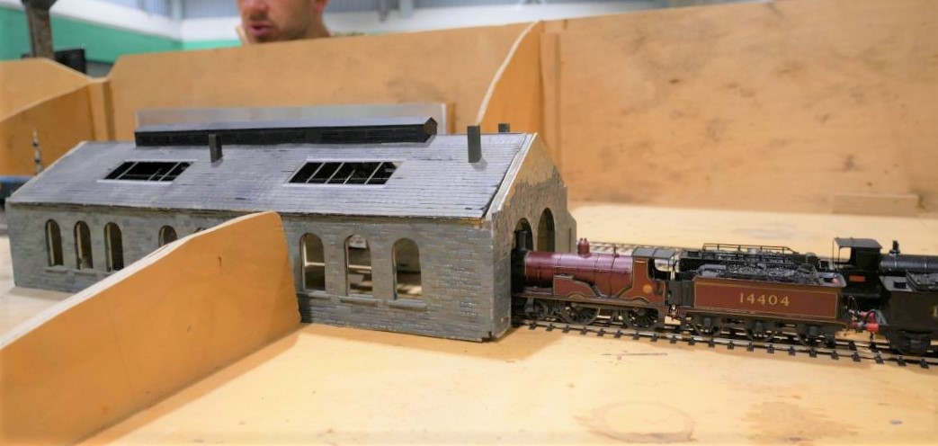
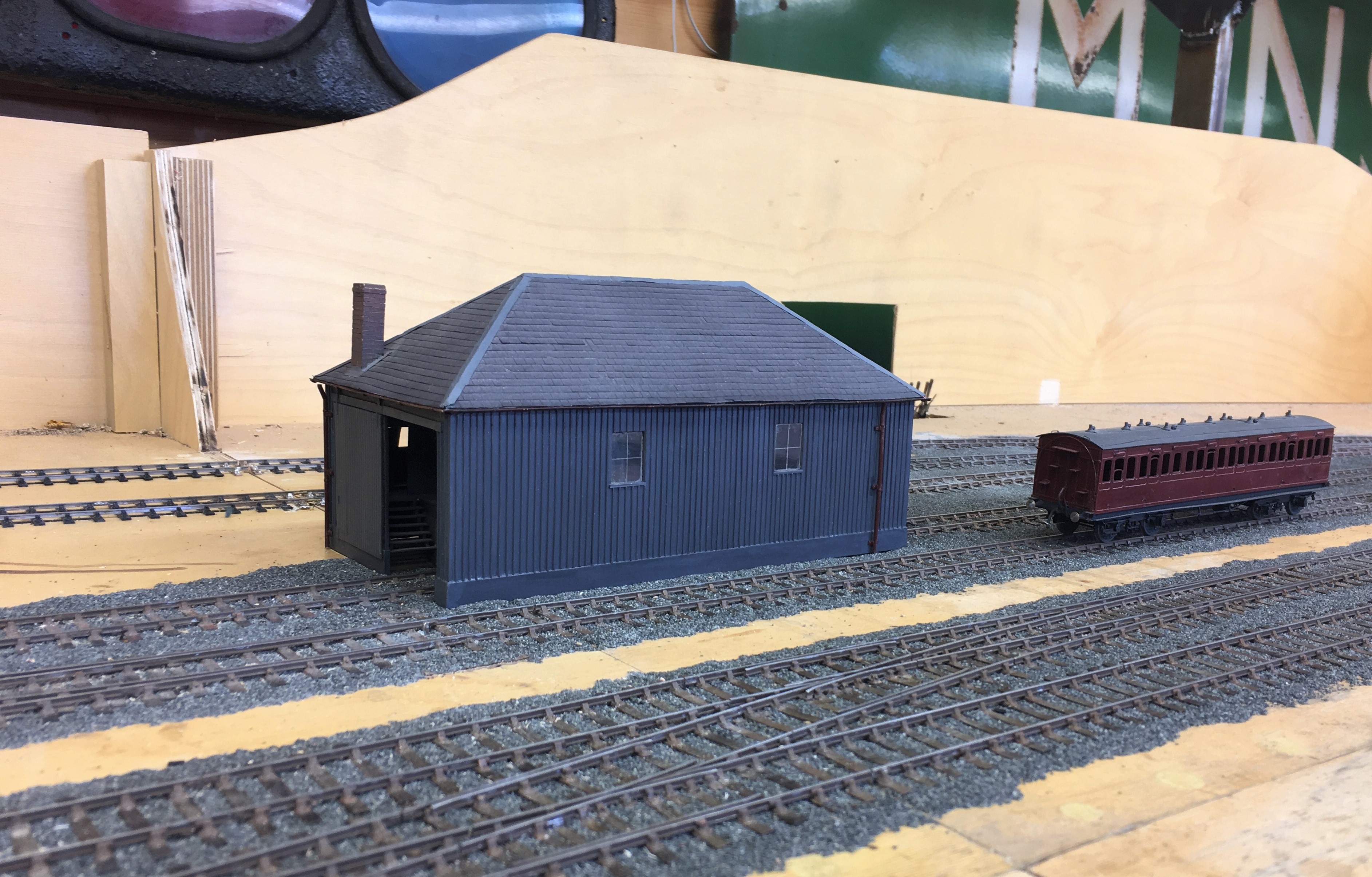
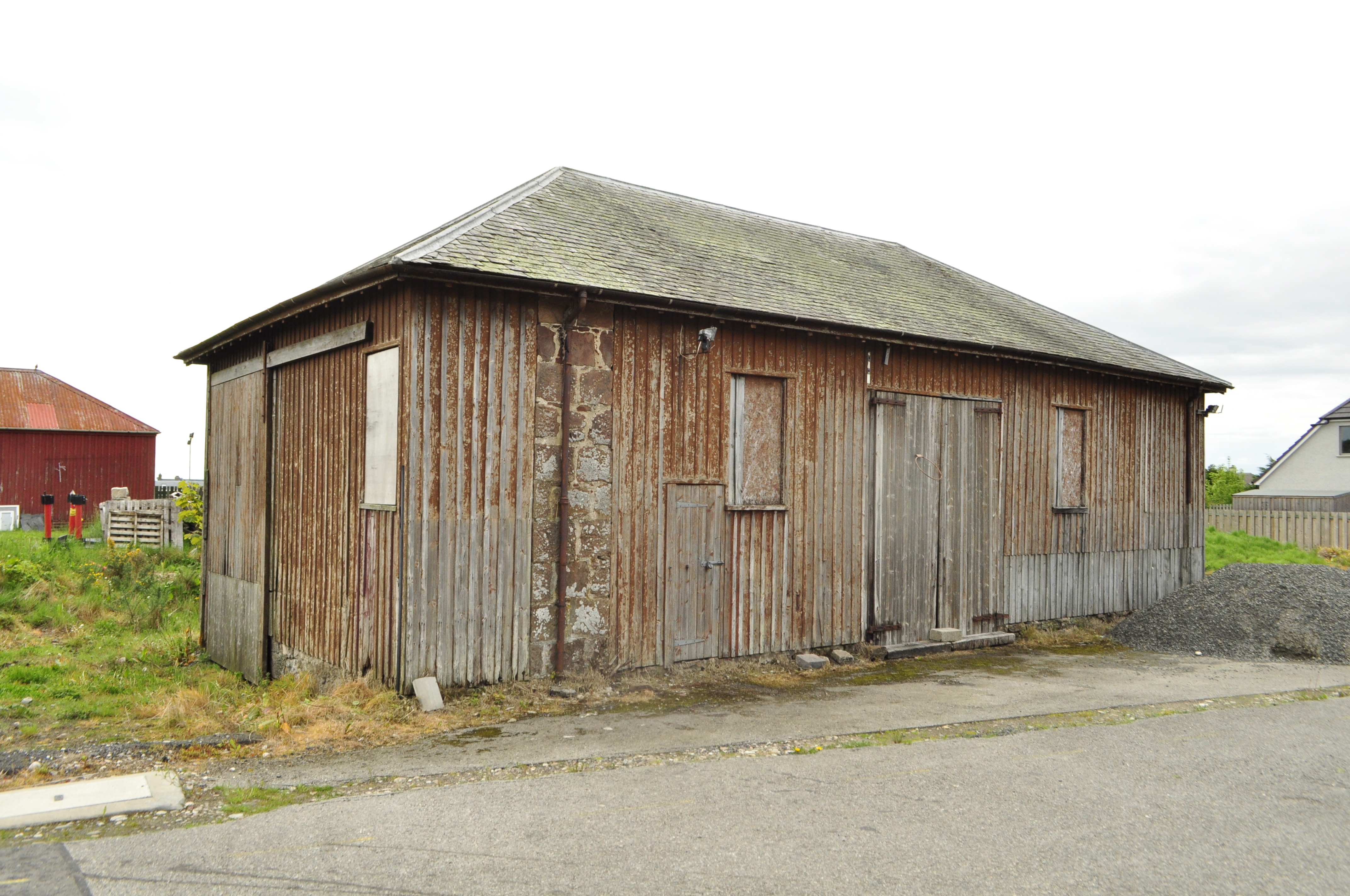
Putting a Backbone into a Shed
The advantage of a railway company using standard building designs is that you can get to use them more than once. Thus Portchullin’s goods shed will be getting to have a new lease of life on Glenmutchkin.
I think my goods shed is the oldest model that I still have and over the years it is fair to say has suffered. Some of this is simply the thirty six shows that it has done with Portchullin (hell………thirty six shows…….!) and almost as many years, as I was about 17 when I made it. However the main issue was the manner in which I built it, with minimal bracing over the top of the entrances. This has lead to it breaking its back and despite several attempts at repair, these have never been long lasting. So it is time to do it properly to allow its reincarnation on Glenmutchkin.
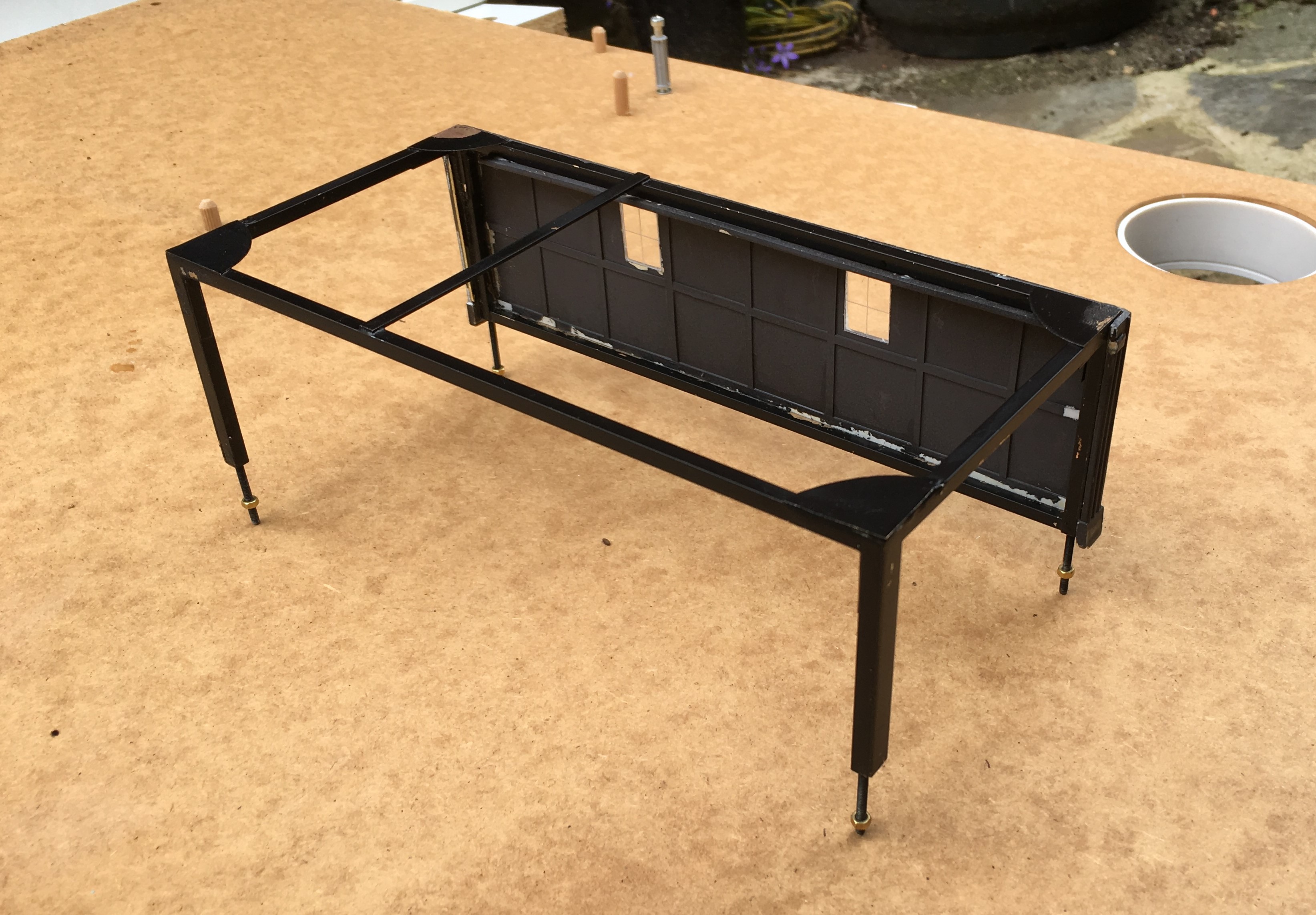
The key to the repair was to introduce a metal skeleton frame inside the model to strengthen it – particularly across the rail doors. This is something I now tend to do at the outset with any largish building I build to contain warping. The frame is invisible from the exterior – the view above shows the frame that I made with the first side attached.
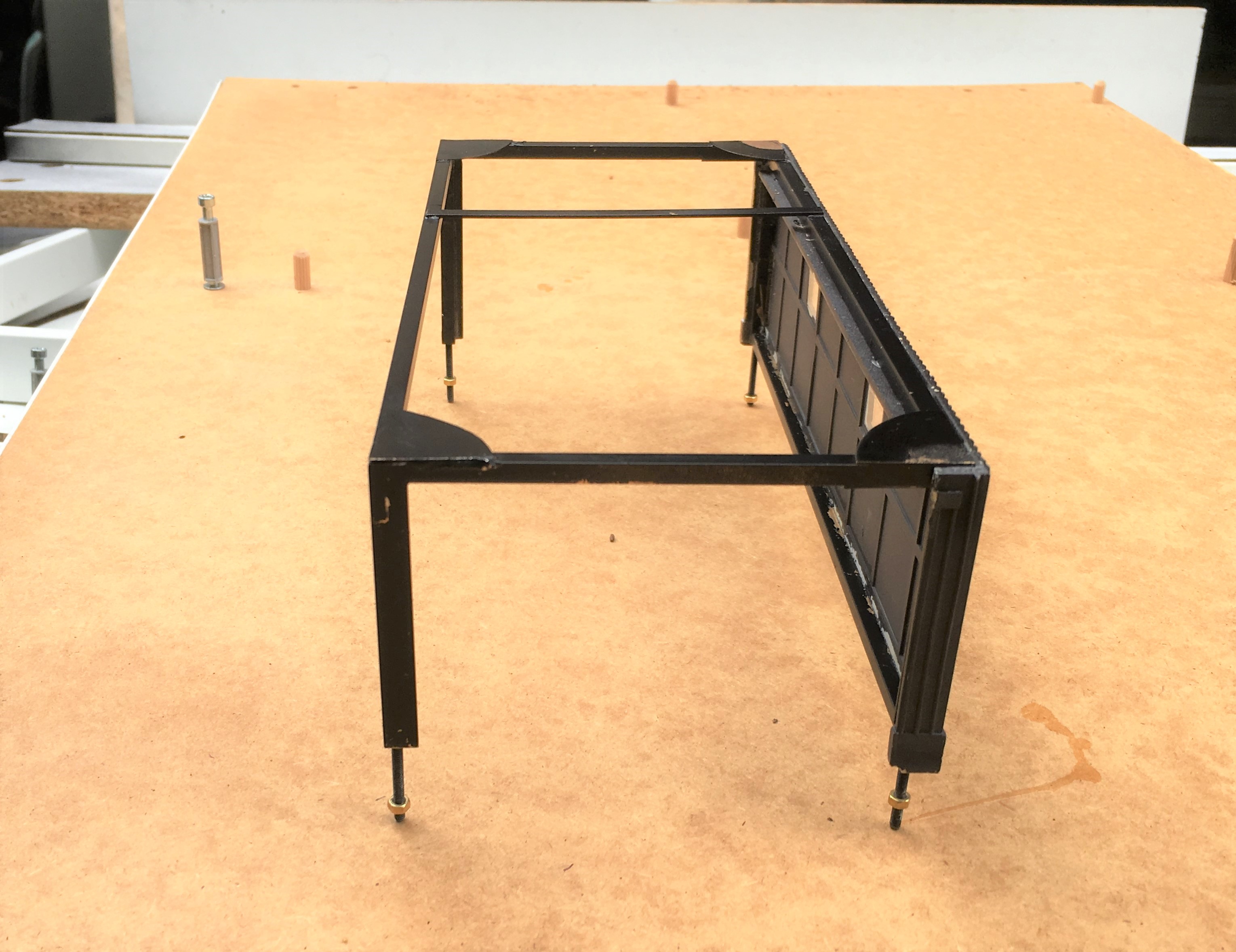
The frame was made with some 3mm square and oblong section brass, with gusset plates – there was a fair amount of metal so it got close to blacksmithing at one stage.
Once the frame was inserted, the model was given an overhaul to repair the other dinks and marks that it has acquired over the years. There were a fair few, as can be seen.
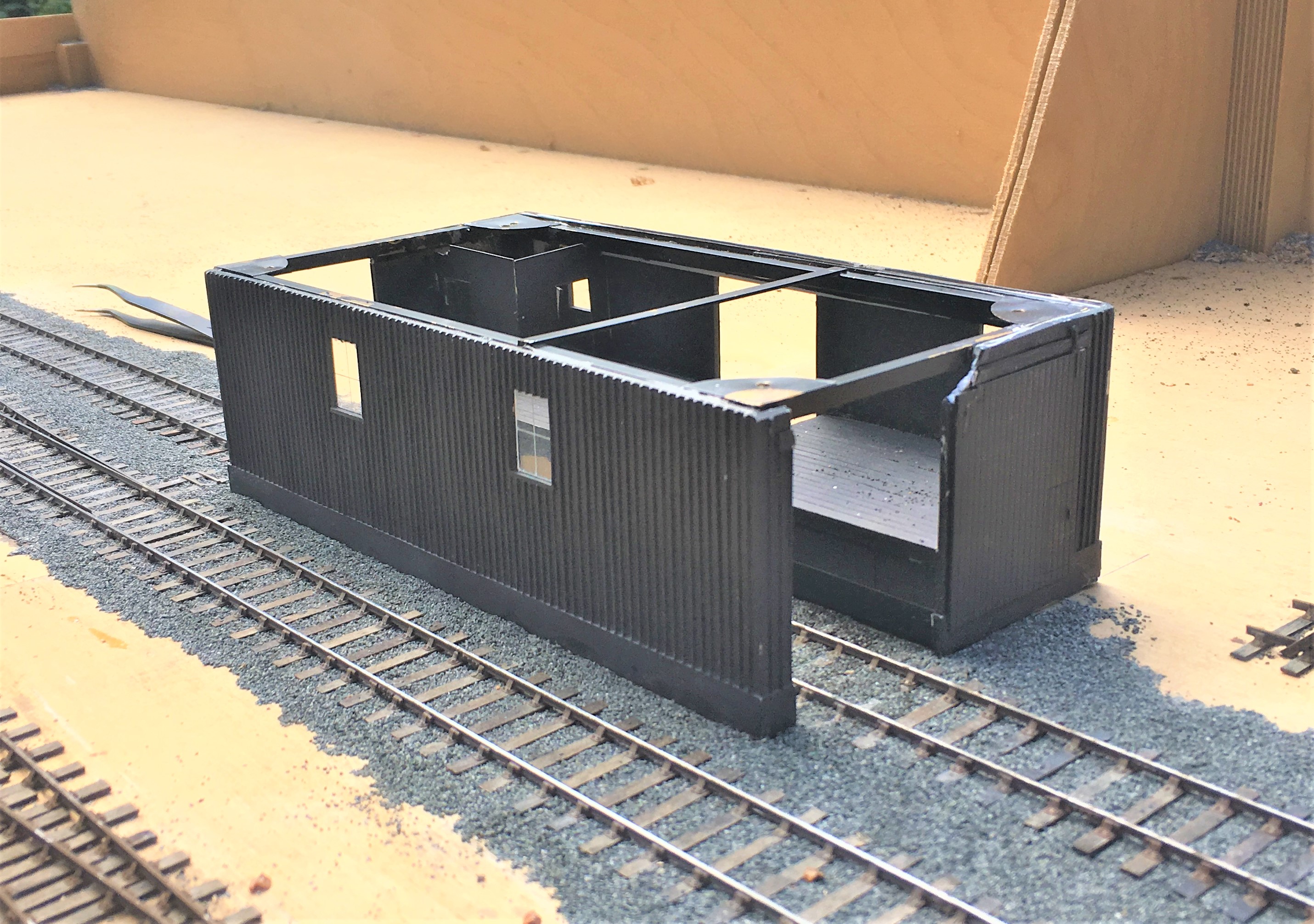
I also to the opportunity to install gutters and downpipes; something I had been meaning to do since I was 17………a bit of a shameful shortfall, given I am a chartered building surveyor!
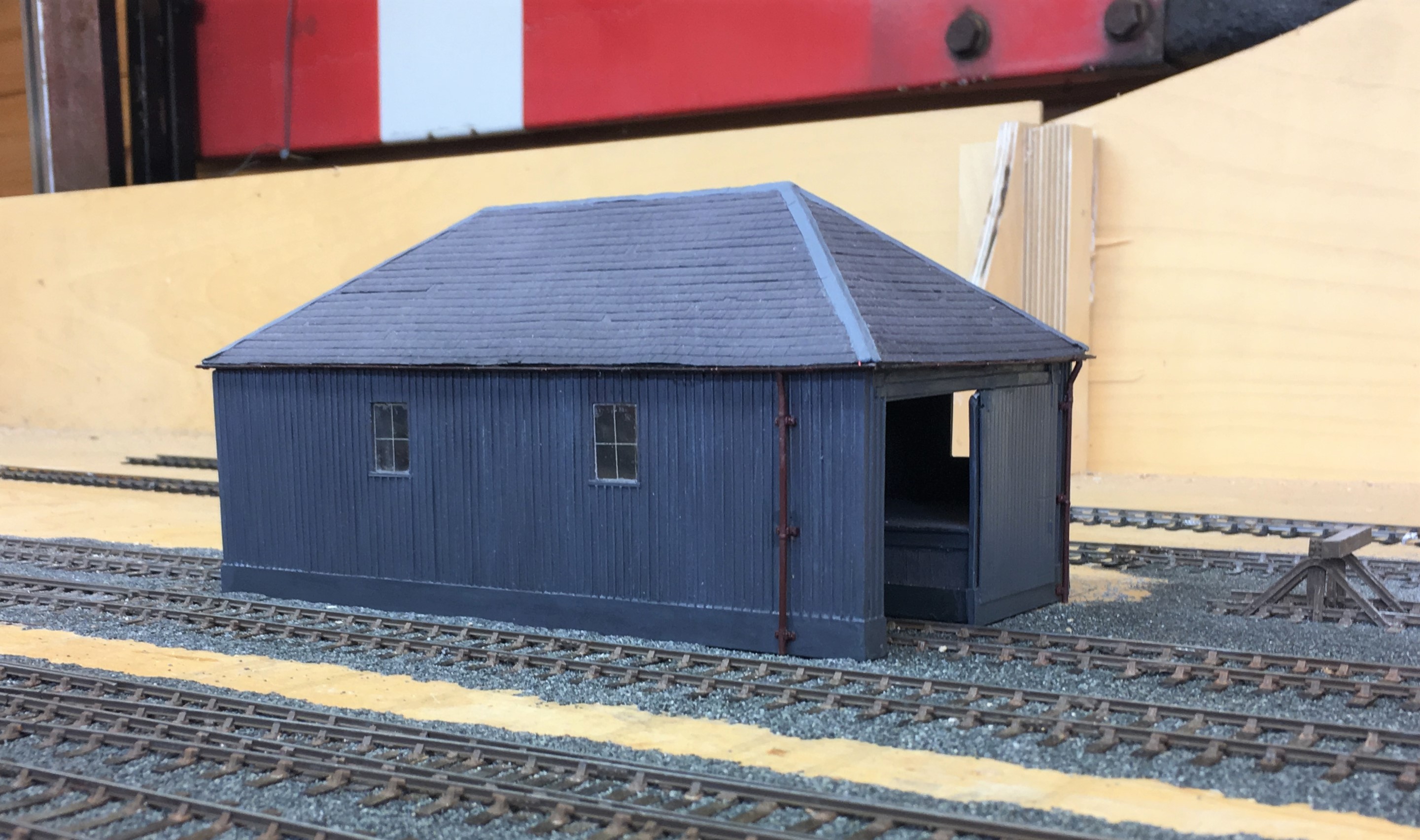
I am pleased with the results and the model is now much more robust so it should do at least another 36 shows! Whether its owner can will be kept under review!
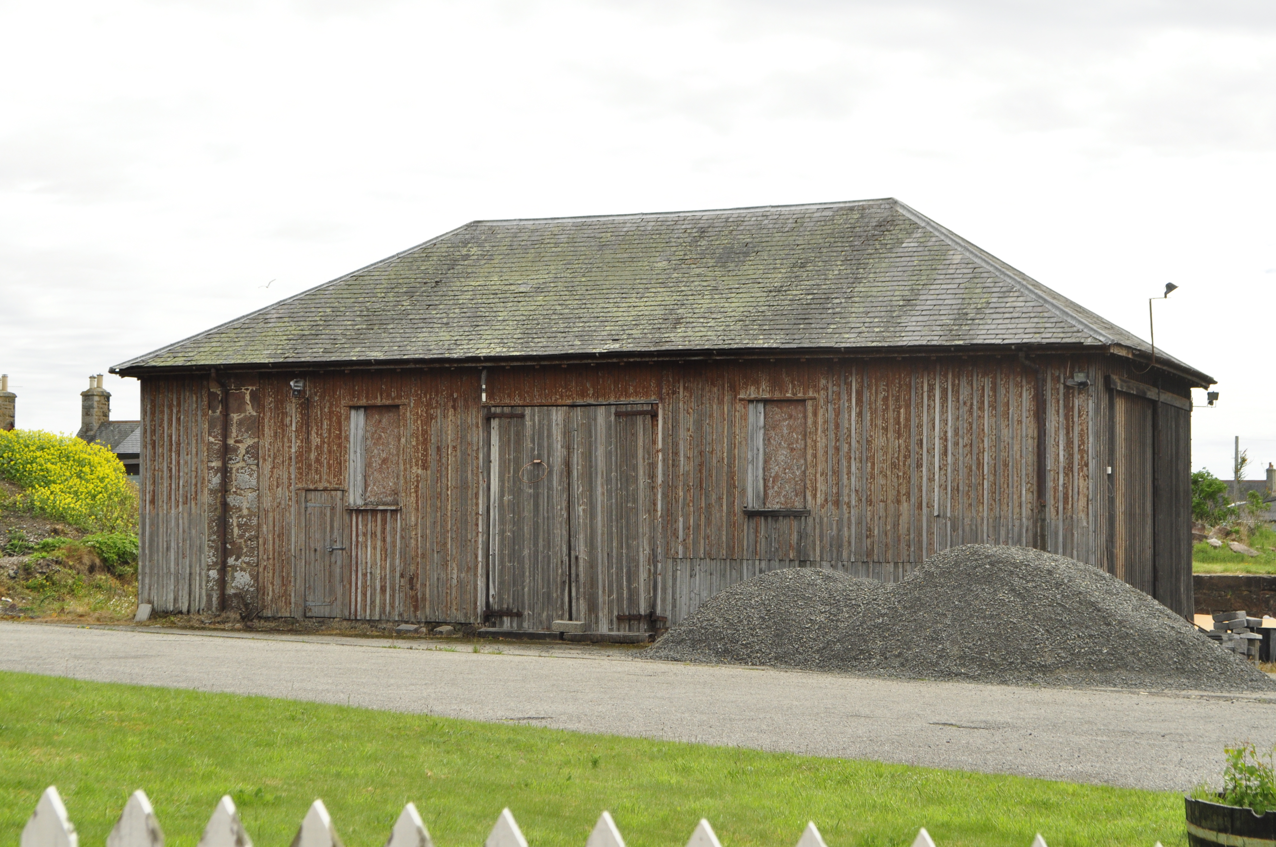
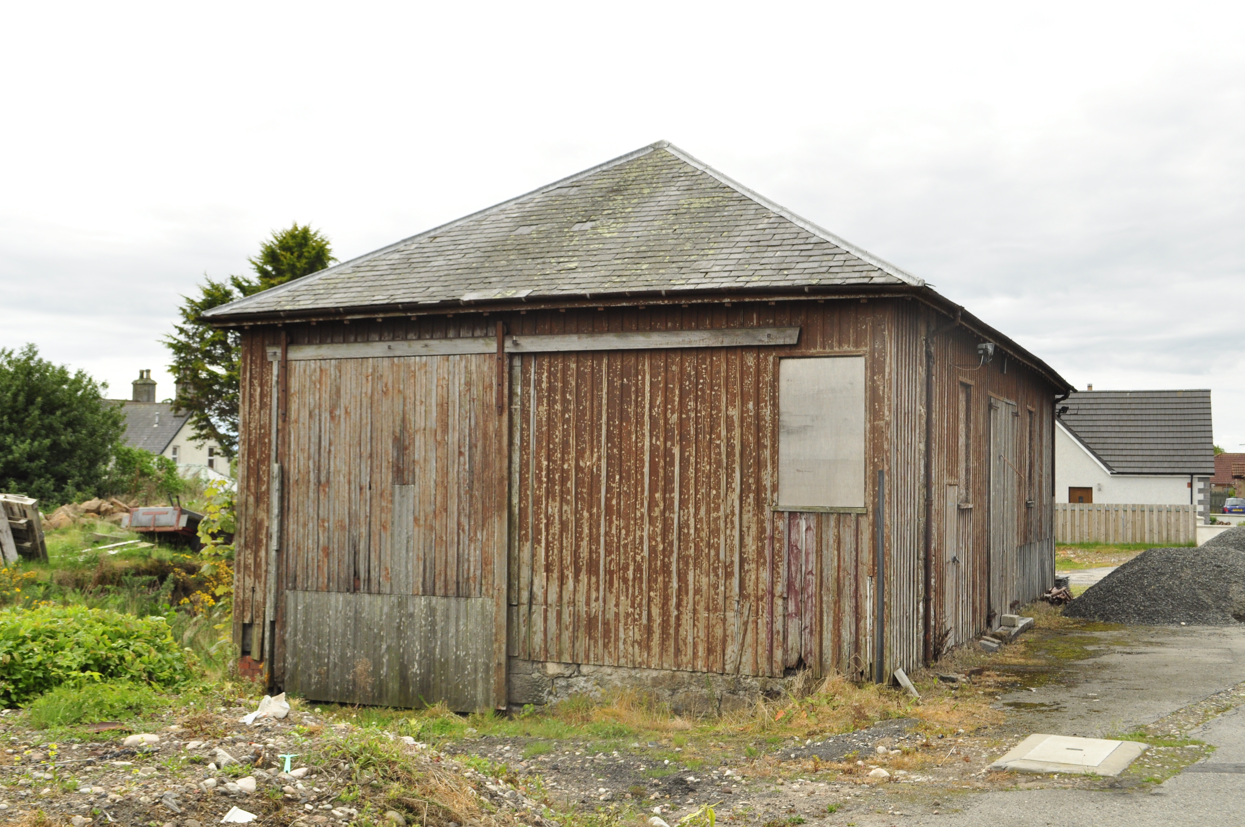
My goods shed is based on the Orbach drawings of the shed at Garve (the August 1952 edition of the Model Railway News). The prototype was swept away in the 1970s and whilst there are a pair of the smaller sheds still remaining (notably at Brora), there are no longer any of the standard Highland Goods sheds left. The last to go was in Golspie about two years ago and I did manage to both photograph and measure it before it went. Here are some views of it before it was demolished:
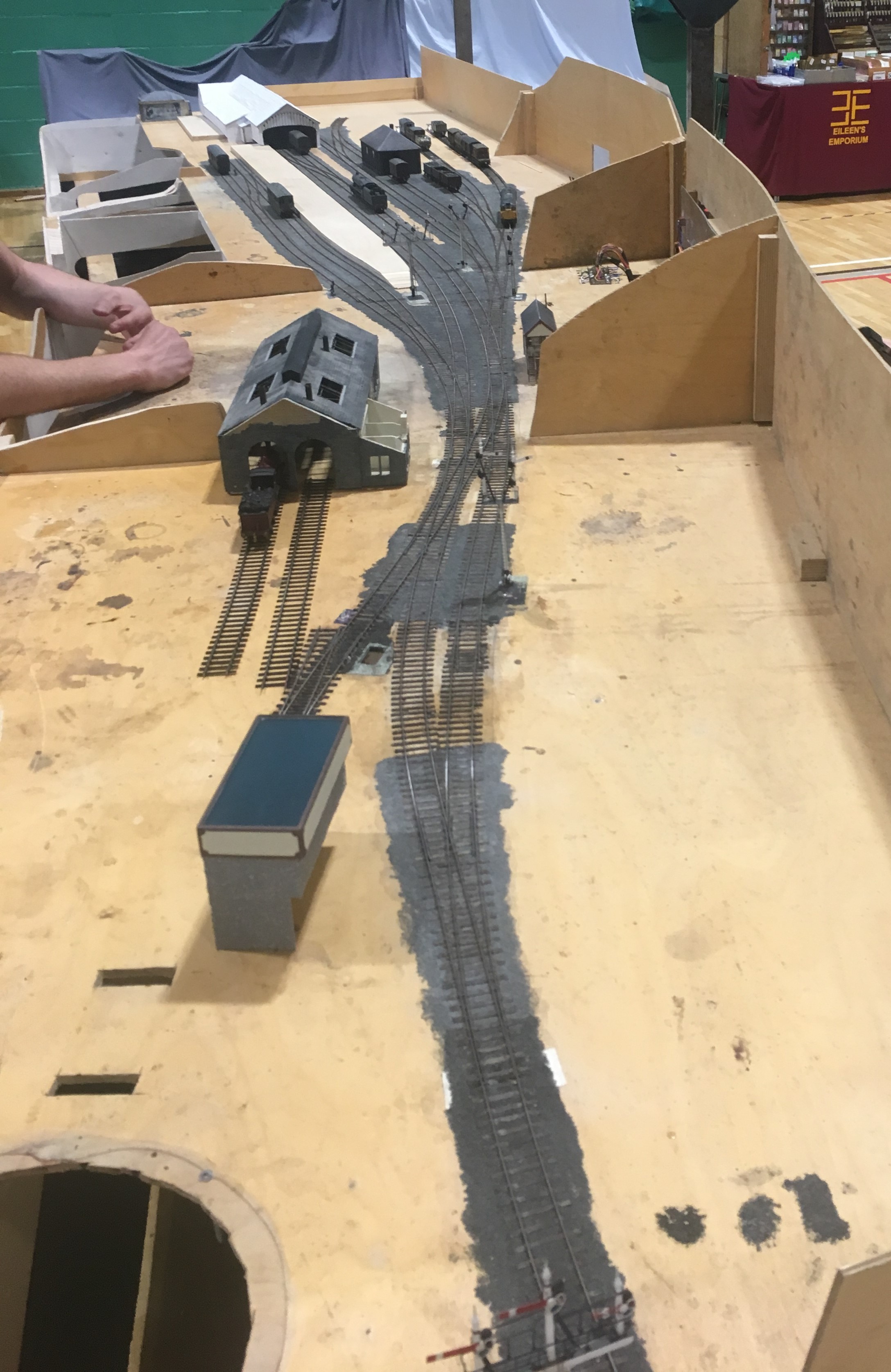
It Lives Igor; the Monster, It Lives……
Well, it is twitching quite a lot anyway……………..
A significant day in the life of Glenmutchkin over this weekend, as I have got a significant proportion of the trackwork which has been laid operational. Admittedly I have an electrical issue in the branch bay (something is wired backwards!), the fiddle yard has not yet been linked to the layout and the single slip still has not be corrected but it works…………..
This is my Loghgorm Bogie (Clyde Bogie series) built by John James. The body is not quite sitting right on it, which is why there is a bit of bouncing; which is a bit worse when it runs faster as below.
Lots to do, but we are getting there! There will be a working layout for Scaleforum!

Golden July for the Highland
A little bit like buses, you wait for a long time for some interesting articles on the Highland Railway and all of a sudden we get two or three come along in the same issue – in this case the July edition of the Railway Modeller. It is a veritable Highland-fest and is well worth buying as a result (no apologies for bias offered!).
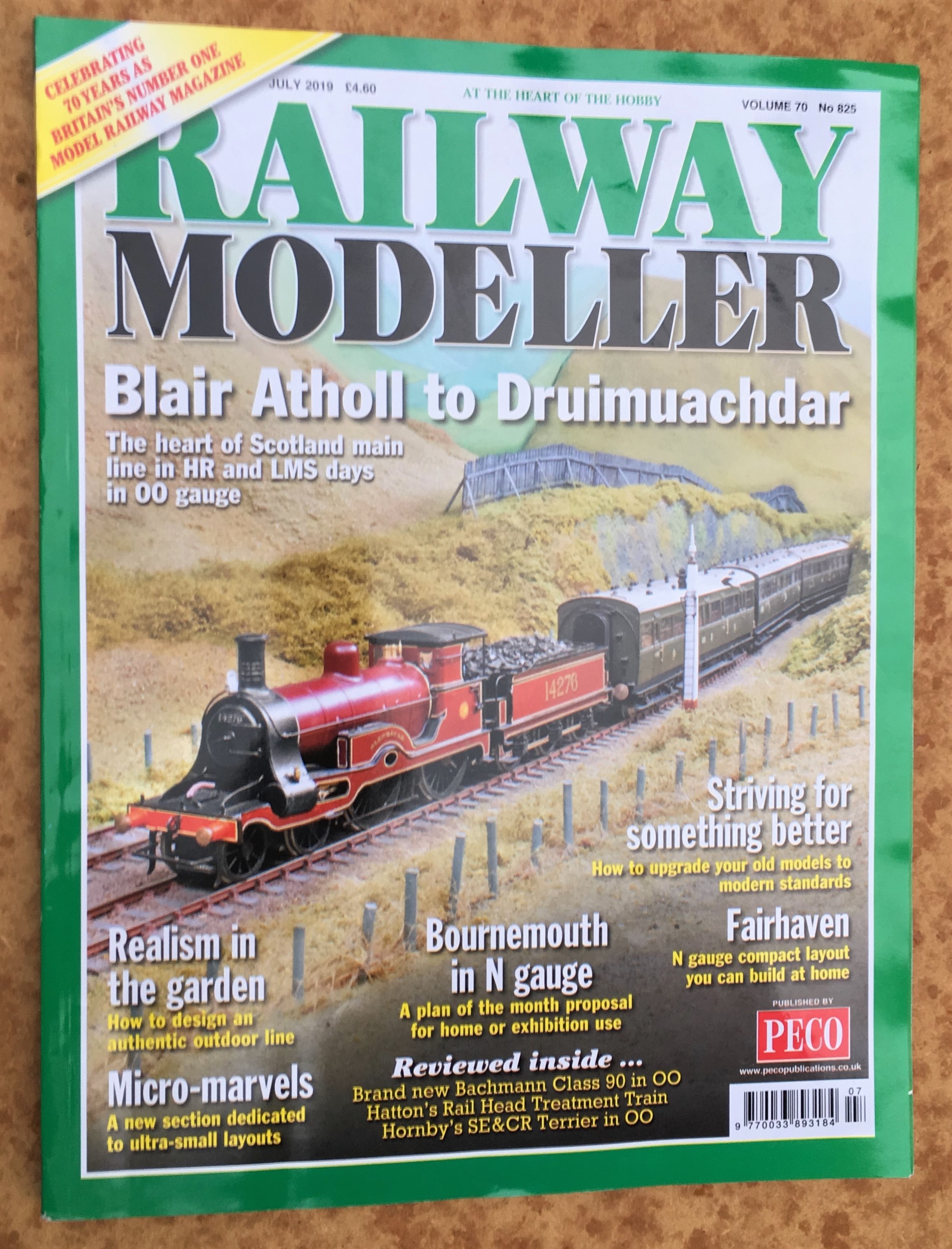
First up the layout of the month is Howard Geddes’ Blair Atholl and Druimuachdar. His layout is a representation of Blair Atholl station along with its approach from the south and the line over the big hill (Druimuachdar as Howard describes it or present day Drumochter). It is liberally illustrated with photographs of the layout and numerous Highland locos – these cover many of the Highland’s locos and also those of the LMS era. Howard has written notes for each of the photographs to illustrate the historical context of the train, the loco of the scene to make this a bit more interesting than the average article in the model railway press.
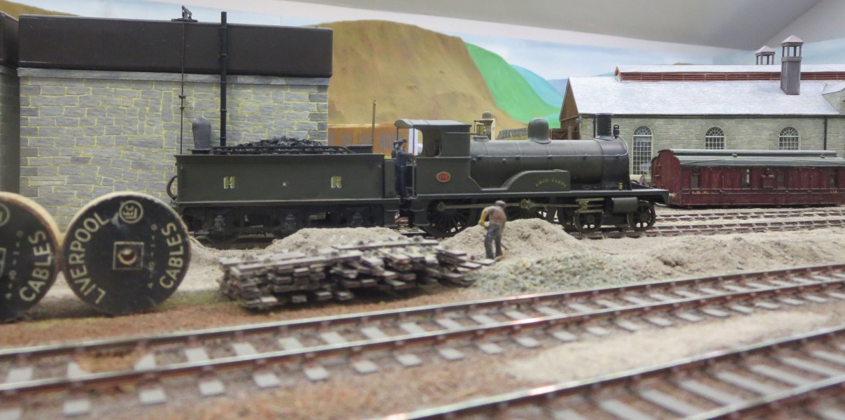
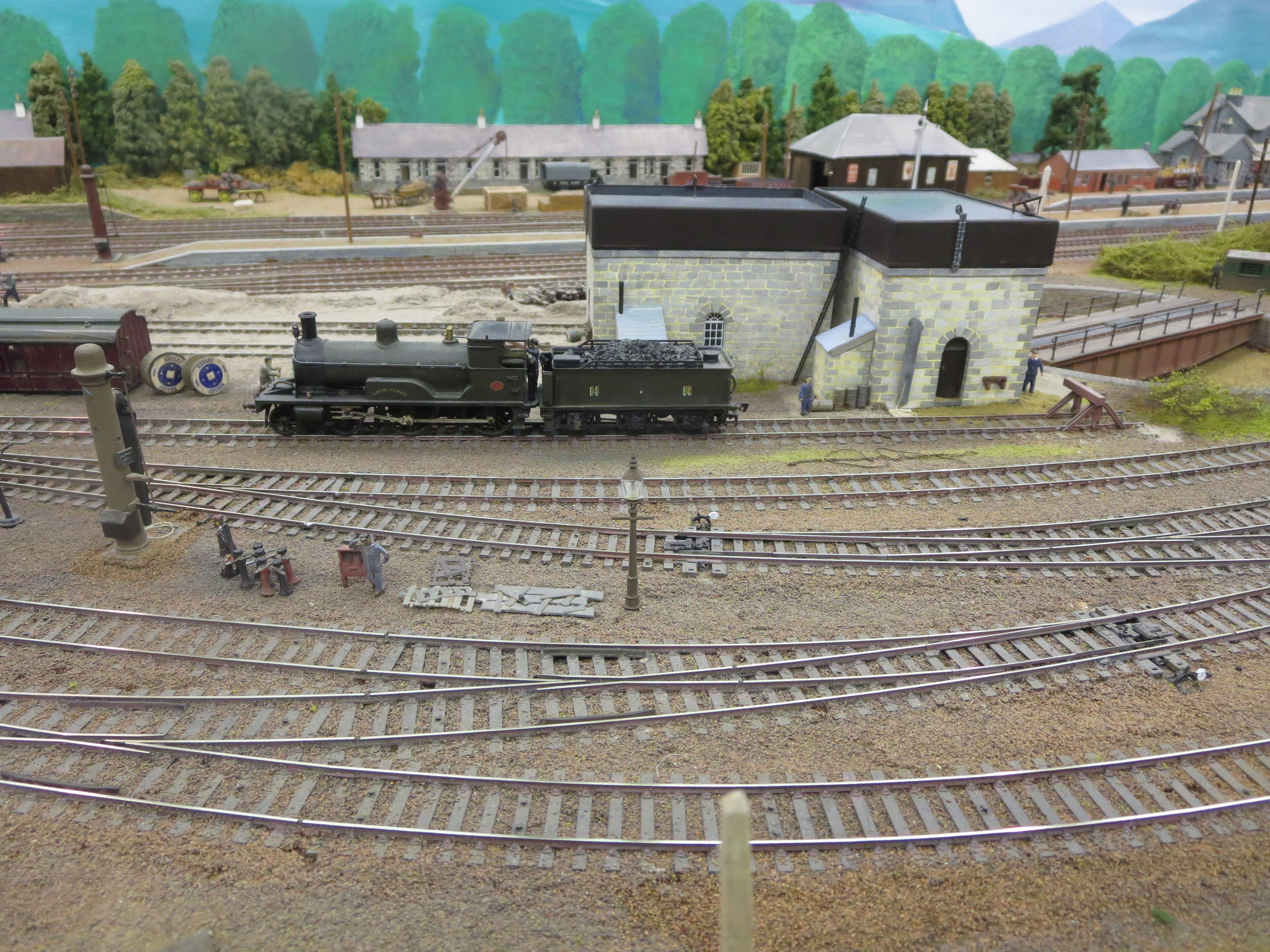
So to emulate Howard, I can tell you that this is a Loch Class, number 127 Loch Garry taking water in front of Blair Atholl’s shed. When built, these were the front line express engines but on the building of later locomotives, they were relegated to slightly less important tasks. So this may well have come off a Blair Atholl local (the all stations stopping services from Perth terminated at Blair) or has just returned from piloting a train up the hill.
The other article of interest for the modeller of the Highland was by Peter Fletcher and was a review of his locomotive fleet for his EM gauge layout Croich (which is based on Tain shed). As he says himself, the layout is really a vehicle to show off his loco fleet and it is fair to say it is fairly extensive and covers the majority of the Highland types in existence in 1920. The article also includes a reprint of a drawing for the small ben class of loco; hopefully a few people may be provoked into
Perhaps the most pleasant part of the two articles is how all but a couple of the locomotives have actually been built! Oh that we see a bit more of this in the mainstream model railway press!
I don’t have any pictures of Peter’s layout so you will need to refer to July’s edition of the Railway Modeller or the March 2018 for the whole layout. Howard has however provided me with a number of photographs of Blair Atholl that weren’t in the magazine to act as a tempter………..
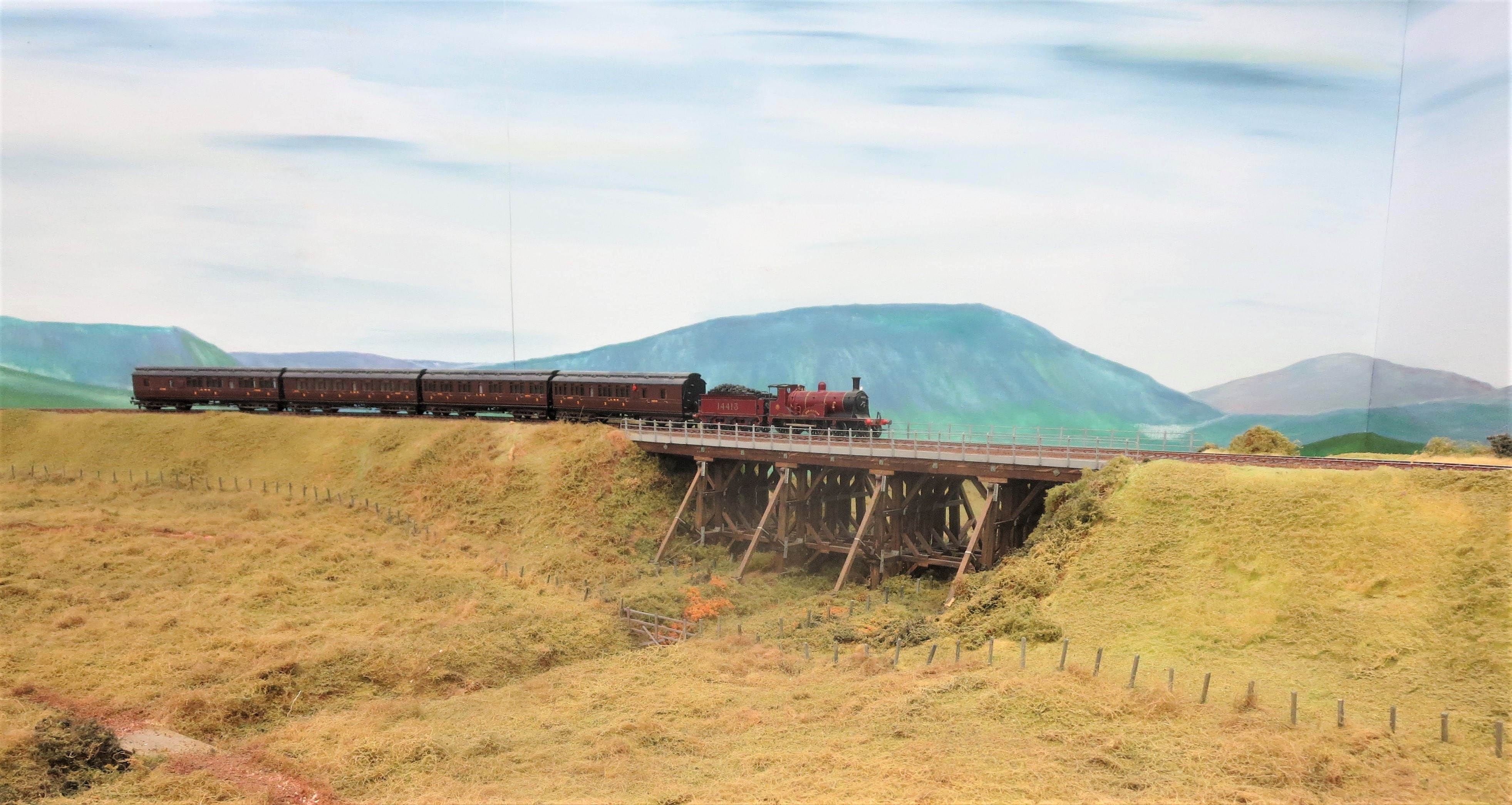
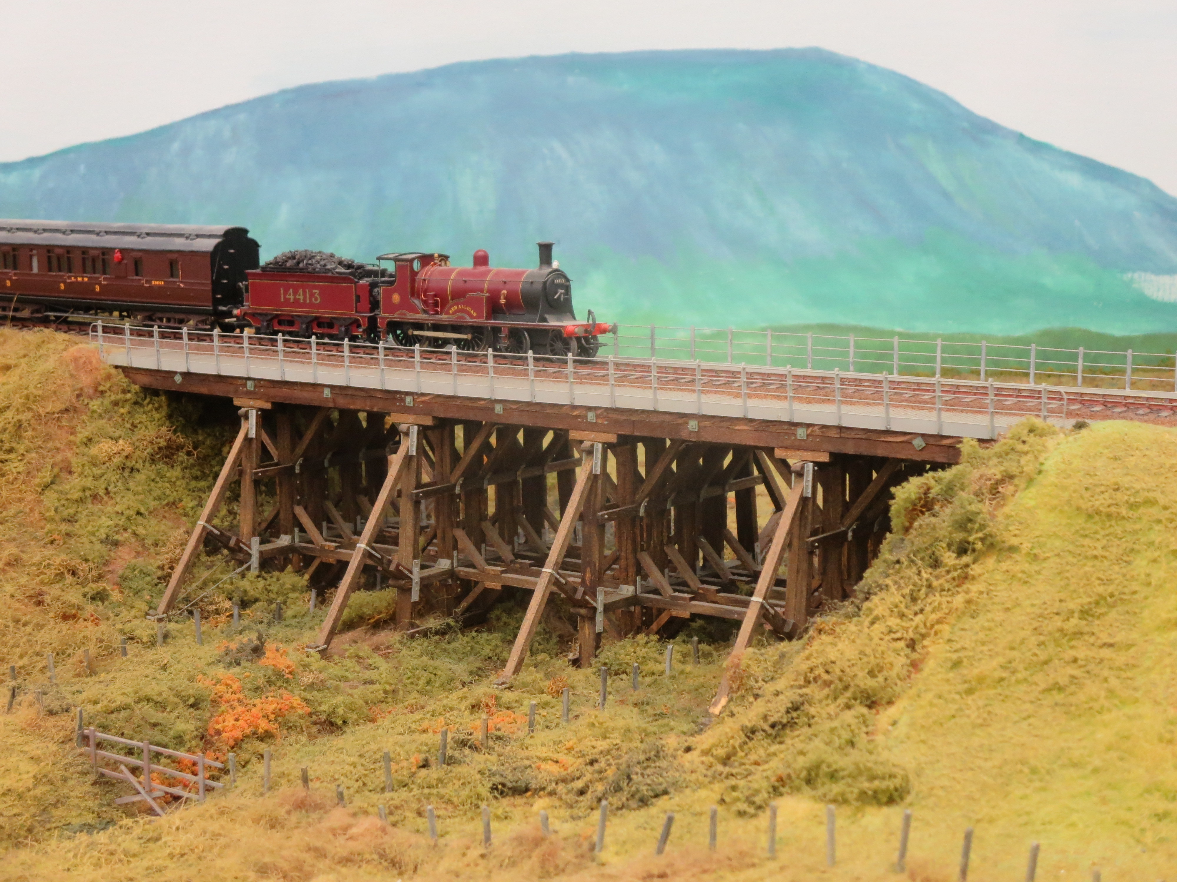
Wee Ben, no 14413, Ben Alligan crossing Howard’s model of Altnaslanach Viaduct (from just north of Moy, and still there albeit in structural terms now merely decoration to a steel replacement that is inserted within it). It is the Highland’s locos in the LMS first livery that float my boat, so this is as good as it gets for me!
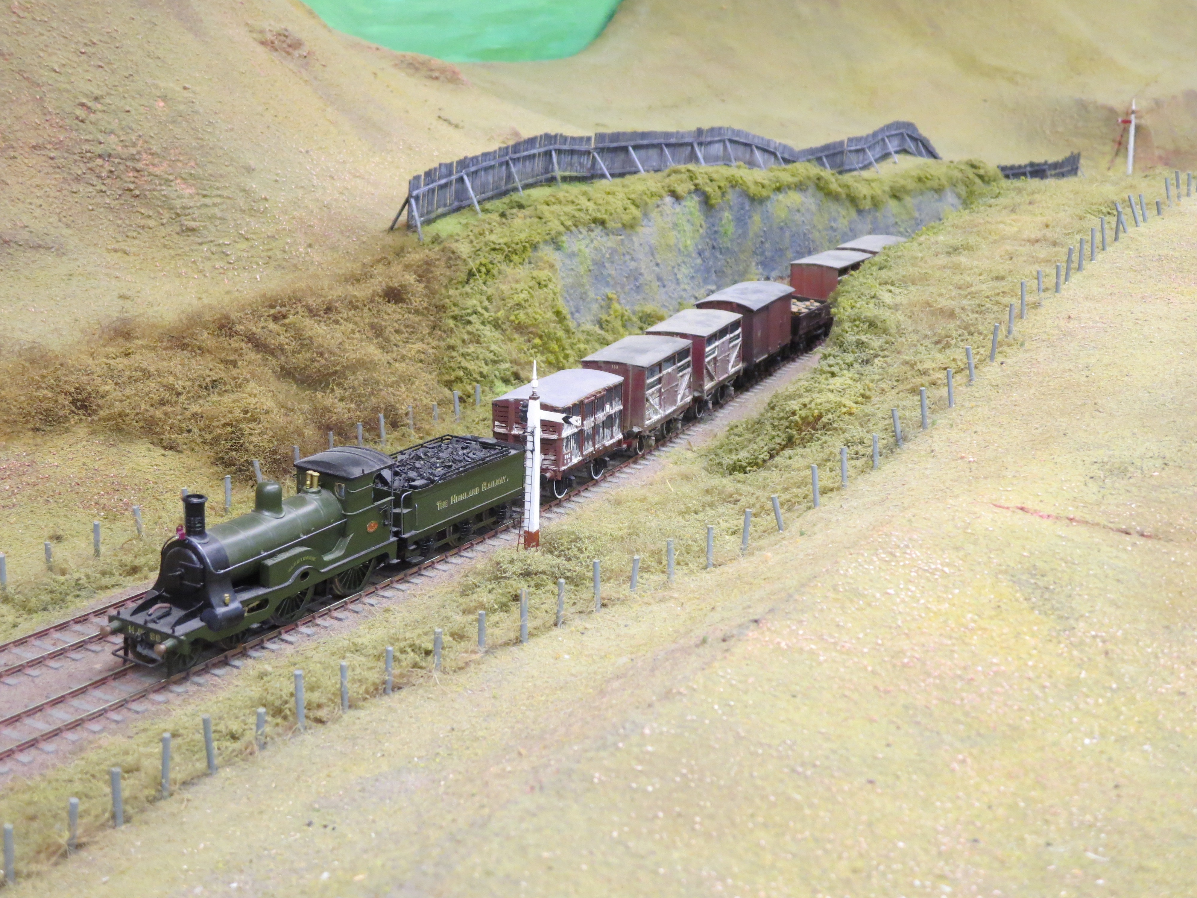
HR’s no 99 Glentromie, one of David Jones’ Strath class with some sheep and cattle wagons at the head of a mix freight train.
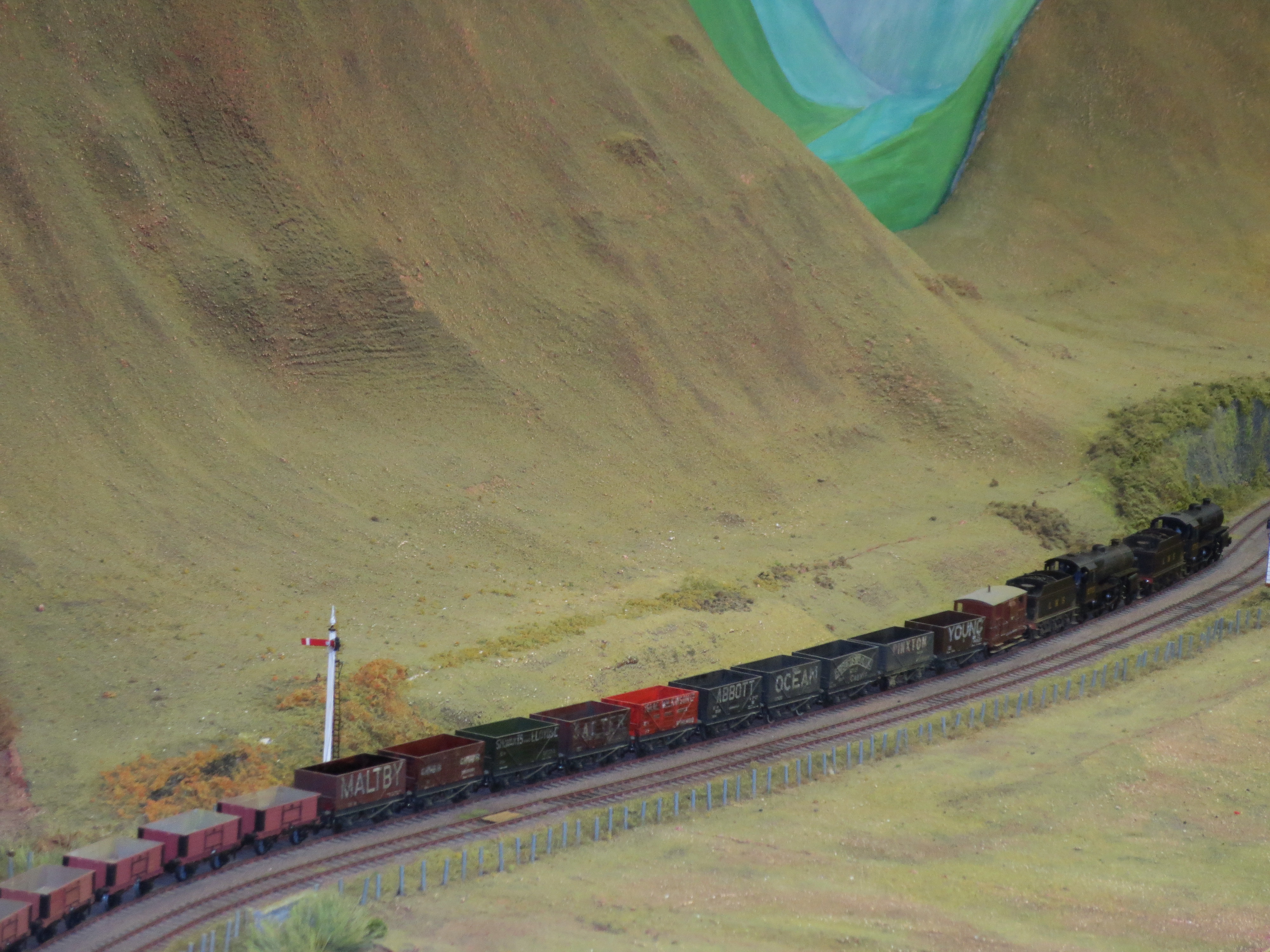
The premier locomotives on the Highland mainline between 1928 and the arrival of the Black 5s in 1934 were the Hughes Crab class – a locomotive that I find the brutishness of which very appealing (I have a couple in progress). Here we have them hauling a freight train through the Druimuachdar portion of Howard’s layout – representing the summit of the line going through the wildness of the Grampian Mountains. I was looking down on the scene only a fortnight ago from one of the adjacent munros looking at the really short HST sets now in use on the mainline!
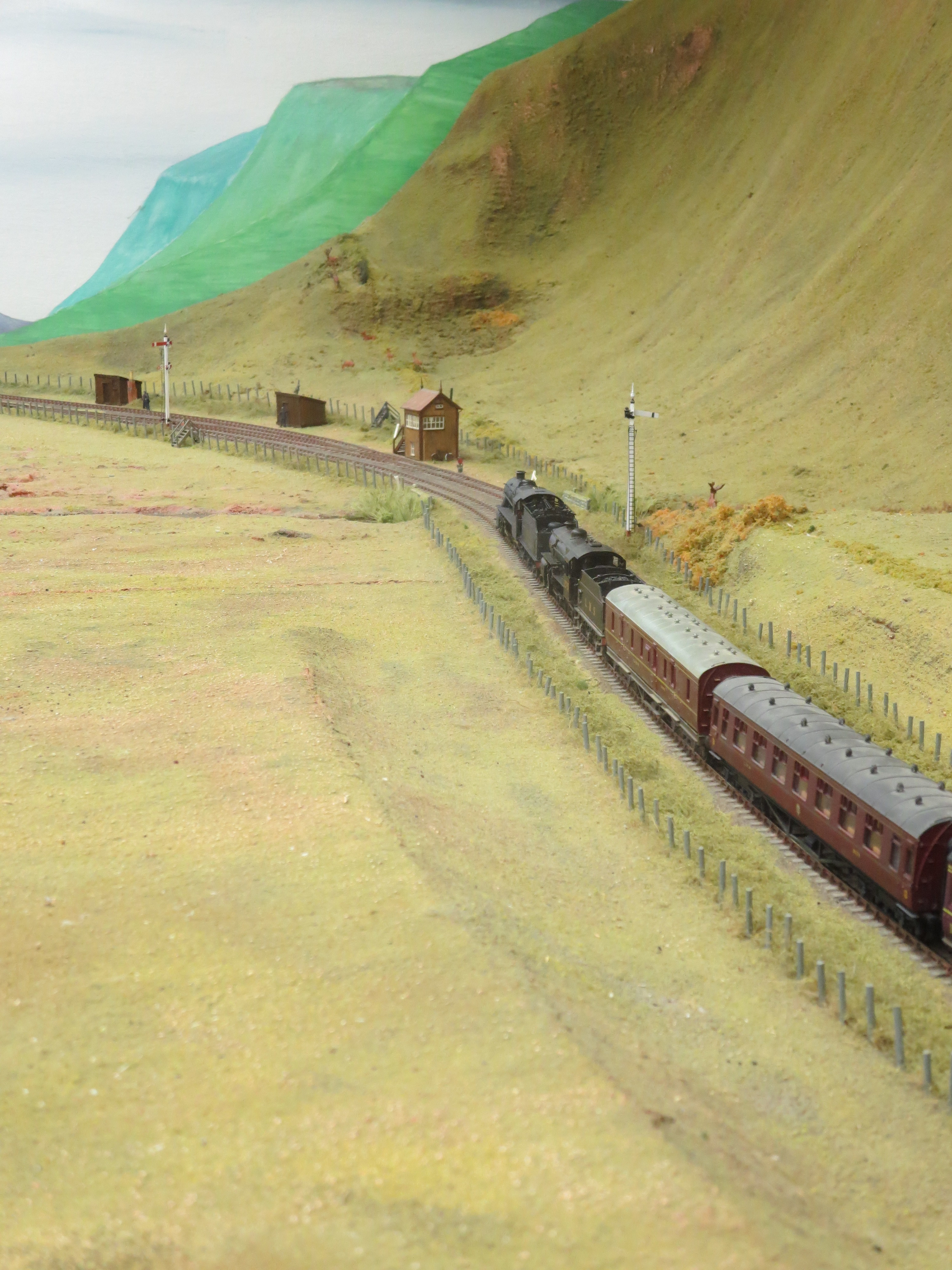
The Hughes crabs again on a more normal passenger travelling in the opposite (northwards) direction.
A vista across the MPD area of Blair Atholl with Loch Garry now taking a breather waiting for its next roster.
The final of the three buses is the announcement of the release of a Highland signal cabin by Peco, as per my previous post.
