Blog Archives

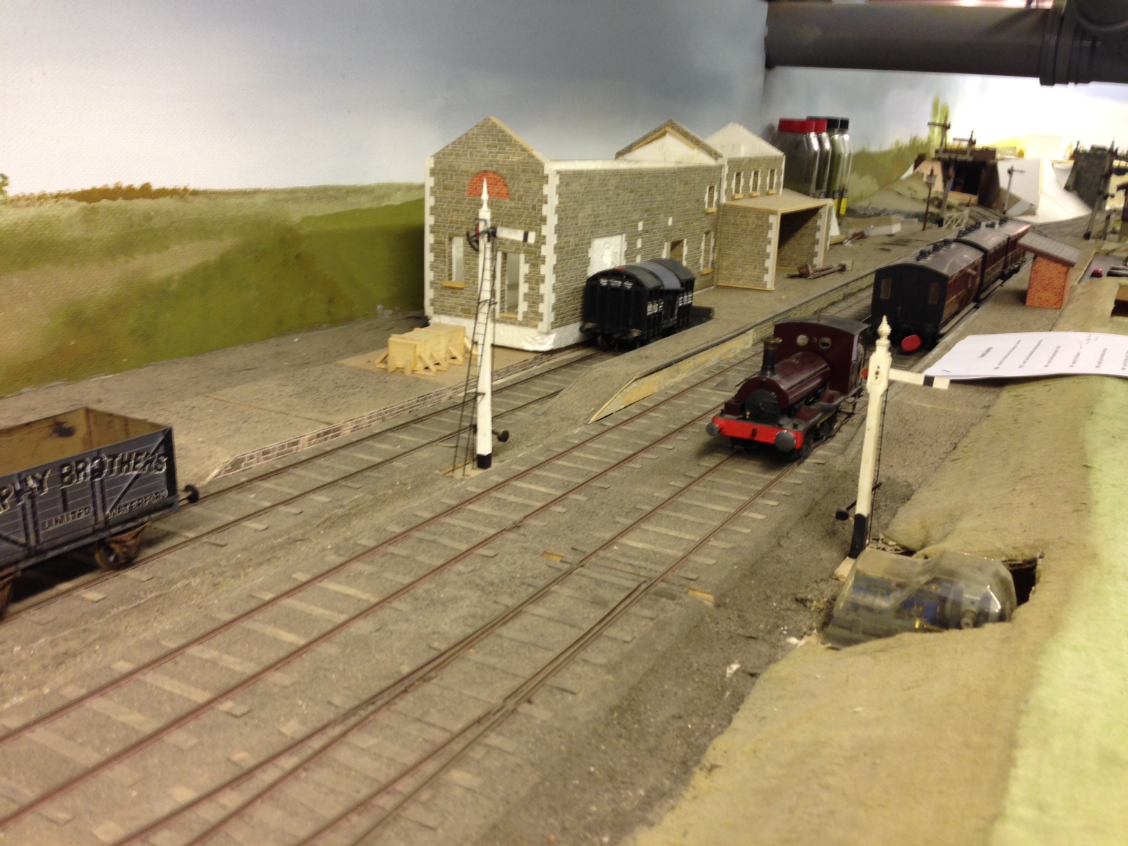
Aultbea Revisit
A year ago, I posted a few photographs of one of my friend’s layouts, Aultbea.
Peter has been making progress with the layout and now has the bulk of the trackwork laid, so it is worth having another look at it:
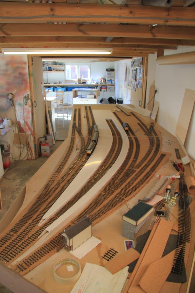
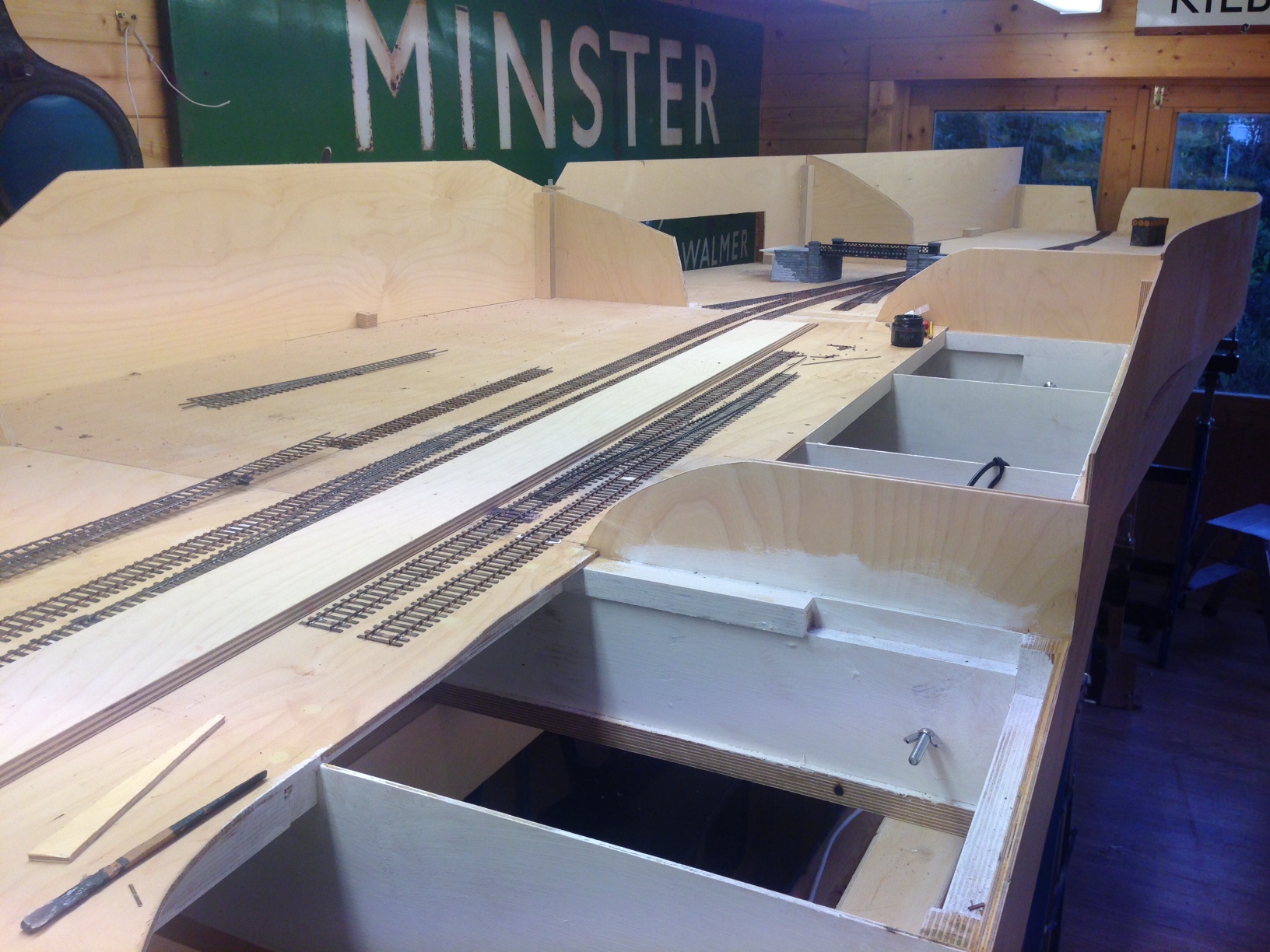
As you can see, it is a bit of a beast because this is only the passenger station complex, the MPD and sidings for the military are not even on show here!
The full extent of the layout can be seen in the previous posting and you will see he that even the bay is conceived for a seven coach train. Looks like Peter will need to be building/converting and otherwise acquiring a fair amount of stock!
in the views you will see that a some of the buildings have been finished – the signal cabin and the water tower. I think station buildings are next and before too long, he will mention signals I suspect!
One for the Gorilla – tracklaying progress
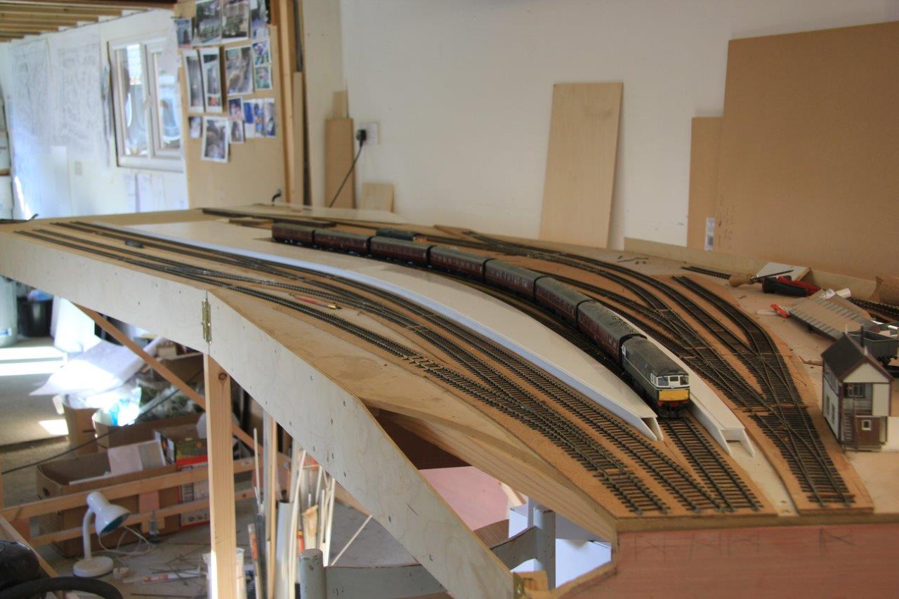
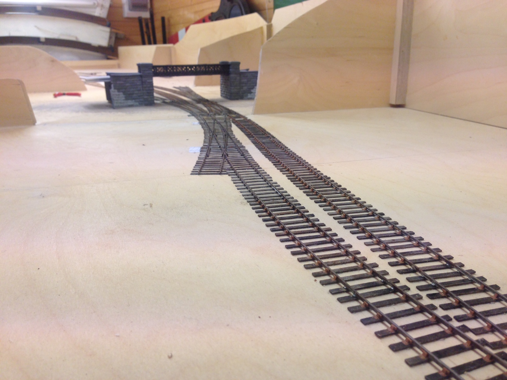
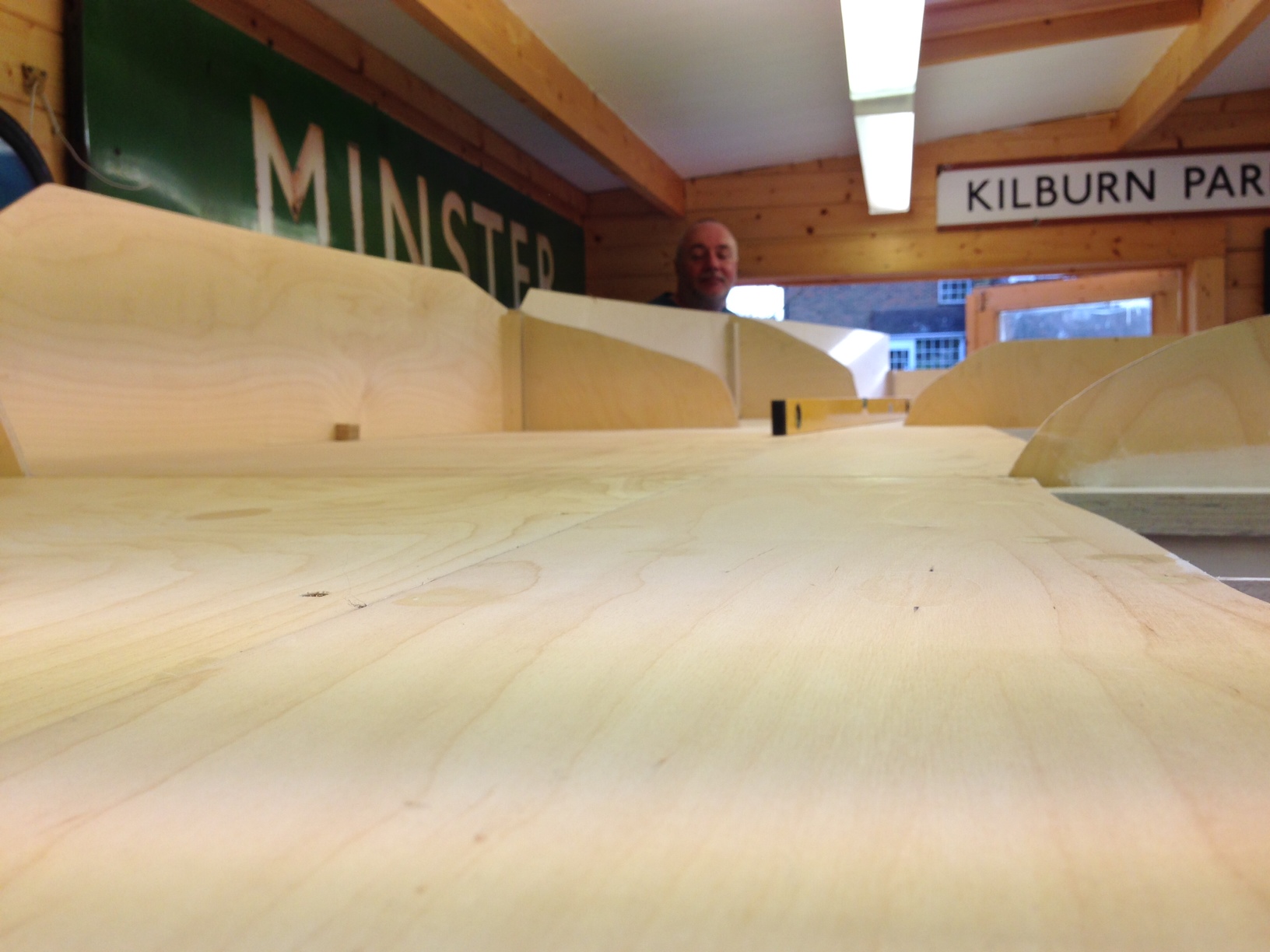
Matters have been progressing with the layout on and off through the summer and a lot more of the track has now been laid. We have both the main line and the full run around loop complete, along with most of the bay and its run around loop too.
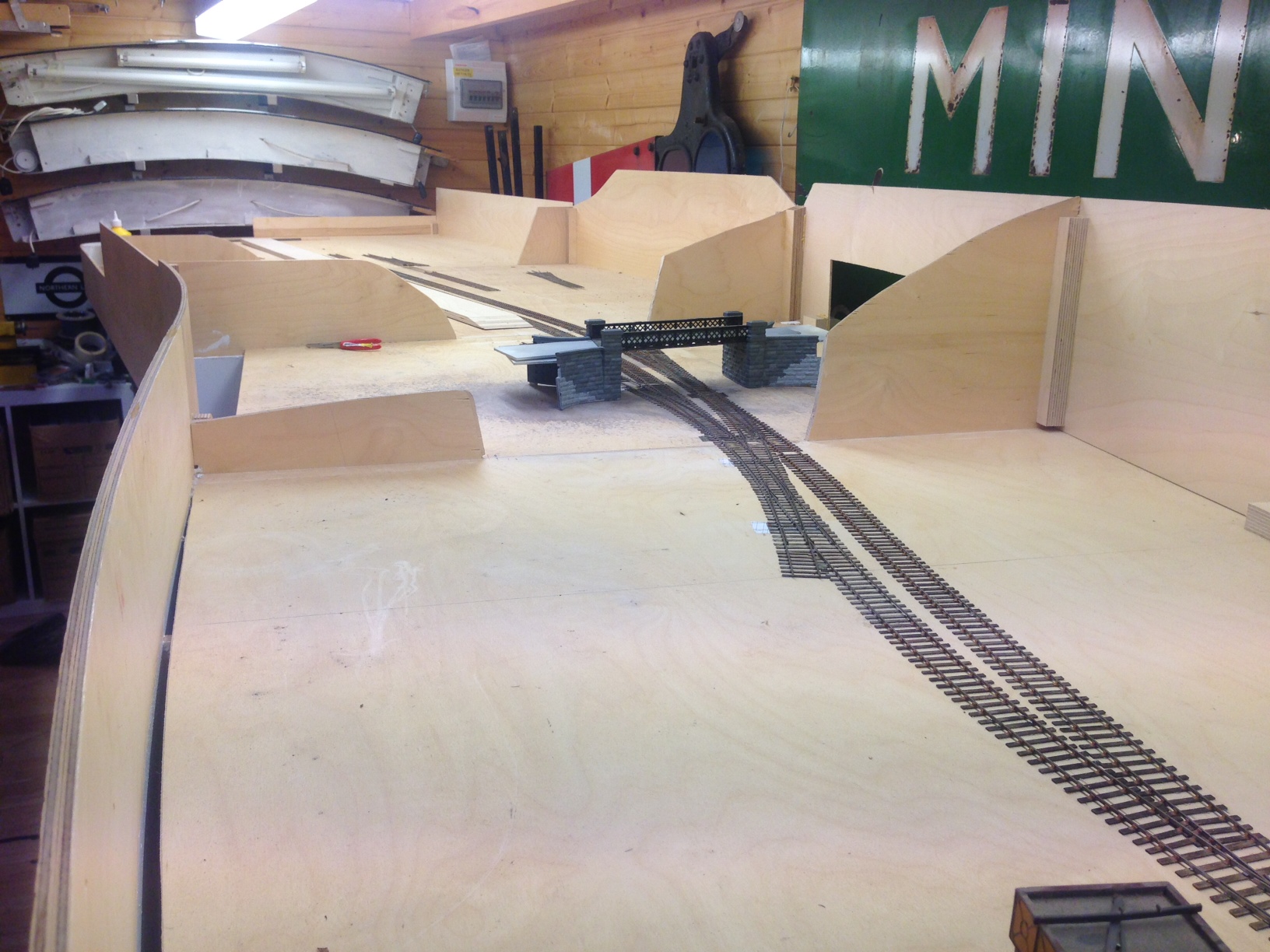
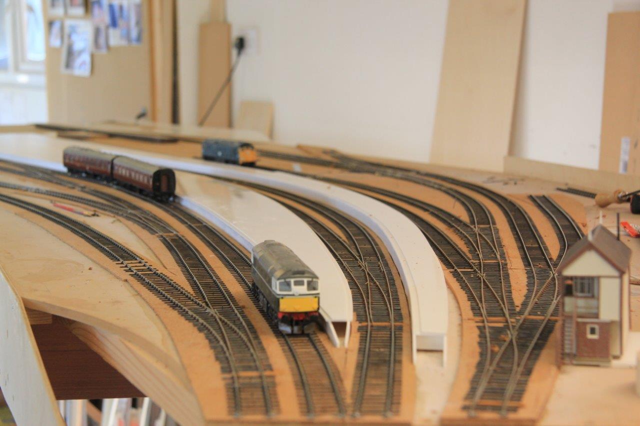
The line diverging in the foreground is going into the shed area, those visible below the bridge go to the bay (left) and yard (right). A signalling trackplan can be found here.
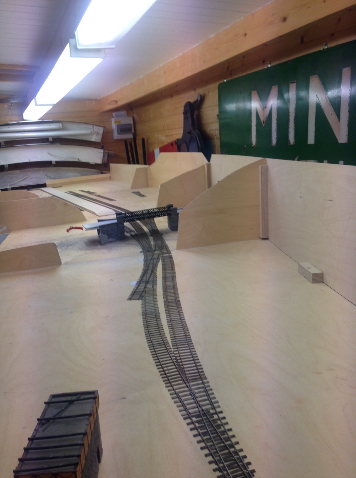
I quite like the sinuousness of the line, which can be seen here/ I have done this in order to give interest to the layoput but it is pretty typical (indeed characteristic) of the lines to the west coast as they wind through the mountainside. I do have in mind some hills to justify this in the finished item.
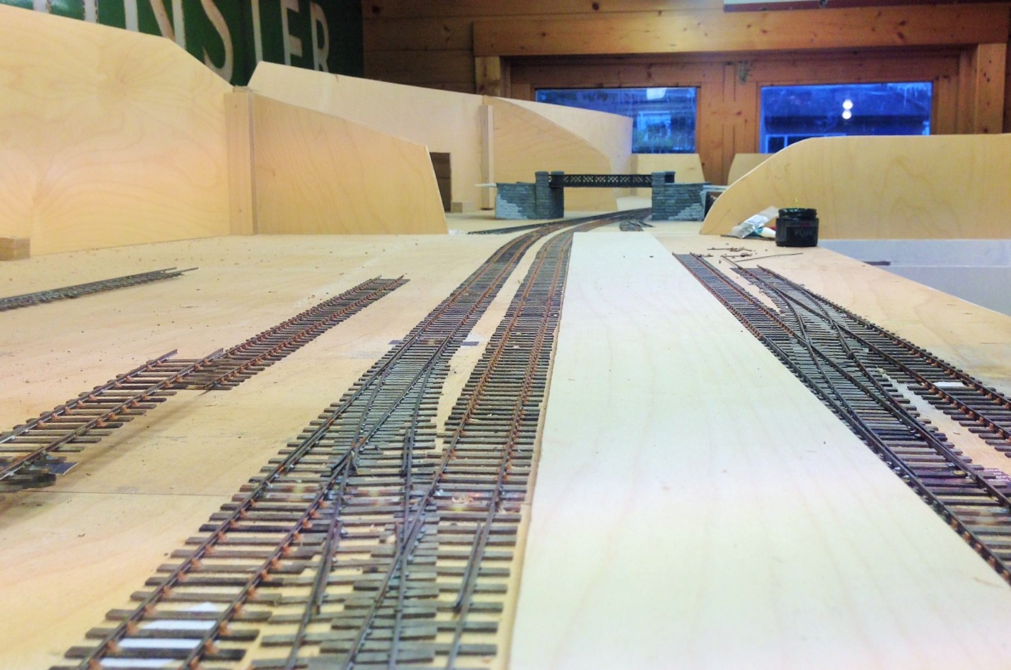
Already there is a sense of magnitude to the station forming, the platform face (which is not all in view in either of these views, comes in at about 7 feet – enough for an eight coach train of pre-grouping coaching stock. Really, its length is defined by the length of the bay – this will become clearer when the train shed appears because the bay has to start clear of this..
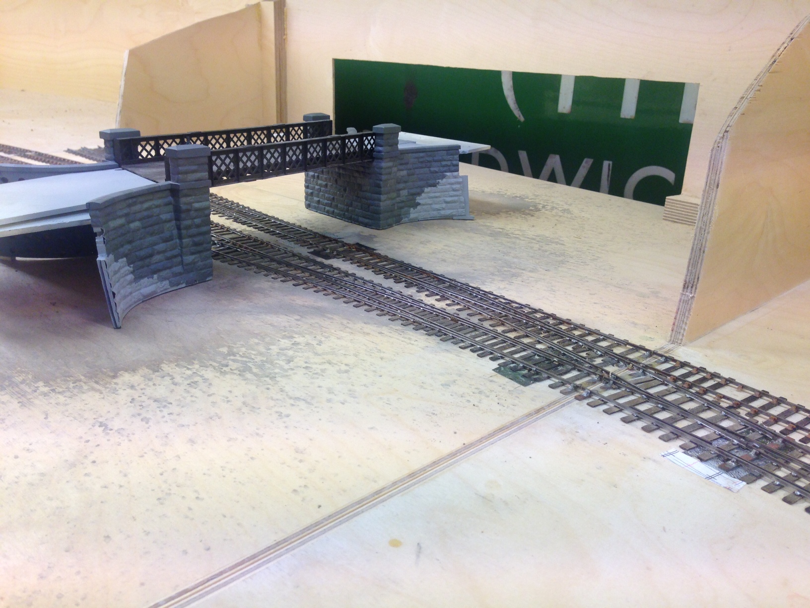
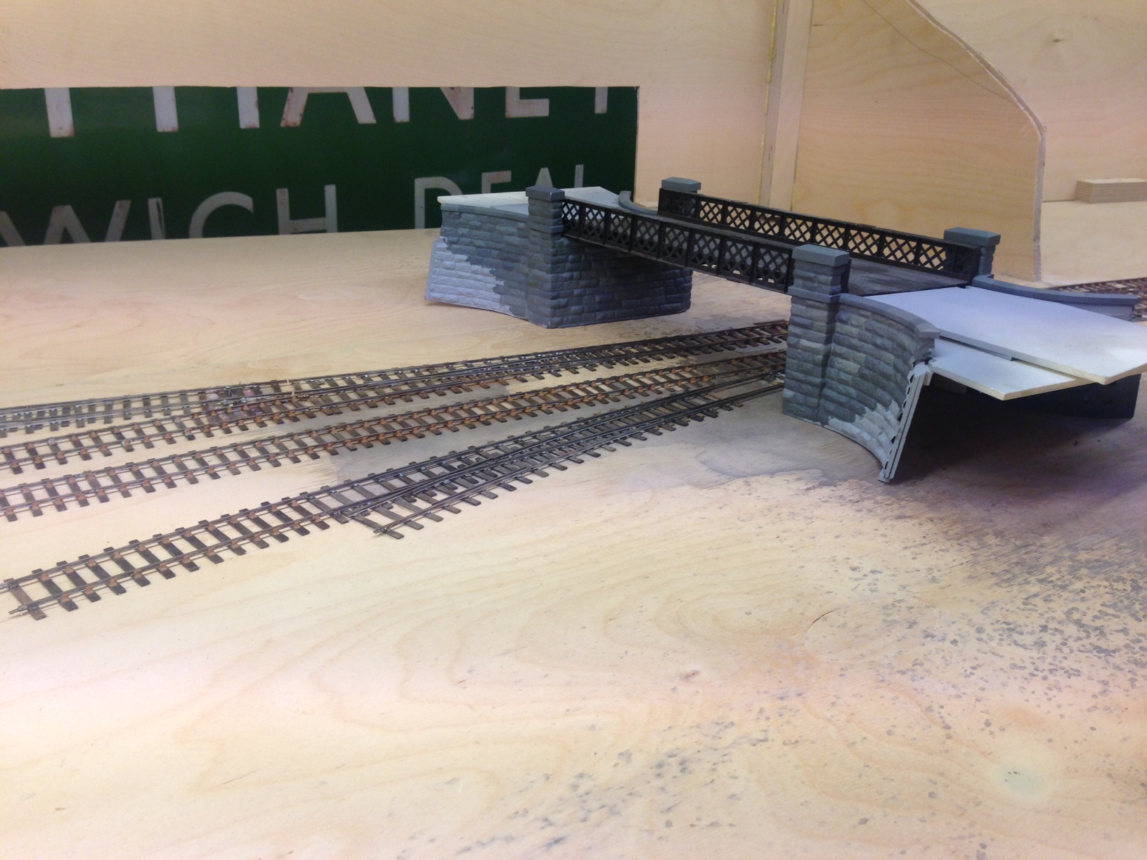
I have also placed into its approximate position the road overbridge that separates the shed from the main station area. The construction of this can be seen in postings here and here. The intention of hte bridge is to act as a scene blocker and thus to compel the watcher to view the layout from more than one location to appreciate it.
The Cruellest Cut – Carrying on with Hornby’s Gresley Buffet
The first task in dealing with ready to run vehicles is to work out how to get into them – not always as easy as it sounds! In this case, this is achieved by slipping finger nails between the sides and the underframe solebars; this releases four catches and the top pops off. The interior then slips out without bother but the glazing is a little more tricky as it is secured with some very gooey glue. Whilst this releases the perspex relatively easily, it was difficult to then remove the remaining glue – I found it best to do this by rolling it with a thumb and accumulating the residue on a scrap of paper but it was a pain getting it all off.
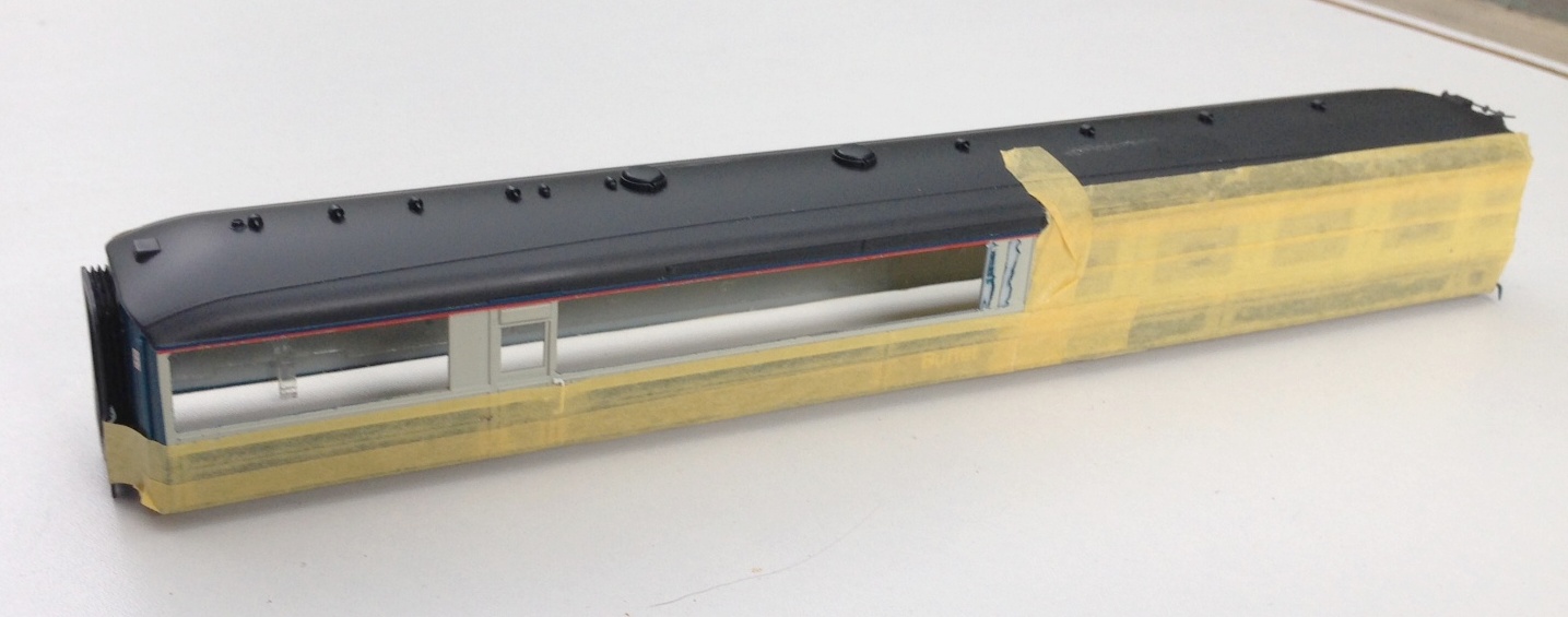
Prior to attacking the model with knife and blade, a sensible precaution is to protected all of the areas that are not to be cut with masking tape, which you will see I have done. This was effective but I did find that I dislodged a filler pipe when I removed it, so perhaps a slip of paper over these would be prudent next time.
Then it was time to get cutting; I varied between using a razor saw and a scalpel to cut a grove by using parallel cuts but in both cases it is important to cut to the waste side of the finished line. I found that it was best to work to an existing bead line, even though when working to the saloon end of the coach the bead was the side of door jamb (this is where I found the knife best and I made sure this was one of the first cuts to be made) so that there was no stress on the thin piece of material. By the time the cutting had been finished the holes were quite big!
Nearly all the cutting done now; but the last panel to the right did also get cut away
It pays to dress the sides of the opening with care so that they are straight and square as this makes the fitting of the infill pieces much easier. These should be cut fractionally over large and then sanded back by small degrees checking regularly to determine if it fits and taking care to ensure that the square/straight edges are maintained. Once it fits, I let it into the hole and secured with butonone and then left it to cure for a couple of hours so that I did not disturb it when I subsequently fitted the beading. This was formed with 0.2 * 0.2mm microstrip and these needed to be set out with considerable care – aided by the use of venier calipers – to get them regularly spaced and vertical. Even the most minor of inconsistencies detract from the affect.
Replacement panels now in place, including a partial infill of the window by the door
Next up was the removal of the various roof vents and cowls as these too changed. I suspect that these were no consistent across differing vehicles and it is quite difficult to determine what goes where but I was assisted by some photographs from here. Utilising some of the vents salvaged from the Hornby model and also from Comet Models, the latter generally with their shields filed away as the roof views I have have straight flanges as shields – which I formed with brass strip as I though plasticard would be knocked off.
Roof vents in place, based on a photograph of the roof of 9132 at SRPS in the 1970s. I also noted that the alarm gear on the roof was at the other end of the vehicle in comparison to the Hornby model, so this is going to need to be cut away and recreated at the opposite end.
Dinner Time – A Gresley Buffet for Portchullin
Whilst my memories of the former HR’s line from the 1970s and early 80’s only ever had BR mk1s as coaching stock, there were occasional strays coming onto the line in the form of Thompson/Stanier full brakes and Gresley buffet cars. As I understand it, a pair of the latter were indeed the regulars on Glasgow to Inverness trains. So, wishing to enliven my passenger trains up a little on Portchullin, I thought that it was time that the punters had a buffet car to buy that notorious rock hard pork pie in!
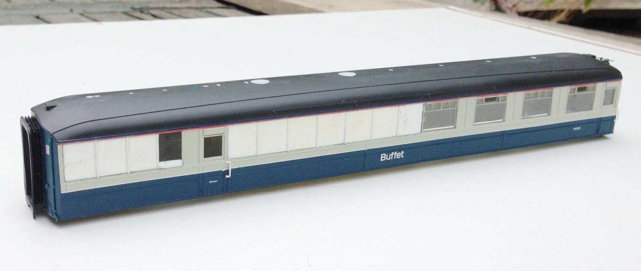
Hornby introduced a range of Gresley stock some ten years or so ago and they represented a significant step forward in terms of quality of coaching stock generally and particularly in comparison with their predecessors. If I recall correctly there were some problems with the direction of the graining that Hornby quite quickly sorted out and the teak coaches look the part – especially as to do them oneself is a very challenging exercise. The only vehicle that they offer in blue/grey is the buffet and this is what it looks like.

As with nearly all r-t-r models now a days, the finish is exemplary and at first glance it definitely looks the part, capturing the curves at the roof very well and it will stand out nicely in comparison with the remainder of the coaches on Portchullin. It is true that the panelling cover beads are a bit thick, which is not visible on the teak finished coaches due to the graining but is rather more visible on the grey here but as I am going to weather down this vehicle to a fairly battered condition, I am hoping this will fade to a lessor impact. Some commentators criticise the tumblehome being too slight and the bogies being subtly incorrect but I am struggling to see either defect so will ignore these points.
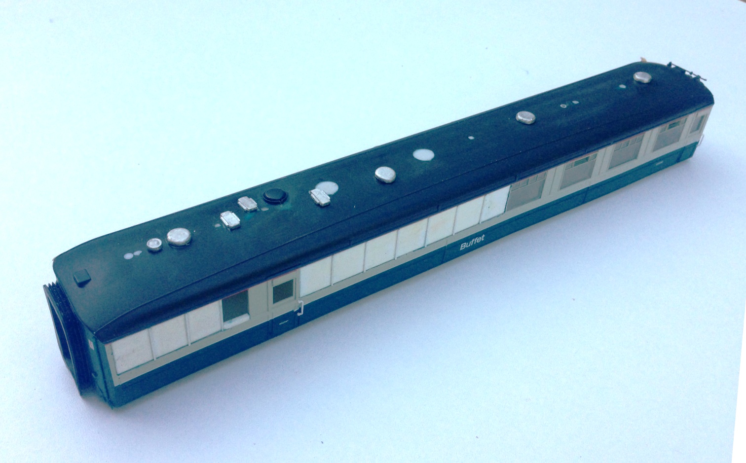
What I will not be ignoring, however, is the most significant problem with the model. These vehicles only made it into the 1970s because they underwent a fairly significant rebuild in the 1950s. Hornby have simply painted their LNER era model in blue/grey whereas the rebuild affected their appearance on one side quite significantly. Here is a comparison and you can see that three windows have disappeared altogether, the panelling arrangement on the near end is different and the roof vents were adjusted to accommodate the revised internal arrangement.


I have seen moans on the forums about this error and even moans from people at the people who are moaning. I make no criticism of Hornby at all; it is obvious that the revised tooling that would have been necessary to correct this would have made the model uneconomic. Therefore, we have to either accept it is as it is or pick up our tools to correct it. I make model railways to do simply that, make them and I derive the greater proportion of my satisfaction from building or modifying things – thus I simply see this as part of the pleasure!
So my next project will be a bit of plastic surgery on an old lady, to get her looking proper! I do not propose to do a full respray so it is not that difficult to do; so to both the moaners and the moaners at the moaners, I would simply encourage you to pick up your knives to follow suit!
Thank you to Hornby for providing the base model and also for the use of the colour photos. The prototype photograph is courtesy of Paul Barlett.
Transfer Update
Back in November 2013, I hinted that I was trying to crack transfers for the Highland’s locos in LMS days; something that is not realistically available via other sources and there does not seem to be much prospect of anyone else doing them.
Anyway, hopefully, I have cracked all I need to with regard to these and the final artwork is complete. This is what it looks like – hopefully it has covered all the locos you might fancy!
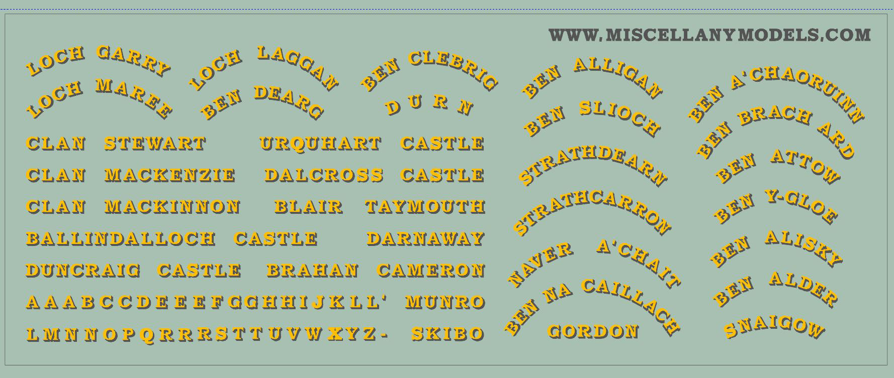
Also on the sheet are one or two other things; but I am less certain that these will work so I’ll keep these as a secret until I find out.
The intention is that these will be available in 4mm & 7mm scales; pricing to be confirmed but I am afraid they will be fairly expensive as the production run is not big and you 7mm chaps in particular eat the page with the size of the prints!
Once they come in, I decide whether they are viable.
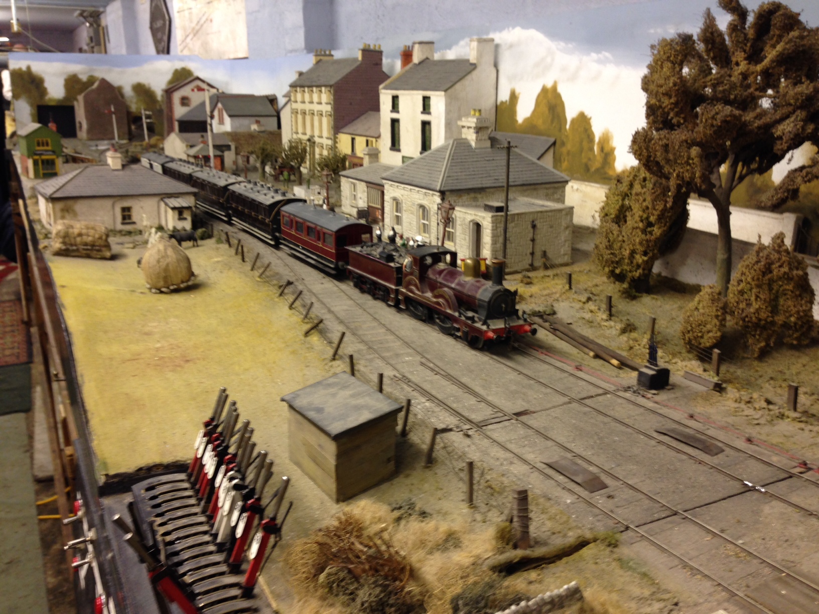
Day Return to Castle Rackrent
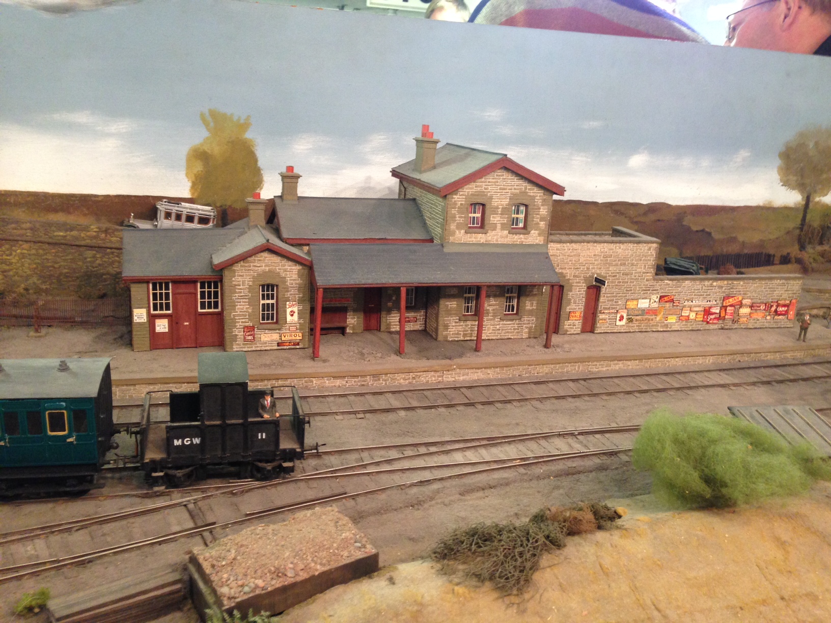
You will recall that approximately a year ago, I posted about my last visit to Castle Rackrent and I mentioned that the layout was about to undergo a significant reconfiguration. A month ago I had a chance to revisit Richard Chown and see how it is getting on.
Here are some photographs from my visit (but only a few as I had difficulties with low light levels):
Castle Rackrent Station
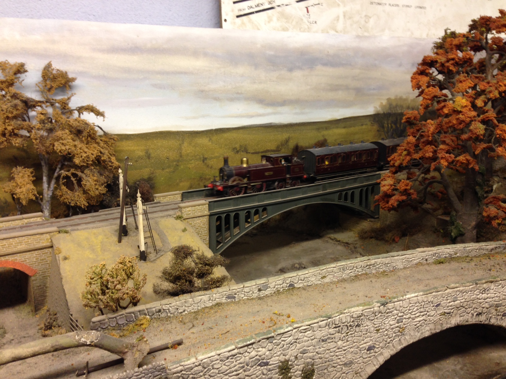
Storms above Castle Rackrent
St Juliet Town
As you can see, a number of stations are undergoing a rebuild.
A lot of work remains, as large sections of the line remain simply track on bare track on boards and some fettling of the track will also be necessary but already there is a lot done. Hopefully I will be able to visit again when things are a little more developed.
Also on view was Fangfoss which was in an even darker room, so no photos at all of the actual layout, but a few of the locos were elsewhere and here is a taster.
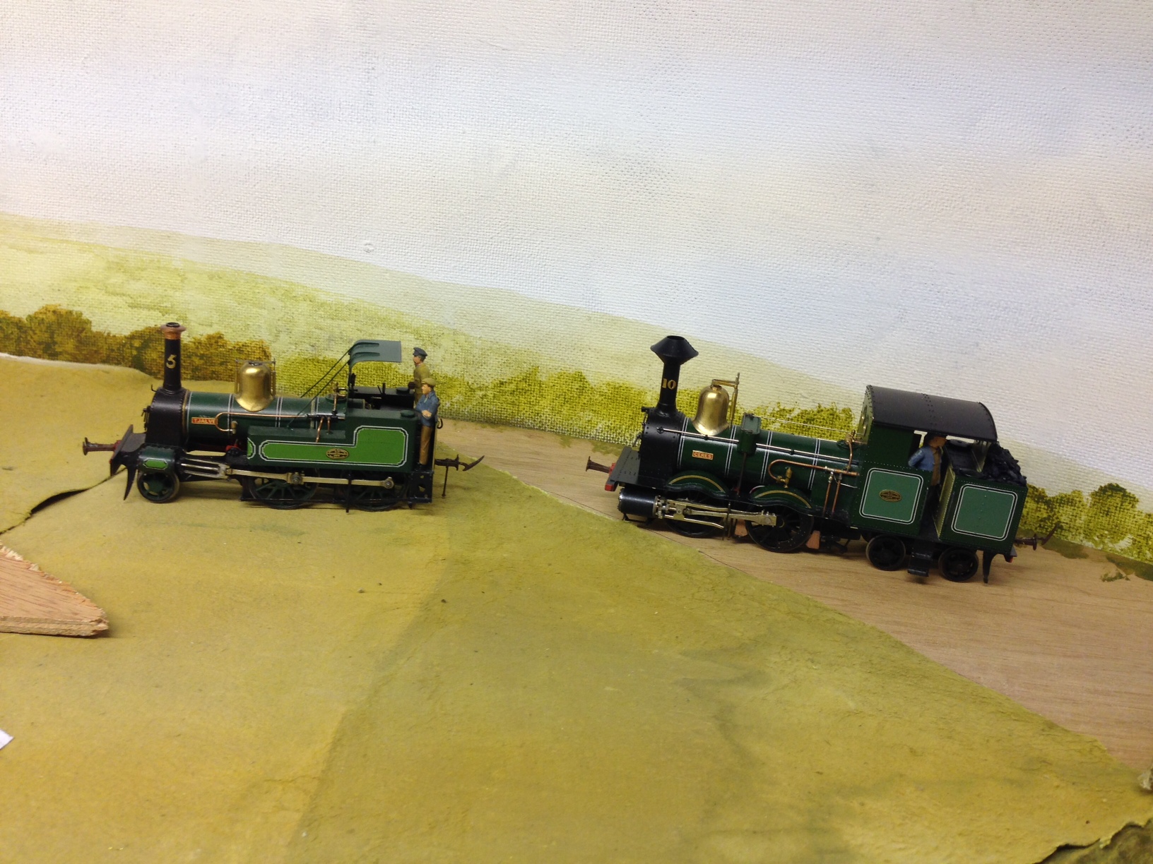
You will be able to see Fangfoss for yourself (and it is worth I can assure you) at this year’s Scaleforum which will be held in Aylesbury on 19/20 September – details here .
See you there if you go!
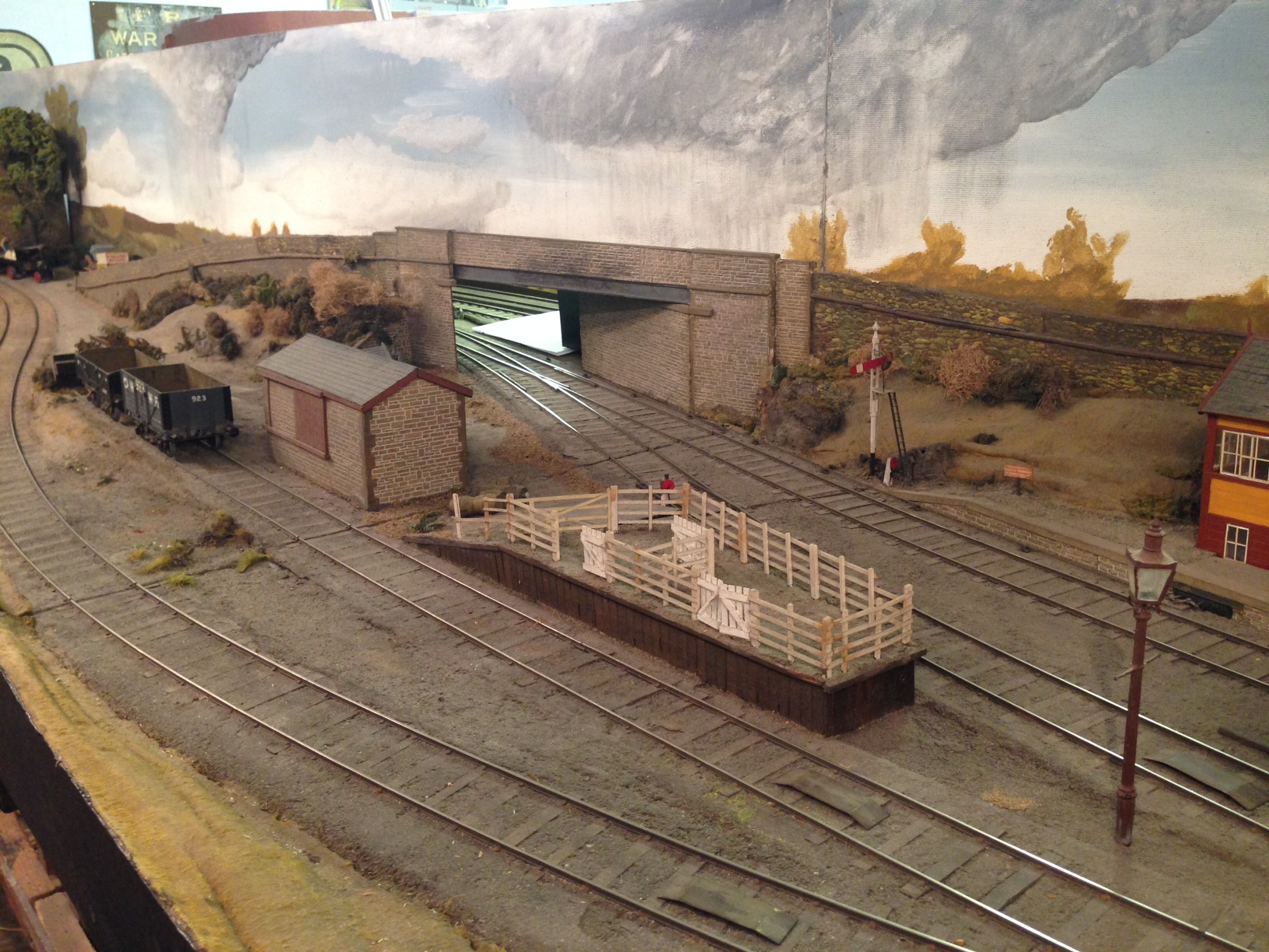
Tracklaying Commences
Definite progress was made with Glenmutchkin over the last 10 days, in that the first portions of trackwork have been laid. At last, it is an embryonic layout!
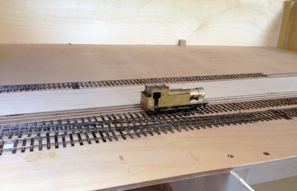
This was started at the two platform faces as in practise this is one of the major setting out points. This is because it is about the only straight bit of track on the layout and also because the platform needs to sit on top of the most substantial baseboard joint on the boards – where the front and back boards abut. The platform will be a separate element of construction and will bolt over the joint, hence hiding it from view.
The scrap tak is seen here sitting in the branch bay. The branch bay platform face is to its full length, the main line platform face still needs to continue for 500mm – into the trainshed which presently can only be imagined!
Now that the first few bits of track have been laid, a sense of scale starts to become apparent. Not for me the “model to the railway boundary only” approach – I am very definitely attempting to portray the railway in its setting.
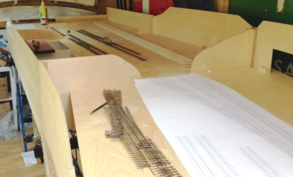
The other major setting out point for the layout is the link into the engine shed; which is a single slip from the main line and a cross-over from the main run-around loop. The baseboard joint is mid-way through the crossover, so deines this end of the layout.

Boards Back Home
Just prior to Portchullin’s last two exhibitions, Tim of S&T Joinery brought around the last couple of boards so that all of the scenic boards are now back at home. Obviously, this meant that we had to do a test erection!
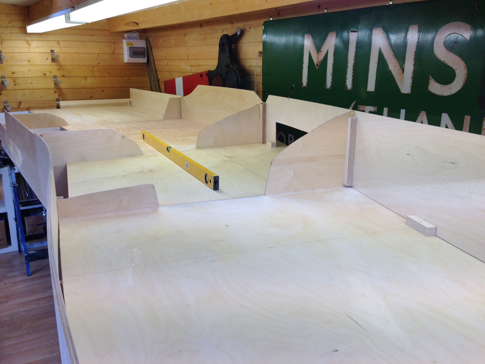
And very pleased I am too, especially with how flat they are. A rear contrast to the rolling hills affect that I managed on Portchullin. I am obviously hoping that this is going to result in much better and more reliable running.
The design of the leg and the supporting beams can now be seen more clearly. it does take a bit of time to get these level (caused I believe by the absence of levelness in S&T’s workshops! However, once the beams were level, it was a matter of moments to place the boards on them and connect them up. So I think we will do some setting out at the weekend.
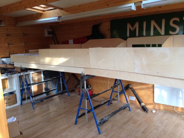
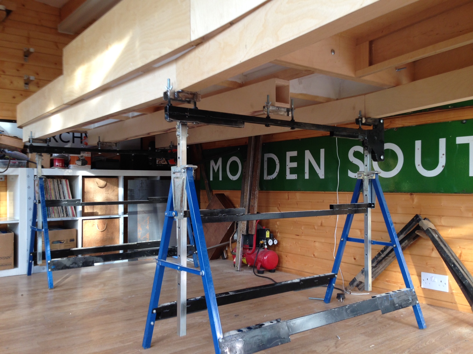
In some respects the photos don’t quite do justice to these boards and also how large they are collectively. The width in the top view is 1200mm and overall the length of the boards together is 5250mm. As will become apparent in future posts, I am going for the “railway in the landscape” feel and I don’t want it to fee cramped either.
And if anybody wants an electric loft ladder, this is where you go http://www.st-joinery.co.uk/
Scrap Tank Test Build – Part 6; Boiler and Running Plate
Now that the much of the bulk of the above running plate work has been completed, the running plate valences can be fitted. As these are nearly always long and thin, they are prone to distortion in the kits I have built – so it is time for another jig!! This one holds the valences at numerous places to stop it flexing and to hold it straight.
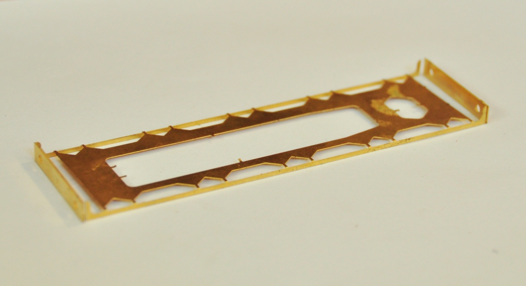
With this, it is a doddle to fit the valences in their correct place and solder them without distortion. I did find that the running plate flexed significantly at the end of the tanks; so the final version is going to include a pair of temporary stiffeners that fold down and stop this. This would be the moment when they are removed to allow the valancing to take their place.
And onto the boiler. In a departure from normal practise, I am not including a flat etch to be rolled into a boiler – it is relatively difficult to get even a pre-rolled boiler into a neat tube without a visible seam and if you do not have a rolling machine it is effectively impossible to do so. In addition, where boilers have been half etched to create boiler bands I find that the half etched elements that remain are overly delicate. This was something that caught me out a while back when I drilled such and area to take handrail knobs and badly distorted the metal – this kit is still sitting in its box now and I am probably going to have to replace the boiler.
With these problems in mind, I simply used a piece of brass tube from Eileens; easier and much more durable and if I were sratch-building I would not even think of taking a different route. This did still leave the need for some rolled parts, to make the smokebox and I have sought to use another little trick here to make these easier to fit – some tags and eyes. The tags are strips of half etching that pass through the eyes and then tugged back. This can’t impart a curve into the metal but does allow the parts to be pulled tight and makes it easier to solder into place without much of lip. Mind you, they were a tad short and will be lengthened slightly in the production run.
A second additional laminate is then needed to form the outside of the smokebox and down onto the saddle.
I did find another little error when it came to the front of the smokebox. Whilst the diameter for the front that I had drawn had allowed for the thickness of the two laminates, when you fit these there is also a layer of solder between them and whilst this ought not be that thick, it was just enough to make the fronts too small. In the production run, I will deliberately make this a tad too big as it is easy enough to file it back but much more difficult to add the missing metal (I didn’t, I just made a fresh one from sheet metal). The smokebox door is not mine, the door from the Lochgorm Models Loch is the right size judging by the photographs (note the drawing in the old man’s book has it being smaller but this does not match the photos, so I ignored it in this respect – sorry Dad!).
The downside of using tube as a boiler is that boiler bands need to be considered. I have provided these in the kit (again using the strap and eye technique). I chose to fit them on this kit although in practise I think any metal boiler band is too thick and would probably have done it with a transfer sheet if this was not a test build (done prior to painting, the thickness of the transfer is enough to show through the paint on what will be a single colour to the boiler).
Only the top of the boiler is visible after the first ring and a bit, so can be cut away to leave lots of room for the motor, weighting and DCC chip. I may try and fit this with sound, so who can give a view on what it might have sounded like – a jinty is my favoured guess?

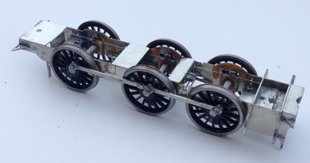
Scrap Tank Test Build 5 – Getting on with the Chassis
With the basic chassis made, it is essential to fit the nuts to secure the body to the chassis as both of these will be concealed with later work. So a quick test fit looks like this and we can get onto the next bit, the coupling rods. 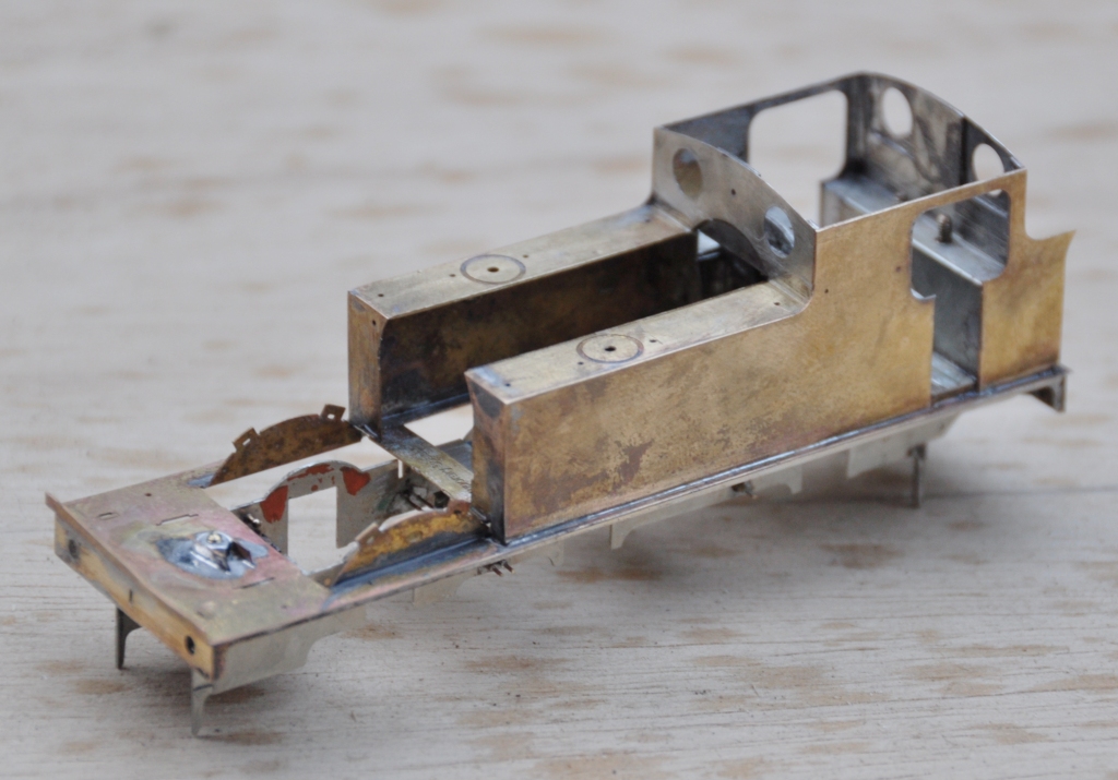
As is not uncommon, these are made from a pair of layers of brass laminated together. You can see that the outer layer is half etched for much of its length, with the full depth only being present at the bosses. I have also sought to make it easier to build these by including them in a folding jig – the folding is underway in the bottom portion of the view. The logic of the jig, indeed the whole kit, is to make a really smoothly running chassis much easier to make. Modern CAD and computer operated phototool creation techniques by the etchers means that it is possible to easily draw and then etch such that each dimension is faithfully repeated on the product. Thus, it is possible to be confident that the wheelbase will be repeated exactly on each side of the frames and also on the coupling rods. However, this accuracy is completely lost if the user has to laminate the two parts together by hand; it is not possible to get them superimposed on each other exactly or repetitively so the spacings of the crankpin holes will change. The jig overcomes this as the fold line is so long that there can not be any twist as it folds, so the two parts will meet consistently and accurately. 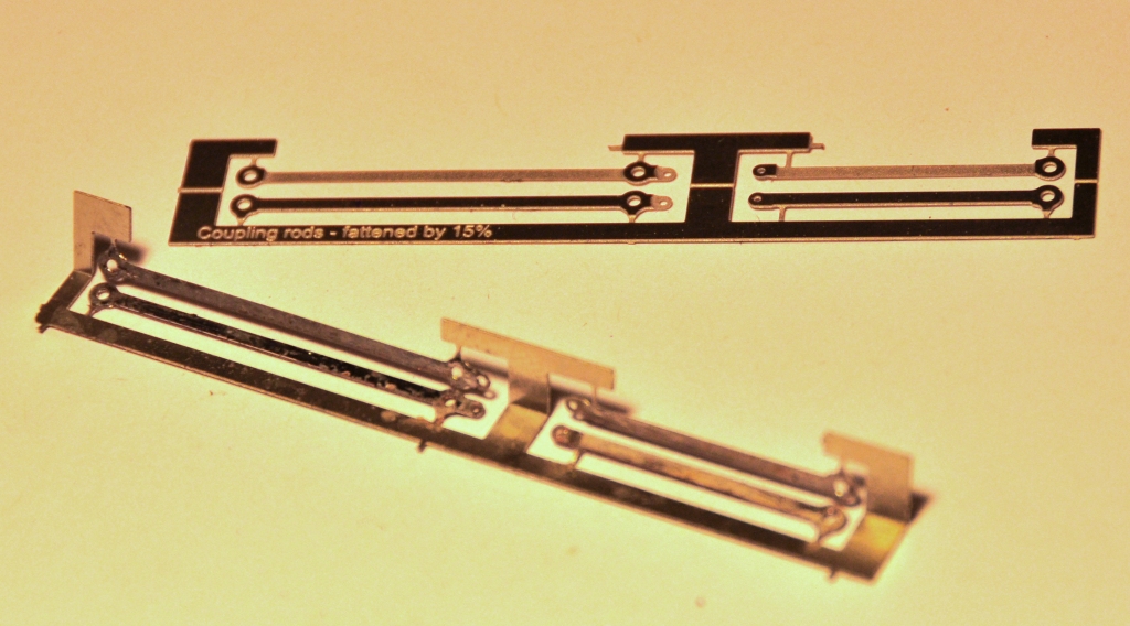
It is true that there remain two areas of variability. The first is that the degree of etching will not be exact on every occasion so the holes will be slightly bigger or smaller on each occasion. This can be easily overcome by making all critical holes a tiny bit too small and then opening the holes up with a ream (not a file, reams will open up a hole consistently). The second problem is that a fold is not always consistent on a fold line so the jig can protect against twisting but might not necessarily put the two laminates directly on top of each other. However, the important point is is that they will be correct horizontally, any error can only crop up vertically. Thus, when the crankpin whole is opened up, it is possible that it will move vertically slightly but this will not change the dimension between the holes so the critical dimensions should be retained perfectly.
The above is all true in theory but in practise there was an almighty cock up in my artwork; so I was deprived of finding out. A total case of designer error and when this is yourself, there is no one else to blame………………. 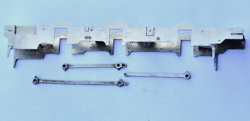
………..I made one of the coupling rods no less than 8mm too long – doh! I have no idea how, but it needed chopping; so it was back to the old fashioned way of making coupling rods despite my high ideals! Fortunately, as they were laminated, it is possible to stagger the cut to make the splice – essentially the same technique as Alan Gibson’s variable length coupling rods. Anyway, after the cutting and splicing, I did get a sweetly running chassis and this is what it looks like. The unusually large wheels for a shunting loco are already making their presence felt! 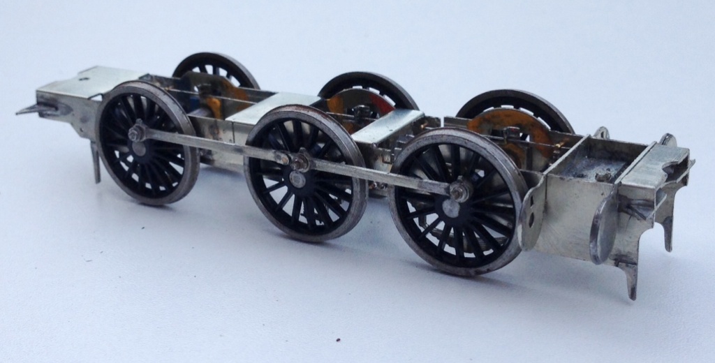
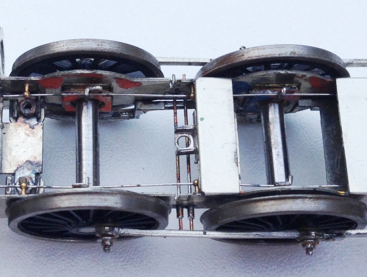
The chassis is created around CSB’s; continuous springy beams. A spring wire is anchored to the chassis at four points per side (for an 0-6-0) and at the centre of each hornblock. Thus each hornblock is supported on either side and can “bounce” on the spring. However, the clever thing about CSBs is that when a hornblock is depressed, not only does the spring wire flex a bit as suspension, but it also rocks on the anchors so the adjacent wheels push downwards a bit to equalise out some of the deflection. It produces a really smooth chassis and, if it is conceived at the design stage, I think is actually rather easier to both design and build than traditional compensation. This is a close up of a pair of hornblocks and a pair of the anchor points (the other is hiding behind the frame spacer on the right). Also worthy of note is the colour coding of the hornblocks; to enable them to be reinstated in the same hornguide each time. This is probably unnecessary with modern (and therefore consistent) hornblocks and the accuracy of the etching I have noted but old habits die hard!