Blog Archives

At last, a Finished Signal!
Well, that took a while longer to make than I had hoped! Not least because it is not the only signal I am working on at the moment.
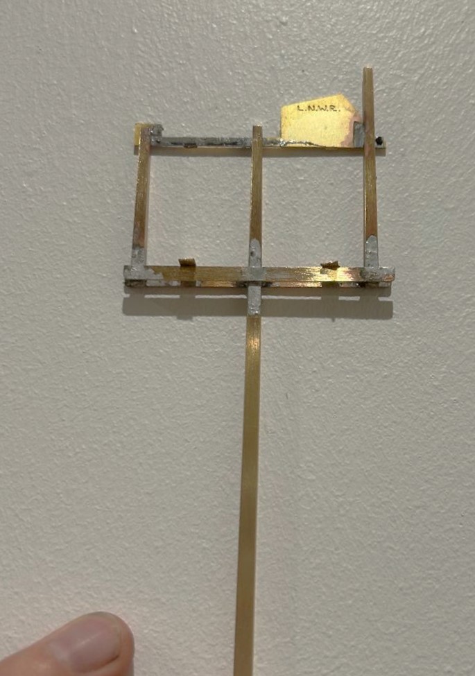
Although the drawing did not show a landing in front of the balance weights, i felt that it was likely one would be provided given that these need maintenance at times. Hence this was formed from some L section and an etched slats and provides a useful point to secure the ladder too.
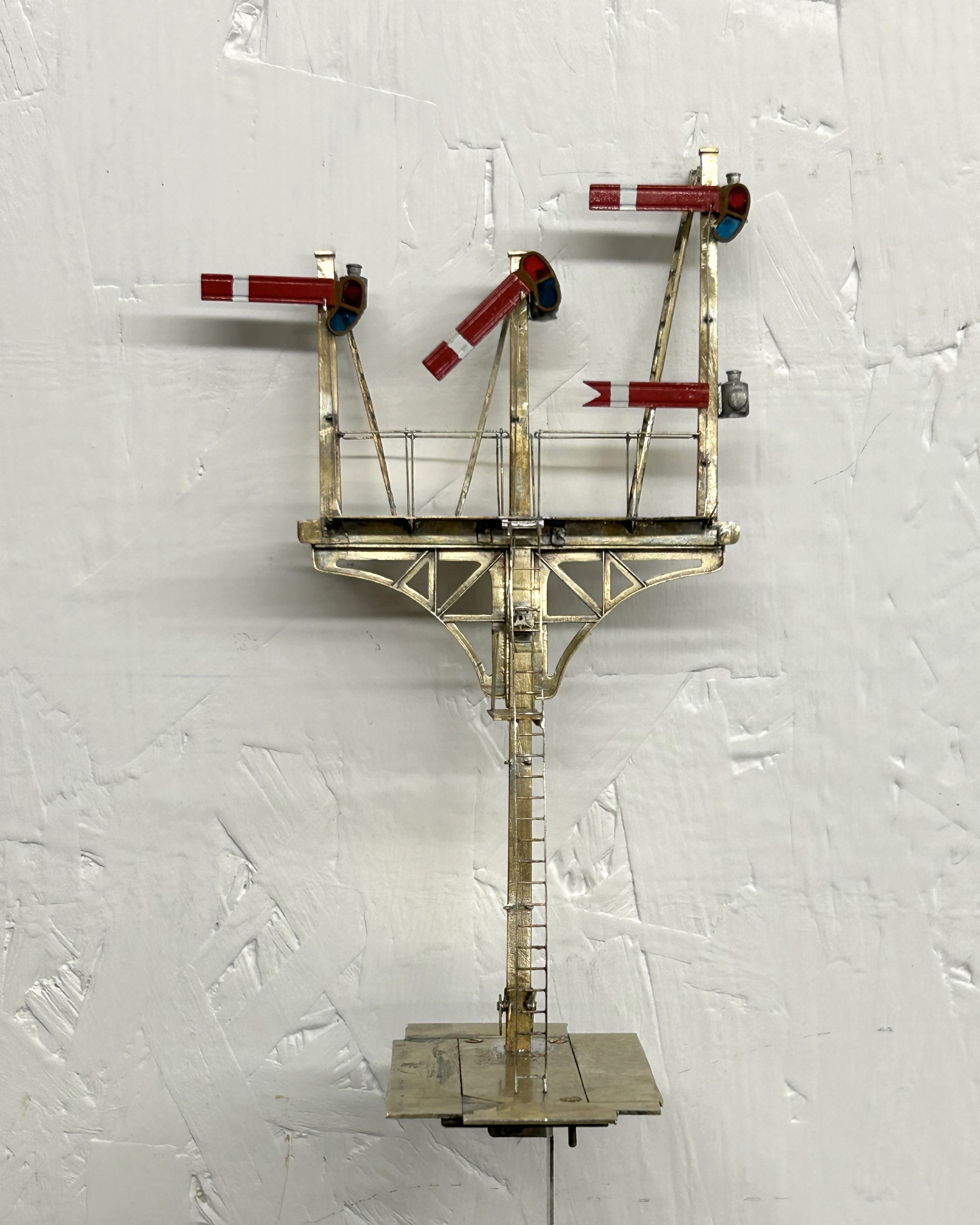
The issue with signals with dolls is that each doll is in effect its own signal; it has a ladder, arm and lamp assembly. But worse than this is that it is also necessary to get the movement to transfer over to the doll so there is even more than a seperate signal per doll. There are a number of ways the prototype used to get the movement to transfer and in this case the signal uses L shaped elbows. Sadly these are more challenging to make as there are more working components and to be prototypical they out to be little more than a couple of mm in size.
A key trick in making signals is to spray paint as much of the signal as possible. Because the components are generally fine any excess thickness of paint will quickly make the modelling crude. As a result of this, I now generally try to make the ladders detachable. In this case there is a rod attached to the top of the doll that a tube at the top of the ladder slips over, with prongs at the base.
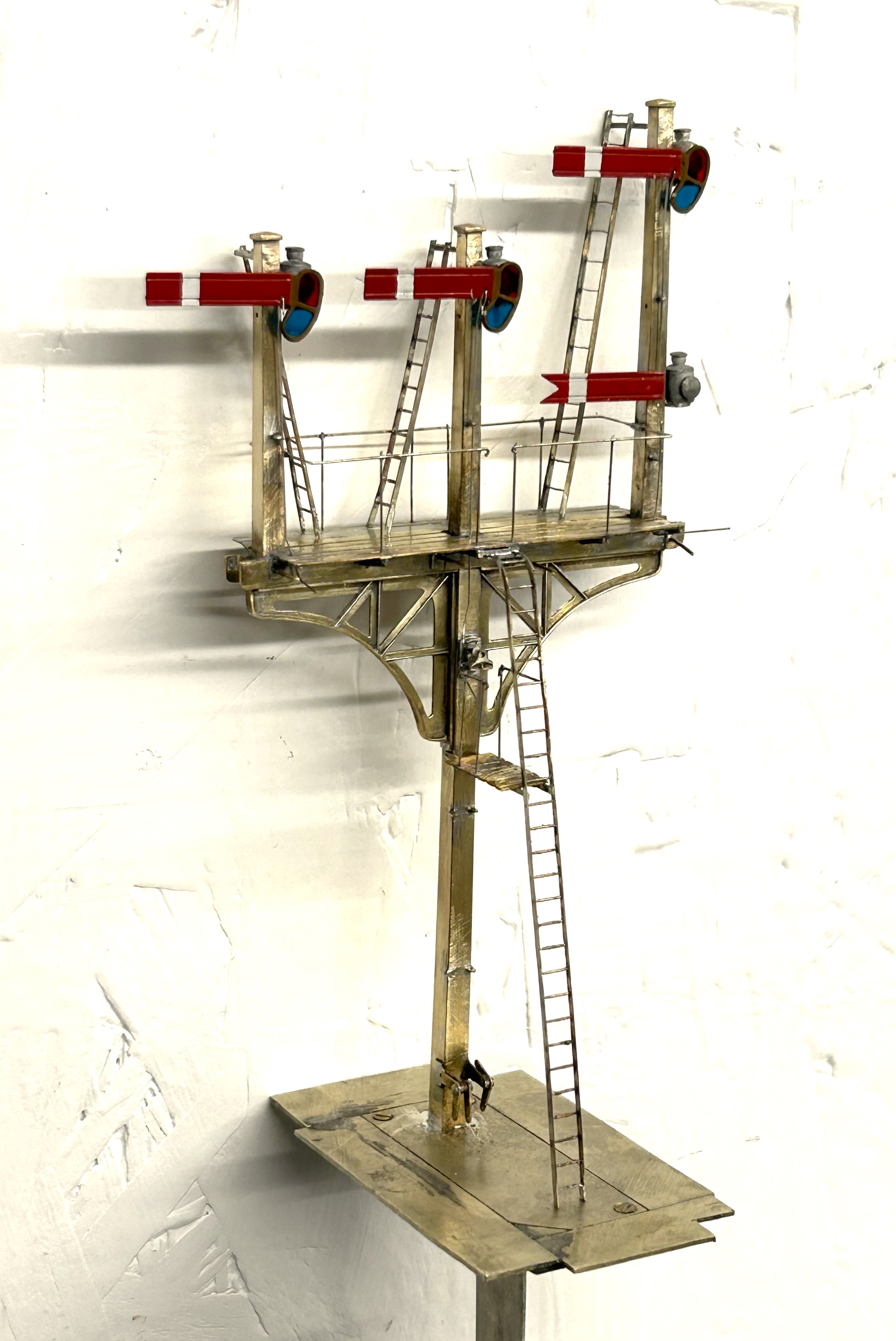
So here it is a finished (except for a tie rod which I fortgot to paint so is to be fitted shortly).
And as is de rigeur for a blog post on the building of signals, here is a video of it in operation.
")
More Seasons Greetings (and Signals)
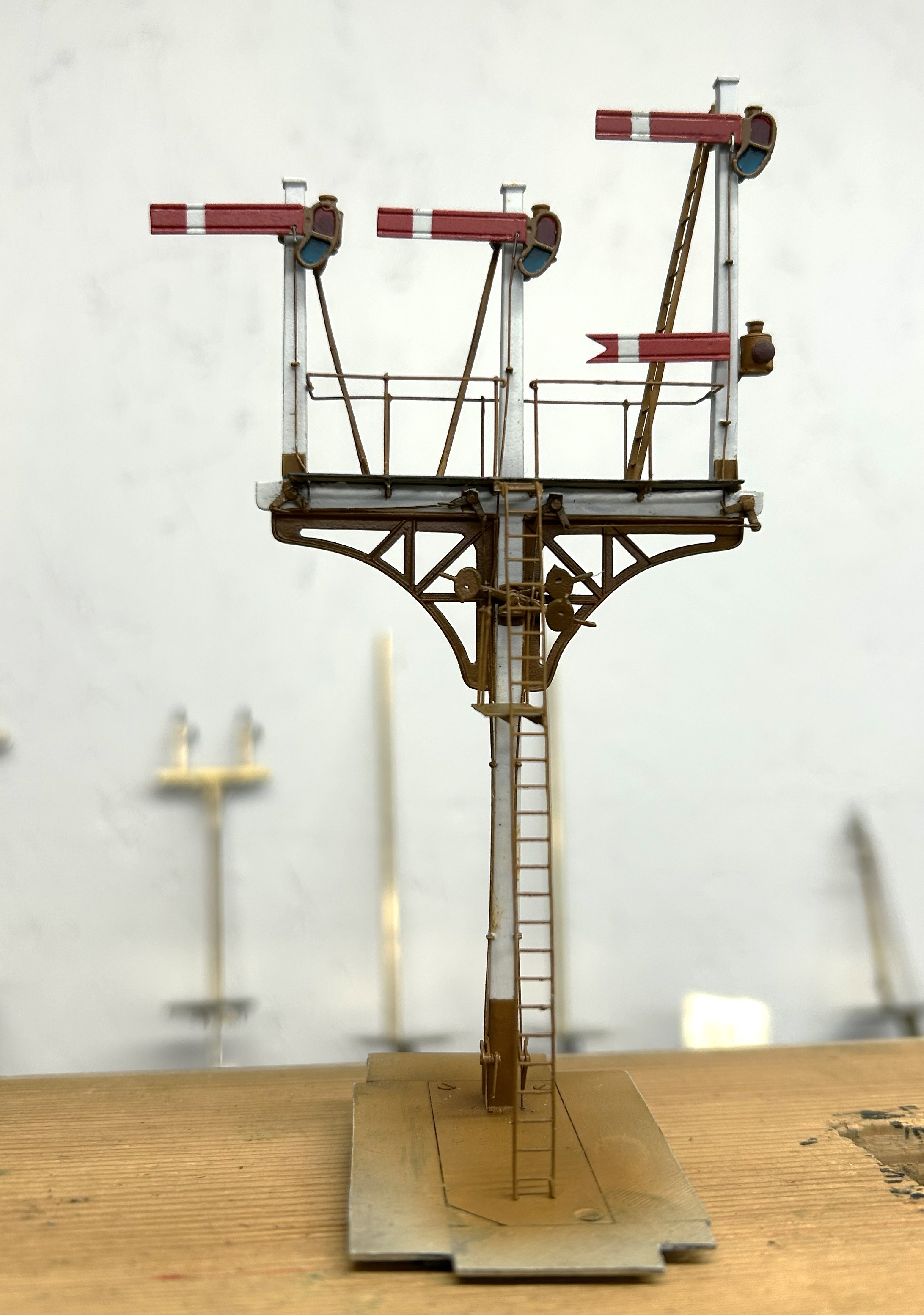
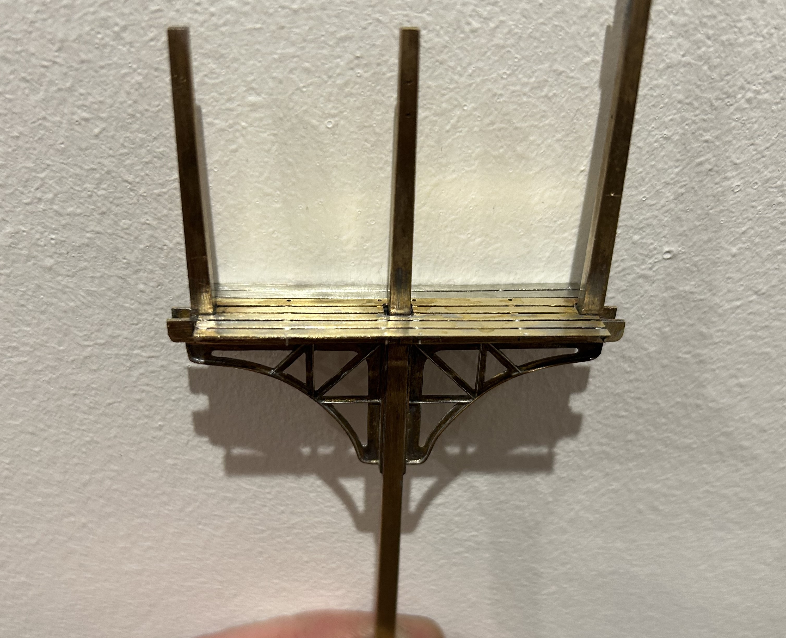
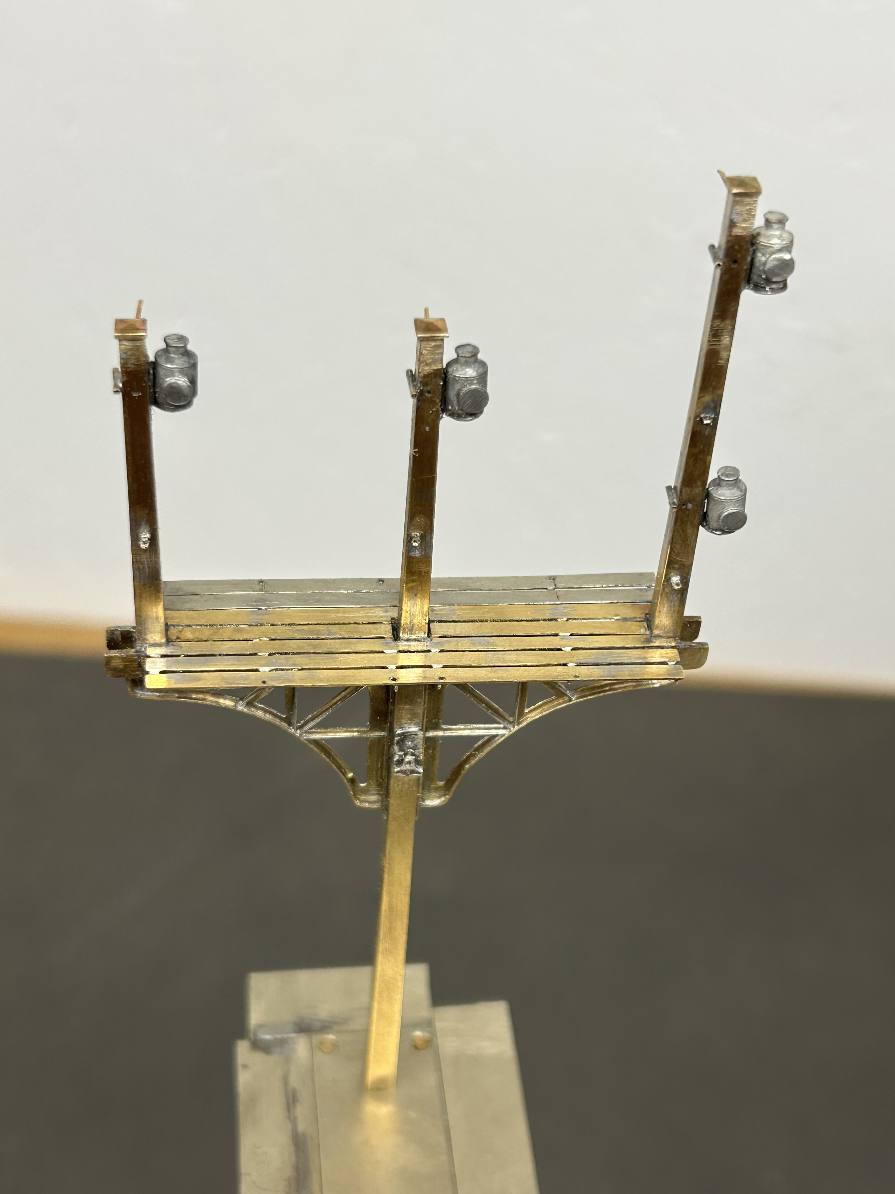
Having got the post and dolls in place, the next step was to fit the brackets.
The LNWR were unusual in not using cast brackets; instead they fabricated theirs from sheet and angle iron. Those supplied by MSE are a flat etch and therefore feel a bit one dimensional.
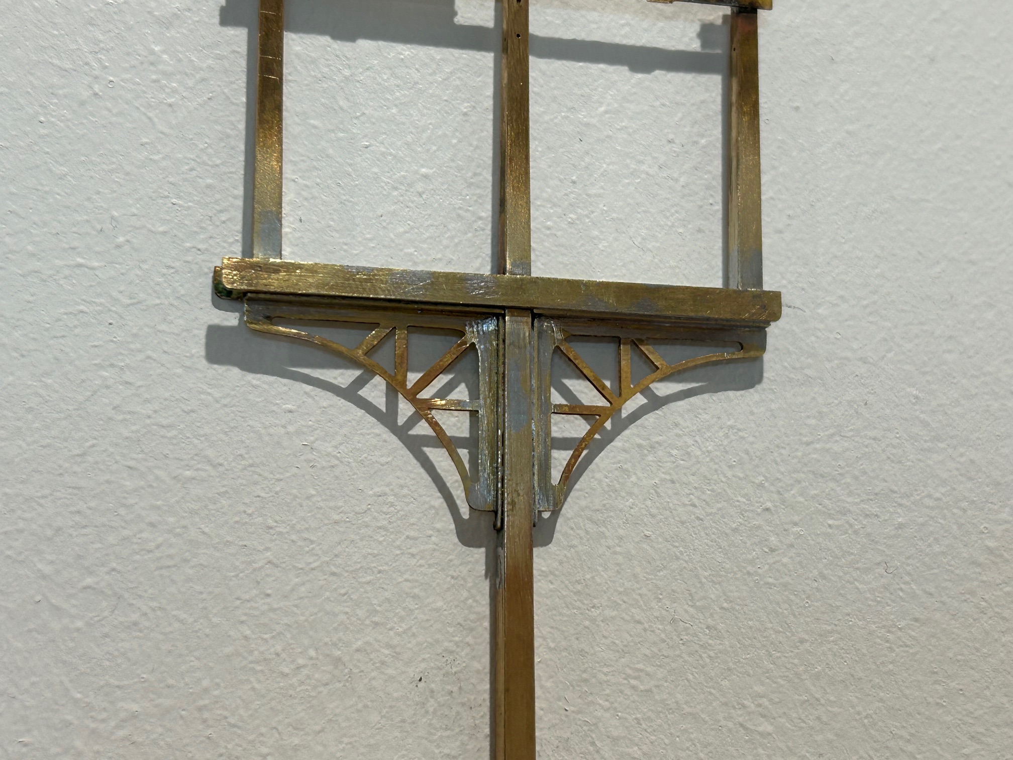
I therefore sweated on brass wire to one side of the strutts on both faces and also a plate on its outer edge. This helps give this a third dimension that was lacking before.

The next issue to be confronted was the landing where the MSE etch only provides a landing to the rear of the posts whereas this (and it appears many other LNWR signals) have landings both sides. I therefore had to produce support brackets and an enlarged area of landing. Foolishly, I forgot to drill holes for the guard rails before assembly, which meant that i had drill them in-situ. This is awkward due to the proximity of the dolls – it cost a couple of drill bits as a result and as a useful reminder to get it right next time!
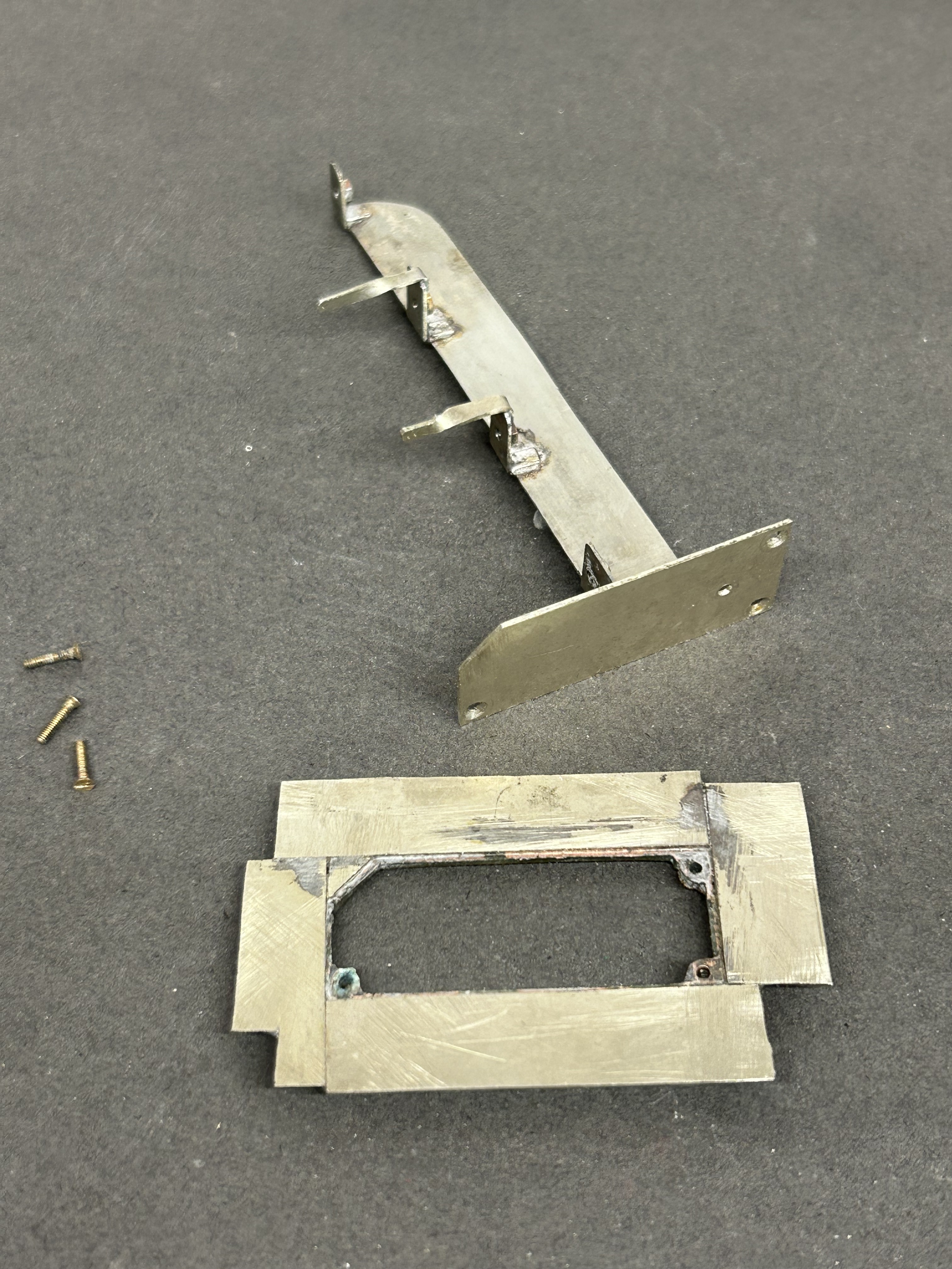
Next, I diverted my attention to the the mount for the servos. I now always form these with a lower base which is permenantly attached to the baseboard and into which a second detachable base plate is inserted. The two are a tight fit such that once a little scenary is applied to the top, the joint is invisible. These are secured together with 12BA screws to allow it to be detached both during the build and for maintenance but generally it is secured in place. This is because signals are prone to damage when being moved about and would need recommissioning to get the movement correct each time they are reinstated.
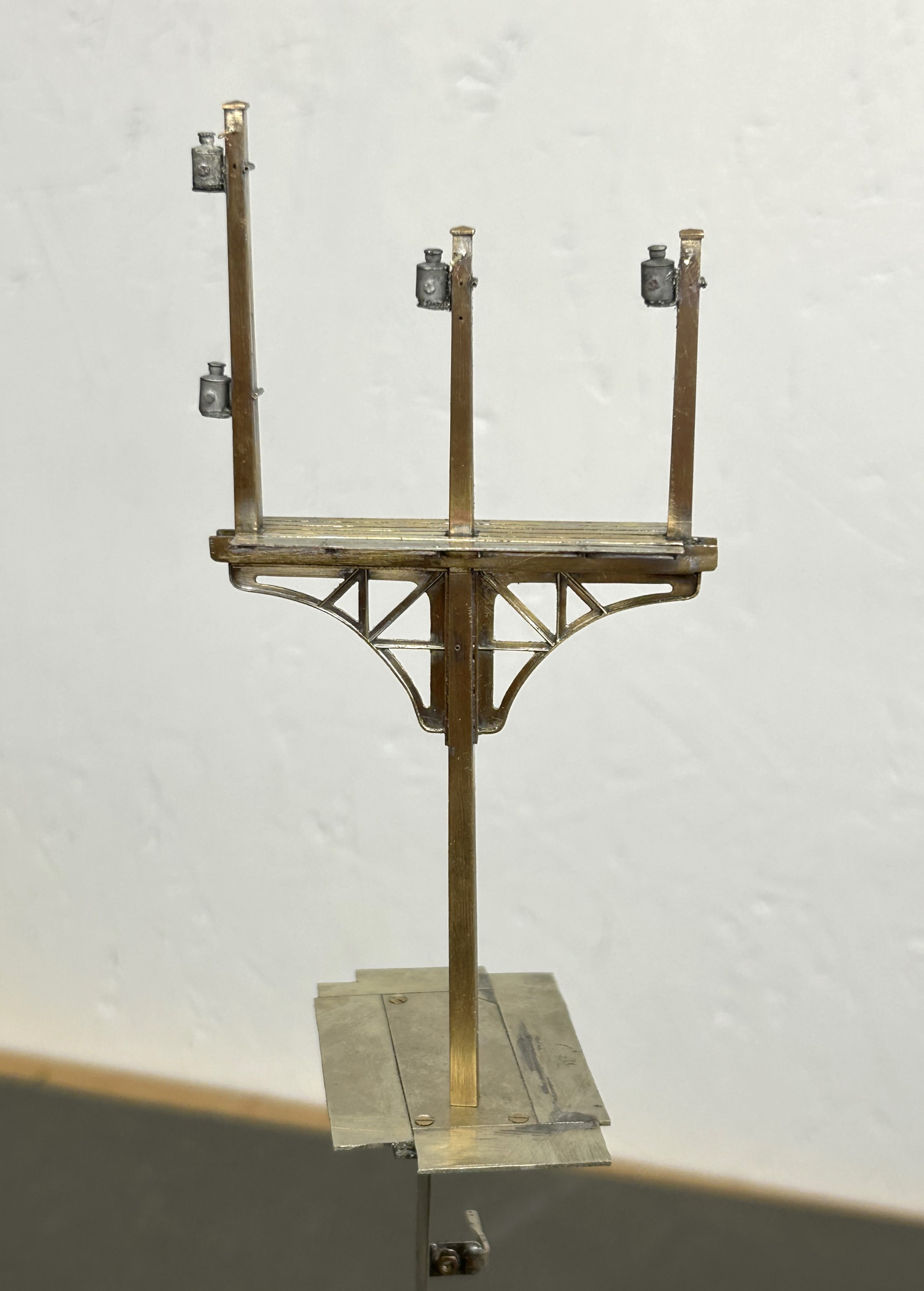
I drilled the underside of the post and tapped it 10BA in order to hold it in place. This enables me to secure it onto the base but subsequently remove it as I build it. I do solder it in place at the end of the build, but the ability to remove it during the build is helpful. The fact that the bolt holds it in place also makes it easier to get the post vertical, rather than trying to hold it vertical simultaneously with the soldering.
Whilst MSE do provide a white metal casting for the finials, I opted to fashion my own with brass as I find them crisper. To ensure these do not fall away as later tasks are completed, I use a high melting point solder for these and also include a pin drilled into the top of the post. Lamp brackets, lamps, the balance weight mount and some supports for the ladders were next.
I now have a recognisably signal beginning to form but the difficult bit, the movements are still to go.
")
Seasons Greetings (and Signals)
Work (at least real work) is now over for 2025 so I can get a bit of time in for turkey, mincepies and, of course, some signals.
I have built up a number of promises to make people signals; more than enough to keep me fully entertained for not only Christmas but quite a lot of time afterwards! It is time to start delivering on these promises.
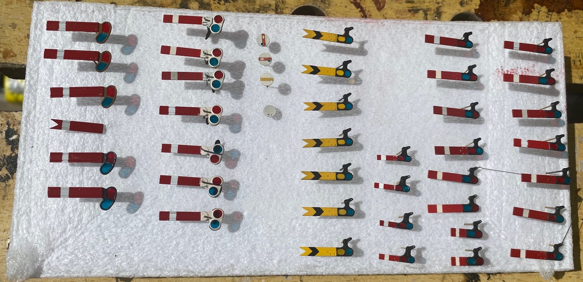
First uo has been to paint the arms. I know do these in advance as there is a lot of effort to paint them well and the best finish is by masking and spraying most of the colours. I can’t seem to brush paint to a good enough standard. I do, however, form the black shevron on the distant signals with black transfers as it is difficult to mask this neatly and the bars on the ground signals are a transfer from 51L.
I should be busy with this lot…………
In another departure, i have borrowed a milling machine to assist me in making the tapered timber posts. I form these from 4mm square brass section, a selection of files and a lot of elbow grease. It is a chunk of work for one signal but I have six taper posts and eleven taper dolls to do – I am not sure i have enough elbow grease to do this many!
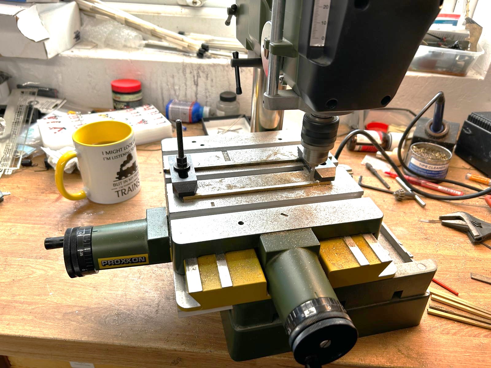
I propped one end of the post to form the correct taper with the mill travelling level. it was not without problems as the brass tended to flex (upwards oddly) where it was not supported. I ended up using the mill to take most of the weight off the metal and then went back to the files to finish the task off. It does reduce the effort, but it is still hardwork – and i have only done half of them so far!
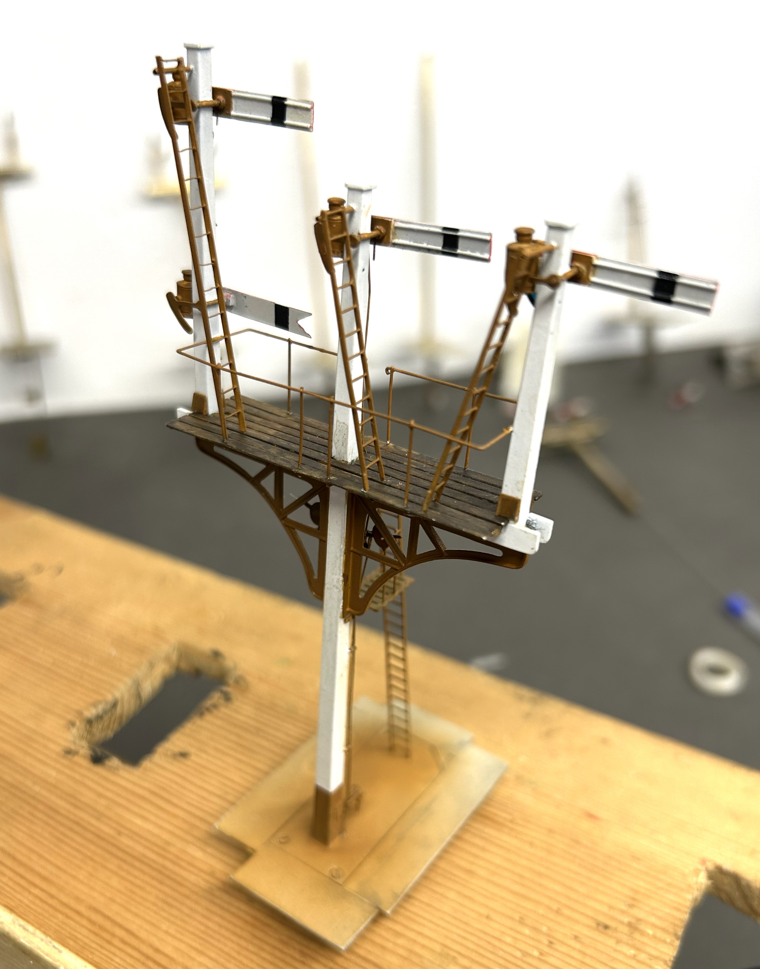
The first signal up is a LNWR three doll signal with three moving arms plus a fixed distant. Nearly as shown in this official drawing.
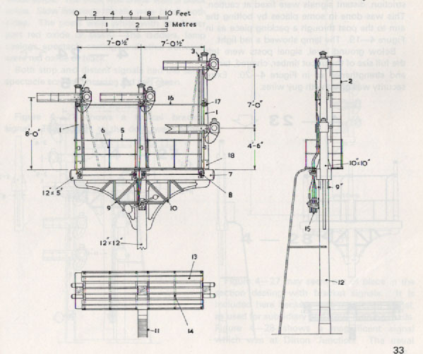
The basic posts and dolls are now in place; with various scarp etch temporary strutts to keep it square. Still a long way to go though!
So i wish you all a great Christmas and a Happy New Year.

Now That Didn’t Take Long…………..!
I have recently bought one of these – a minature bench saw by Proxxon – second hand from ebay for a moderate amount of money, along with a diamond disk with the intention of using it to cut copper clad fibre glass.
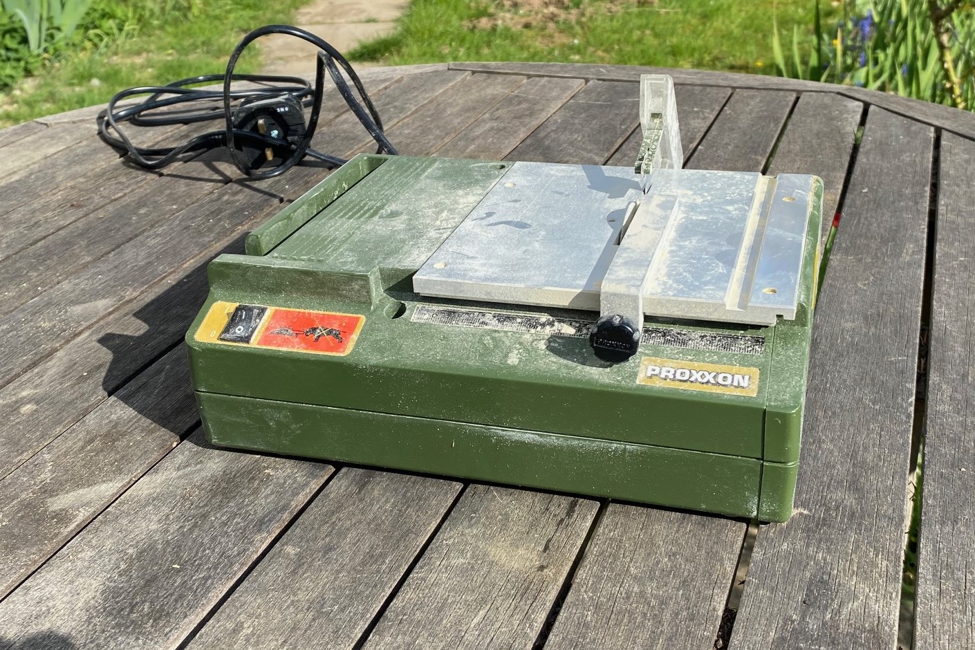
If you have attempted to cut copper clad sheet yourself you will know that it is a stunningly good way of blunting tools!
I wanted a better way of cutting copper clad sheet for frame spacers and, particularly, sleepering for trackwork. Having got it I obviously wanted to put into use…………..
So obviously I didn’t choose something simple and instead opted for a scissors crossing because I have never built one before. So here is it, a B7 turnout scissors crossing in P4 with a relatively wide line spacing as this is to be used in a fiddle yard between the up and down roads .
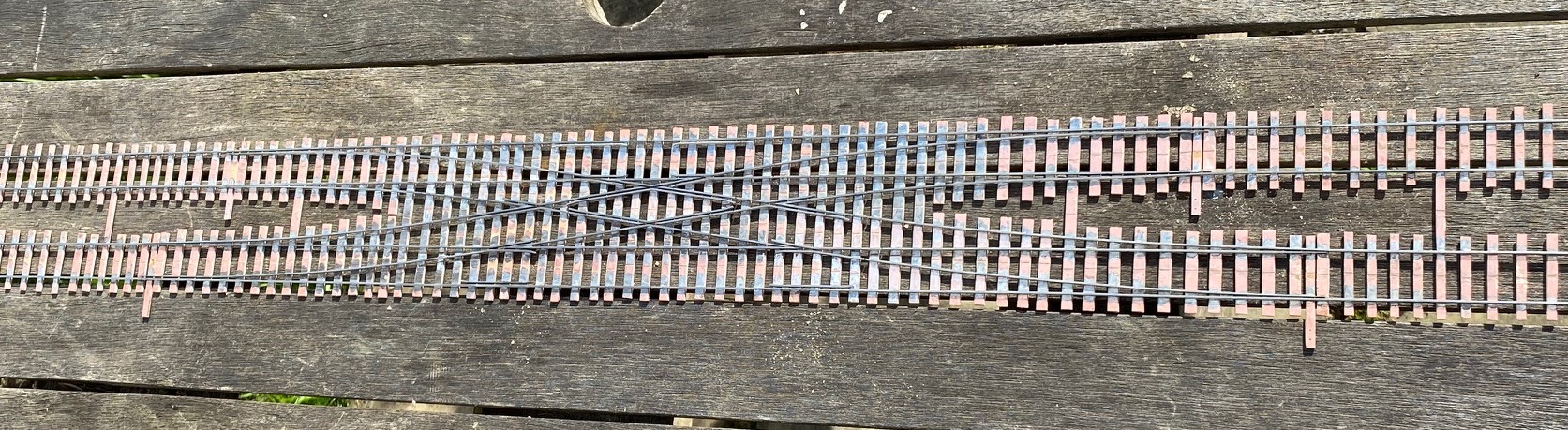
This represents over 24 hrs of work even though the time to make the sleeper bases was quite moderate.
My conclusion on the bench saw is that it is a much better way of cutting through copper clad sheet. The diamond blade slices through it easily. What is less good is that for fairly narrow strips (such as sleepers) it is difficult to get a consistant width along the strip even using a fence. Not a problem for fiddle yard track, but if it is to be used out on the front, it will need to be better.
I have also spent some time thinking through how i can wire this as it is quite challenging for the crossings for the central section. After much pondering, i have decided it is not challenging at all as i will simply cheat and use frog juicers !

What Have I Been Doing…………..?
Gosh, another year where my intentions to increase my rate of posting have got away………..
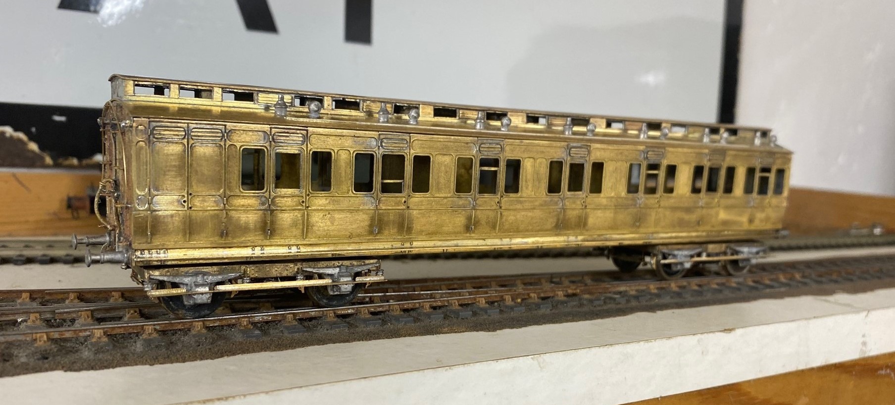
Whilst work and home life have intruded, I have still managed to get some modelling done; including a rake of NER coaches for John James for which i do get something in return in due course.
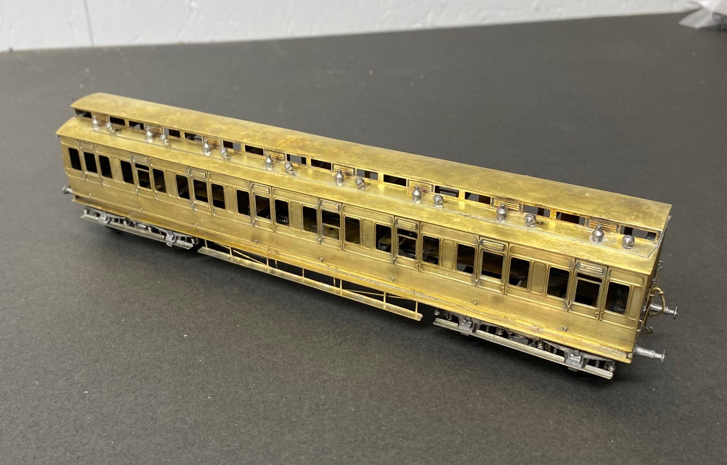
The rake had a pair of three compartment thirds, of which this is an example:
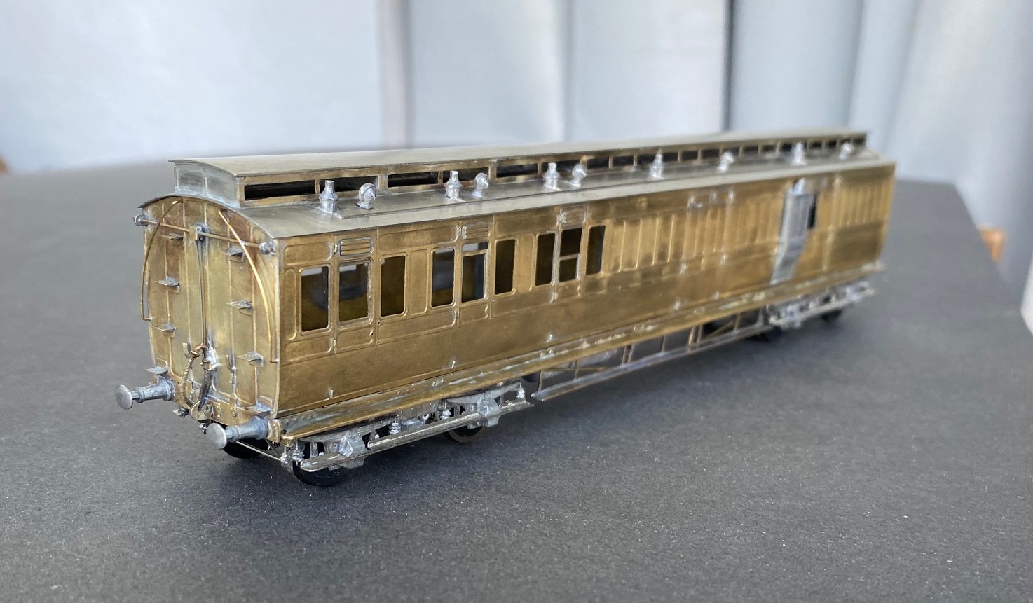
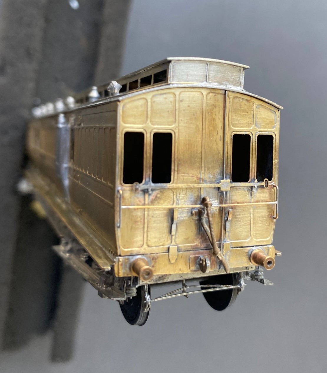
All of the coaches were constructed from D&S kits on my Miscellany Models Fox bogies with replacement roofs formed of nickle silver sheet. I find that the plasticard offering in the D&S kits to be their weakest point. The problem with this is that if you make your own roofs i find you might as well also cut out the section below the clerestory – it makes a huge difference for the coach to be illuminated from above. The issue is, that there is a lot of work in these roofs – I found that for each there was 15+ hours of work just in the roof!
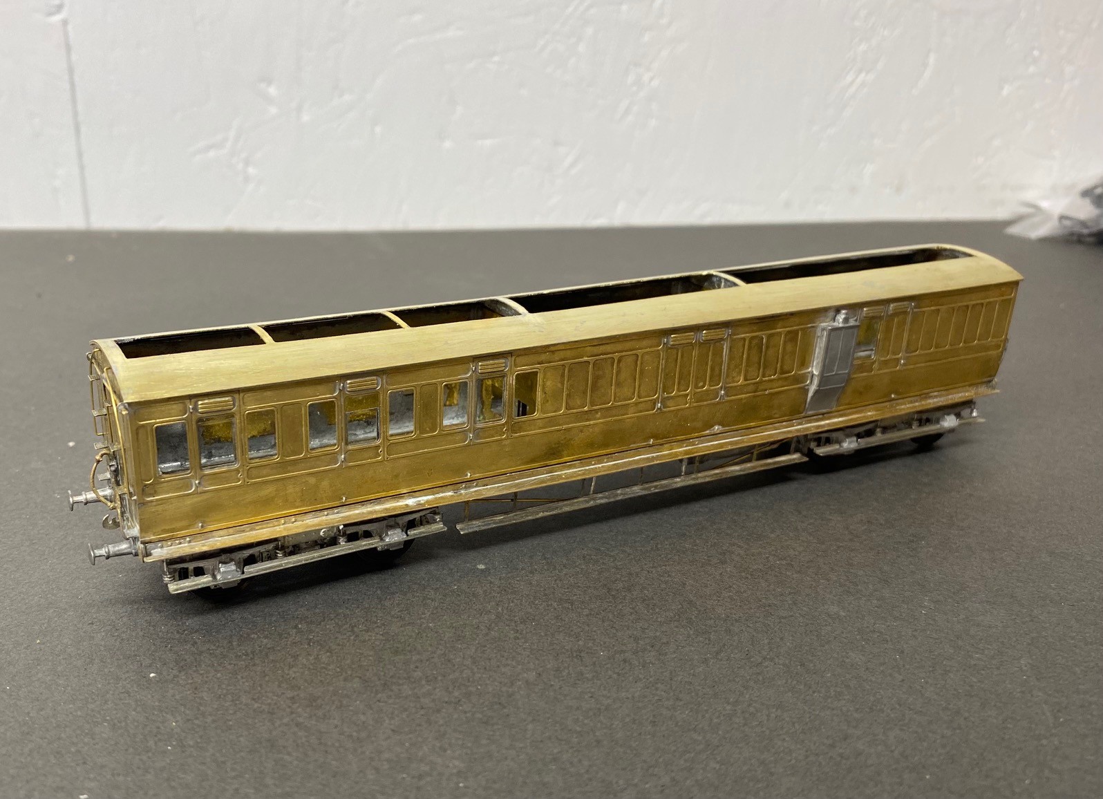
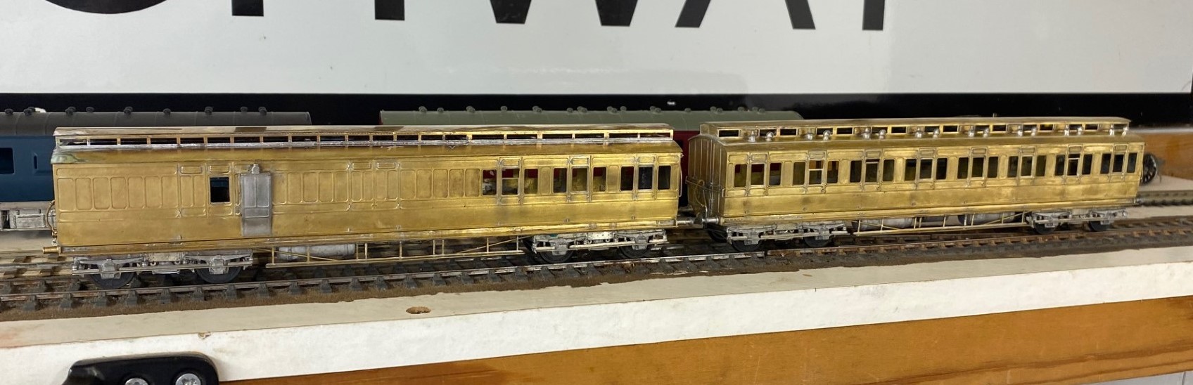
Also in the rake is an all third, which is probably my favourite of the build as it feels quite “pure” and also wihtout the problems of the composite…….see below…….
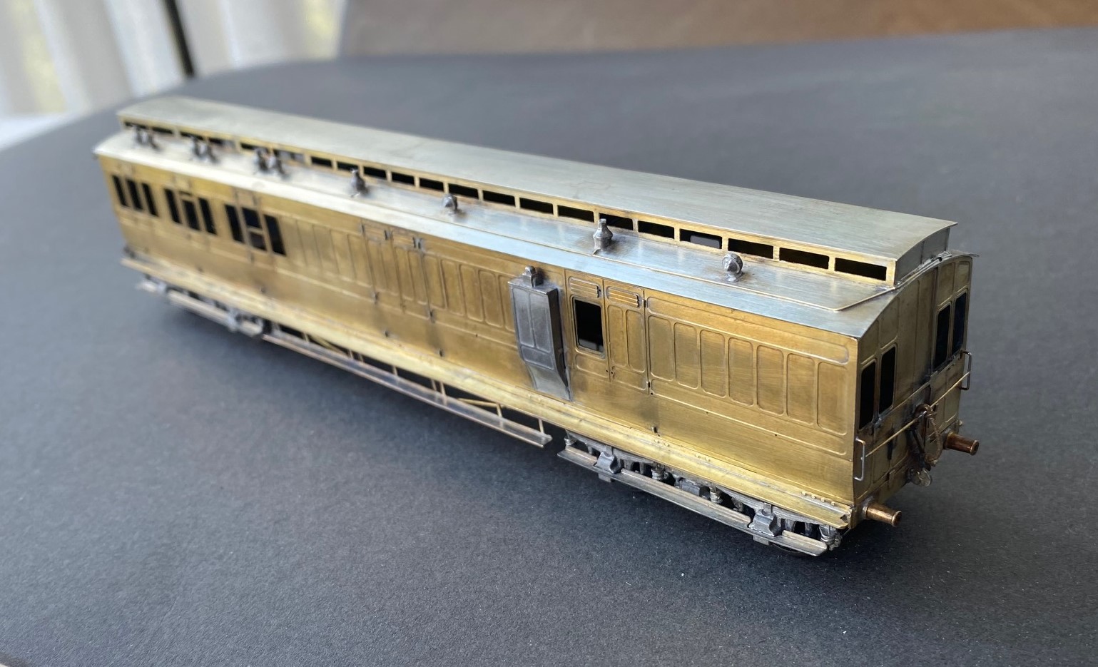
The rake only needed a modicum of first class accomodation made up from a composite diagram 7. Alas, this had a challenging problem that needed to be overcome, with the clerestory side pieces. These were much shallower than those on the other kits orwith the ends supplied in this kit. In addition to being obviously incorrect given the inconsistancy but the frames around the glazed lights were stunningly delicate. I regret persisting with this, i should have just drawn up some replacements in CAD and popped them in the next etching order.
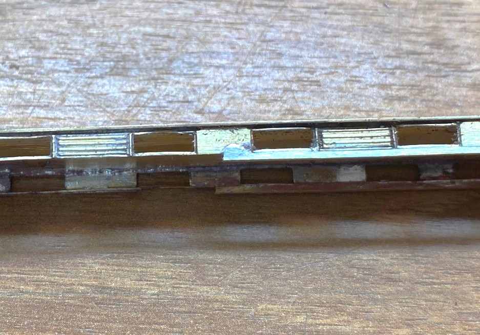
However, i solved the problem by soldering a flat strip, 1.5*0.5mm along the base. in theory it should be to both the top and bottom but that was not realistically possible and I decided life was too short. After much fighting, cussing, fighting, screaming and more fighting, I did get it there, as I hope you can see.
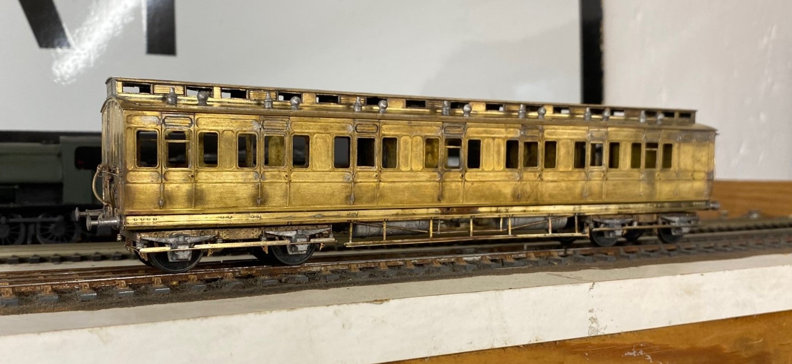
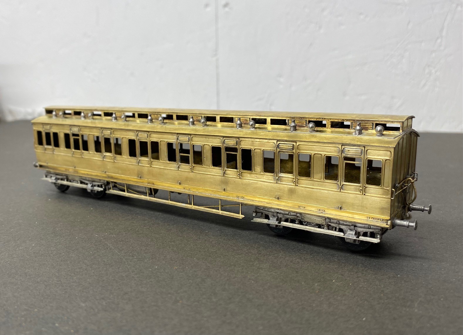
I was asked to do these as gas lit coaches and therefore there is a bit going on below, as one might say.
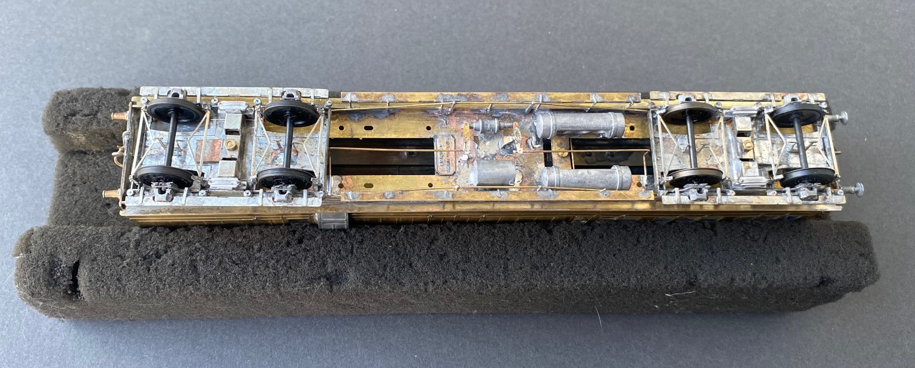
As the coaches were quite long lived, they went through many detailed changes. for anyoen who is contemplating building some, I would heartily recommend reading David Addyman’s notes on how he built his in the Scaleforu Forum https://www.scalefour.org/forum/viewtopic.php?f=39&t=7210&p=101662&hilit=ner+coaches#p101662 David’s coaches are modelled in the 1930s, so have different lighting arrangements, footsteps, bogie spring dampers and sides to the clerestories. Lots of things to be aware of if you are doing something similar.
At the end of this rather mammoth build, I had four coaches that i was rather proud of. They look rather fine on John Wright’s Benfieldside viaduct.
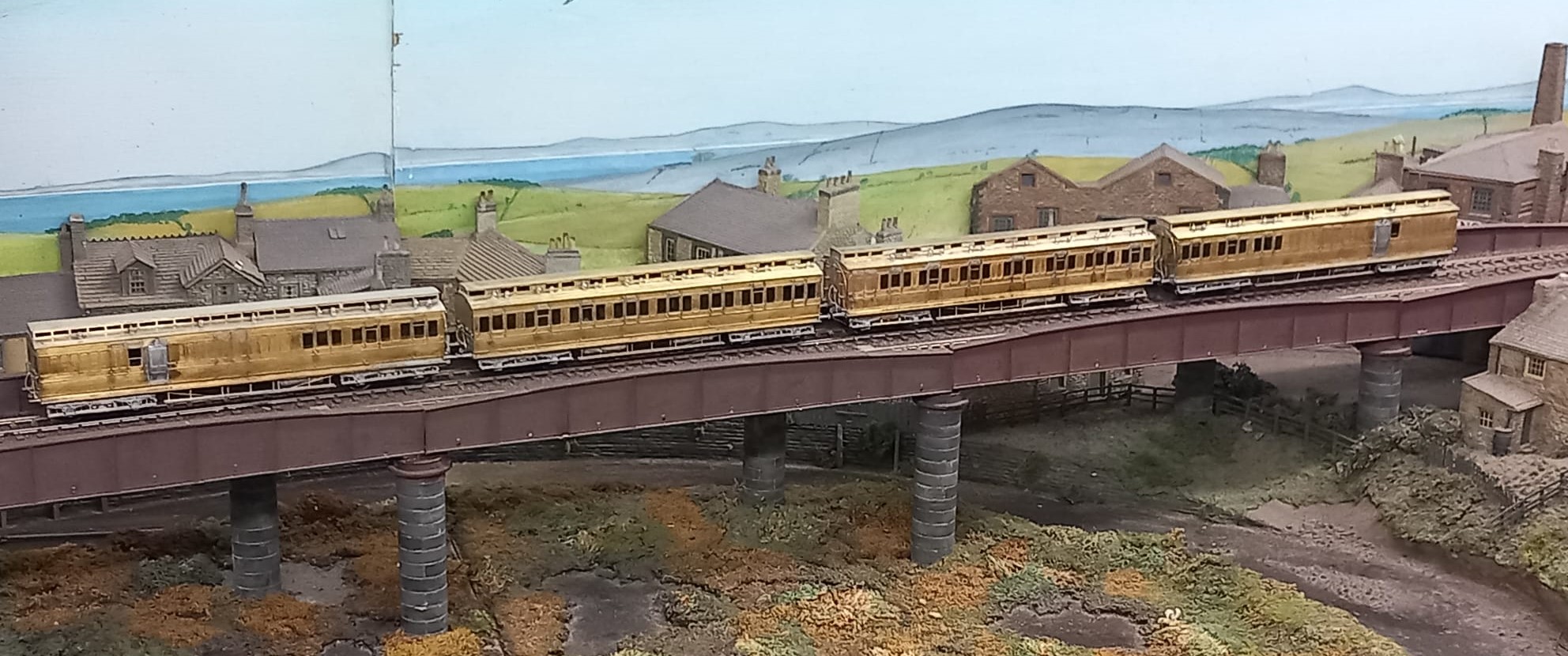
I am also pleased that i do not have to paint these; i am still looking for my lining mojo. I had it as a teenager, but have grown shy of lining. Maybe something for the Christmas break?
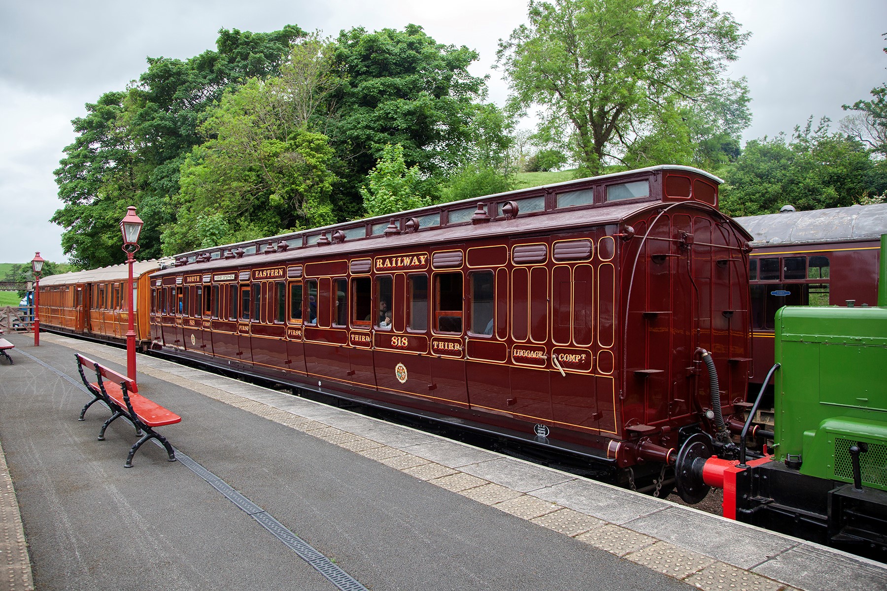
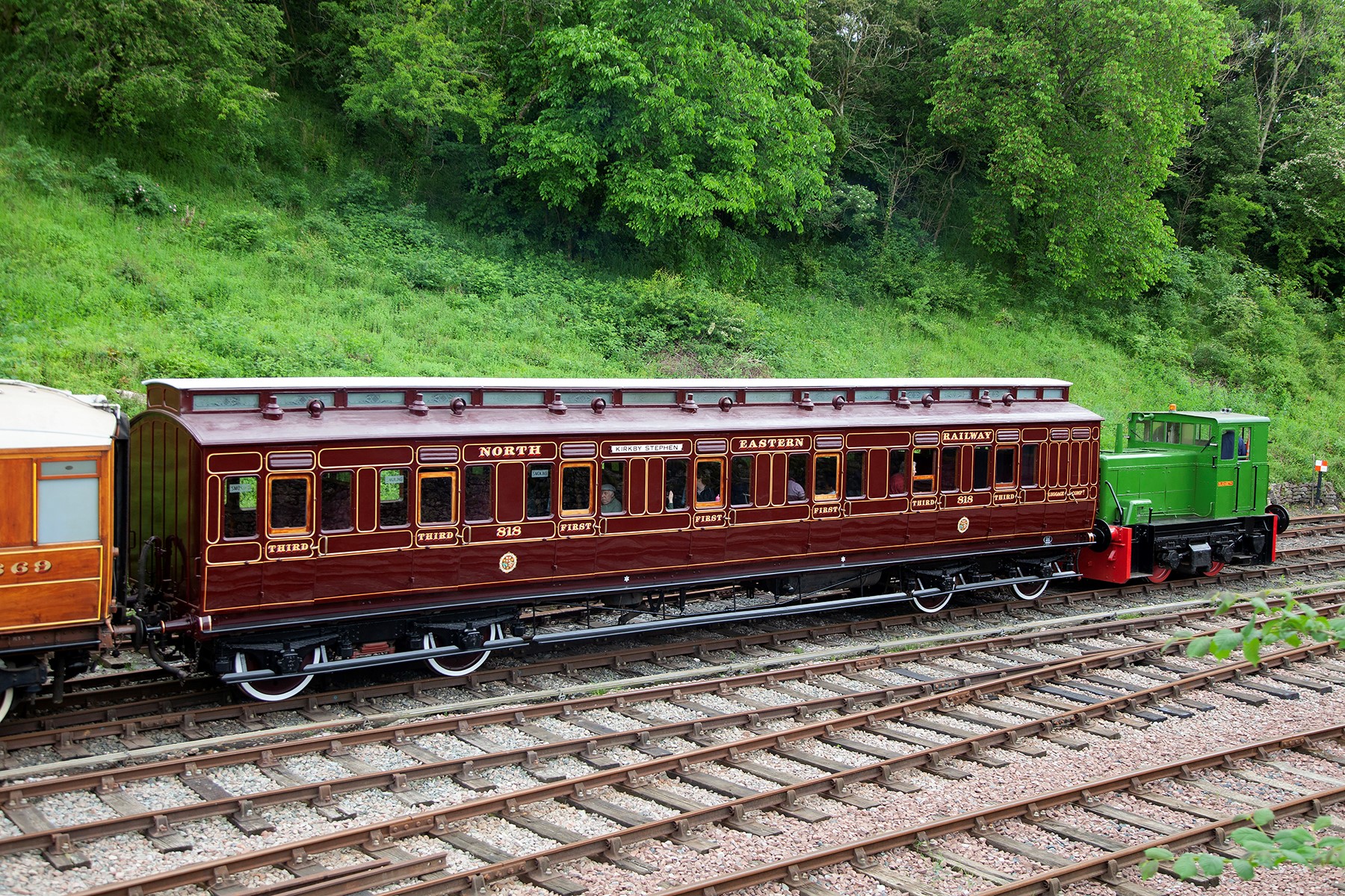
In the meantime, here are a couple of pictures of the newly restored NER coach 818 at Kirby Stephen, courtesy of the Beamish website. Does’t she look magnificant? I really must get up to see her.
Portchullin, Perth and British Railways Modelling
June is a busy month for Portchullin.
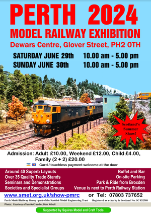
Firstly, we will soon set sail in the van to Perth with both Portchullin and Oli & Chris’ Cessy en Bois for their model railway show. The details for this are below and there are a lot of good layouts there, including the two biggest P4 exhibition layouts – Mostyn and Burntisland. So there is plenty to see even if Portchullin does not float your boat (……….as if……….). If you are visiting do please say hello.
Its a long drive to Perth from Surrey, so to break the journey up a couple of us are going to visit a number of home based model railways that you can’t see at shows. The current plan is to visit eight layouts, two preserved lines and the Perth show, so we will be well and truely model railwayed out by the end of the trip!
As you would imagine, being able to visit a number of layouts that don’t generally get seen will provoke the camera to come out andas there are a number of treats in stall, keep an eye out for future blog posts.
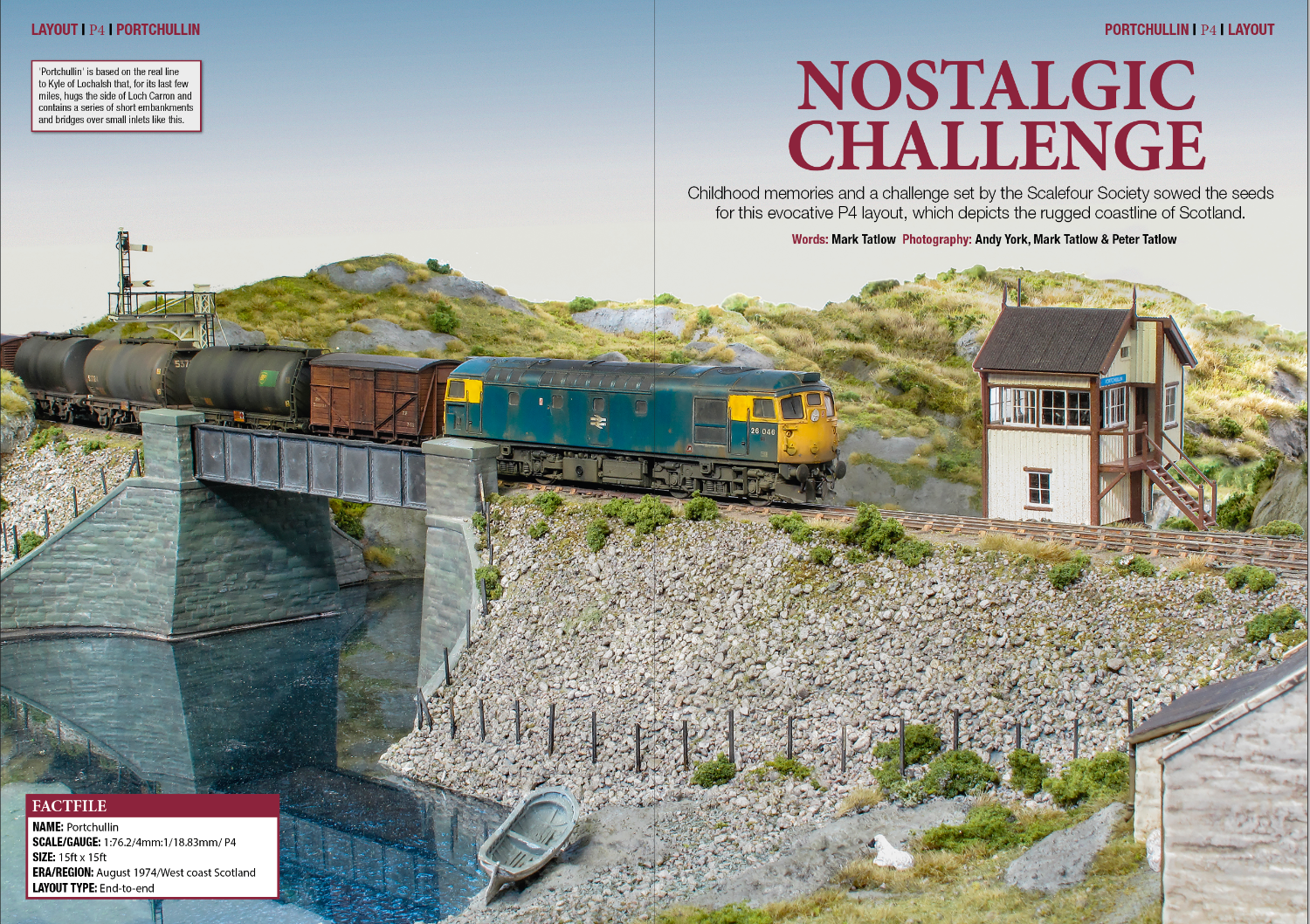
The other activity for the month has been the writing an article for publication in July 2024 issue of British Railways Modelling. This, combined with photos from myself and Andy York makes what I hope is an enjoyable article.
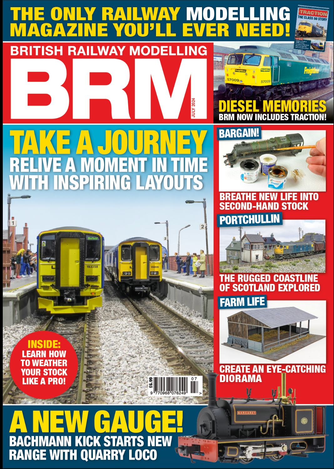
I have particularly talked about the origins of the layout and how it was conceived, with a smaller amount of information on how it was done. It should be available simultaneous with this post and if you have any thoughts on it, I would welcome feedback.

News from Miscellany Models
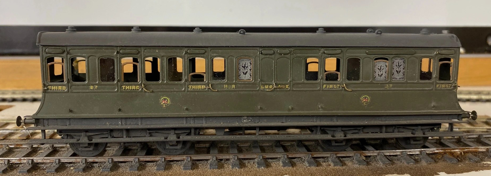
With the assistance of Duncan Petford, Miscellany Models are now offering engraved glass windows featuring the thistle emblem that the Highland used to obscure the windows of toilet compartments. They come in packs of five, for £7 postage included and are available here.
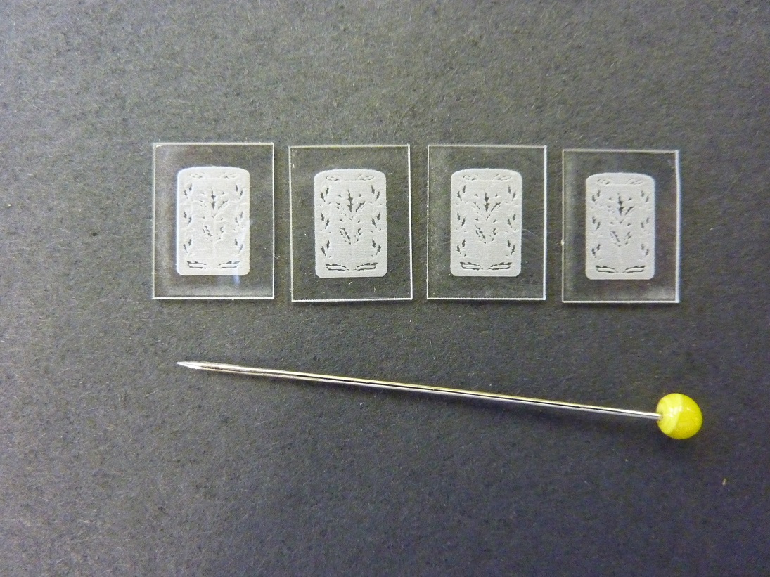
These are laser engraved on 1mm perspex and really lift the appearance of a Highland coach, as you can see:
Sadly, I have also had to increase the prices for most of the products. The costs of the last few deliveries from my etchers have been eyewateringly expensisve, so I need to defer a degree of this. The good news is that this is an indication that more products will soon be featured too – so Highland and LMS modellers keep an eye out.
The Other Benfieldside
To date, the images and details I have shown on Benfieldside have related to the main and original station. However, there is more!
Benfieldside’s original builder, John Wright, constructed a significant extension a few years after completing the core layout. This was shown at the time in the Model Railway Journal (issue 57, 1992) and has not really be seen since.
When John’s interests moved on, he disposed of both parts of the layout and in turn the new owner decided he did not wish to retain the whole. However, he elected to retain the extension in order to convert it to P4 as his home layout (Benfieldside was all constructed as an EM layout). We all know what life is like – jobs, family life and other priorities get in the way but progress is now being made. The two main lines are now operational, as these two videos show.
The new layout will be NER as a core, but with also a Midland presence. It appears that the Midland has provided the motive power for the test train!
As you can see, Benfieldside’s extension was centred around a substantial viaduct with a degree of siding to one end. Its owner is proposing to make a small MPD here, the beginnings of which are visible in the videos.
There is still a way to go both in the adjustments around the MPD but also in refreshing the scenery. But never the less, as you can see it is another impressive layout.

A Fold of Cattle Wagons
Your pub quiz fact for the day is that the collective name for Highland cattle is not a herd, as it would be for most cattle. Instead, and only for Highland cattle, the collective name for a group of cattle is a fold. If that does come up in a pub quiz, you owe me a pint!
Cattle were an important part of the highland economy and hence were a good source of income of the Highland Railway. In my slightly distorted version of real history, there were 4 million head of cattle to transport per annum in the Glenmutchkin area (which is remarkable given the cattle population of the entire UK at the time was only a little bit higher!). Thus, a fold of cattle wagons was obviously a pre-requisite for Glenmutchkin and this is what I have been working on of late.
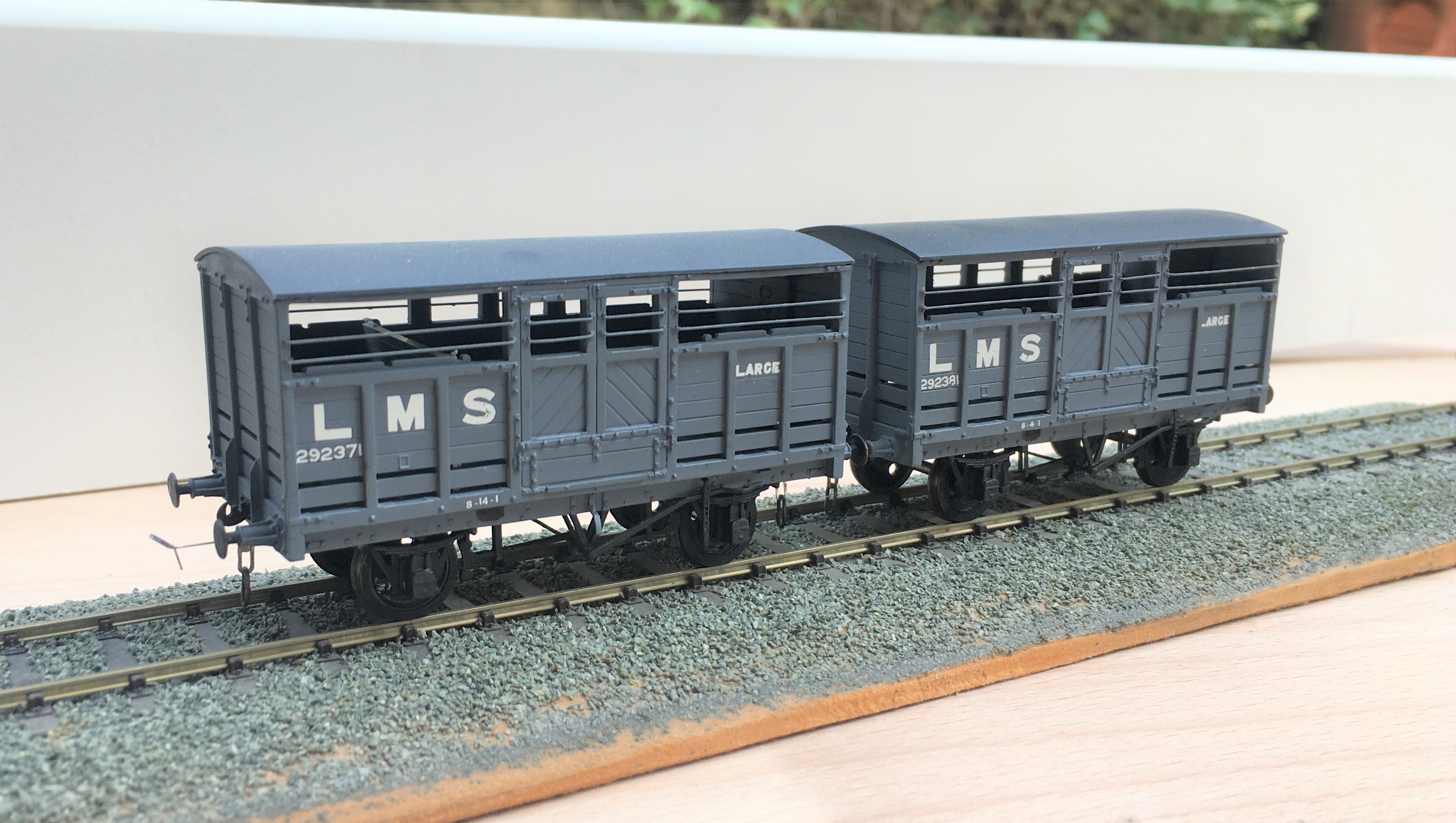
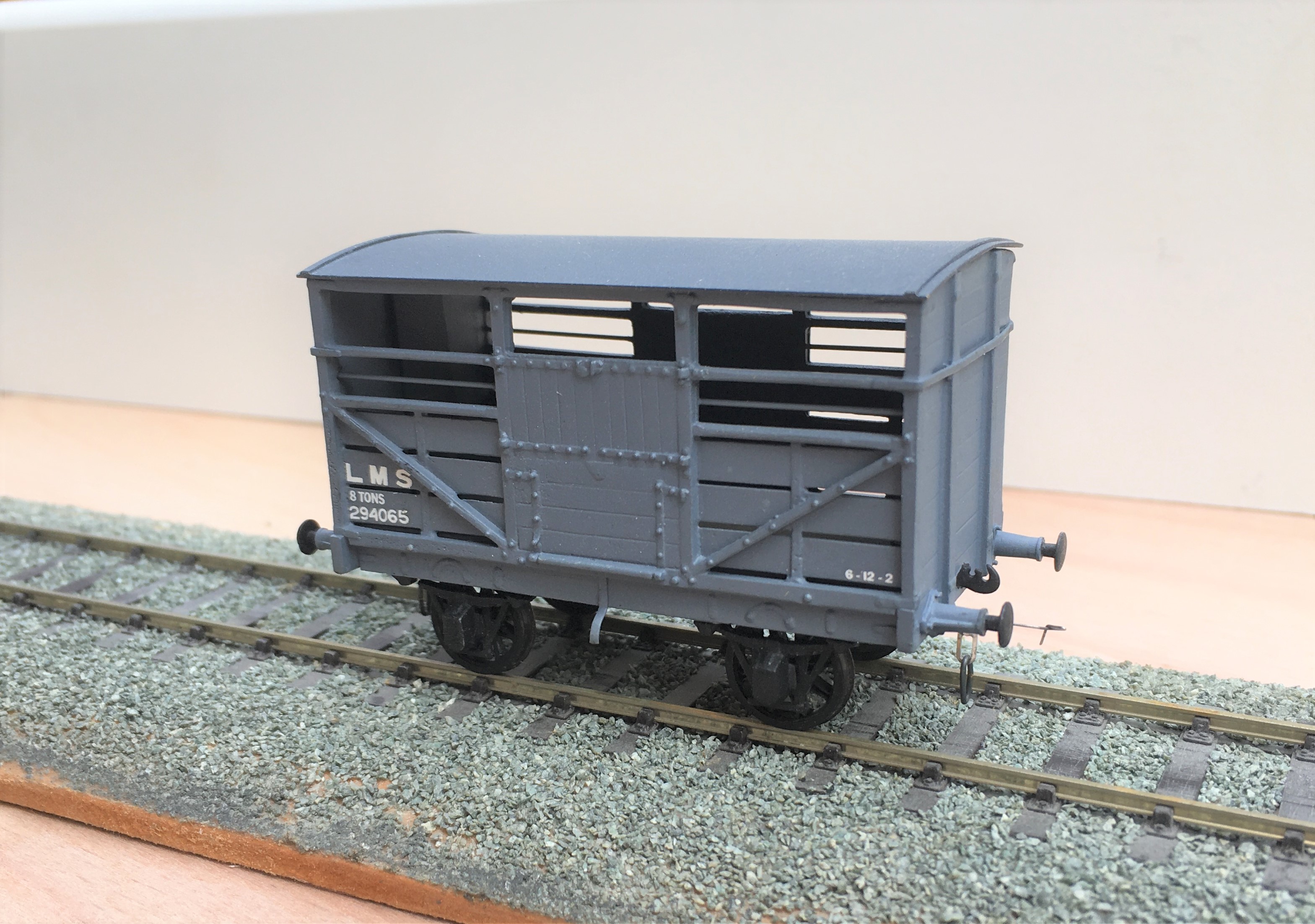
First up are a pair of LMS standard cattle wagons; to diagram 1661. These date from 1925; so they would have been fairly new at the time that my layout is set in. These were built from Parkside plastic kits with only moderate modifications around the break gear and, of course, some sprung w-irons. Being a relatively recent kit, it is generally very good and whilst it is possible to convert it to some alternative variants, these came later than my modelling period so I was not tempted. I am concerned that I have painted them rather to dark though, so I will be weathering them on the light side.
Next up is a Great North of Scotland Cattle wagon, from a Model Wagon Company white metal kit. This is a much older kit and didn’t it felt it! For reasons I am not certain of, the two sides were not the same length so in practise the body is a bit trapezoidal – but can you tell? The casting was also covered in flash which was a particular problem in the gaps between the wooden slats – this meant I spent a few hours I would sooner not have spent scraping it out to keep these clear. The GNoS vehicle was a much more basic vehicle and, strangely, did not get any large ownership lettering so they remained rather anonymous, Instead, they had simple cast plates, which I made from a locomotive number plate and dry brushed white on the letters. I have glossed over the fact it does not have the right number or even a consistent number from one side to the other – sod the “getting it all right” mantra!
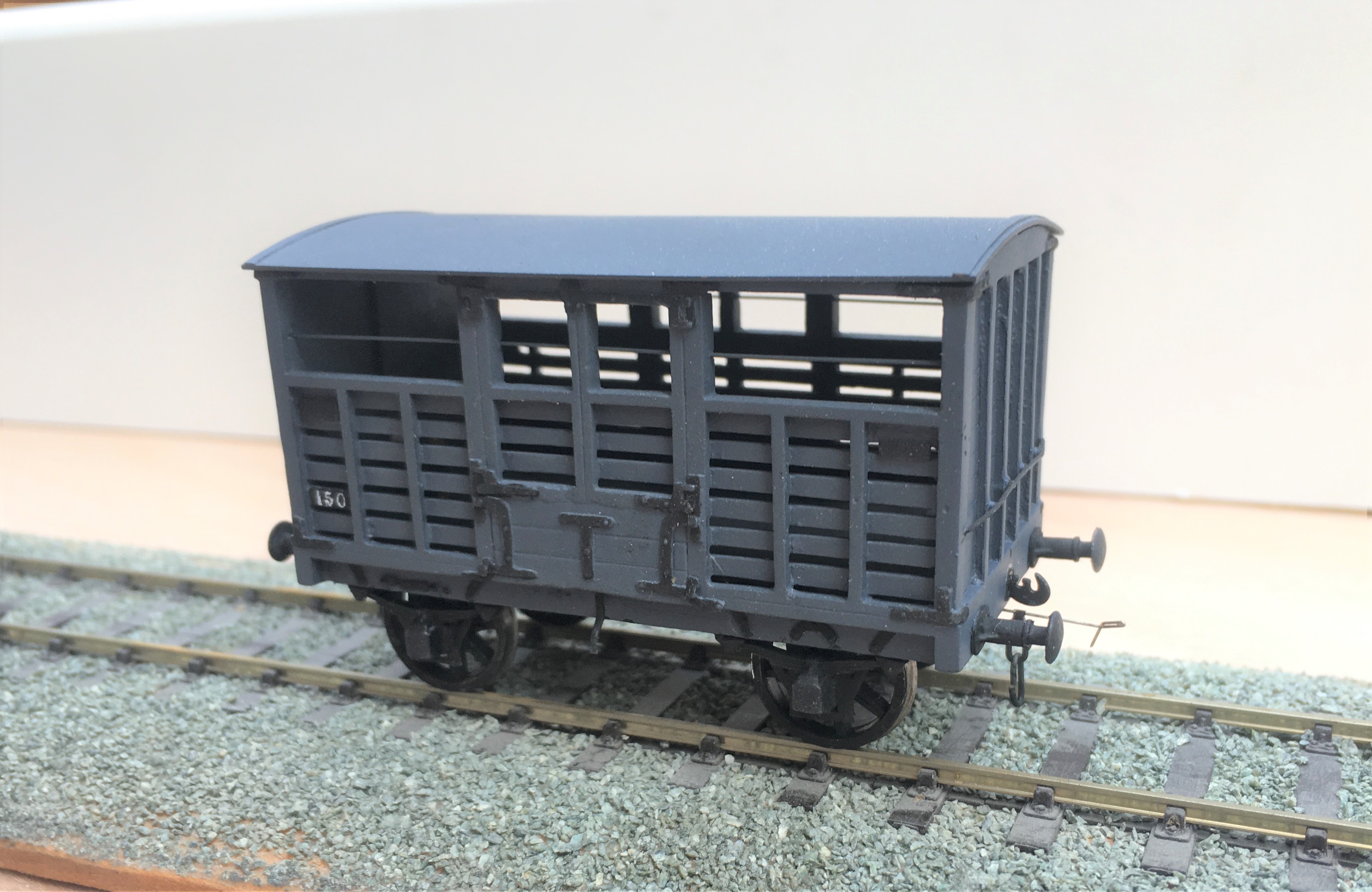
I have also built a further Highland cattle wagon, built from a Model Wagon Company kit. This is the Drummond era version and I have already built a number of these so this was relatively routine – its just as well as there are still a couple in their packet waiting their turn!
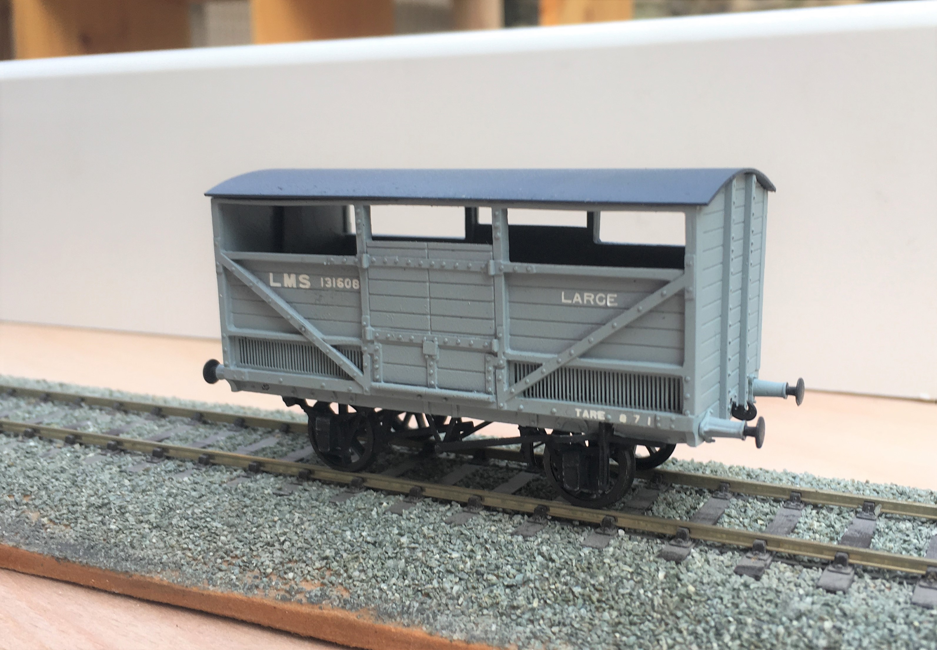
The final cattle van is a David Geen kit for the L&Y large cattle wagon. Whilst still a whitemetal kit, it is of somewhat better quality than both the Model Wagon Co kits so was rather easier to make. Even then, it did need filling at the corner joints and I felt the need to swap the brake levers for replacements – why to even the better manufacturers use the same material for all of their kits?
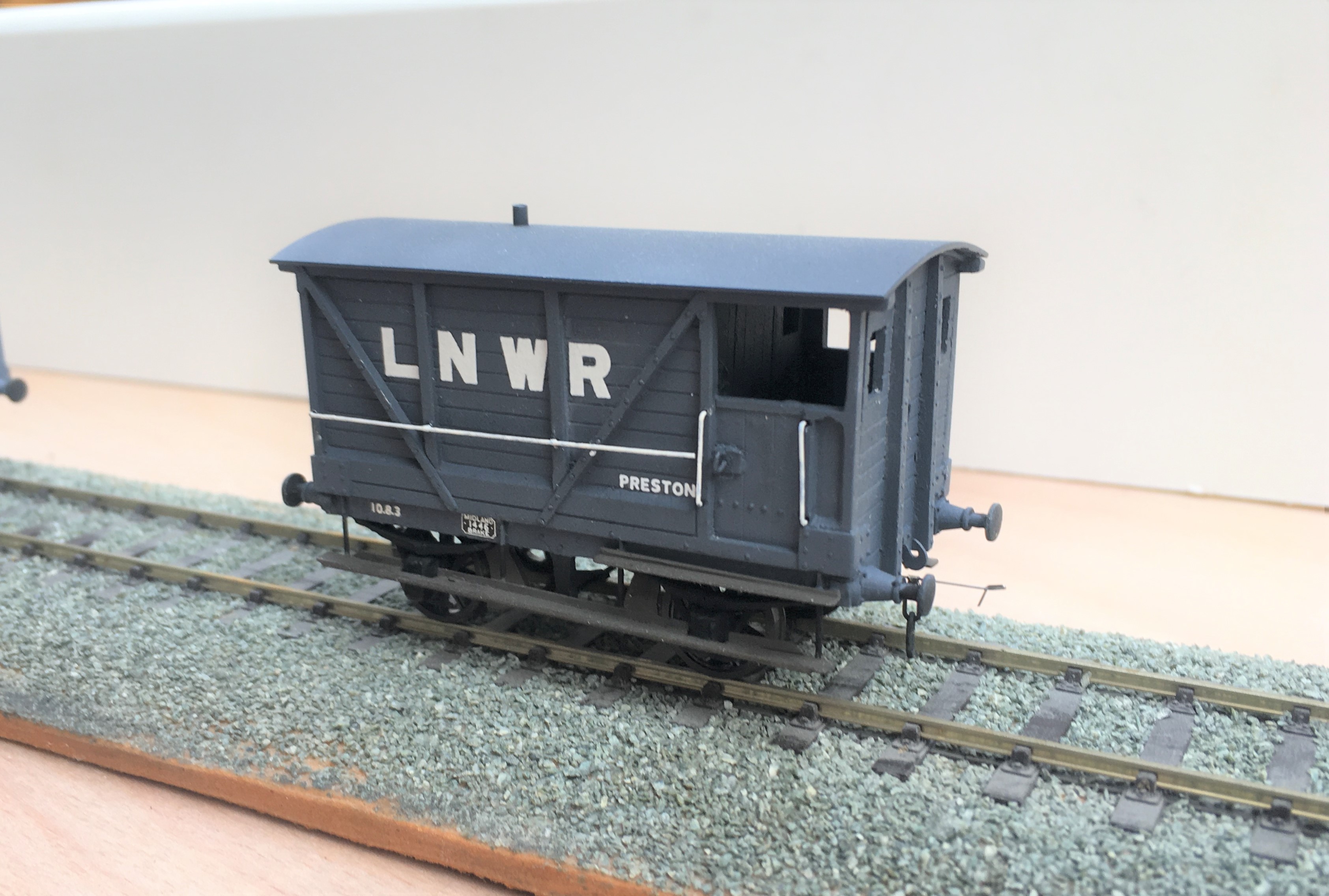
To finish of this little rake, I obviously need another brake van. This is not so obvious because this is brake van no 11 in the collection and I know I have at least one more spirited away! Whilst this was a kit build, it was first a kit unassemble as this was a vehicle I had first built in my teens. Generally fairly well but a couple of bits had got damaged over the years so I felt it needed rejuvenating.
And here they all are on parade.
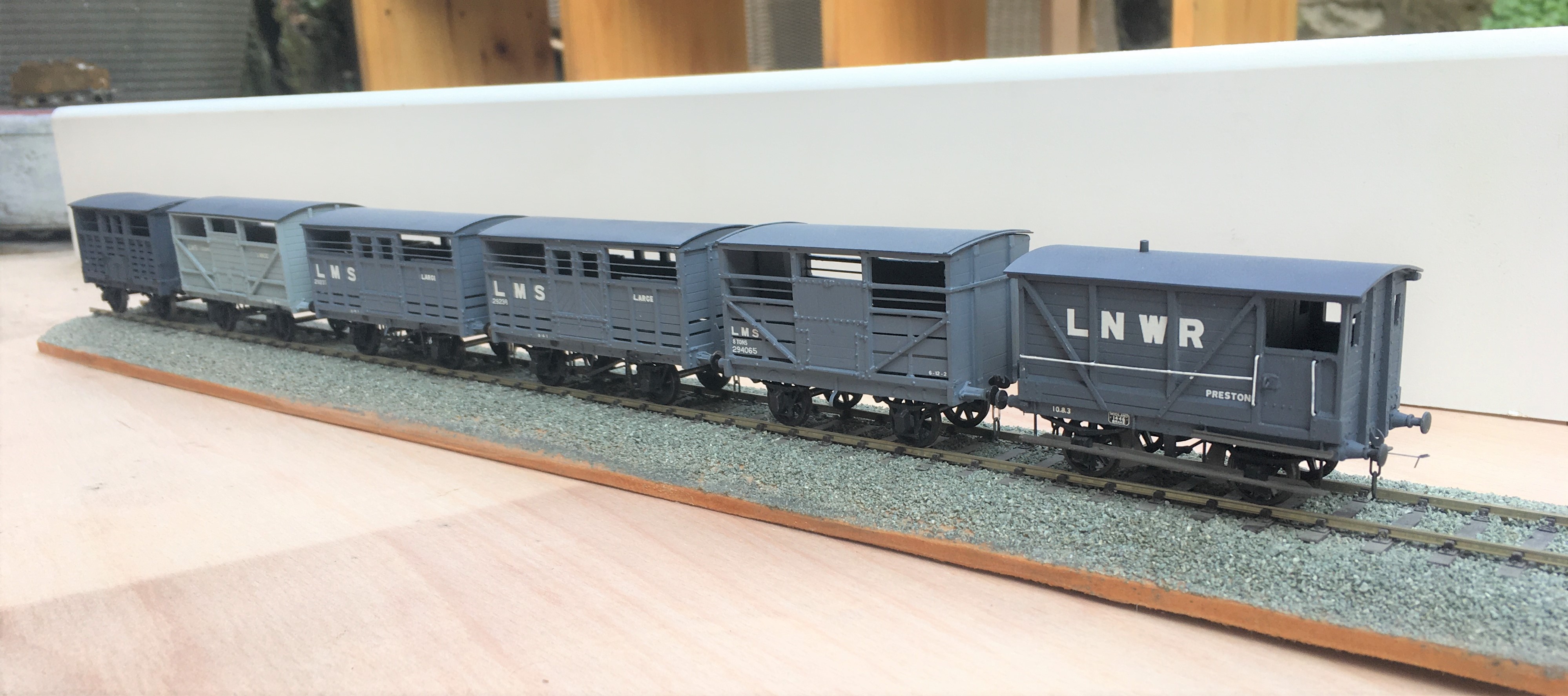
Now all I need is rather a lot of heilen coos to fill them up with. I have been working on this but it seems that resin casting is a tad more difficult than I thought……………..
Oh and yes, they are all way to clean; another weathering sess’ is required guys………..
Scaleforum at a Screen Near You Soon!
With these strange times that we have been experiencing for the last six months, we have all become a bit cooped up in our abodes. Whilst the lack of model railway exhibitions is hardly going to make the six o’clock news (can you imagine!), I for one have missed both the inspiration and the camaraderie they offer.
We have not seen a plethora of on line exhibitions so it is welcome news to see the Scalefour Society making the effort to arrange one in place of their annual exhibition. This will “take place” on Saturday 26th September between 10:30 – 5:30 although it seems much of the content will be available thereafter online. Here is a trailer for it:
In addition to seeing familiar faces again, I was particularly struck by the possibility of seeing a number of “home layouts” that we don’t ordinarily get to see – and some big ones at that!
Some seems to be by video and others by an interactive youtube link so that you can chat to the team/person. This is the listing of what is proposed.
Layouts:
Boston Frodsham by Mike Knowles
Bristol Barrow Road by Robin Whittle
Central Cheshire Lines by John Sherratt
De Graafstroom (P87) by Vincent de Bode
Drighlington and Adwalton by Steve Hall
Eridge by the Kent Area Group
Faringdon by Rex Davidson and Stephen Williams
North Elmham by the North Norfolk Area Group
Obbekaer (P87) by Geraint Hughes
Pwllheli by Jonathan Buckie
Southwark Bridge by Mike Day
United Mills by Ray Nolton
Demonstrations
Adrian Musgrave – Signals
Alistair Ford – Timber Buildings on Black Gill
Brian Hingston – Coaches
Chris McCarthy – Baseboards
Dave Keeler – Wagon Construction
David Brandreth – Resistance Soldering
Jim Smith Wright – Soldering White Metal
John Farmer – Scenics
Mick Moignard – DCC Sound
Nick Rogers – Wagons
Rod Cameron – Lewis Project
Stuart Holt – Tree making
Illustrated Talks
Martin Nield – Authentic Model Railway Operation
Jim Summers – ‘Earning a Living’
I can see that chunks of the readership of this blog are dispersed in far flung places – take some time to see some really good 4mm without burning your air miles. The details to the log in can be found here:
So I know what I will be doing with much of the 26 September…………………. I will even make sure I have done some on-line shopping at about the same time so that Scaleforum hits my pocket in the same manner as usual!!
