Category Archives: Glenmutchkin

Calming an Exhibition Manager’s Nerves…………
So with nine weeks to go (a couple of which will be lost with a summer holiday) to Glenmutchkin’s first outing at Scaleforum, the state of progress is at the forefront my mind! It is probably rather more at the forefront of the exhibition manager’s mind!
So help to calm the Scaleforum’s exhibition manager’s nerves, here is a progress report and update photographs to prove that even if I have not been providing many posts, progress is being made on a number of fronts:
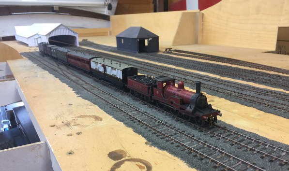
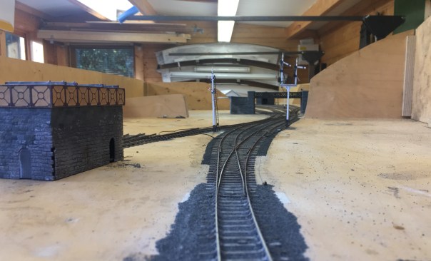
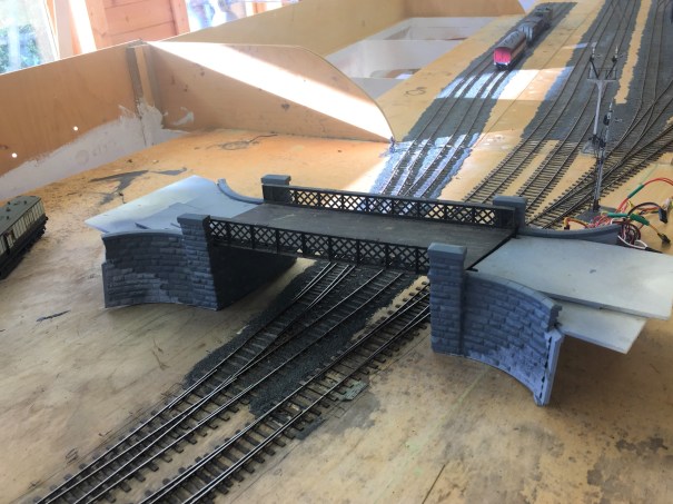
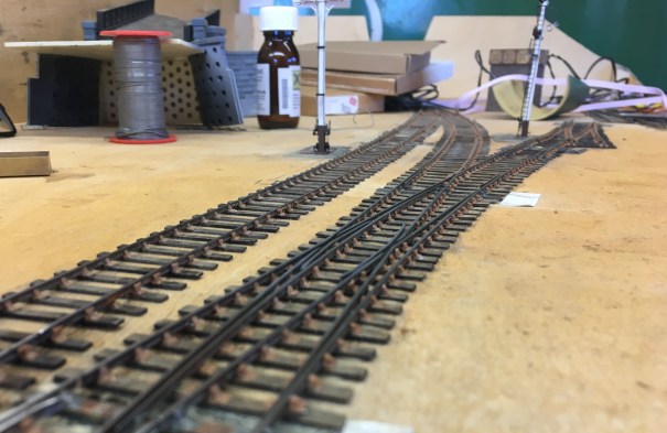
Most of the track is laid and wired; much of it is also ballasted, although it still needs colouring.
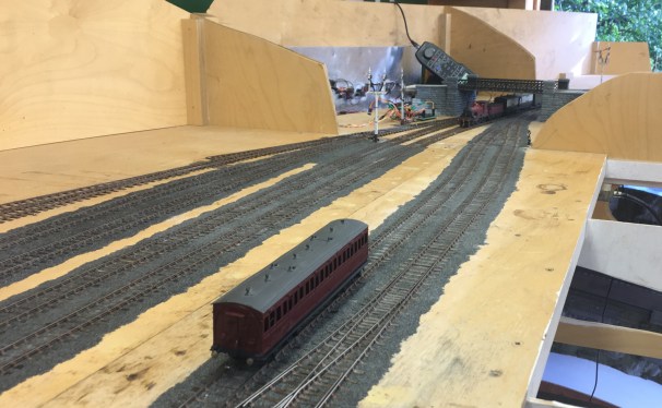
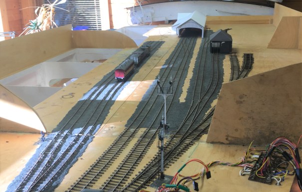
Most of the signals are finished but not yet linked up (which explains some of the droopy angles of the arms!). There will be more posts on this topic soon.
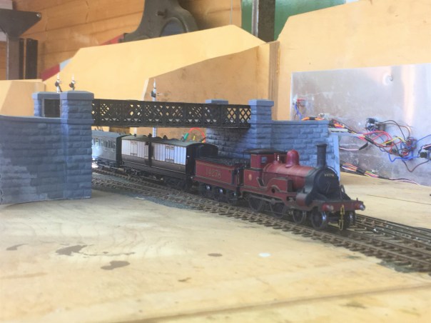
The principal bridge has been finished for a while, but it is looking a bit more “at home”.
…..especially with a fine loco to set it off.

Boxing Clever
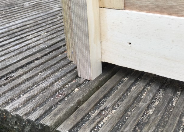
One of the worst parts of Portchullin is the lack of thought I gave to transporting the layout about. One of its attractions is the curve which makes it unusual but this makes the boards big, cumbersome and above all awkwardly shaped to transport. It also made them difficult to create packing solutions for and the limited solutions that I adopted have never been good enough which has plagued the layout throughout its life.
It was a mistake I am anxious not to repeat with Glenmutchkin and now that it is beginning to accumulate some finished elements, it is definitely time to deal with this and create some cases to enclose the boards when they are either stored or transported. My requirements for these were that they provide rugged protection to allow the layout to be transported without risk of being damaged. I also wanted them to be easier to move, in particular on my own, and to pack away themselves without taking up significant amounts of space.
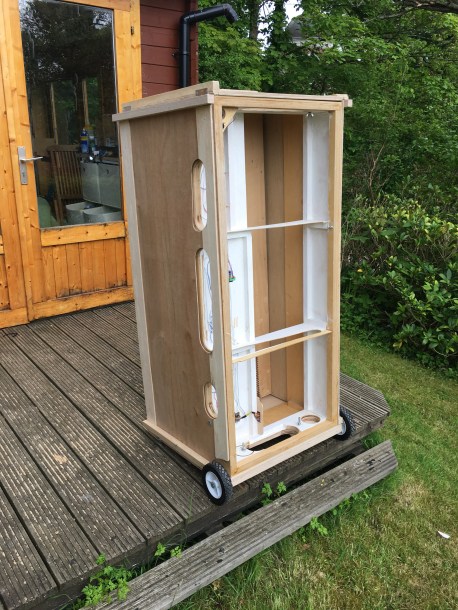
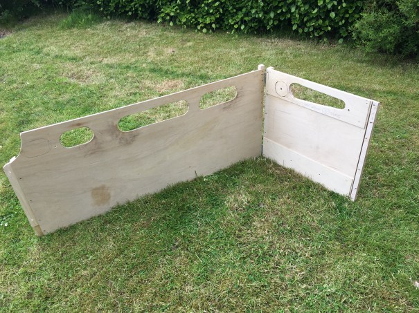
There are (presently, there are plans……) six scenic boards and the crate for the first two – for the smallest boards – is now complete. The concept I came up with is to use end pieces that secure the two boards on top of each other, face to face. To this, I have added larger panels to close in the sides and prevent these exposed parts from damage. To try and speed up assembly and also reduce the space that they need, each end is hinged to and end piece but conceived such that they fold onto each other so that they pack into the minimum possible space.
One of the other features I included was nicked from the St Merryn team was to introduce packing pieces to make sure that the ends stand clear of the rail ends. A simple feature that I had not seen described before.
To make the combined case and boards easier to transport I have introduced some trolley wheels – the operating crew are pretty excited with this and can hardly believe how much they are going to be spoilt! The other little trick I am please to have employed is to introduce slight feet to enable fingers to get below the box to lift it.
I have concluded that only the two smallest boards can be paired up in this manner as they are already quite heavy and will get more so as I add the remainder of the features to their topsides. Thus the remaining board cases will be slightly different.
")
Take a Chair (….err, actually a few thousand!)
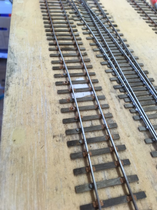
Of late, I have been getting on with one of the more boring layout building jobs; that of adding cosmetic rail chairs.
As I wish to retain the flexibility of soldered track construction (basically because I do not trust myself to get it right the first time!), it is necessary to affix cosmetic chairs at each sleeper. I did lesson the task by using part soldered/part chaired plain track but even so I reckon there are three thousand chairs to affix………..
It does, however, make a big difference and the track is now beginning to look real – as you can see below.
I am over half way and so it will soon – which is just as well as filing the chairs ready to lay is wearing my thumbs and fingers out to very sore digits!
Arguably though, chair fixing is a form of procrastination because i must finish the wiring and then confront that turntable again!

Another Wordless Wednesday……
…………again because I cannot put the words I would like to use on a public blog!
This was the scene that confronted me over the weekend when I was trying to fettle the layout for operation – a good number of broken chairs and detached solder joints. All this resulting in some fairly severe gauge narrowing!
It has been fairly warm here in blighty (I know that is a relative concept to some of the readers of this blog in the more far flung corners of the world – the Brits like to moan about our weather!). This has resulted in some thermal expansion and clearly I have not allowed enough joints to absorb this. It will be simple enough to fix, but altogether a pain.
Perhaps more irritatingly (because it has happened rather more), it has closed the gap on a number of crossings. This has resulted in a fair few short circuits and a campaign of dealing with these has taken a good chunk of my Sunday up!

The Glenmutchkin Pharmacy – Part 1 The Etchings
It is a fair time since I built my last building, so feeling that it was time that I rediscovered my mojo for architectural things I have made a crack at a building that will be a fairly key feature on Glenmutchkin – its pharmacy .
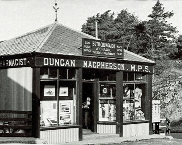
This is inspired, and largely a facsimile of, The Kyle Pharmacy that could be found on the approach to the ferry pier. Or at least it could until the 1970s when it was swept away to make a larger car holding pool for the ferry. In addition to being a characterful building, as you can see below, the real pharmacy at Kyle was a key part of the local community and I wanted to capture this feature in Glenmutchkin.
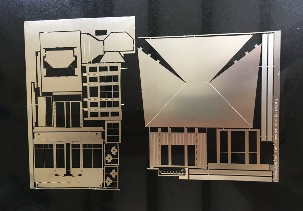
The pharmacy building is going to be located on the most prominent position at the front of the layout, so it definitely deserved some time being spent on it. Taking Peter Bond’s advice, it is going to be assembled in components which will make painting a great deal easier but rather than using plasticard throughout as he would have done, I have arranged to have the shop front and bay etched. I did so as I concluded that getting the slenderness and crispness of these was going to be key to get the feel of the model convincing. Peter is a professional architectural modeller and bending plasticard to his will is therefore his stock in trade – not quite so me!
So these are the basic etches back from PPD:
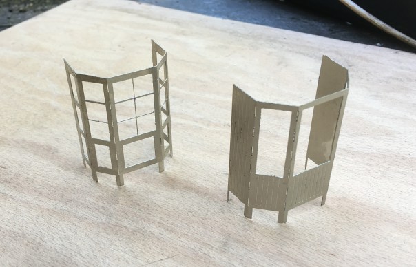
Some of the bay assemblies and the bay largely completed:
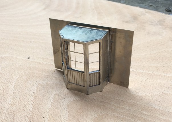
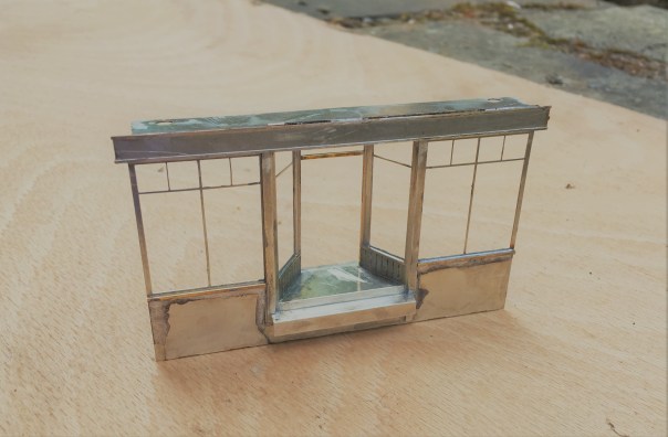
The real value of etching the components can be seen in the shopfront – I at least can’t get plasticard to look like this!

Slip Ups – There is an Easier Way……………
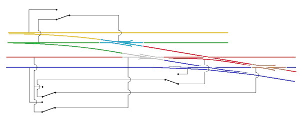
My last post recounted the difficulties that I was encountering correctly wiring up a slip and the technique I had arrived at to overcome this, This precipitated various bits of advice including an alternative approach provided by Richard.
Richard’s solution is certainly a little easier than my approach to wire and does not need an additional point motor to run the extra switching required. It is, however, slightly less idiotproof in use than my version – this is because once the approach turnout is set for the branch in my version, the whole of the run was also set electrically. On Richard’s version, it is also necessary to decide whether the main line to yard is to be set for the yard.
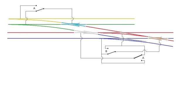
This is what it looks like as a wiring diagram and it is important to note that the approach turnout (A) is also operating one of the slip’s switches too.
I need to fire up the soldering iron now and undertake the correction, so that we can play with trains!

A Bit of a Slip Up…….
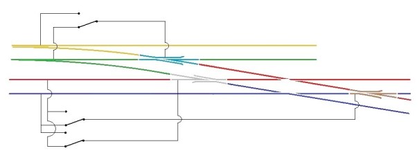
I have been continuing with the wiring of Glenmutchkin, but have hit a snag; one that I should have been ready for – the wiring of the slip, I had been aware that a diamond crossing was a challenge to wire and I was suckered into thinking that the switches on a slip could over come the challenge, Well I go that wrong…….!!
The basic problem is that there are a choice of two routes through a diamond crossing and each route requires the polarity of the crossings to be different. The diagram below, which shows how a diamond crossing needs to be wired, should illustrate the problem. The only solution to this is to power the crossing polarity by way of an approach turnout – if you really don’t have one to set the polarity with, then you are going to have to resort to some switches – but at least it will give you a good excuse to interlock the diamond crossing with some signals to remind you on which direction it is set!
Hopefully this is clear that the crossings on the diamond crossing are activated by detecting the direction of the switch on the approach turnout. If it is set for straight ahead, then a train can’t travel over the crossing and therefore the parallel line can so the polarity of the crossings are set accordingly. Conversely, when the approach turnout is set to the branch, the line across the diamond can be used and the polarity is set to suit.
The principal with the diamond crossing needs to be heeded when the crossing is replaced with a single slip as I have, but it does get more complicated because the switch of the slip can also lead to a different route through the crossings. The crossing to the left of the slip is the more straight forward as it is only activated by the approach turnout. However the right hand crossing is more complicated as if the approach turnout is set for the branch then it always needs to be in the red polarity whereas if the approach turnout is set for the main, then it then needs to be controlled by the slips switch.
Hopefully the diagram above shows how this works.
The irritation I have, in addition to having wired it up wrong already (!) is that the approach turnout is on a different board to the slip. To reduce the number of wires crossing the boards, I have decided to simply use a duplicate point motor for the approach turnout located on the same board as the slip. It is expensive but rather more simple than the additional wires.
NB – please see also a follow up post on this wiring arrangement for an alternative approach.

Two Steps Forward and One Back
Having taken a few days off to make a long Easter break and absent the family for a few days, I have set about the wiring of the layout as it has laid untouched for too long!
First things first was to mount the control panel and rather smart it looks too……….
Control panel mounted in situ; a gap for the controller to the left and the aluminium strip to the right masks the power district switches.
Then onto the wiring itself, which takes a surprisingly long time…………….this is only about 50% finished!
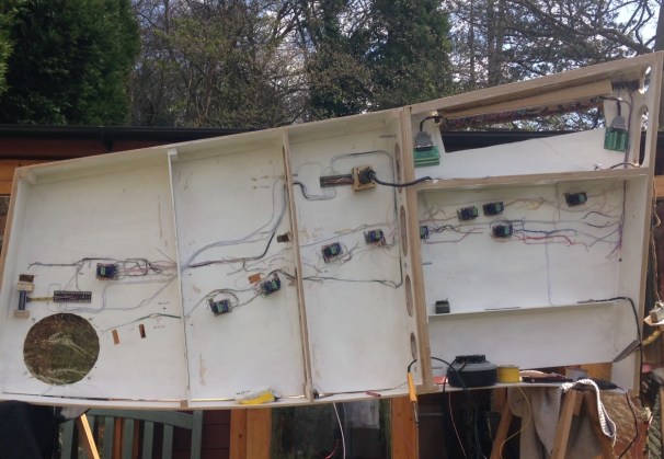
The two key boards to the station throat
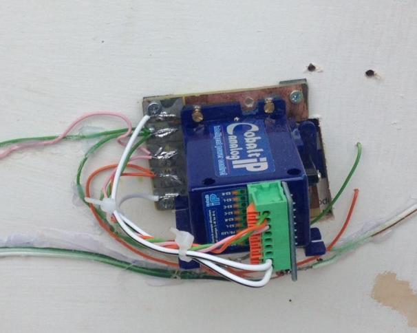
One of my slightly better ideas (you’re about to find out about a less good ones!) has been to make up mounting pieces for the DCC Concepts Cobalt point motors. These are inspired by those designed for the Tortoise units and work on the same principal; they have a uniform mounting arrangement so once set up the actual point motor can be swapped over if need be without disturbing the set up. This is what they look like:
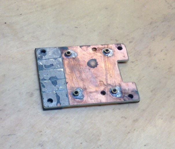
Cobalt Point Motor Mount
Nothing too revolutional, but I hope it will make changing these at exhibitions a lot easier as this is the absolute devil on Portchullin.
And the less clever idea? Remember the multigang sockets I had used on the control panels (link here) well they are not rated at a sufficient capacity to operate the point motors. I think this is because Cobalts operate on a stall basis (the motor doesn’t turn off, it just stalls when it reaches the resistance of the physical stop). My guess is that this results in quite high ampage draw and has led to the following:
The multi-gang sockets with burnt out sections to the left.
Ooops! Back to the drawing board (or rather traditional tag strip) for the linkage of the control panel to the board.
There have been other problems too; the carefully recorded wiring lists proved to be wrong on occassions so I have had to prove each cable run (dooh!) and I found one of the power district switches was defective (but only after a couple of hours of trying to trace the fault!)
So things are getting there, but we are still not at the stage of the first wheel moving!

Nothing to See Here
Well, that’s true of the top side, where nothing visible has happened of late but there is progress when you look underneath.
I have spent more than a few hours soldering dropper wires on about half of the track that has so far been laid. All is neatly colour coded (hopefully).

Another development in comparison to Portchullin is the painting of the entirity of the underside of the layout white. This is to make everything clearer and will, hopefully, make it easier to deal with issues with the layout set up – although I am hopeing for less issues!
Even more hours (weekends even!) have been spent making up jumper connections, so hopefully the wiring will speed up in the coming weekends! I have spent this time to work through the logic of the wiring across all boards and there is a full wiring schedule in place – none of the wonky logic on Portchullin this time!

")
Christmas Layout Wiring (Not!)
I promised a number of people that I would be making sure that the layour had at least the main elements wired up over christmas, so that it could at last run. But then it was a bit wet and cold so I did not fancy it out in the summerhouse so I applied rule no 1 – its my trainset!
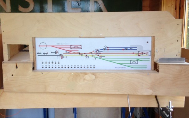
Instead, I stayed at the bench and made a pair of the signals that still remain to be made for Glenmutchkin. The signalling plan has developed very slightly since I originally showed it back here and is shown below (actually this is the artwork for the control panel facia).

The signals that I built were those that control the main loop prior to the shed link – levelrs 27 & 28 – and then the outer starter (that covers both the main loop and the main line) – levers 23, 24, 25 & 26. Only a pair of two doll signals, I thought, they shouldn’t take more than a day or two? Phew, well that wasn’t right; the more you look at the prototypes, the more you find there is to model!
Having created much of my own etchings and castings for MacKenzie & Holland signals I have obviously made good use of these. In this case, the small brackets, arms, ladders and castings.


Both of the signals have used the small brackets to create smallish landings. The smaller of the two signals has only one arm per doll, the larger two. The dolls and the posts are made up of square brass section which is filed to a taper – a certain amount of elbow grease is needed to acheive this! The posts are then sandwiched between some transom beams that also clasp the doll post – this is all soldered with a high melt solder to stop it ungumming later.


The brackets are then offered up from below, with scrap etch forming the bearing plates to pick up the transomes. In the etch I also included smaller brackets to pick up the free end of the landing, along with the landing itself. This gets you to the stage shown above.
But this is not the half of it on a signal, there are the finials, lamp brackets, lamps, cross stays, access steps, access ladders, pivot plates, handrails, operating cams, safety hoops and ladder still to do………..
 .
.
In a departure from my previous practise, I made the main ladders detachable (they will be held with the wire that can be seen in the pictures being turned over in secret pockets. I am also going to paint this prior to the final assembly; which will mean some touching uo of the painting later but I hope will make it easier.


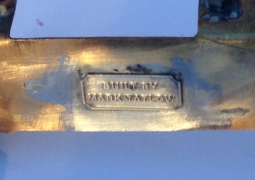
And of course, I had to sign them with these rather nice custom name plaques from NBR 4mm Developments.
This is the first time that I have used the brackets in signal making and I was pretty chuffed with how they have come out. This is where things presently stand and we head for the paint shops tomorrow…….


