Category Archives: Glenmutchkin
Brighton Road and Some Etch Masters
Less modelling has been achieved this week – due to a combination of work taking me a little more afield than normal and also because I was playing with someone else’s trainset.
In this case, the layout was Barry Luck’s (with assistance of the Mid-Sussex AG of the S4 Society) Brighton Road. It was shown in the carriage repair shop at Horsted Keynes; so we were serenaded by the sound of the real thing (and the occasional burble of a Sulzer as they had a class 33 working too.
Some rather nice photos from Jonathan Hughes are here:
and if you wish to see anymore; then go to here http://www.flickr.com/photos/nimbus20/sets/72157634415164752/
I was not totally idle otherwise, as I have had a bash at producing my own artwork for etching. I think this (it is a bracket for a signal a little like the one here https://highlandmiscellany.com/2013/02/03/first-signal-for-glenmutchkin/) is capable of being etched. I’ll be submitting it too Grange & Hodder soon to find out!
Whilst I appreciate that there are many that are now quite experienced etch designers, even if this started as a means to forward their own builds, I am still taking first steps in this direction so I am pretty proud of the above. Mind you, I might be counting chickens before…………….
No, this is not the end. It is not even the beginning of the end. But it is, perhaps, the end of the beginning. Interlocked Lever Frame – Part 4
With thanks to someone else for the quote.
I managed to get all of the locking bars, installed over the weekend and the dogs (the teeth that engage in the sliding bars) to get the interlocking going. And this is what I get to:
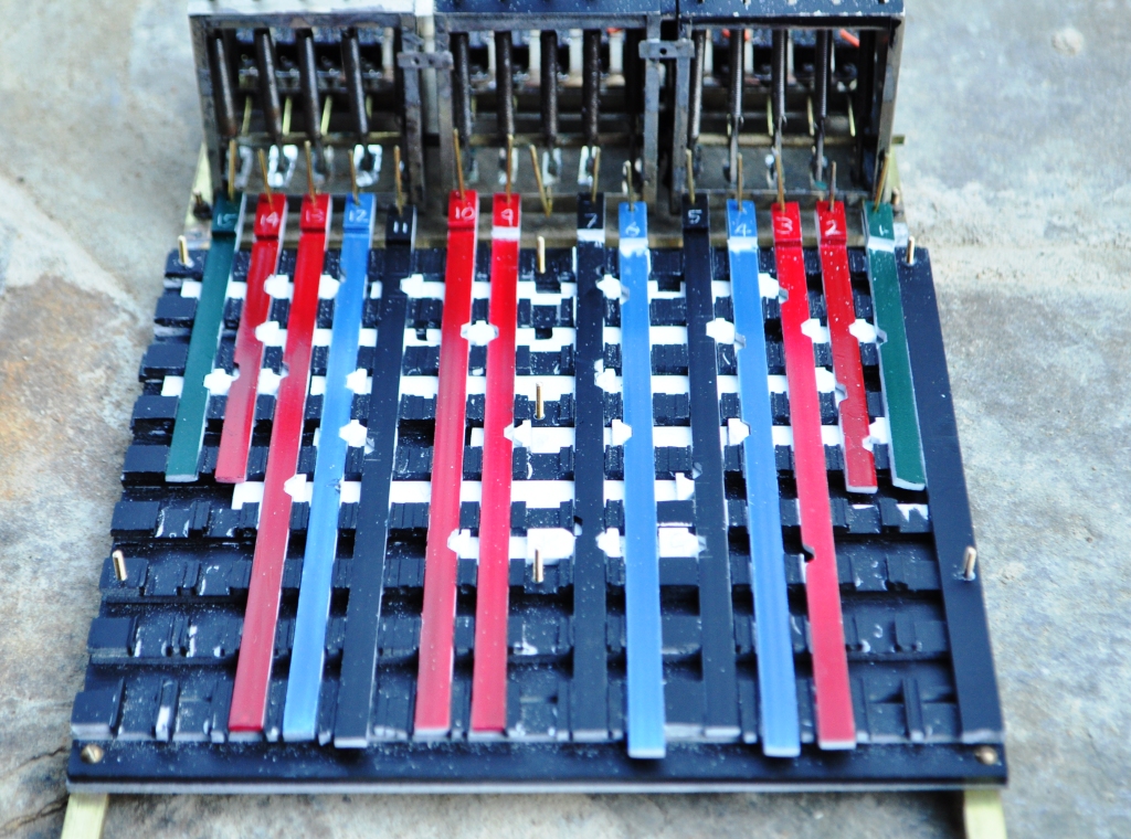
This shows all of the components assembled in place. The dogs engage in slots in the sliding bars but the dogs have angled sides – so if nothing holds them in place the movement of the slider pushes them to one side and the slider can move. When another slider is in the way (ie there is an opposing lock set) then this can not occur – so it locks shut.
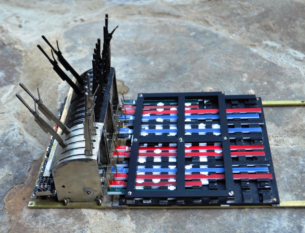
To stop the sliders popping up when they encounter a lock, a lid has been fashioned. I wanted all of the locking to remain visible, so this is just a skeleton.
I did find that the angles of the slots needed to be just over 45 degrees for the locking bar to move easily and they also need to match the dogs quite neatly. If I do this for real, I think some lost wax masters and then castings will be required to ease the process of manufacture.
The frame does lock well and neatly. Of course I made a few errors in where slots were to go but having made it from plastic, these were actually quite easy to sort out. What is more significant is that there is some slop in the levers – this occurs worst where the yoke of the bar that runs through to operate the toggle switch and sliding bars goes over the base of the lever. The hole in this is a bit too big and it means that the lever can move 30 % of its intended movement before it makes the sliding bar move and hence encounter the lock. This does slightly defeat the object of the locking and will need some work. I have an idea of linking the two more physically but if this does not work, then it may be back to the drawing board.
All in all, it works though and it is quite fun working through the desired move, working out what then needs to be thrown and in what order – although this may send my team a bit over the edge in the heat of an exhibition! However, some manufacturing refinement is going to be needed to make it work better. I remain tempted to use the potential kit that might be available but this makes the locking invisible and I am not so certain about this. Food for thought!
Interlocked Lever Frame – Part 3; the experiment continues
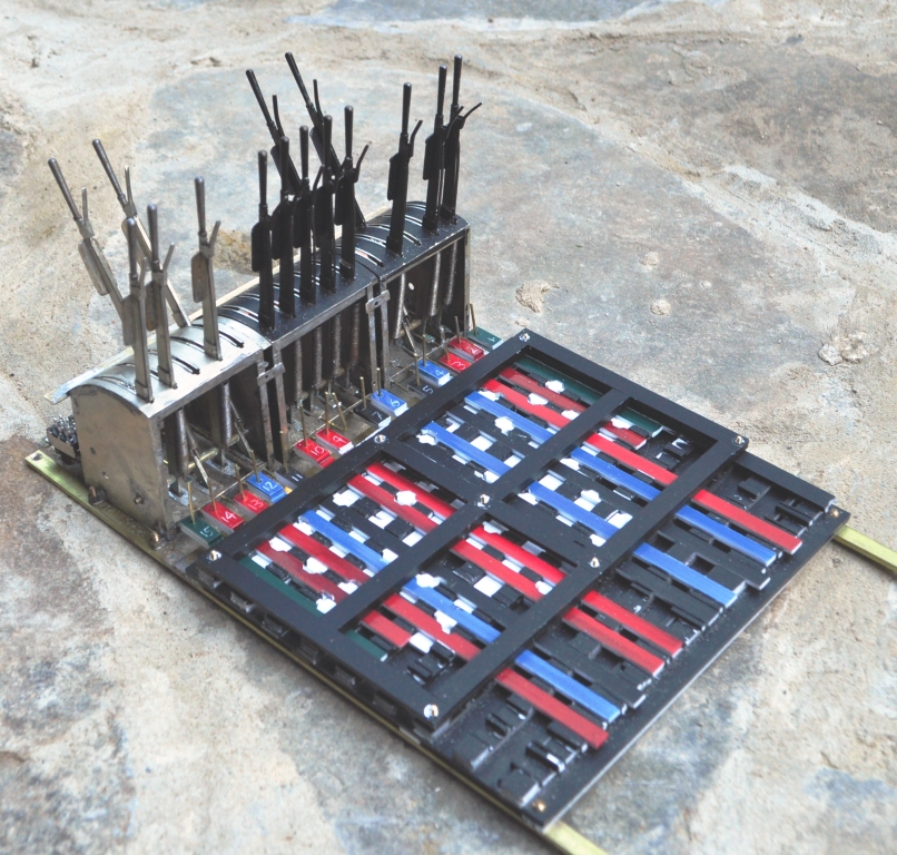
The saga continues and I have now made all the trays and the bars that the locks go into. As I have yet to colour the actual levers on the frame, I have coloured these to ease my understanding of things.
As this is an experiment, I am making this out of plasticard/evergreen strip to speed construction. The final thing will be in soldered and milled brass. I have yet to come up with a plate to secure all these bars in place, so they will not flop out as they presently appear that they might. This is what we currently looks like:
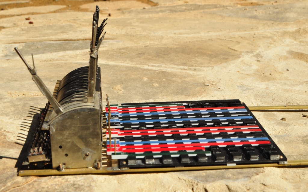
I have been warned that I may snap my tappets from the locking bars or something else. This is due to the significant mechanical advantage that the lever has over the through of the bar – if you look at the end view you can see that it is about 10:1, so I can see why I am being warned. Ultimately this is an experiment so I will take it easy with the frame if it breaks I will know that it will need to be tougher next time!
Interlocked Lever Frame – Part 2; More Experimentation……
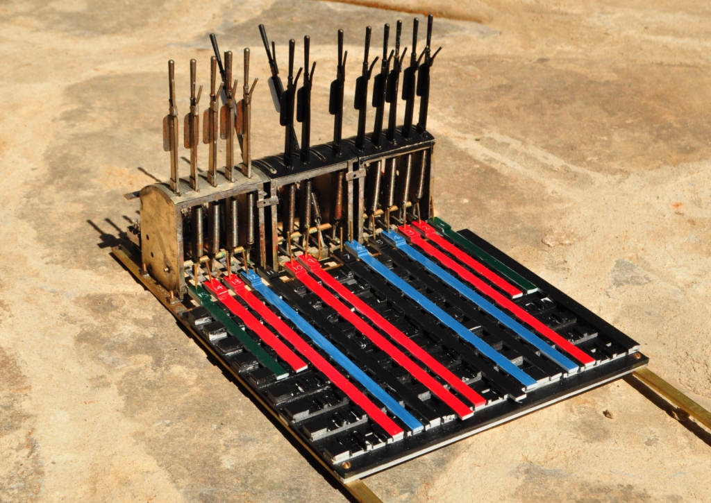
With a lot of help from Keith Norgrove (thanks Keith) the locking design for the lever frame should now be concluded. This is where we are at:
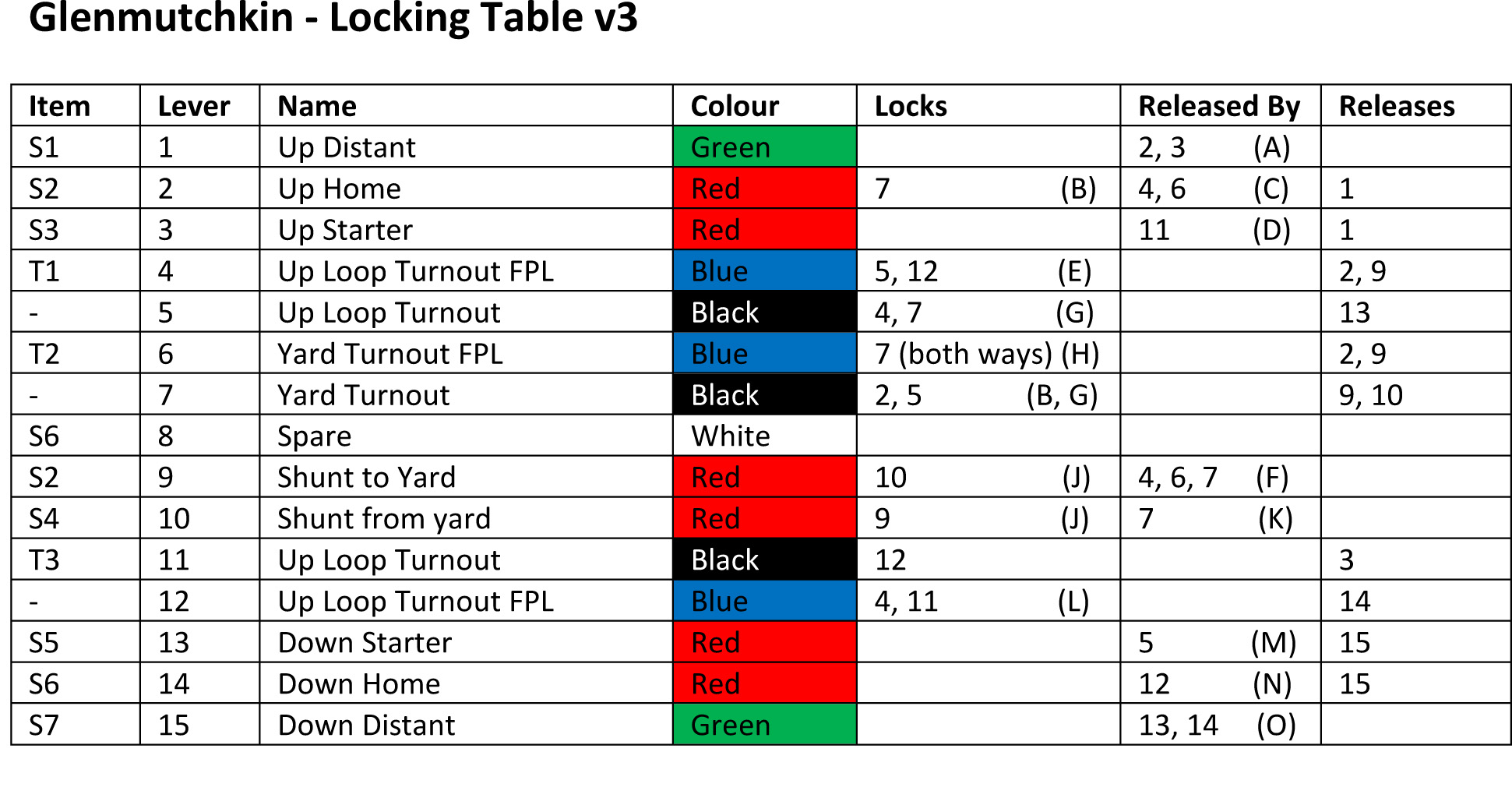
 The lever frame is also ready to receive the beginnings of the locking frame; so guess what i am doing this weekend………..
The Road Overbridge – Part 2
The bridge is coming along and is now close to finished (constructionally).
It has taken a lot of time with plastic filler to get the stones to meet neatly at the corners and also to be coursed sensibly at the corners. Having said this, I am inclined to think it is one of the more important parts of modeling structures and buildings. Cracks or missing sides/ends on a building are just a total no no and even an untrained eye (I am a chartered surveyor so it is worse for me!) spots the error immediately.
This is where we have got too:
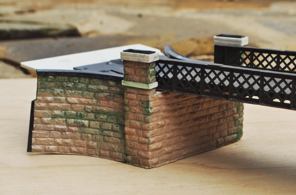
Lots of filler in evidence – but there is still more too do!
The abutments end on
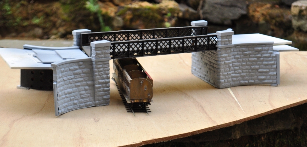
With a carriage to give a sense of scale – the Microrail Drummond All Third has only been on the stocks for 15 years………..
I am not happy with the string course at the moment, it sticks out too abruptly and possibly the same for the copings to the top of the parapet – so more filing and sanding………….
However, it does look like a bridge and I doubt the civils guys will condemn it!
The Road Overbridge – Part 1
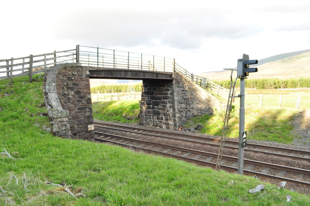
The bridge is in fact modelled on the one at Killiecrankie, but there were very similar ones at The Mound, Kyle of Lochalsh, Keith amongst others. Heres a picture of the Kyle one:
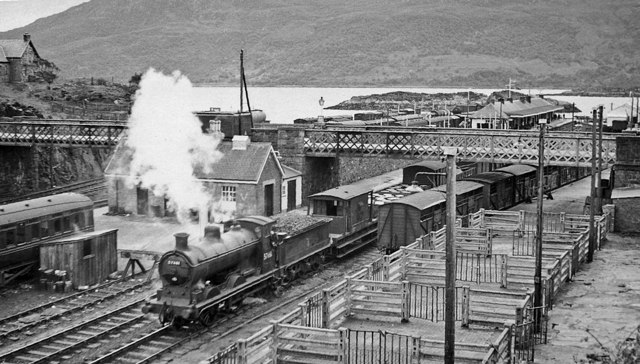
Copyright by Ben Brookshank and reproduced under a creative commons licence
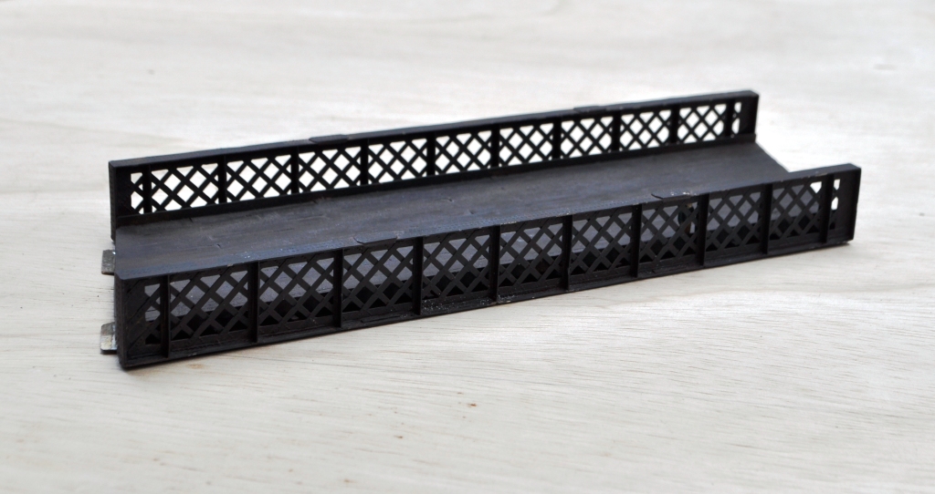
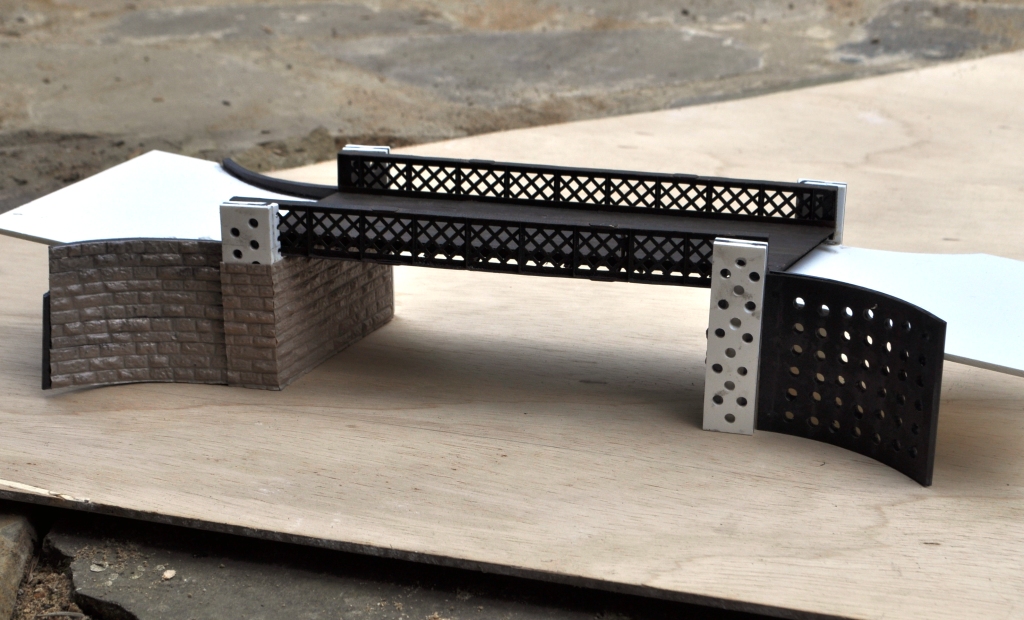
The advantage of using the Killiecrankie bridge is that I had previously modelled one for a layout of this station and whilst the abutments are still firmly attached to some mothballed boards, the deck could be reused. The deck has a nice skew to it to make it a bit more interesting and utilises lattice girders; which few seem to bother modelling. This is what it looks like:
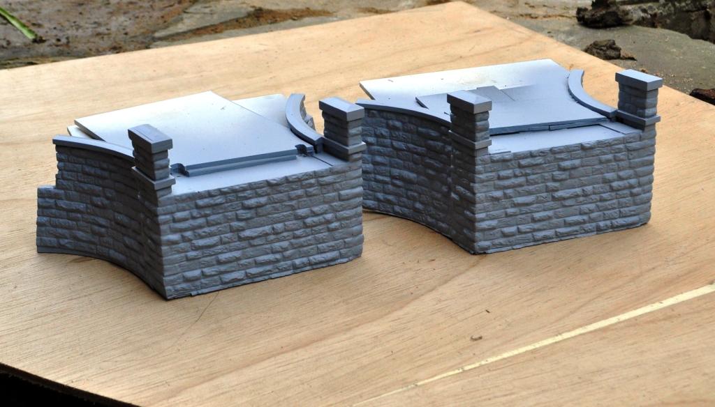
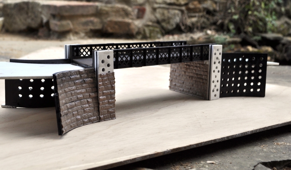
In terms of abutments, most Highland (and indeed this is common to most scottish lines) had bridges with curved wingwalls swept back from the face of the abutment. To give the layout some locational character, this was something I wished to produce. This is where we are at presently with the abutments: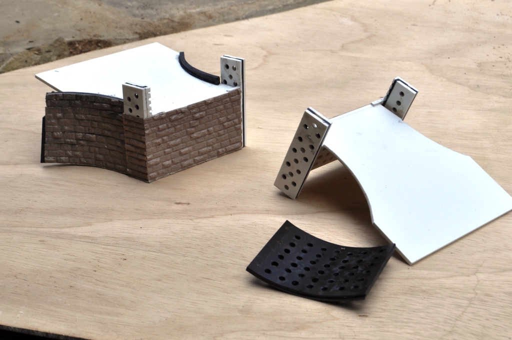 Typically, the random or dressed stone ranges from Wills are my favoured mediums but seeing Andy G making a good go utilising Slaters 7mm coursed stone I thought I would have an experiement with this. This is because many of the later bridges on the Highland used the same coarsely dressed stone; like this one at Dalwhinnie:
And these show the bridge deck on the abutments as they stand:
_________________ Mark Tatlow
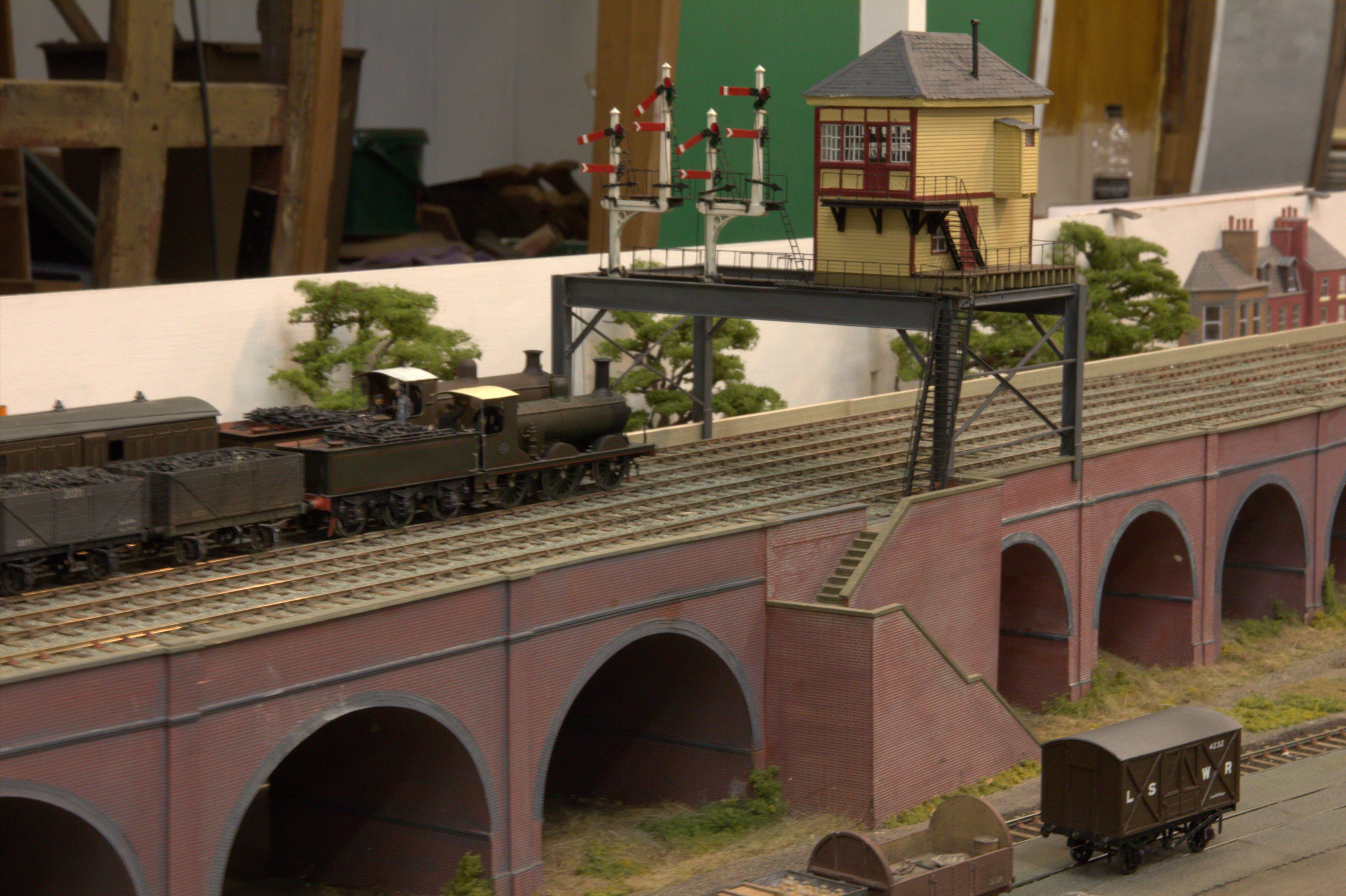
Glenmutchkin Part 5: Signalling
Whilst they are not without their frustrations (they are delicate for example), I was slightly surprised to have enjoyed building and using the signals as much as I did. Therefore, Glenmutchkins will going a bit more large on signals.
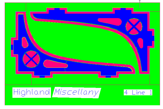
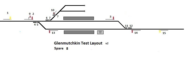
I am assisted in that the Highland seemed to follow the trend of the pre-group companies and be fairly lavish with their signals. Taking significant cues from my sources of inspiration, Wick and Kyle of Lochalsh, this is where I have got to with a signalling plan.
As can be seen, there is a fair amount to this as I have assumed that there is a junction off scene that is signalled from the station cabin (although this is still under review) and not only is the yard signalled onto the running line but both the run around loops and the shed are both signalled. It looks like this will be a 45 lever frame, so there is a fair amount to do……………
A particular signal to note is the one with arms 17,18 & 19 on it. This is a repeater for arms 15 & 16 so directs locos coming off the yard where they are to go to. This exact same situation existed at Kyle and in addition to being a surprising duplication between the two signals the former is that the signal is situated well up on the bank and faces fairly firmly towards the shed, not the running lines. I do not presently have a photograph that is free of copyright to illustrate this but there are lots in the various text books; try The Highland in LMS Days or LMS Engine Sheds.
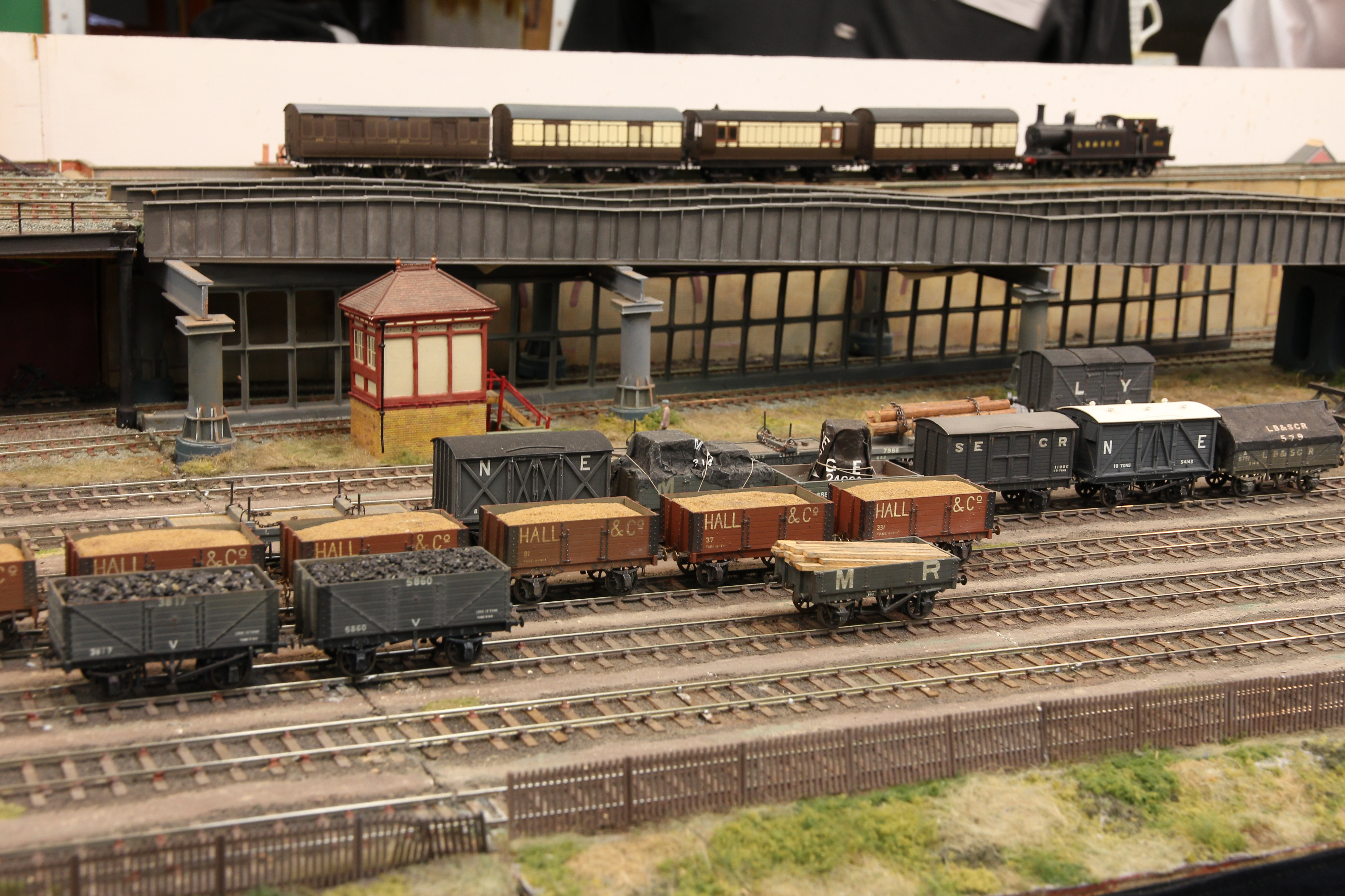
Glenmutchkin Part 4 – Inspiration
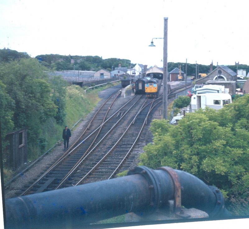
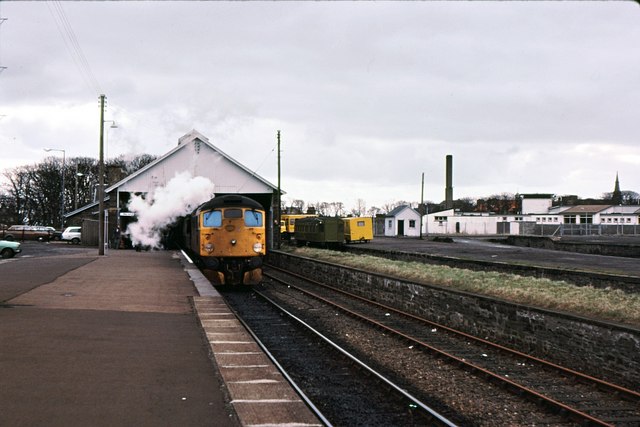
Glenmutchkin’s main source of inspiration is Wick or its slightly more slimline cousin, Thurso. These are very similar in layout except for their MPD’s; where Wick’s was quite a lot larger.
An overall view of Thurso in the 1970’s, with thank to Richard Oaks
Wick in 1983; photograph by Peter Whatley with Creatives Commons Licence
However, rather than a facsimile of either (hey Ben Alder/Richard Oaks has nabbed that idea anyway!), I am proposing to use the same arrangement of MPD as at Kyle of Lochalsh’s shed area, with the access road leading to a turntable and then the shed roads coming back off this. Due to the way that the layout will sit in its home, I have had to do a mirror of the shed at Kyle but otherwise it will be the same.
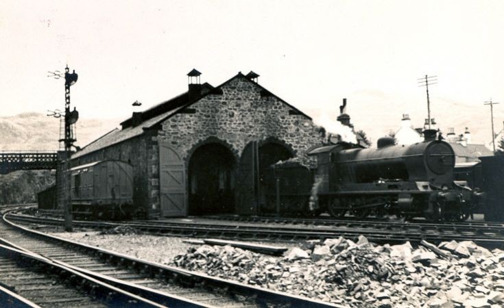
A rather fab photo of Kyle shed with a superheater goods (which were the mainstay of the line from about 1930 through to just after the war) on shed. It is also a fine view of the signal here – one that I wish to model. Photo with thanks to Jim Payne and available at www.throughtheireyes2.co.uk
All of the lines to the west coast of Scotland; both built by the Highland or any of its rival companies or projected come late in the 19th century – partly as a result of Prof Aytoun’s story that I have paraphrased in part 2. Wick and Thurso however were built rather before this and are stylistically rather different as a result. The main differences are the way that the platforms were arranged and the use of a stone built station building/train shed. However, having decided that the Glenmutchkin was much earlier than this, I felt that I could assume that the terminus was built before any of the other lines to the west coast were achieved and thus use the older style of station. In practise I have done so because I wish to model the overall roof – probably the building at Wick as its screen to the end of the train shed is very attractive.
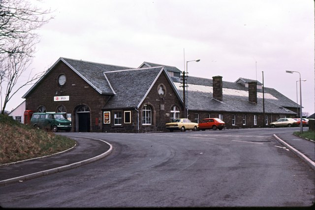
Photo of the road side of the main station building at Wick (that at Thurso is a bit smaller). Copyright held by Peter Whatley and reproduced under a Creative Commons Licence.
Another feature of Kyle that I will take is the overbridge splitting the station from the shed area. Being the son of a bridge engineer, I guess I need to get some proper civils into the model and the latticework is quite attractive. I will go for a single span bridge, rather than the twin span seen here at Kyle.
Copyright held by Ben Brookshank and reproduced under a Creative Commons Licence
Those cattle pens will appear at some point too!
Glenmutchkin: Part 3 – Era
Whilst I seem to be known in the electronic ether for my 1970’s modelling, this is not really my main interest.
Many years ago, I set my main era as the early years of the LMS. Whilst I do quite like some of the LMS standard classes, it was really the sight of the Edwardian and Victorian locomotives of the Highland in the lined red pulling a rake of fully lined coaches that seduced me. After all; who could resist something like this:
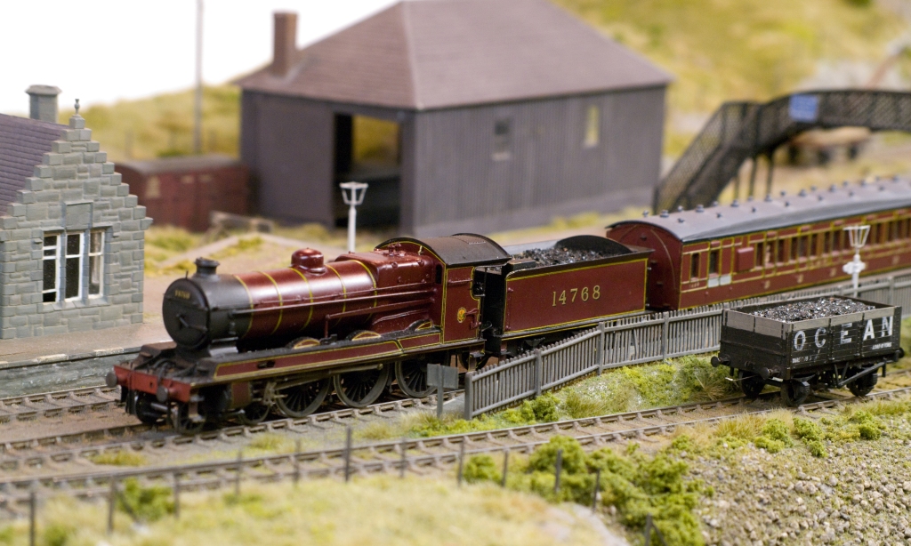
or this:
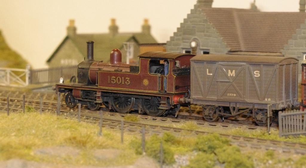
Its peculiar; I would think that the 1920’s is the least modelled era after about the 1880s? Think about it, when did you last see a model from this era?
My regret for this period though is the loss of the red oxide painted goods stock. The Highland often (apparently at random as to when they would and when not) pick out the ironwork of these in black and again I am drawn to the fusion of colour that occurred as a result. To get over this contradiction; I model in about 1925/1926. Much of the passenger stock and locos had by then been repainted in the new corporate LMS colours but at least some of the good stock remained in the old pregroup livery.
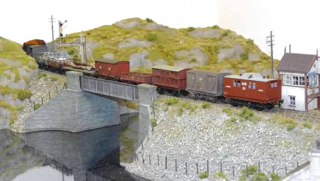
with thanks to Ray Nolton for two of the pictures
First Signal for Glenmutchkin
I have managed to finished (for now anyway, see below) the first bracket signal for the layout. So here are some pictures:


One error I did manage to include in the build was to make the holes in the balance levers, the crank elbows and the signal arms a tad to big for the operating wire I used. I used 12 gauge guitar wire and the slop that this creates in a 0.5mm hole is rather too much. 0.5mm drills were the smallest I had when I built this so I have invested in a stack of 0.4mm and 0.3mm from drillsuk (on ebay). Next time I will try these really small drills because the thin operating wire does look the part.
The effect of this is to allow the arms to slop too much and they will not be capable of being made to bounce properly. This signal will be in a cutting of the proposed layout, so I will have to replace the wire with something a bit thicker to overcome this.
You live and learn!
I am also having a bit of trouble with the MERG servo drivers; I may be cooking them with my power supply so this needs a bit of work too
