Blog Archives

Control Freak
I have been back onto the layout of late, with a view to get the first wheel turning on it before too long. That means attacking the electrickery things, beginning with the control panel.
I made a start on this by drawing up a diagrammatic representation in MS Paint and then using this to get one of the online firms (Vistaprint) to print me up a poster board to form the basis of the control panel. I am not sure I chose the right material as it turned up on a light weight foam board and I had to mount a sheet of aluminium behind for it to be stiff enough to be useable. But it did look pretty smart I thought………….
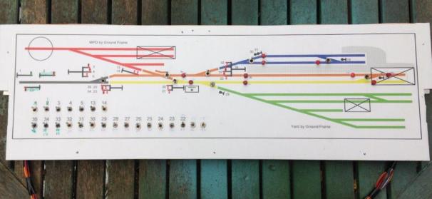
The control panel deals with all of the signals and turnouts that the cabin will have controlled, with local ground frames (which will be located on the boards locally) to be used to control the goods yard and the MPD. The latter will be arranged such that it can be located either to the front or the rear, to allow some flexibility in operation.
I have got to the point where the full extent of switches have been wired in and I am just completing the jumper leads. I took a lot of care to plan the wiring prior to any construction – despite the locos being DCC controlled, there are an awful lot of wires. This is because I have stuck with traditional control for the turnouts and signals. There is further complication as a result of the desire to incorporate some bells and even a block instruments (well maybe, at the moment it is just the wires!). So in all, there are 90 odd wires doing something or another on the layout.
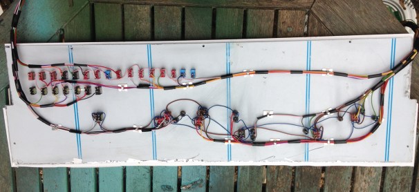
Somewhat in contrast to Portchullin, I have sought to keep the wiring as tidy as possible; everything is neatly collour coded and even labelled (to be fair it was labelled on Portchullin, but in a non colourfast ink………..!). I am hoping that this will make the wiring easier to debug at the start of the matter and repair if it does get damaged.
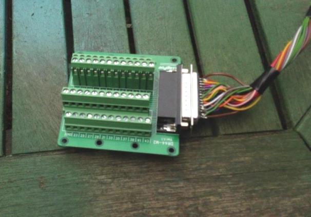
I am proposing to use a variety of connectors between boards and to the control panel, including this rather nifty varient of the D-sub range that is wired directly onot a cheeseblock wireless connector. Available to a variety of types from ebay including from this seller.

Going Long – Part 2; Bogies Most of the Way There
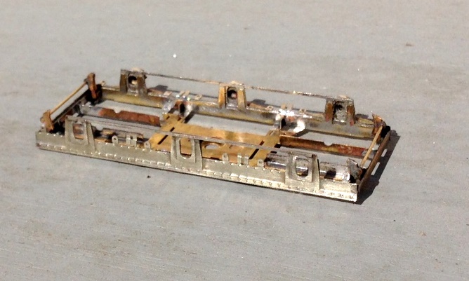
As originally conceived by Barry Fleming, the floor was to be permanently attached to the body sides and so too were the lower roof sections. The only access internally, therefore, was to be the clerestory roof/sides to the centre of the roof. In addition to being very restricted, over time there was a little distortion of this section relative to the more chunky body, such that it has developed a bit of a bow – see the final picture of this post. I have been building a few coaches of late and have arrived at the view that it is desirable to have the underframe detachable from the body and if at all possible the roof too. In this case, I am going to give up making the roof detachable but will keep the underframe as a separate piece and arrange for the floor and interior to slide out of the body. In order to provide a mount onto which I can secure the securing bolts to retain the two parts together, I came up with a metal bracket that has been glued into the coach vestibule where it is hidden as below.
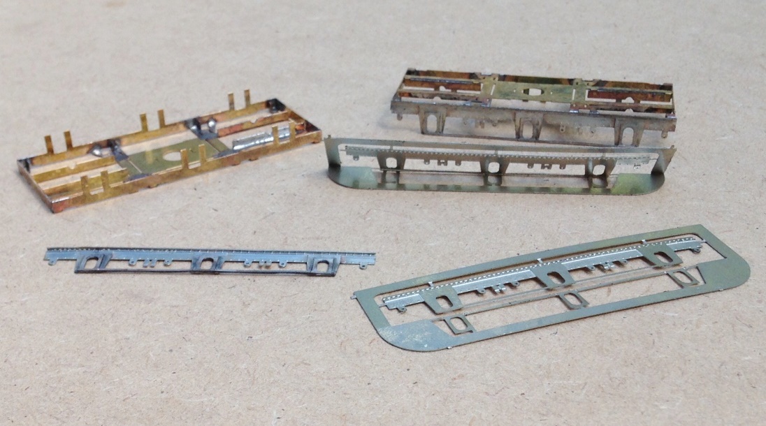
With this completed, I turned my attention to the bogies. These are based around the Bill Bedford sprung bogies, now supplied by Eileen’s Emporium – there is one with the right dimensions for the ECJS bogie. These are only the sprung assembly and offer no detail of the real bogie at all and these were quite characteristic riveted plates. I am not aware of any offerings from the trade for these, so I have had to create my own – out comes the CAD machine again! Actually, they are quite easy to draft and there was a fairly good drawing available. As with some of my other etch designs, I have used folding jigs to ensure that the layers come together correctly without bother. In the photo below you can see the basic Bill Bedford sprung frame on the left upper, the basic etch to the bottom right and the finished side with the layers laminated to the bottom left.
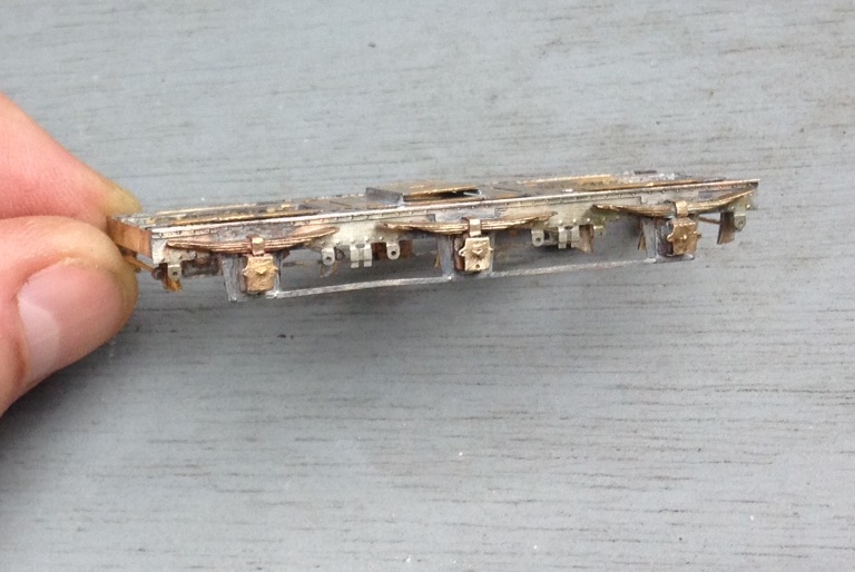
And this is a close up of the bogie sides fitted and some of the brake hangers fitted.
After searching around, I decided that the best means of making the axleboxes and springs was to use the Drummond pattern axlebox/spring assembly from Lochgorm Models. These are really nice but the springs are too long such that the hangers are a bit far out for the six wheeled bogie – hence I formed a hanger point as part of the etching, which you can see yet to be folded down on the above picture. The intention will be to insert a brass rod through the hole in this and to then mount small washers on it to give the impression of the springs. A similar rechnique is used on some of the 5522 models bogies and is quite effective. With this representing the hangers, those to the casting could be cut away.
The axleboxes are rather nice, as you will see, and are of cast brass. The bad news about this is that they are really hard and quite a lot of work is required with a dental burr to open out the rear to be free of the bearing.
And a look at both bogies together, now with the bearing spring hangers in place along with the brake hangers and rods.

A key feature of these bogies was the transverse bolster springs, which are apparent between the axle spacings. I did come up with a scheme to form these but they have not proved to work. I think I can cut and paste a pair of the bolsters from what I have produced (ie half the number I need) so I am going to have another bash and if not, it is back to the drawing board! So whilst I work out how I am going to wrestle with this (I do have some ideas, I just need a bit of time to implement them!), lets at least admire what the coach looks like in its semi-complete state:
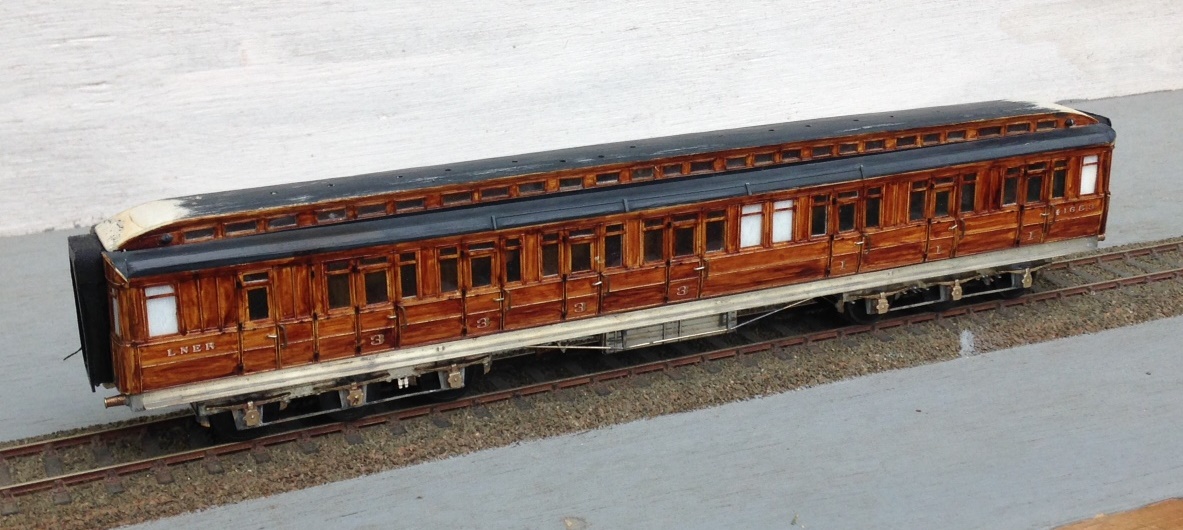
There are other things to do with the coach; the centre part of the roof has a bow, there is various detail missing from the underframe, roof and ends yet to go – but it does look the part doesn’t it?
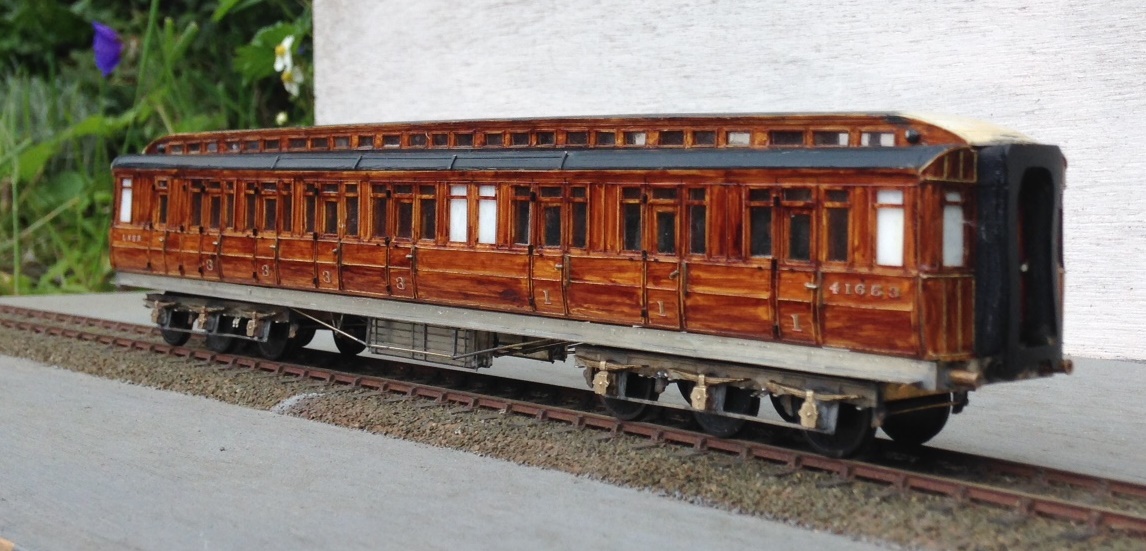
In response to the first part of this blog, Bill Bedford did contact me to help with some prototype details. He was able to tell me that the buffers that I used would only be correct for the brakes and that the udnerframe only had two trusses, not the four that I have modelled. So some corrections will be required……………but first those transverse bolster springs and maybe give the carriage a bit of an outing (I will bring it to Scaleforum for that).
 for Portchullin")
A New Ending (and Beginning) for Portchullin
Don’t worry, it is not as dramatic as all that, I have not burnt it or anything……………………oh hang on a minute, I have – well a bit of it anyway!
One of Portchullin’s quaint little foibles was it did occassionally like to derail trains as they left the fiddleyards; especially the fiddle yard representing Kyle. There were various reasons for this; including some proper cr*p woodwork on my part, the hand shunting that occurred every time a train was turned around, the effects on thermal expansion that was not catered for and, something that I had not seen until recently, a bit of a dogleg at the baseboard joint. Add to this the rather Heath Robinson approach to the legs for the fiddle yard boards, electrical connections and facia support and it was fundementally a b*ggers muddle. So something had to be done and, a mere 8 years after the layout’s first exhibition, it now has!
So with lots of thanks to Tim and Julian at the Electric Loft Ladder Company again, we have a new fiddle yard at the Kyle end and redesigned legs at the Inverness end. The design adopted is an adaptation of the sector plate that was in use before but with a refinement that it uses cassettes for the locations that the loco arrives and departs at. The idea being that these are both storage points at the end of the fiddle yard roads but also the means to move/turn the locos ready for their next duty. This is a development of the system used by Simon Bendall on his layout Elcot Road, but with a rotating sector plate rather than a traverser.

Other halfway novel ideas are the use of the tray below the traverser as a storage tray for stock (and maybe tea!) and the projection of the sector plate beyond the end of the fixed board to make the ensemble smaller to transport. The facia also folds up rather niftily as well – photos of this will follow once I have taken them!
The new fiddle yard has not yet been tested but will very shortly get its chance to prove if it is a good’n. Portchullin will be out at the Barnstaple MRC’s show in Bear Street, Barnstaple – you can find details here. If you are in North Devon at the weekend, stop by and say hellow?

New Shoes for Some Old Friends
Over the last few weeks, I have been revisiting a number of model coaches that I have built in the past, typically quite some time in the past as most of these have been around since either my teens or twentys!
Over the years techniques have changed and I undoubtedly would not build most of them in the manner that I originally built them if I was confronted with doing them again. Having said this, on the whole my handiwork – especially in respect of the painting and lining was really quite good. I seem to have lost my lining mojo in particular, so I am not sure I could line as well as this now. This is something that I really must get to grips with this, as I still have a lot to do!
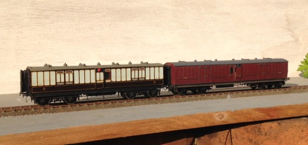
a pair of full brakes, the one to the left is a West Coast Joint Stock (from a London Road Models kit) and that to the right is straight LNWR (from a Microrail kit)
But the biggest area of difficulty with the coaches is that the bogies were generally formed around beam compensation units. These are OK for a couple of coaches behind a branch train but they impart far too much friction for a full main-line train as I aspire too. This is impossible to overcome whilst retaining the compensation units, the bar is the cause of the problem and it has to go!
To overcome this, Bill Bedford sprung boiges are being retro-fitting to all of my existing stock. These rely on separate hornblocks that secure a pin-point bearing in them – so rolling resistance is significantly reduced. The hornblocks are held in place by way of guitar wire and the effect is that they glide around the trackwork. They thus give the impression of weight and inertia that is much better than compensation (it is possible to get compensation that does not use the rocking beams that are the cause of the fritchion I am complaining about).
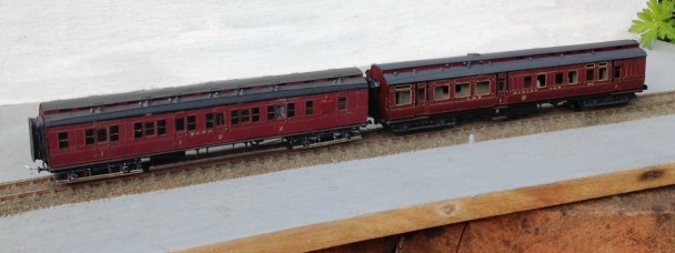
A Midland & North British luggage composite (from a PC Models kit) and a LMS (ex Midland) dining car (from a 5522 Models kit).
The Bill Bedford units are only an inner bogie and they still need to have some form of detailing on the outside. Some of these have entirely cosmetic outers, either of plastic or white metal but the two Midland coaches and the Highland TPO have something slightly different. On these, I utilised the original etched bogie sides and laminated them onto the Bill Bedford inners. This is very successful as it improves the Bill Bedfords notably by making them a lot stiffer and you get the crispness of the etching process.
This is one of my fathers, so I can’t claim credit for anything but the bogies. A Highland Railway TP (fully scratchbuilt). Obviously, no painting has as yet been done, so it does rather look like a ganster with gold teeth!
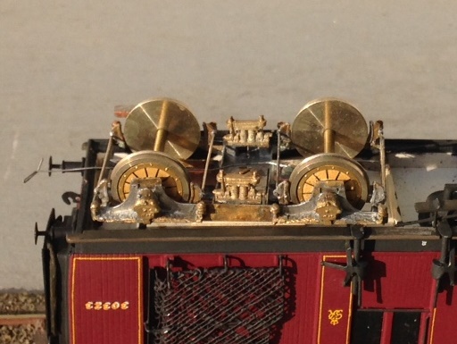
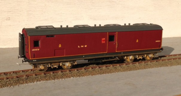
It is rather challenging to see how the Bed Bedford sprining unit sites inside the outer skins (from a Lochgorm kit) – so I will write up the process in a future blog – but this is what it looks like from the outside.
If, by the way you fancy some Fox Pressed Steel bogies that are neatly sprung and look the part – and almost all pre-group modellers ought to – keep watching the space. Subject to a test build or two, there will shortly be one available on the market.
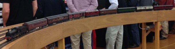
To test them, I took them and a few other coaches to ExpoEM to use their test track. Here we see a Barney with eight on – albeit a rather od mix for the train and there is a fair amount of painting and lining still to be done.
And to prove that they really do work and also to allow you to see how they glide, a quick youtube video: https://www.youtube.com/watch?v=6D7a_cWwGhg&feature=youtu.be

Gresley Buffet – Part 4 Finished!
…..but, before it was counted as finished, it needs to be doing the job it was designed for – buffeting. And that means it needs to be populated with people.
Regrettably few modellers, even finescale modellers, actually put people in thier coaches (and sometimes in contrast to platforms which are stuffed with them!). This is a shame as they do make a difference to even a fairly casual viewer. At a show recently, a dad and his son who were probably not modellers spotted the people in my coaches instantly. I’ll take that as proof of the point!

As is common with rtr coaches, the seats are moulded in place such that there is no room for the little peoples legs, so some severe amupation is required! In the case of Hornby’s buffet, the seats are also modelled pushed tightly underneath the tables – which has meant that the backs to the seats or the lip of the table also needs to be hacked away a bit. As all of this surgery occurs below the waistline of the coach, it is not visible from outside so your Dr Crippins’ tendancies will go unnoticed!!
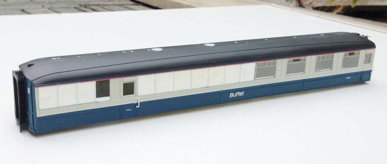
Next up was to paint the exterior where the new plastic was cut in and here I had some problems. I was warned by Brian of Shawplan that I should paint the whole side when I repainted the new sections but I decided not to follow this advice – something I now regret!! So having masked up theadjacent areas and sprayed in only the affected sections i found that the grey that Hornby used was notably bluer than that provided by Precision Paints. The first attempt at repainting had the colours sticking out like a sore thumb and even on the second attempt, with a dab of blue in the mix is not perfect but is just ok underneath the grime. So, if you are proposing to do follow this build follow Brian’s advice, not mine!
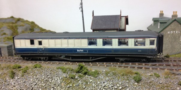
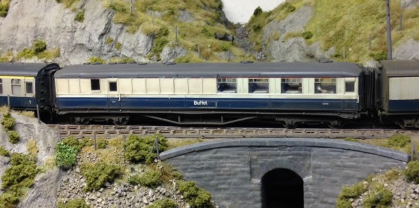
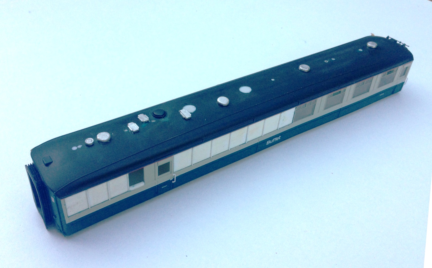
Once a couple of new windows were cut into the reshaped windows in the kitchen area of the buffet car, it was necessary to weather the vehicle. These buffet cars were notorious for being really tatty by the 1970’s; partly because the paint supposedly was prone to debonding from the underlying teak but also because the automatic washers were not good at getting into the corners of the panelling. After an overall spray of dirt to tone down the colours and another to represent the brake dust and track muck, I used two techniques to represent the weathering on the panelling. The first was to spray the whole coach with a mist and once it had started to dry a stiff artist’s brush was dipped in thinners was used to remove the bulk of the paint. The areas that it does not come away from are the nooks and crannies around the panelling; the same areas that would have retained the dirt in the real things. I to find, however, that the margine between where the paint has been removed and not can be a bit stark, so I used a second technique to both hramonise this and also acceptuate the effect. Using a heavily thinned dirty black paint, run a brush over the whole of the sides – the paint runs to the corners and achieves the same effect. It pays to be brave with this as the wetting effect of the thinners makes this initially look much darker until the thinners have dried off.
And this is what the finished article looks like………
So thanks Hornby for supplying the model in the first place and the inspiration to do some plastic surgery. Whilst this write up may have lasted some months, actually this was quite a quick conversion – the basic surgery on the side was only 4 hours – so why not have a go?
A Quiet Day at Portchullin…………
Although it may be that there is a train in the yard as the shunt signal is off…… I suspect it will be one of the class 24s?
Portchullin is just back from a trip to the St Alban’s show and its next outing will be in Telford, for the Diesel & Electric Show on the 20-21 February.
With thanks to David Brandredth and Tim Venton for the cracking photo. Now my fav of the layout!
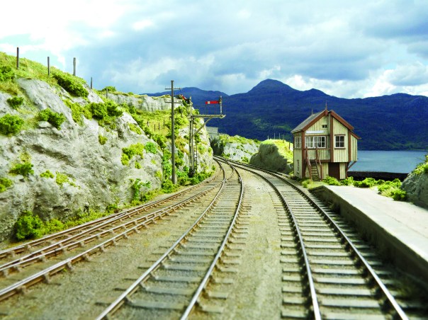
Glenmutckin Shed Area
Glenmutchkin’s shed area is modelled on Kyle of Lochalsh’s (it is a mirror image) and I wanted to capture the typically cramped feel of the inspiration. This is the original OS map for the shed (ie old enough to be outside of copyright).
Key to this is the way that the whole complex centres around the turntable and the first turnout is almost tight against the turntable’s wall as this photo extract shows (notice there is not even a buffer stop on the far side of the well):
The first turnout is, you will see, a tandom and whilst it is not visible in this picture, almost certainly it was interlaced (as the Highland always seemed to always use interlaced turnouts). Well, interlacing gets quite crowded on a tandom turnout, as you can see:
It takes a long time to do all of the sleepers as there are a lot of them but once it is done, it does look rather impressive don’t you think?
_________________
Mark Tatlow
One for the Gorilla – tracklaying progress
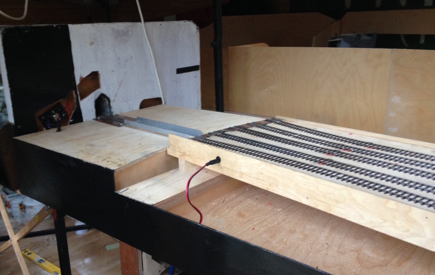
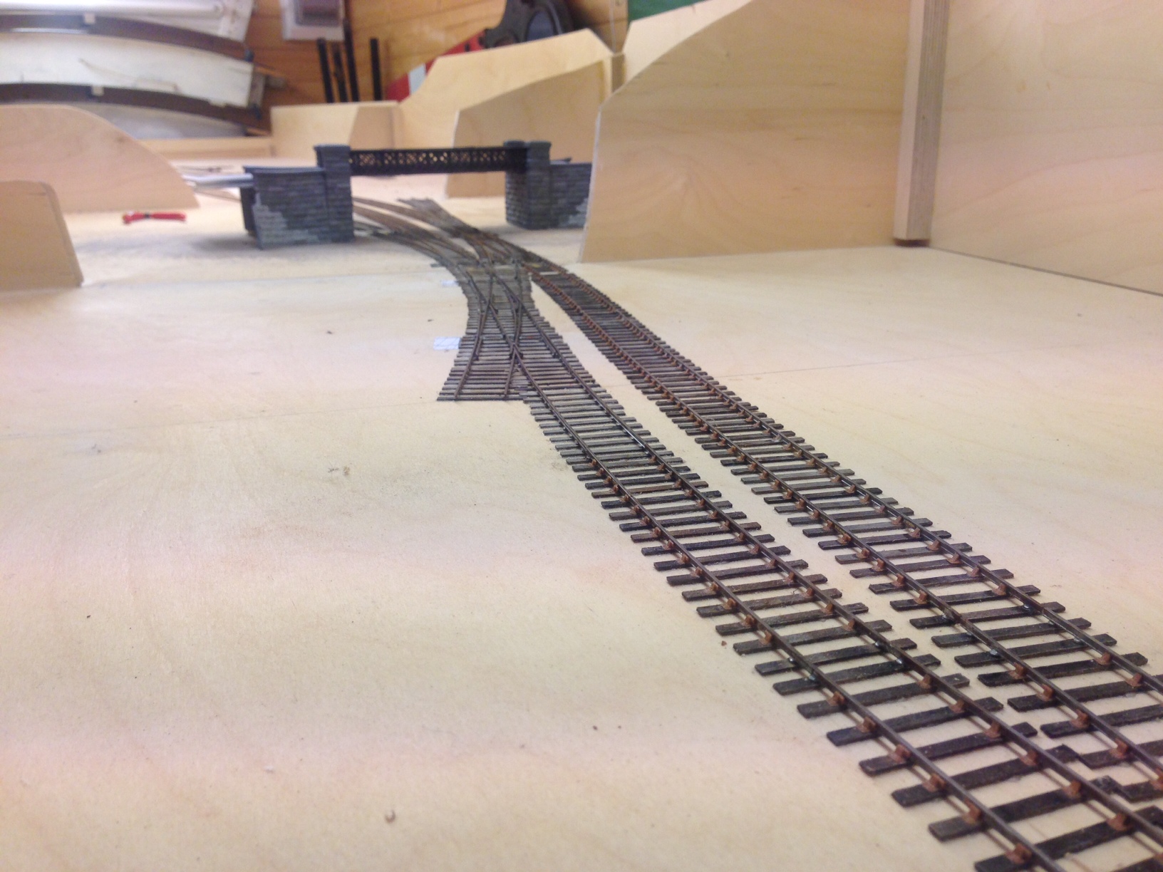
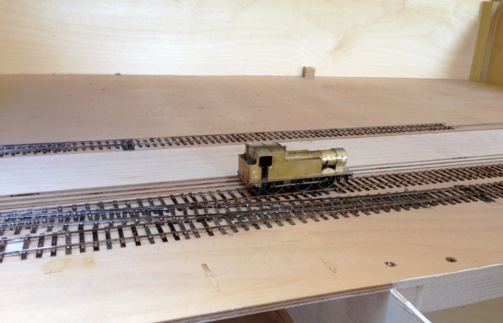
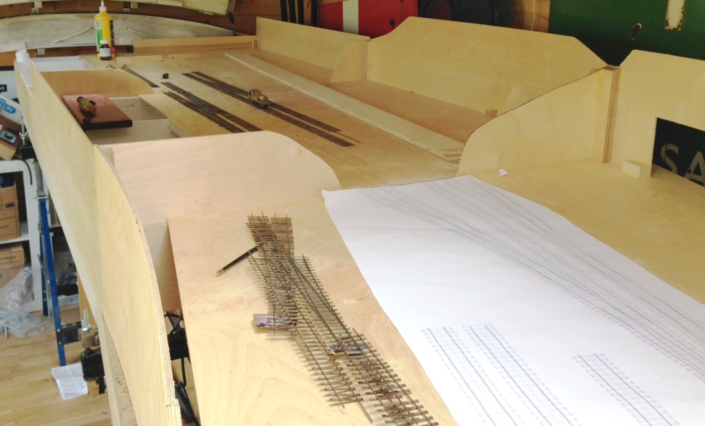
Matters have been progressing with the layout on and off through the summer and a lot more of the track has now been laid. We have both the main line and the full run around loop complete, along with most of the bay and its run around loop too.
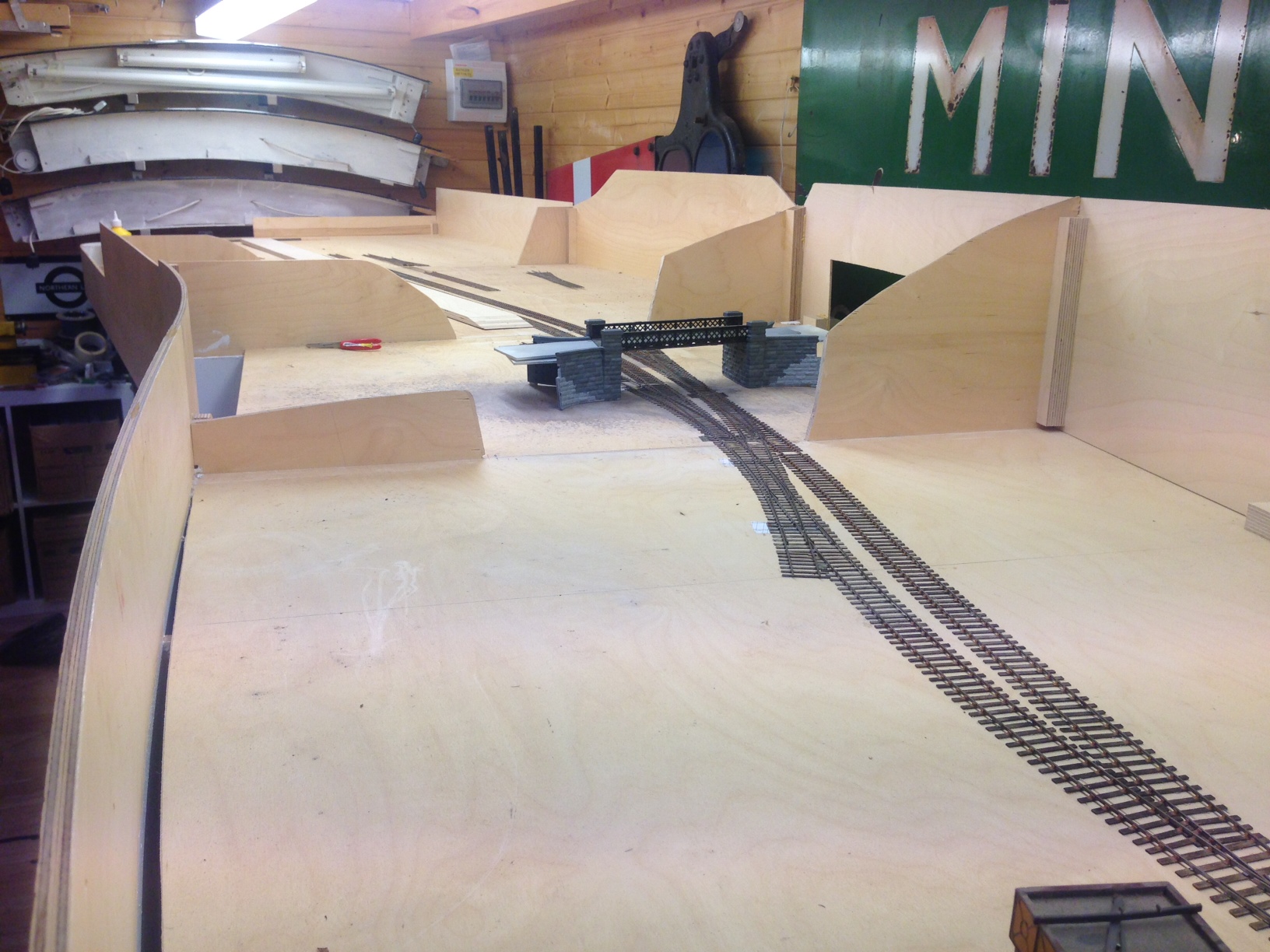
The line diverging in the foreground is going into the shed area, those visible below the bridge go to the bay (left) and yard (right). A signalling trackplan can be found here.
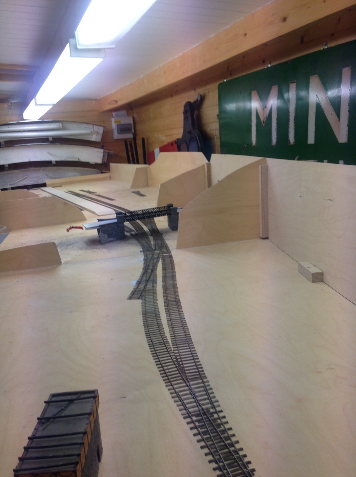
I quite like the sinuousness of the line, which can be seen here/ I have done this in order to give interest to the layoput but it is pretty typical (indeed characteristic) of the lines to the west coast as they wind through the mountainside. I do have in mind some hills to justify this in the finished item.
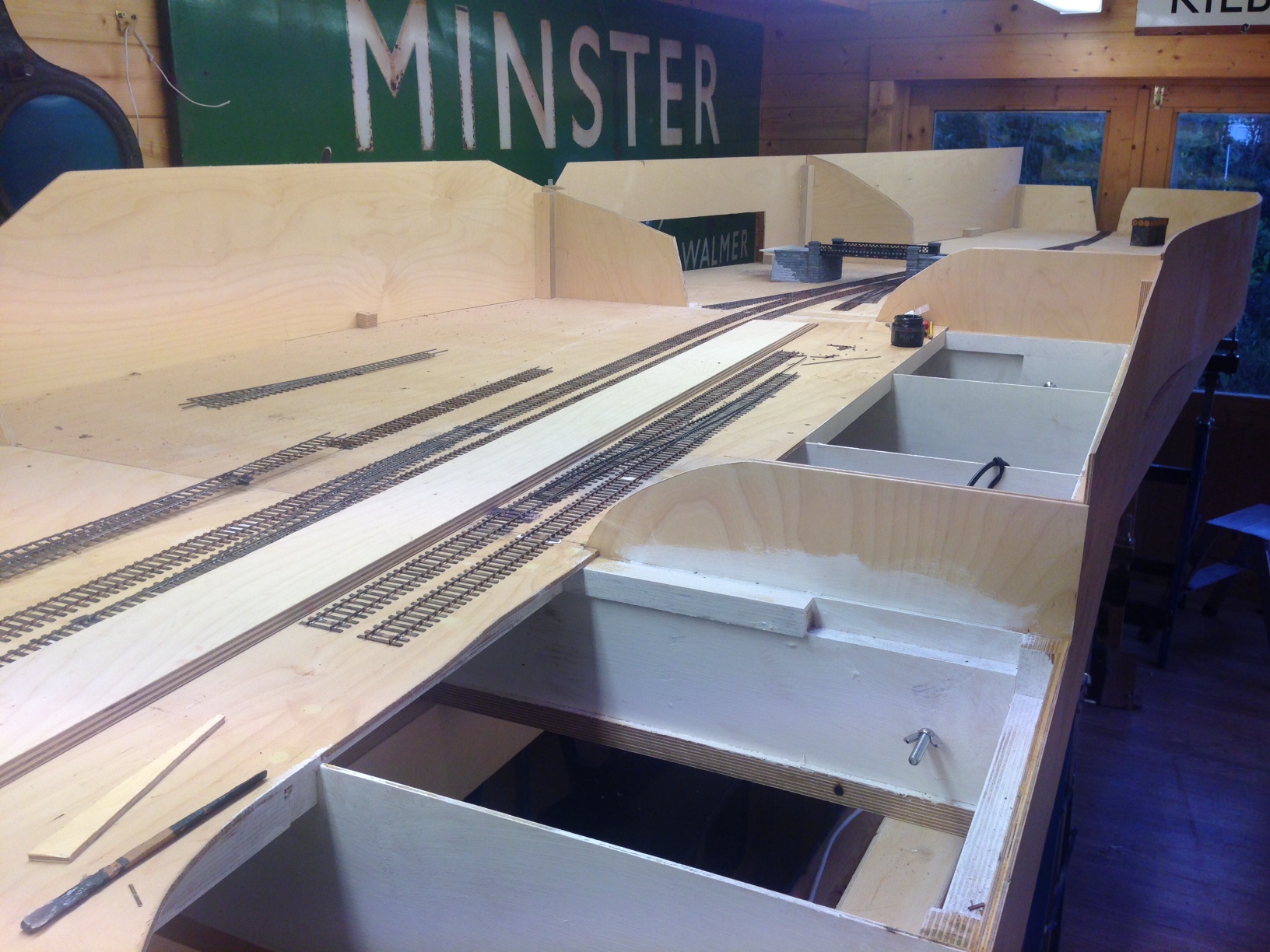
Already there is a sense of magnitude to the station forming, the platform face (which is not all in view in either of these views, comes in at about 7 feet – enough for an eight coach train of pre-grouping coaching stock. Really, its length is defined by the length of the bay – this will become clearer when the train shed appears because the bay has to start clear of this..
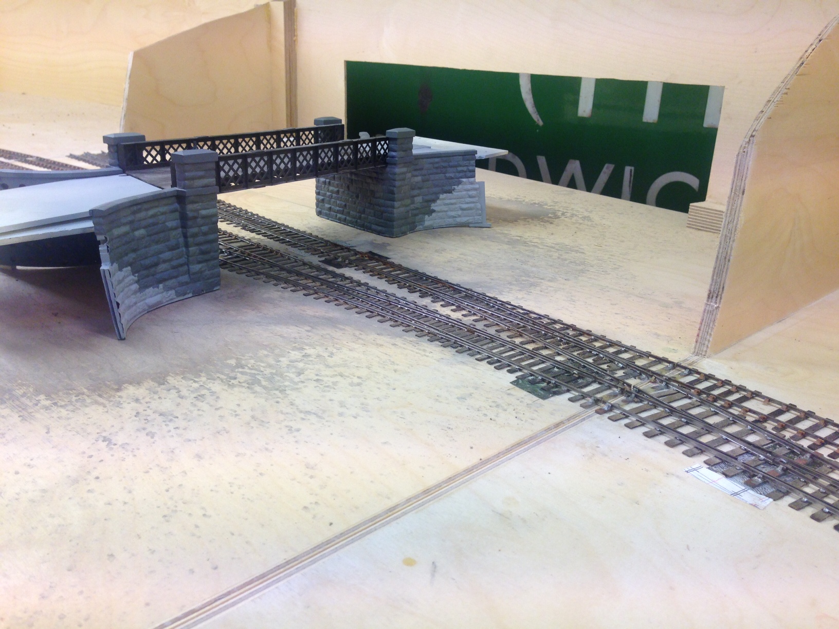
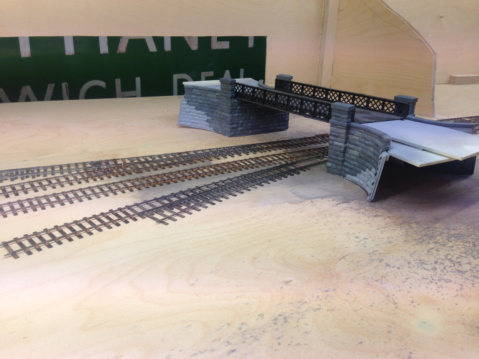
I have also placed into its approximate position the road overbridge that separates the shed from the main station area. The construction of this can be seen in postings here and here. The intention of hte bridge is to act as a scene blocker and thus to compel the watcher to view the layout from more than one location to appreciate it.
The Cruellest Cut – Carrying on with Hornby’s Gresley Buffet
The first task in dealing with ready to run vehicles is to work out how to get into them – not always as easy as it sounds! In this case, this is achieved by slipping finger nails between the sides and the underframe solebars; this releases four catches and the top pops off. The interior then slips out without bother but the glazing is a little more tricky as it is secured with some very gooey glue. Whilst this releases the perspex relatively easily, it was difficult to then remove the remaining glue – I found it best to do this by rolling it with a thumb and accumulating the residue on a scrap of paper but it was a pain getting it all off.
Prior to attacking the model with knife and blade, a sensible precaution is to protected all of the areas that are not to be cut with masking tape, which you will see I have done. This was effective but I did find that I dislodged a filler pipe when I removed it, so perhaps a slip of paper over these would be prudent next time.
Then it was time to get cutting; I varied between using a razor saw and a scalpel to cut a grove by using parallel cuts but in both cases it is important to cut to the waste side of the finished line. I found that it was best to work to an existing bead line, even though when working to the saloon end of the coach the bead was the side of door jamb (this is where I found the knife best and I made sure this was one of the first cuts to be made) so that there was no stress on the thin piece of material. By the time the cutting had been finished the holes were quite big!
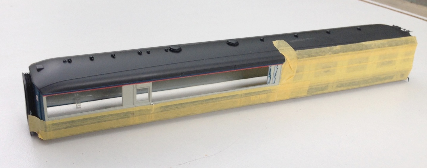
Nearly all the cutting done now; but the last panel to the right did also get cut away
It pays to dress the sides of the opening with care so that they are straight and square as this makes the fitting of the infill pieces much easier. These should be cut fractionally over large and then sanded back by small degrees checking regularly to determine if it fits and taking care to ensure that the square/straight edges are maintained. Once it fits, I let it into the hole and secured with butonone and then left it to cure for a couple of hours so that I did not disturb it when I subsequently fitted the beading. This was formed with 0.2 * 0.2mm microstrip and these needed to be set out with considerable care – aided by the use of venier calipers – to get them regularly spaced and vertical. Even the most minor of inconsistencies detract from the affect.
Replacement panels now in place, including a partial infill of the window by the door
Next up was the removal of the various roof vents and cowls as these too changed. I suspect that these were no consistent across differing vehicles and it is quite difficult to determine what goes where but I was assisted by some photographs from here. Utilising some of the vents salvaged from the Hornby model and also from Comet Models, the latter generally with their shields filed away as the roof views I have have straight flanges as shields – which I formed with brass strip as I though plasticard would be knocked off.
Roof vents in place, based on a photograph of the roof of 9132 at SRPS in the 1970s. I also noted that the alarm gear on the roof was at the other end of the vehicle in comparison to the Hornby model, so this is going to need to be cut away and recreated at the opposite end.
Tracklaying Commences
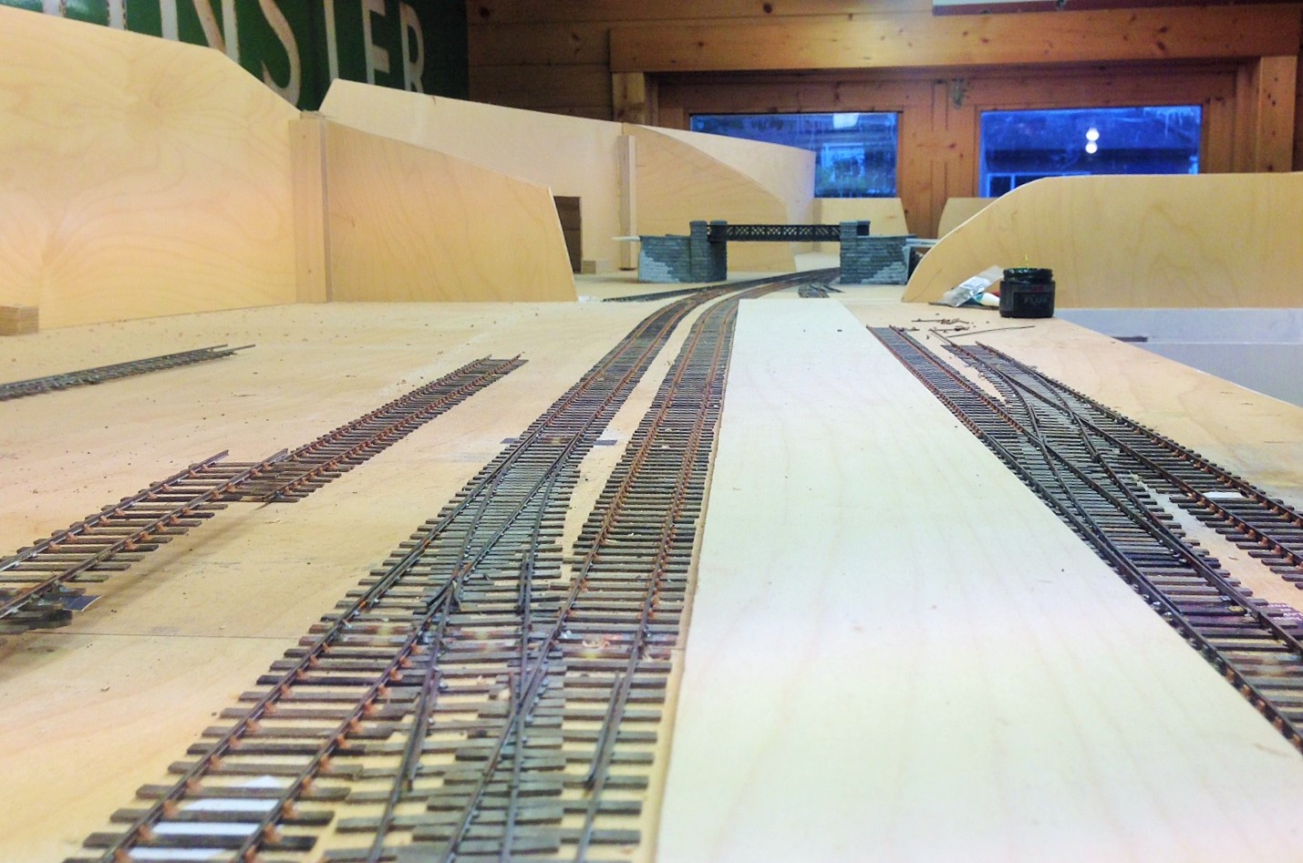
Definite progress was made with Glenmutchkin over the last 10 days, in that the first portions of trackwork have been laid. At last, it is an embryonic layout!
This was started at the two platform faces as in practise this is one of the major setting out points. This is because it is about the only straight bit of track on the layout and also because the platform needs to sit on top of the most substantial baseboard joint on the boards – where the front and back boards abut. The platform will be a separate element of construction and will bolt over the joint, hence hiding it from view.
The scrap tak is seen here sitting in the branch bay. The branch bay platform face is to its full length, the main line platform face still needs to continue for 500mm – into the trainshed which presently can only be imagined!
Now that the first few bits of track have been laid, a sense of scale starts to become apparent. Not for me the “model to the railway boundary only” approach – I am very definitely attempting to portray the railway in its setting.
The other major setting out point for the layout is the link into the engine shed; which is a single slip from the main line and a cross-over from the main run-around loop. The baseboard joint is mid-way through the crossover, so deines this end of the layout.
