Blog Archives

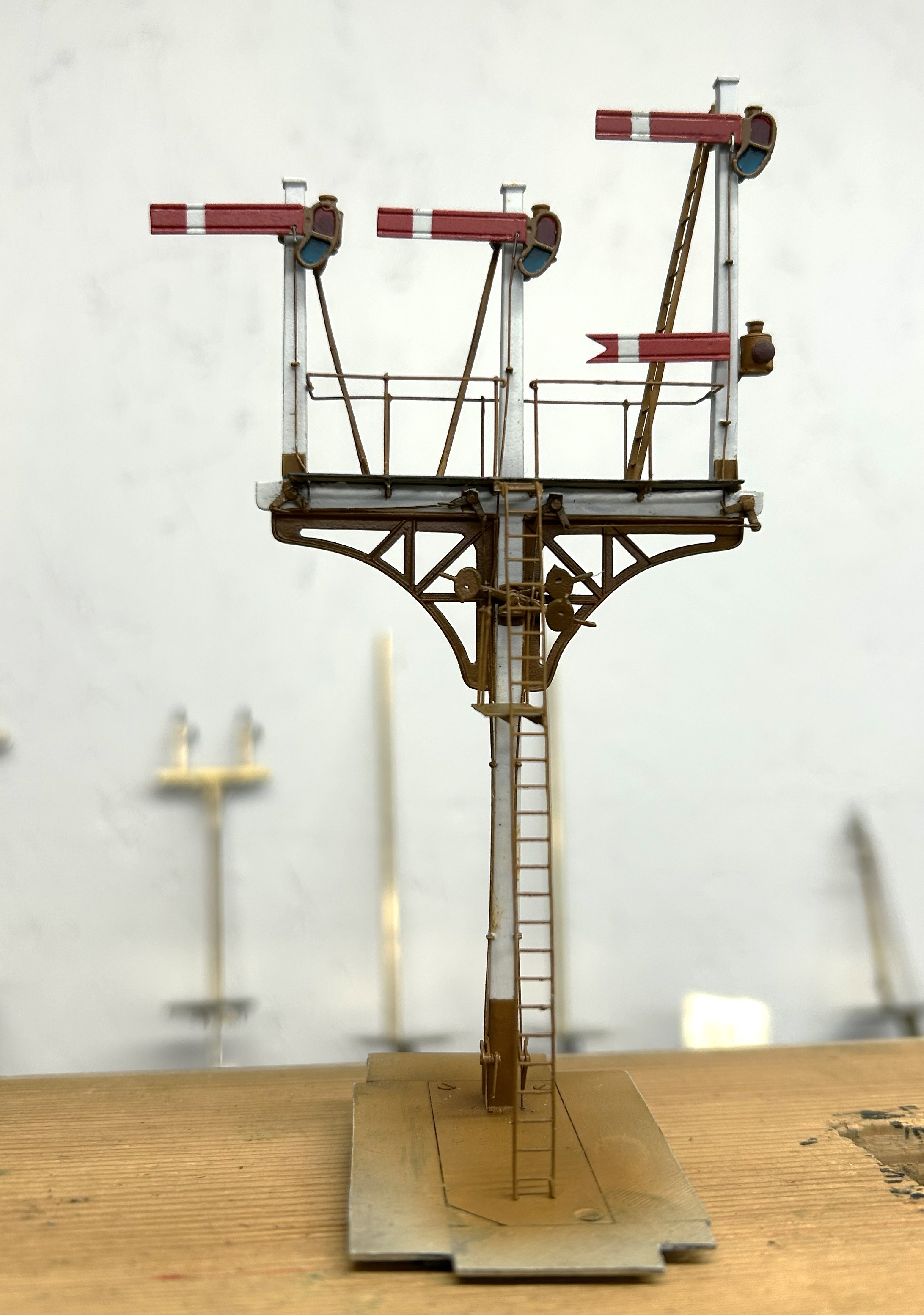
At last, a Finished Signal!
Well, that took a while longer to make than I had hoped! Not least because it is not the only signal I am working on at the moment.
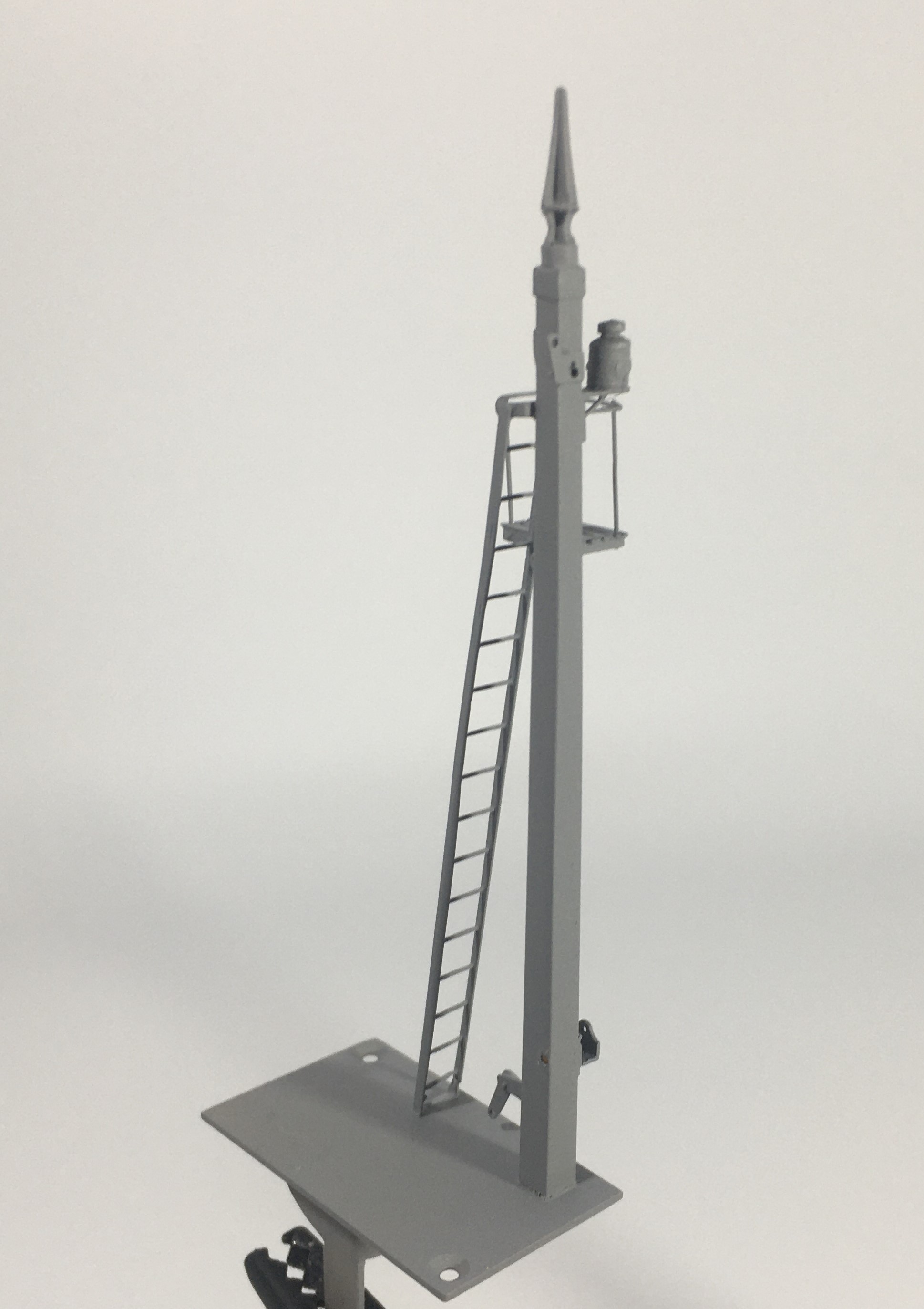
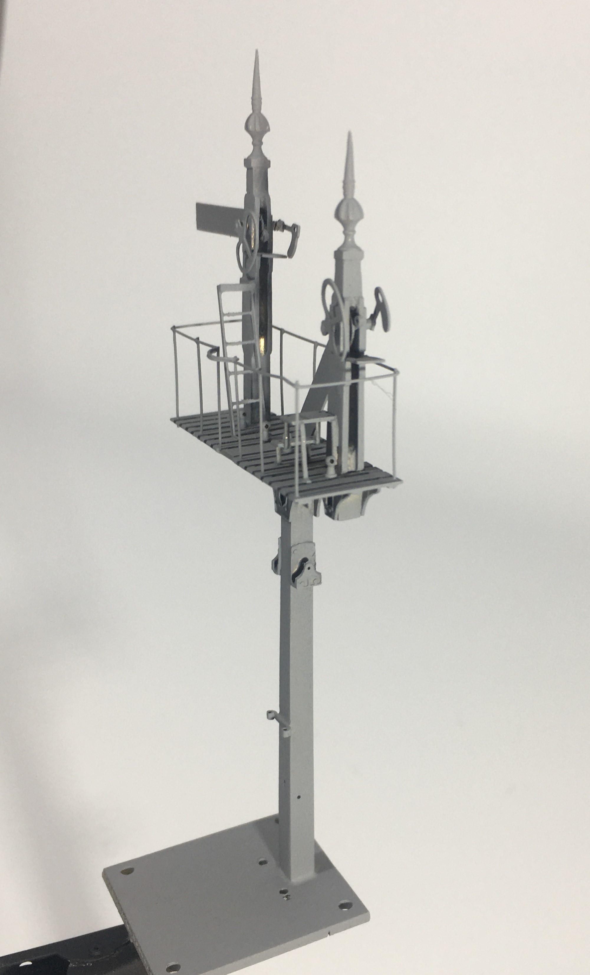
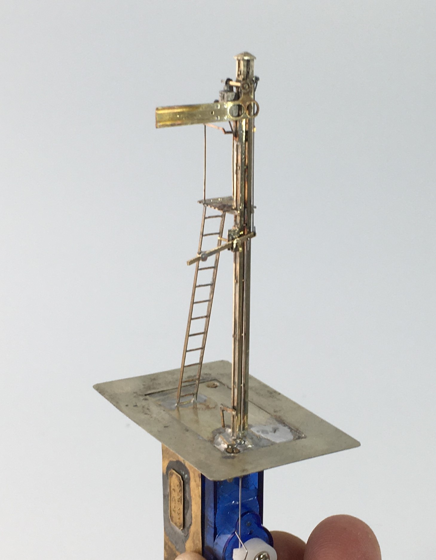
Although the drawing did not show a landing in front of the balance weights, i felt that it was likely one would be provided given that these need maintenance at times. Hence this was formed from some L section and an etched slats and provides a useful point to secure the ladder too.
The issue with signals with dolls is that each doll is in effect its own signal; it has a ladder, arm and lamp assembly. But worse than this is that it is also necessary to get the movement to transfer over to the doll so there is even more than a seperate signal per doll. There are a number of ways the prototype used to get the movement to transfer and in this case the signal uses L shaped elbows. Sadly these are more challenging to make as there are more working components and to be prototypical they out to be little more than a couple of mm in size.
A key trick in making signals is to spray paint as much of the signal as possible. Because the components are generally fine any excess thickness of paint will quickly make the modelling crude. As a result of this, I now generally try to make the ladders detachable. In this case there is a rod attached to the top of the doll that a tube at the top of the ladder slips over, with prongs at the base.
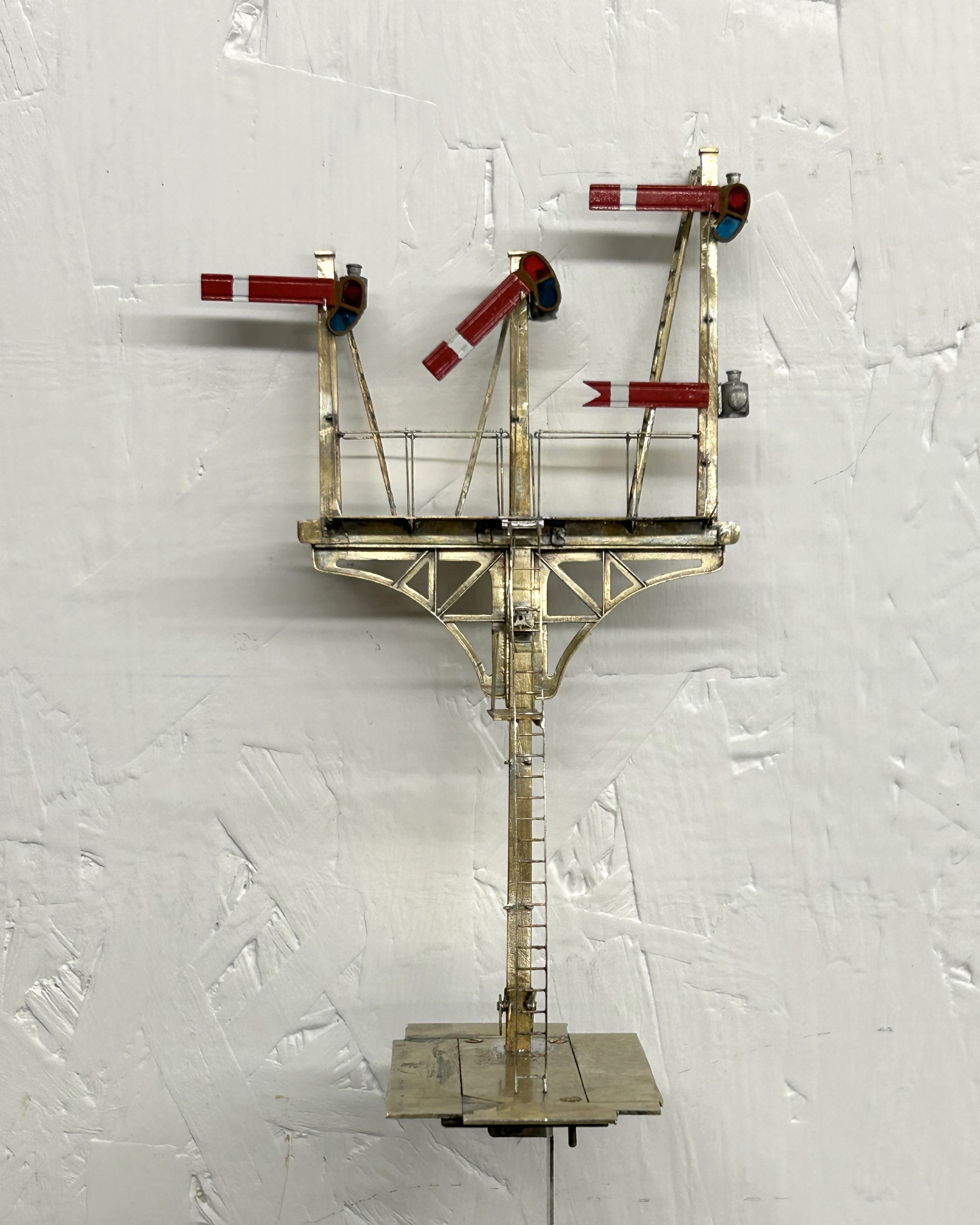
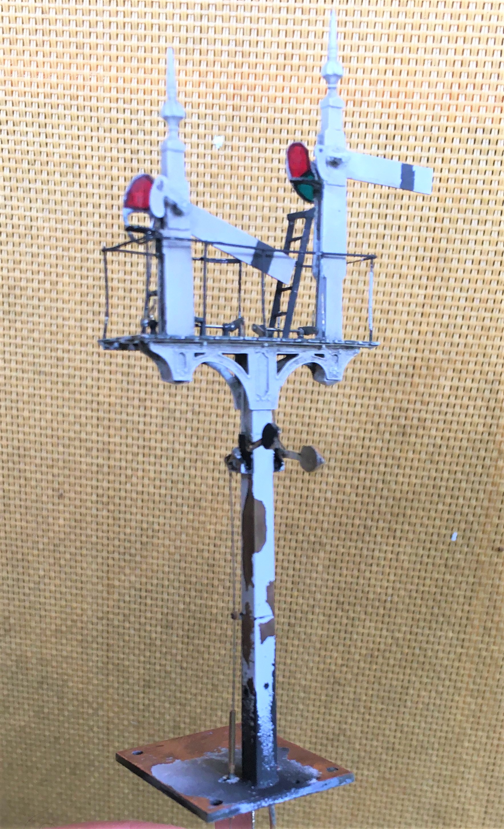
So here it is a finished (except for a tie rod which I fortgot to paint so is to be fitted shortly).
And as is de rigeur for a blog post on the building of signals, here is a video of it in operation.
")
More Seasons Greetings (and Signals)
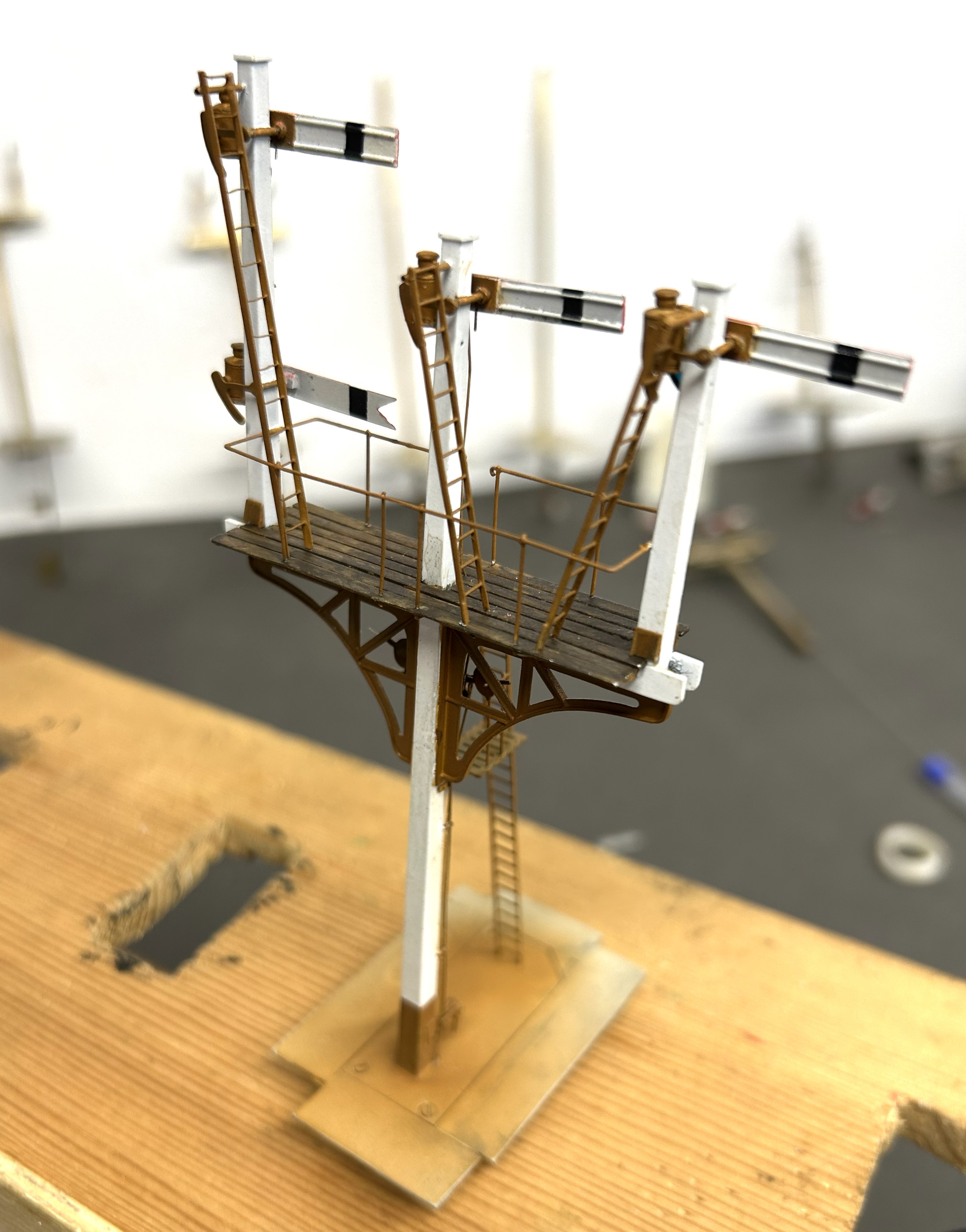
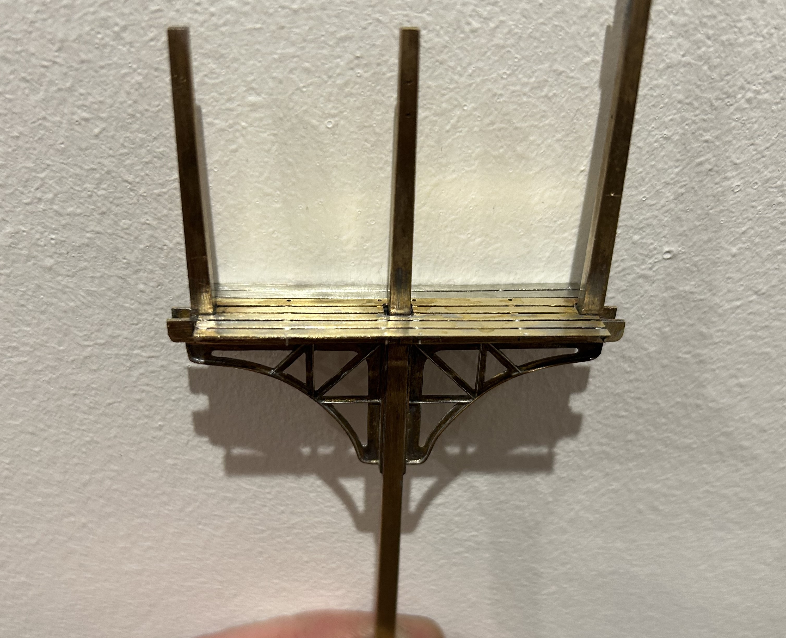
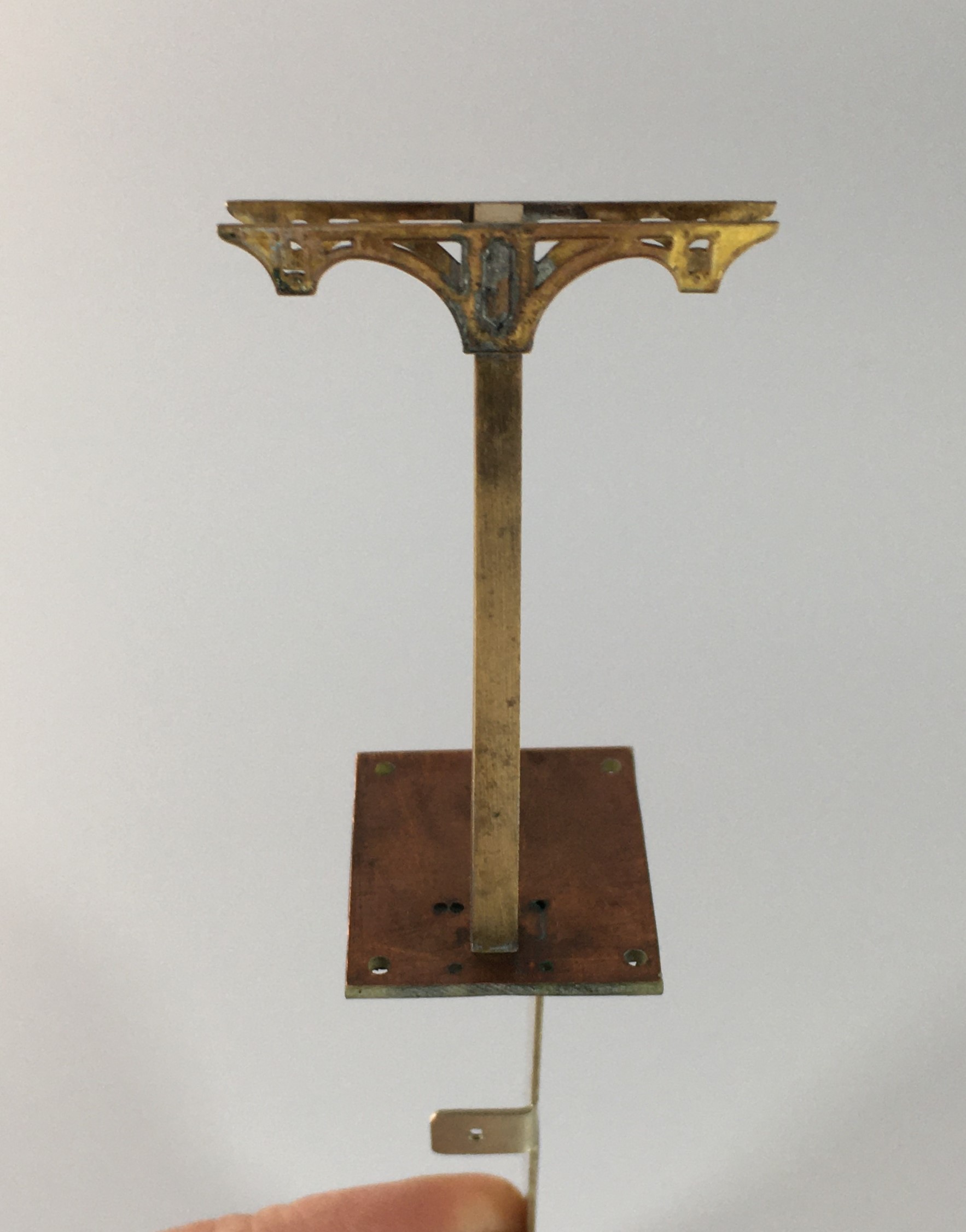
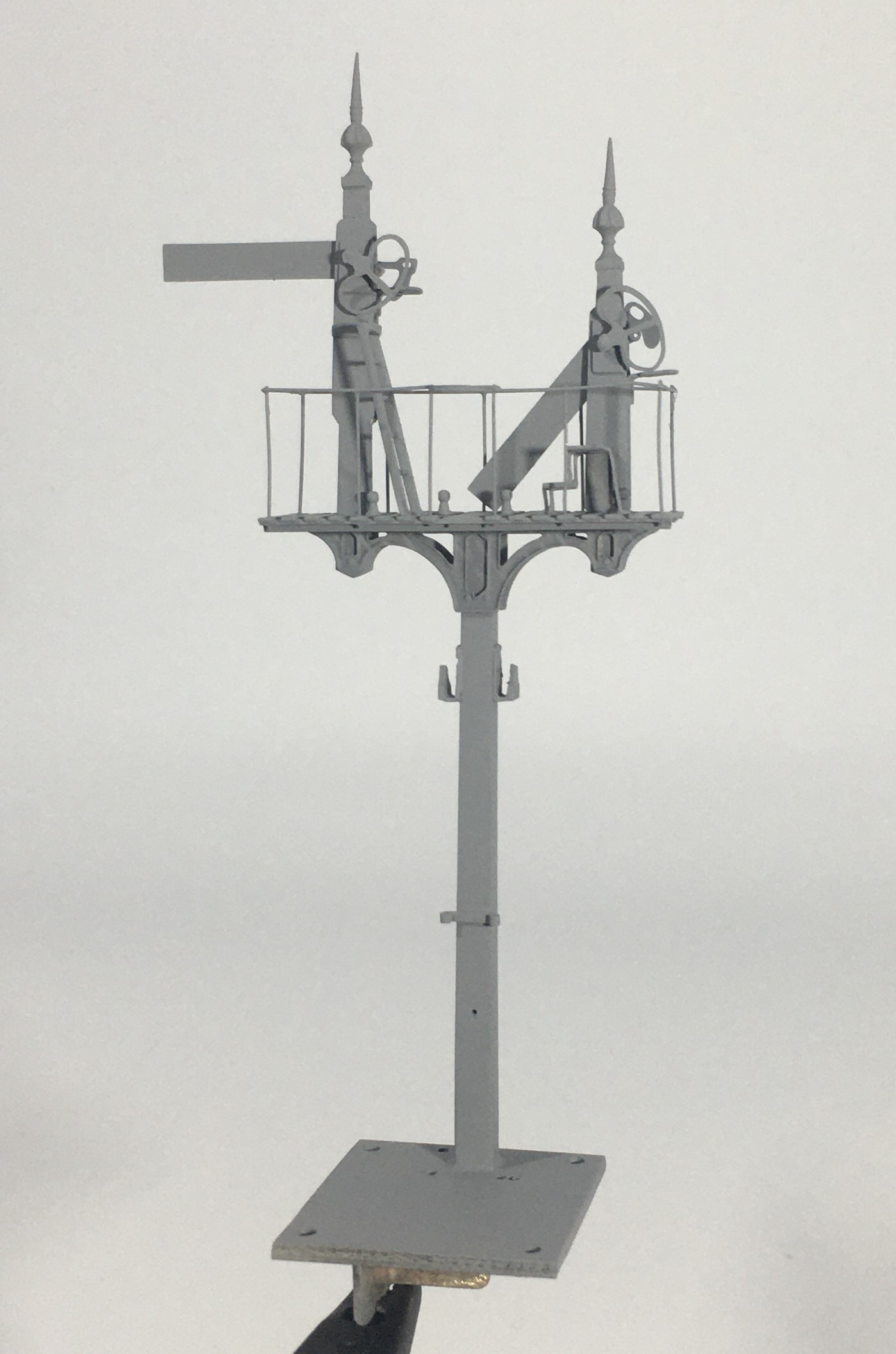
Having got the post and dolls in place, the next step was to fit the brackets.
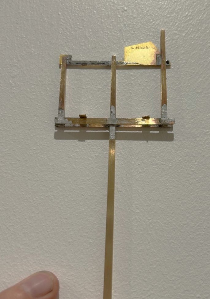
The LNWR were unusual in not using cast brackets; instead they fabricated theirs from sheet and angle iron. Those supplied by MSE are a flat etch and therefore feel a bit one dimensional.
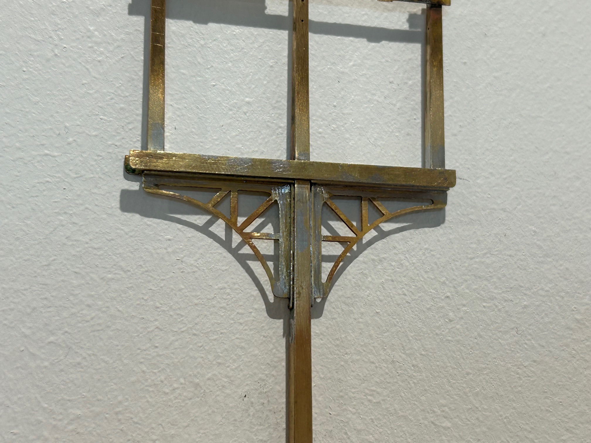
I therefore sweated on brass wire to one side of the strutts on both faces and also a plate on its outer edge. This helps give this a third dimension that was lacking before.

The next issue to be confronted was the landing where the MSE etch only provides a landing to the rear of the posts whereas this (and it appears many other LNWR signals) have landings both sides. I therefore had to produce support brackets and an enlarged area of landing. Foolishly, I forgot to drill holes for the guard rails before assembly, which meant that i had drill them in-situ. This is awkward due to the proximity of the dolls – it cost a couple of drill bits as a result and as a useful reminder to get it right next time!
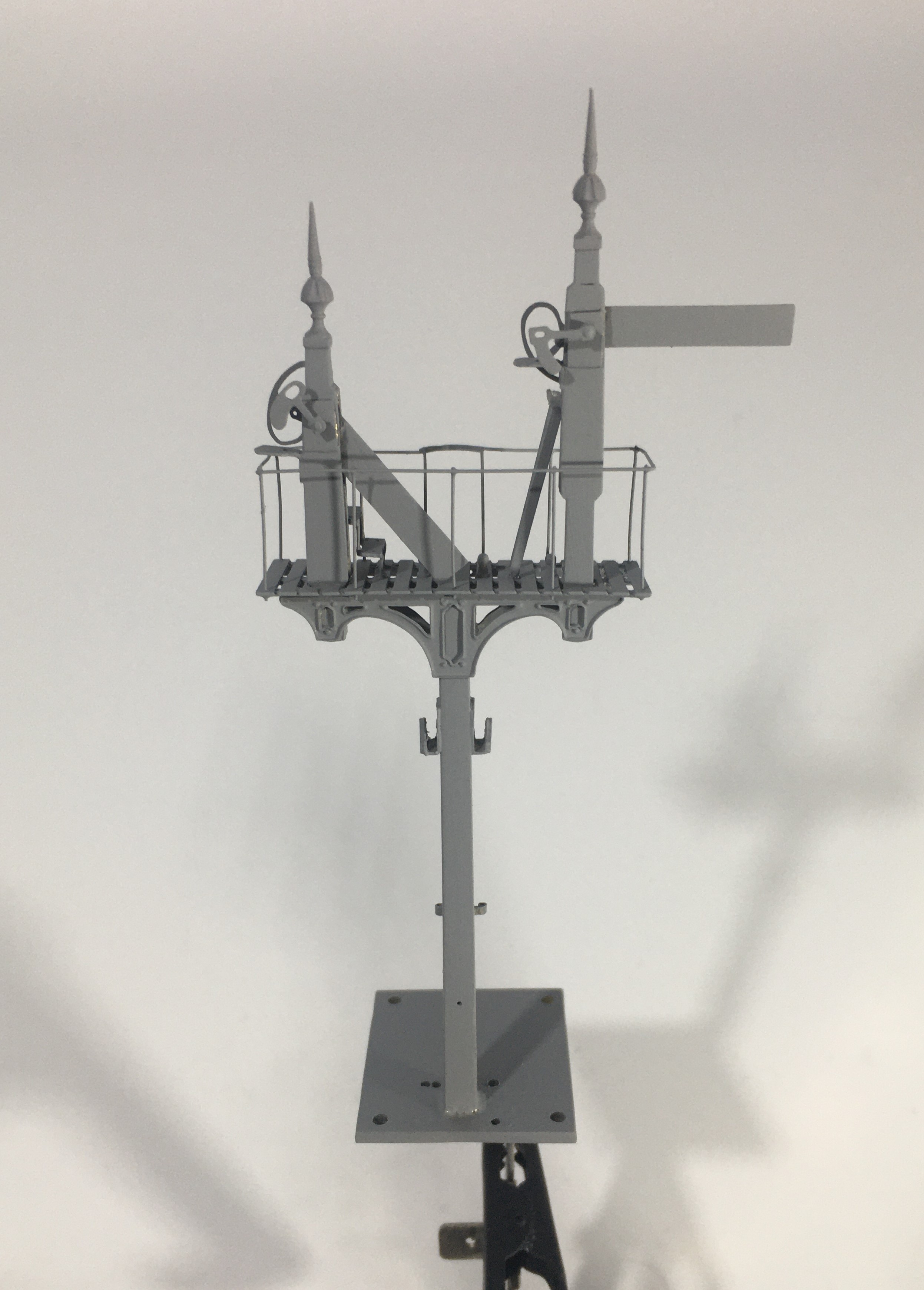
Next, I diverted my attention to the the mount for the servos. I now always form these with a lower base which is permenantly attached to the baseboard and into which a second detachable base plate is inserted. The two are a tight fit such that once a little scenary is applied to the top, the joint is invisible. These are secured together with 12BA screws to allow it to be detached both during the build and for maintenance but generally it is secured in place. This is because signals are prone to damage when being moved about and would need recommissioning to get the movement correct each time they are reinstated.
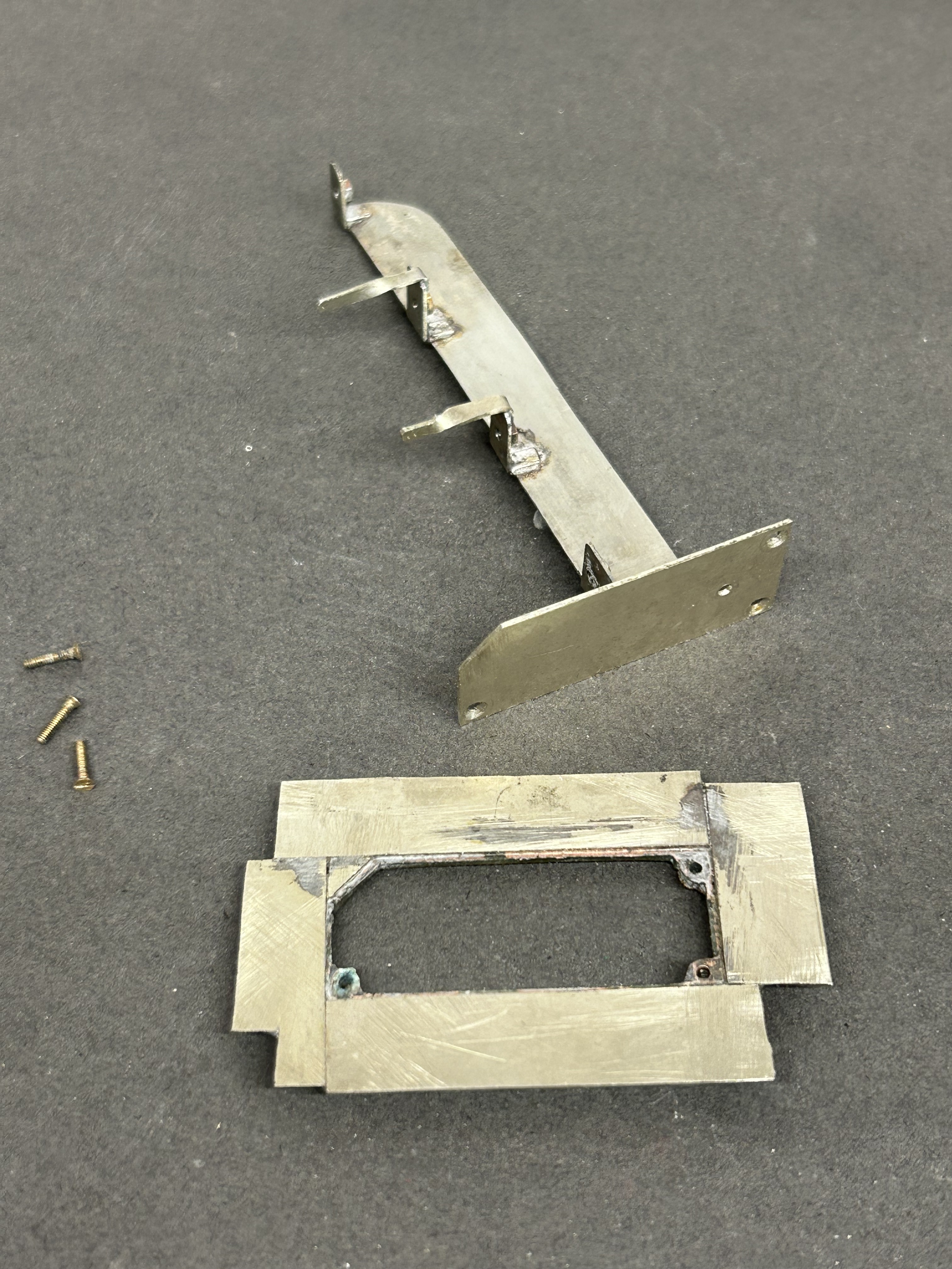
I drilled the underside of the post and tapped it 10BA in order to hold it in place. This enables me to secure it onto the base but subsequently remove it as I build it. I do solder it in place at the end of the build, but the ability to remove it during the build is helpful. The fact that the bolt holds it in place also makes it easier to get the post vertical, rather than trying to hold it vertical simultaneously with the soldering.
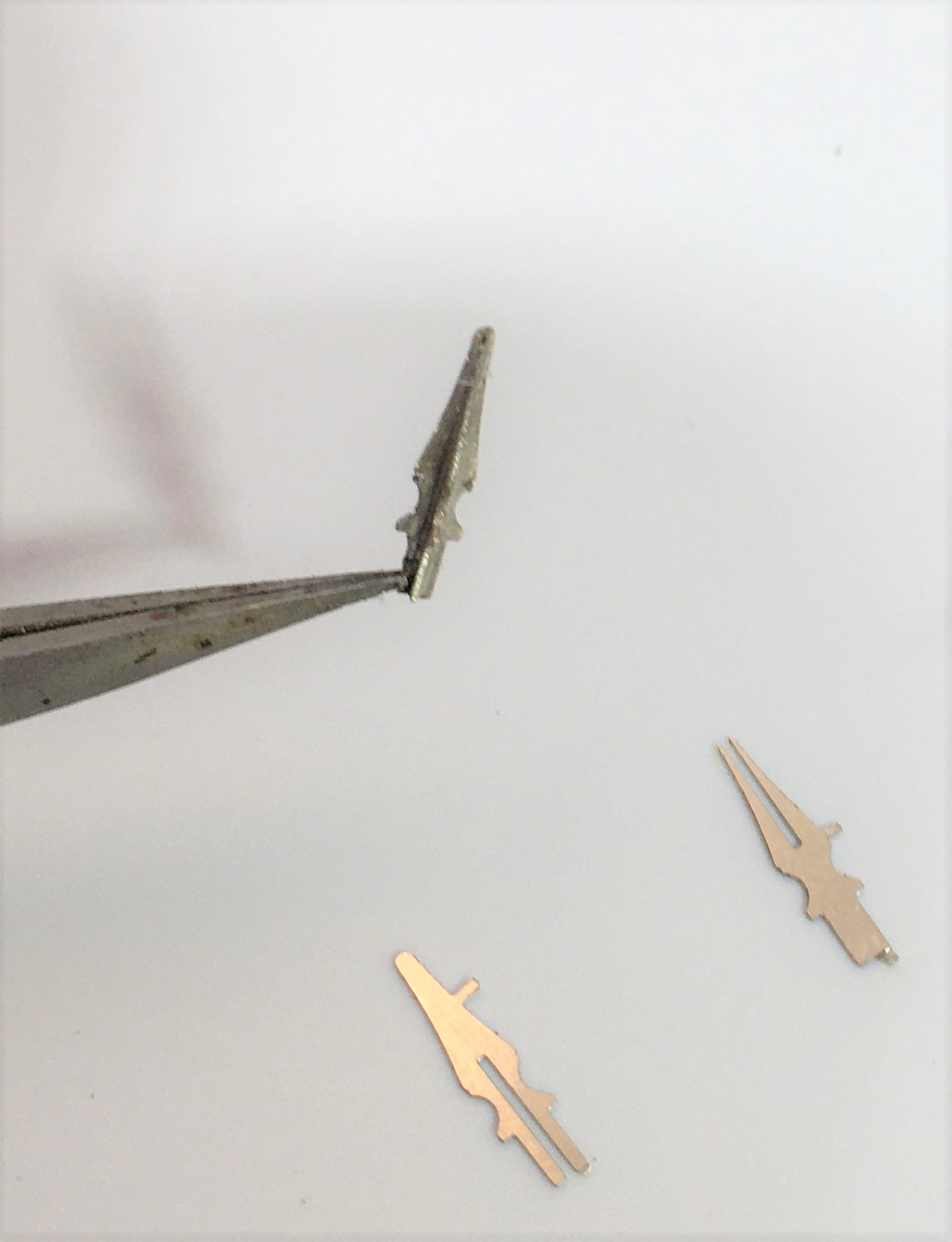
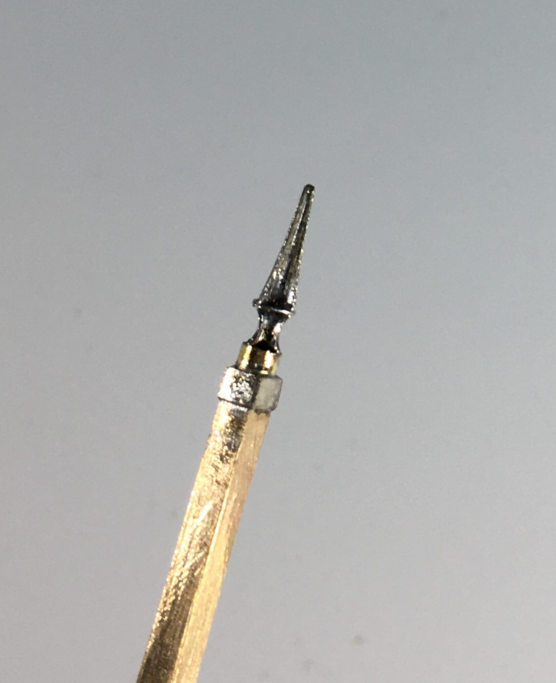
Whilst MSE do provide a white metal casting for the finials, I opted to fashion my own with brass as I find them crisper. To ensure these do not fall away as later tasks are completed, I use a high melting point solder for these and also include a pin drilled into the top of the post. Lamp brackets, lamps, the balance weight mount and some supports for the ladders were next.
I now have a recognisably signal beginning to form but the difficult bit, the movements are still to go.
")
Seasons Greetings (and Signals)
Work (at least real work) is now over for 2025 so I can get a bit of time in for turkey, mincepies and, of course, some signals.
I have built up a number of promises to make people signals; more than enough to keep me fully entertained for not only Christmas but quite a lot of time afterwards! It is time to start delivering on these promises.
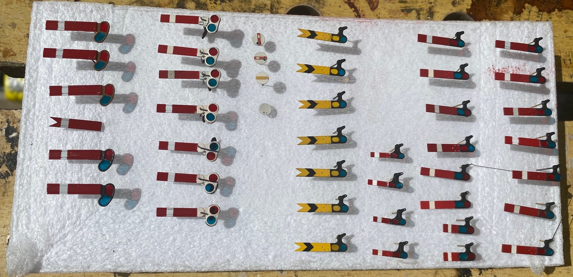
First uo has been to paint the arms. I know do these in advance as there is a lot of effort to paint them well and the best finish is by masking and spraying most of the colours. I can’t seem to brush paint to a good enough standard. I do, however, form the black shevron on the distant signals with black transfers as it is difficult to mask this neatly and the bars on the ground signals are a transfer from 51L.
I should be busy with this lot…………
In another departure, i have borrowed a milling machine to assist me in making the tapered timber posts. I form these from 4mm square brass section, a selection of files and a lot of elbow grease. It is a chunk of work for one signal but I have six taper posts and eleven taper dolls to do – I am not sure i have enough elbow grease to do this many!
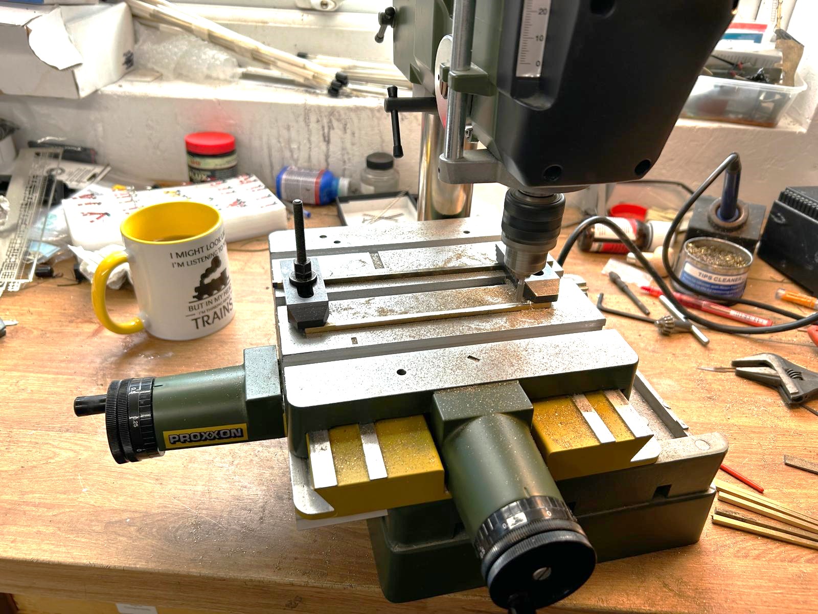
I propped one end of the post to form the correct taper with the mill travelling level. it was not without problems as the brass tended to flex (upwards oddly) where it was not supported. I ended up using the mill to take most of the weight off the metal and then went back to the files to finish the task off. It does reduce the effort, but it is still hardwork – and i have only done half of them so far!
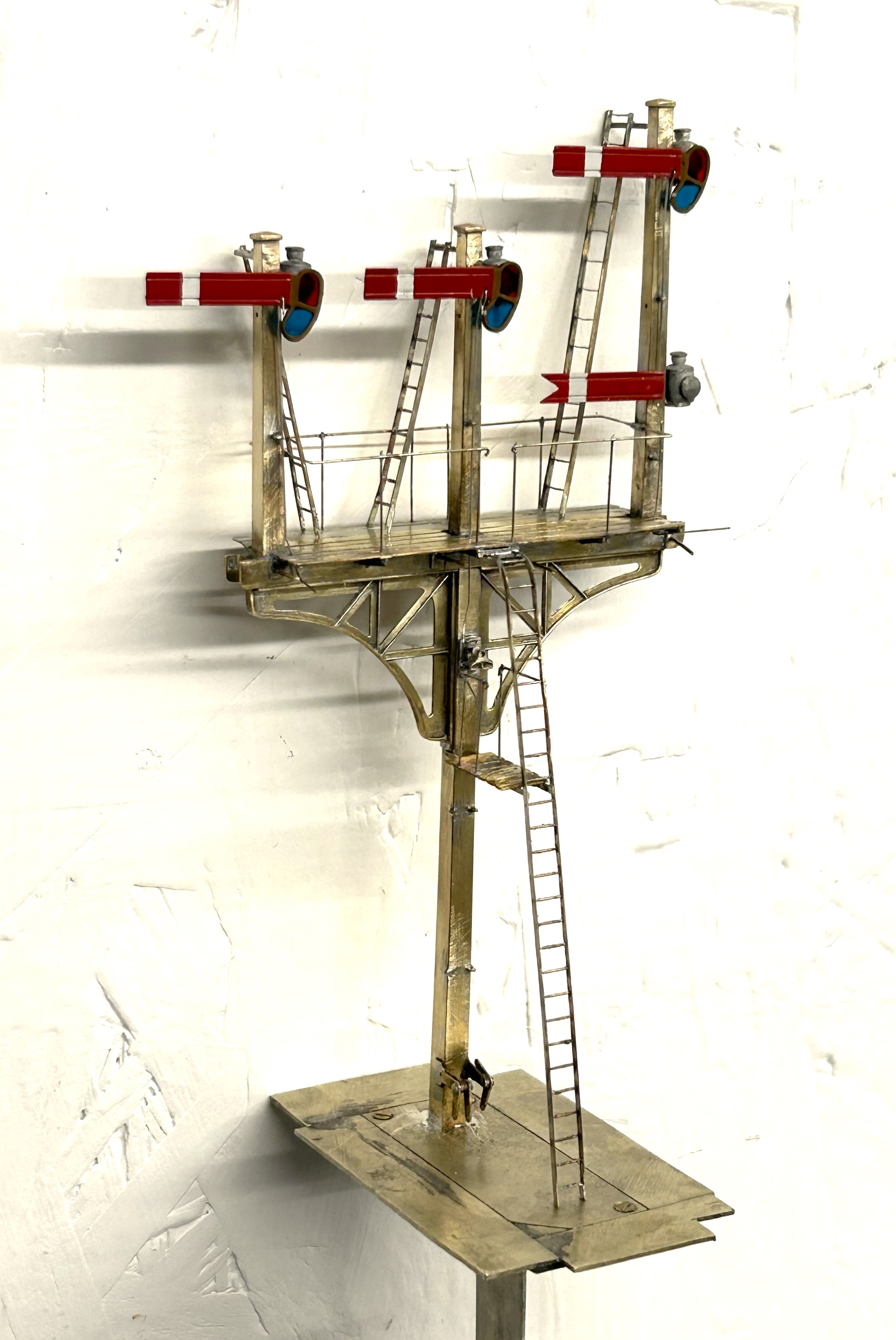
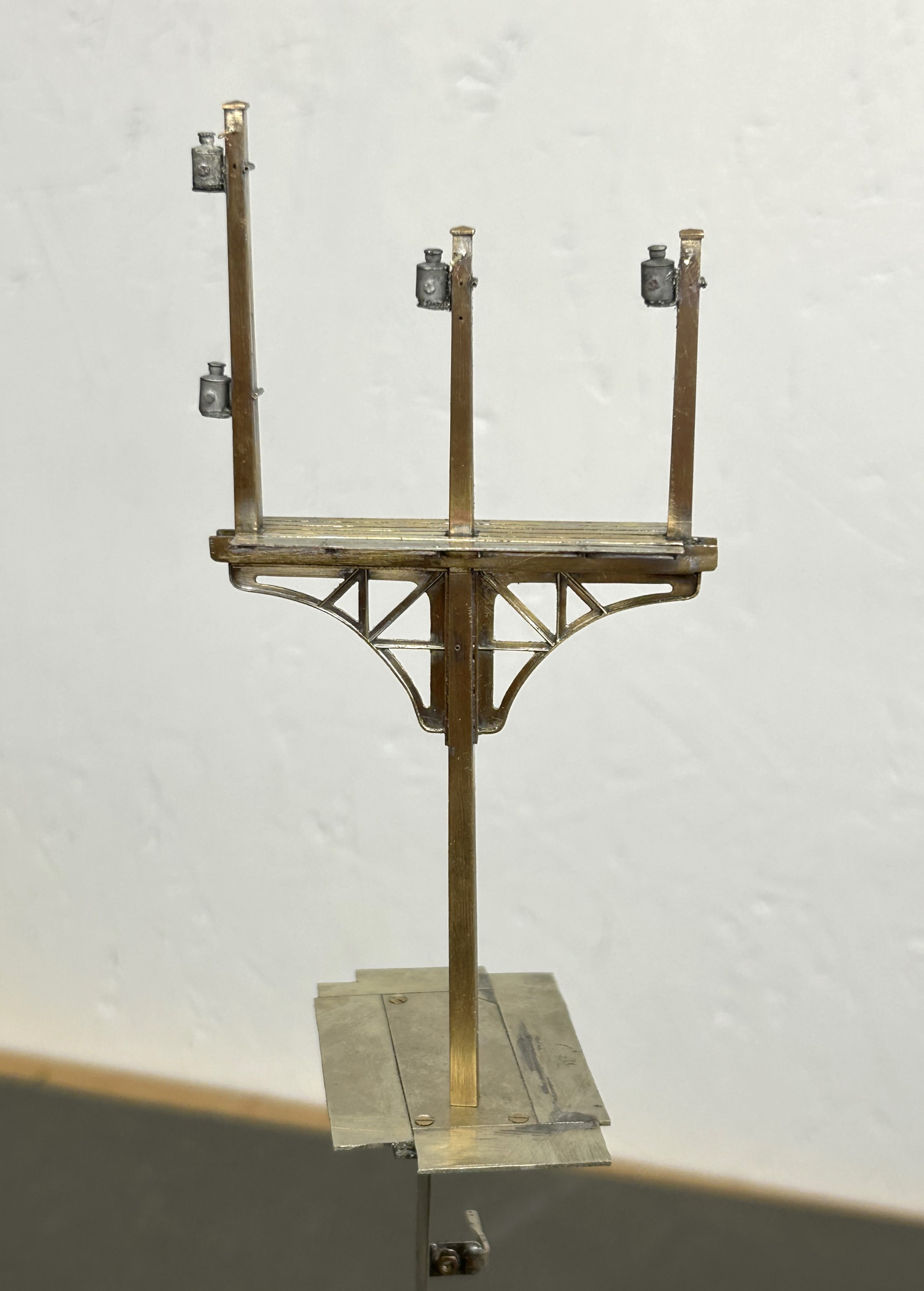
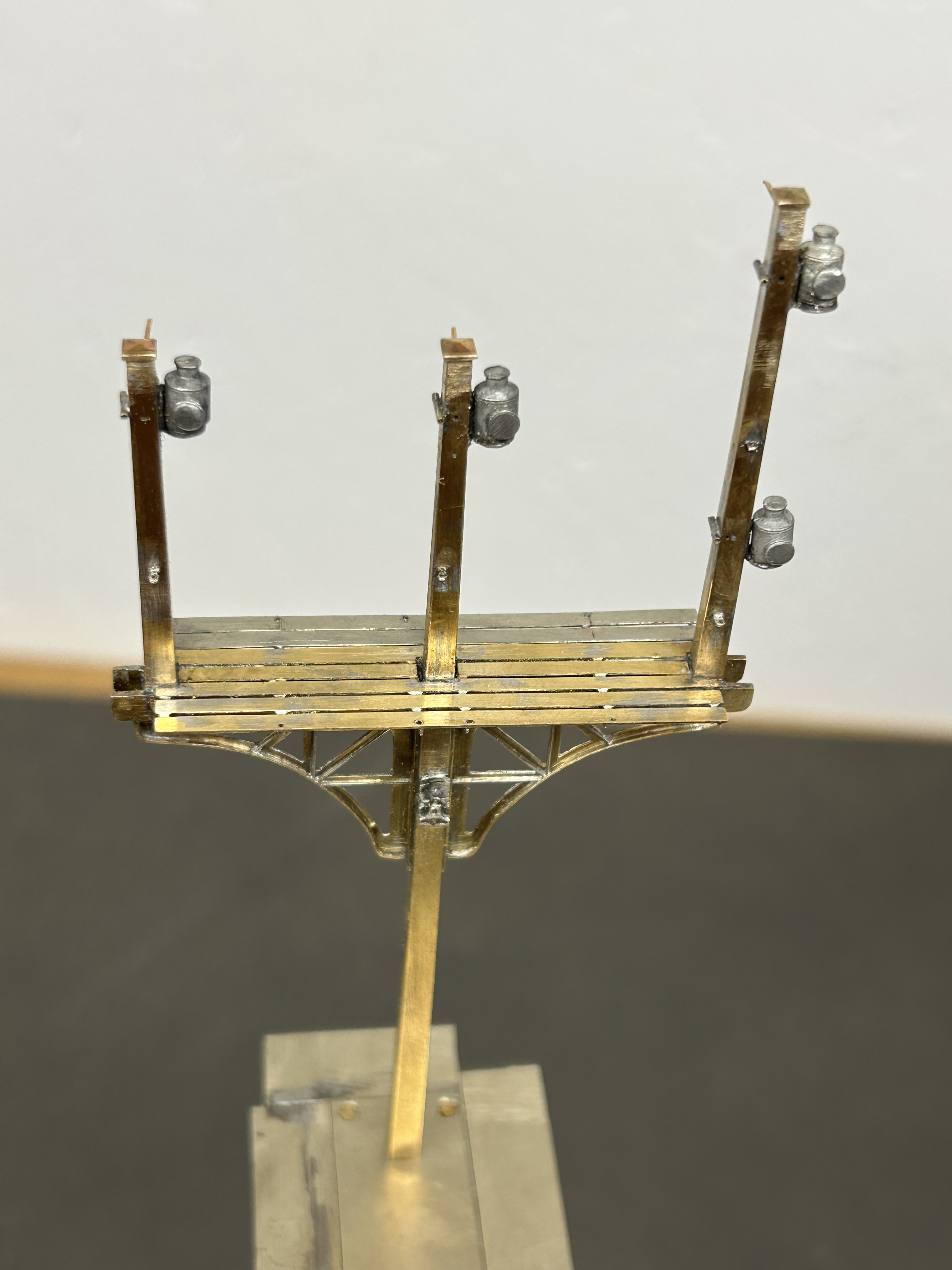
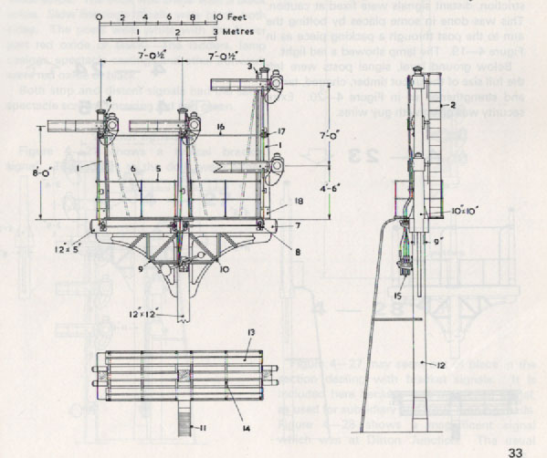
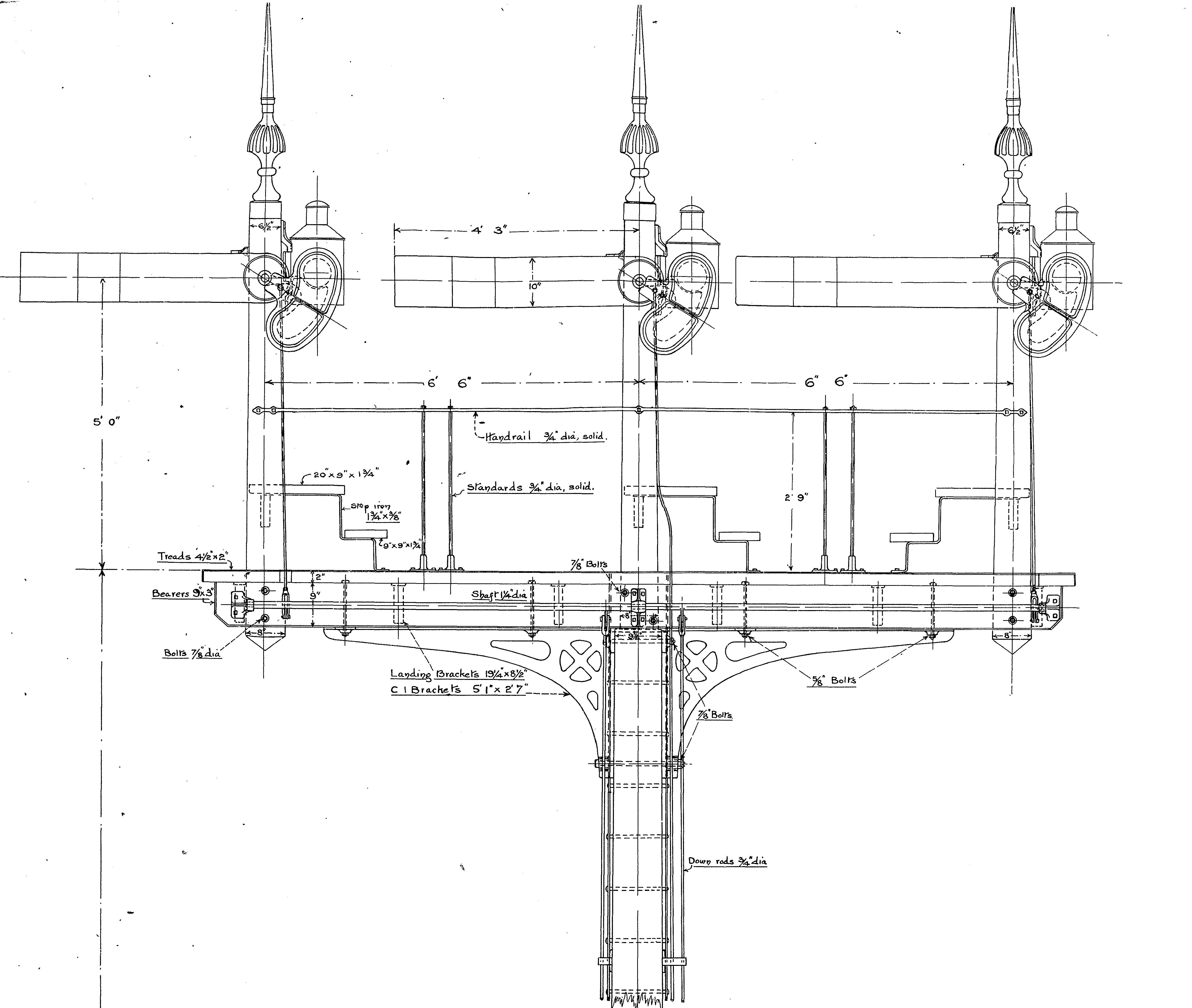
The first signal up is a LNWR three doll signal with three moving arms plus a fixed distant. Nearly as shown in this official drawing.
The basic posts and dolls are now in place; with various scarp etch temporary strutts to keep it square. Still a long way to go though!
So i wish you all a great Christmas and a Happy New Year.

Delayed Delivery – Part 2
Once the basic structure of the gantry is in place, the real task of making the signals signally commences. First up were the smoke deflectors and the brackets for the balance weights. Also fitted are the main portions of the fan route indicator, but that will be explained further once I get it going!
For the arm bearing point and lamps I am using some 3D prints produced by Steve Hewitt and available from Shapeways. They can be found here https://www.shapeways.com/product/JJRSB … arketplace. They are fairly expensive but they are neat and save a lot of manufacture. There is, however, a but – they are very delicate and I am very fearful of thier long term durability. I am highly likely to draw some of my own up and get them cast in lost wax. It will make them even more expensive but I have about a 50% casualty rate at the moment, so maybe in the long term it will be cheaper!
The arms are Masokits, these are definitely the best available arms for LMS/LNER/BR semaphores. This is especially true of the minature shunt arms as the MSE ones are simply too delicate to bother with (imagine how do I know that………….!). So this is where we are now at with the arms mounted temporarly on the bearings.
There are five movements in the down direction (three of which operate via the route indicator) and then a pair in the up direction – hence the back to front arms.
The plates at the top of the dolls are mounting points for ladders. It transpires they are wrong and have already gone!
So the intensity level has dialled up a notch with these portions (especially breaking the bearing/lamp fittings) but it really gets interesting when you try and make these things work.
I don’t know myself yet (although I know for the couple of arms I have finished, so I have an inkling), but i think it might be fun to have a little sweepstake on how many moving parts there will be in the finished gantry. Five arms, three fan route indicators and each is operated by way of angle cranks. Each arm, crank and intermediate wire counts as a moving part, as do the servos………………..guesses please?

Delayed Delivery – part 1
After a long pause, caused by that irratating thing called life getting in the way, I am looking to deliver on some long made modelling promises over the holiday season.
The major task is a rather full on gantry signal with no less than eight movements on it (which is an improvement, when initially designed it had nine!), including a rather natty fan route indicator. This is for a friend’s layout and is in return for some signal cabins that he built no less than 15 years ago – I told you the promises were long made! Mind you, he hasn’t got the layout fully running yet, so I am still ahead of him!
The gantry spans only two lines so it can be formed with channel section. There are good drawings and pictures in LMS Journal no 5 of this. I have made mine from milled brass section and then the landing was a custom etch I designed as it takes a surprisingly large amount of material and effort to construct this from scratch. These etches included the doll base plates although the dolls have a thickened tube at the lower level which of course I forgot and had to undo later work to put on!!
The signal is to be located on an embankment which meant that I could not simply put flat base plates on the foot of the gantry columns. Instead I have constructed a housing that matches the slope of the embankment and then the baseplates are partially sloped to match this with square sections representing the foundations of the prototype columns. Below these baseplates I have then formed housings to take the servos which will eventually operate the arm actions.
So far, this is pretty easy modelling (although I lost a number of drill bits opening up the stanchion positions on the landing – grrrrrr!). The tough bit comes next……………
There are potentially two viewers of this thread who might be thinking that I have long outstanding modelling promises to them too……………I am also working on one of these too!!
Only the printable words for this Wednesday!
Hmmmm……..
A signal imitating a Fresian cow was not the effect I was after…………..
Halfords etch primer is obviously not that etchy!…………….. So someone will be waiting a tad longer for their signal than I thought…………

And now a Midland signal…..
Whilst the NER signal from my last post gets itself painted, I turned my attention to the next few signals – in this case these will be Midland lower quadrants.
A lot of the character of a signal is in its finial and if this isn’t right then the model won’t convince. In addition, they are also very vulnerable so need to be durable. Therefore, my conclusion is that white metal finials do not cut the mustard – they are too delicate and too clunky. Thus, in this case I decided to make my own – I came up with this which starts with with some interlocking etches:
And then a bit of brass tube as a collar at the base
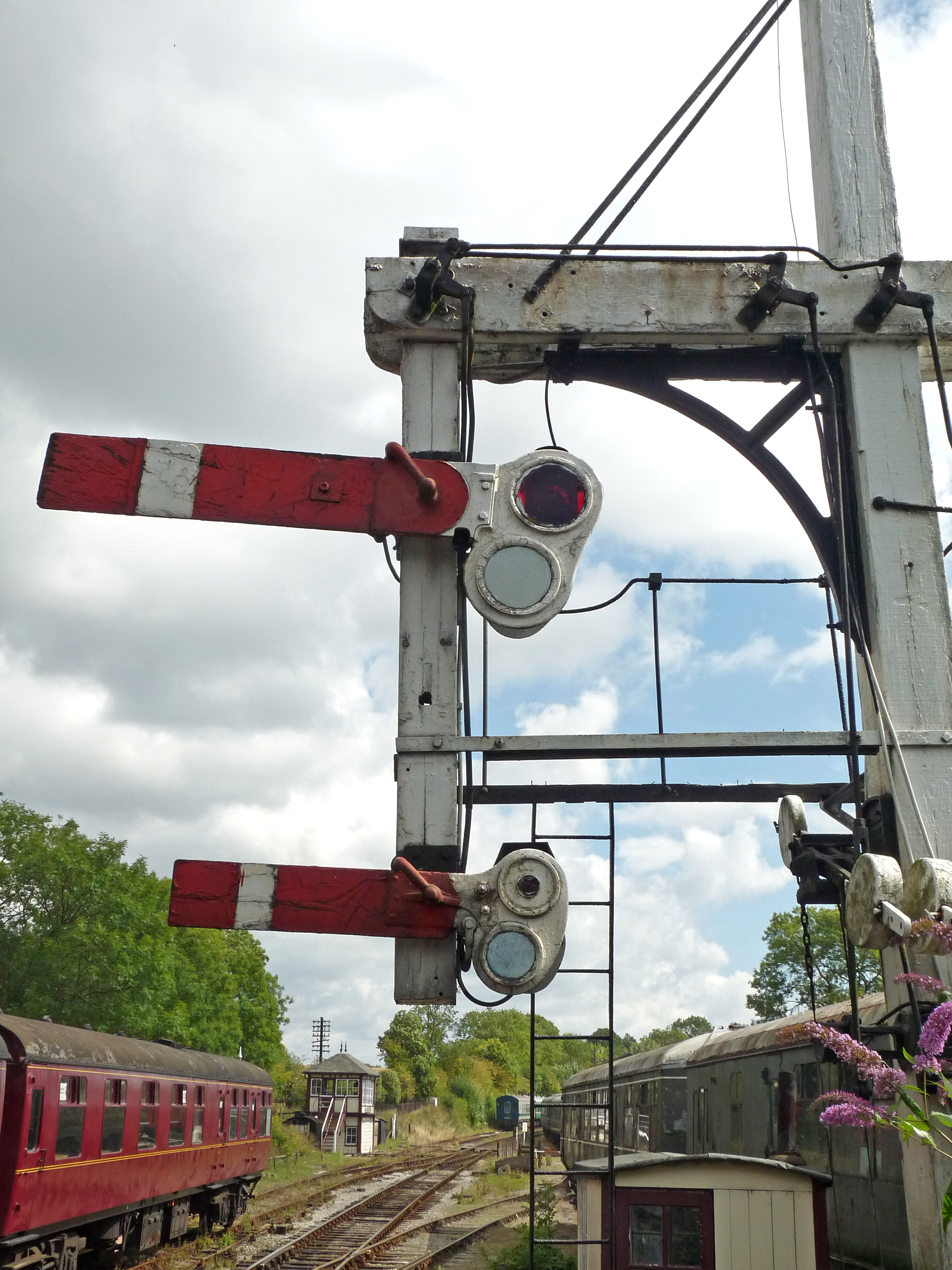
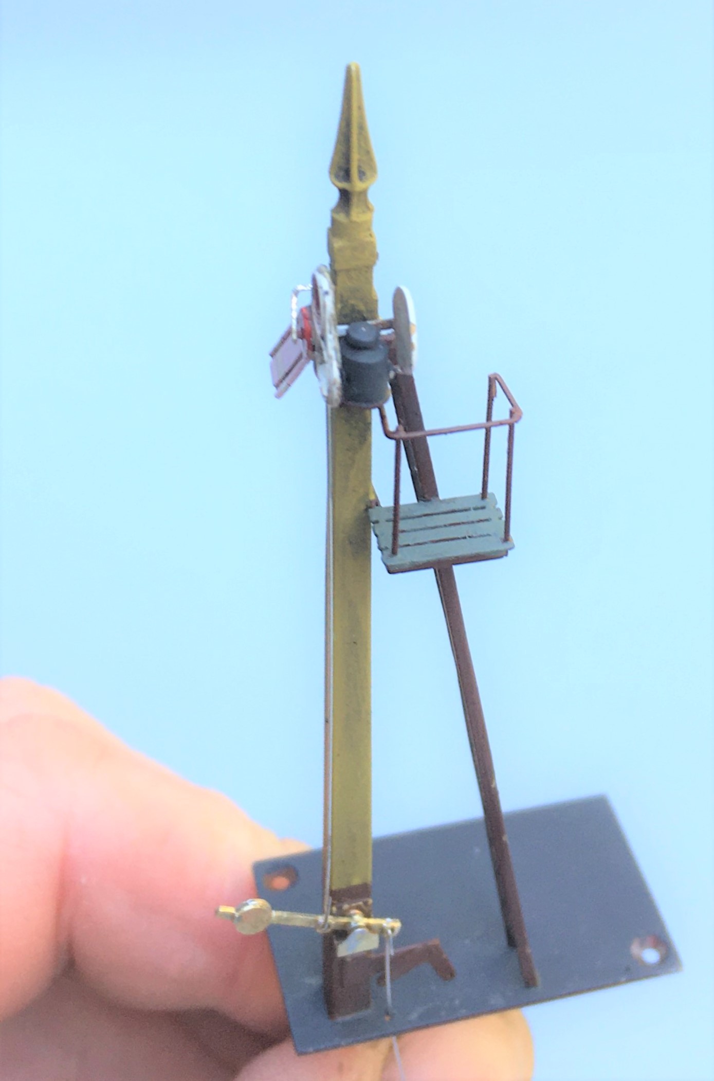
The Midland’s style of signals do have a few idiosyncrasies; one of which is the way that blinders are fixed. Instead of being fixed to the spindle these are secured to the arms and wrap around the lamp. This can be more clearly seen in the photograph below.
The other key change was in the manner in that the arms are secured to the posts. Instead of being pined through the arm and secured at the rear, the Midland used a bracket to the front of the post with a plate that wrapped around to the front of the signal to support the arm to the front. This can be seen in this view of a rather nice gallows signal at Butterley.
The bracket can be seen in this view below and I then created a pin that fitted into the bracket and slotted over the spindle.
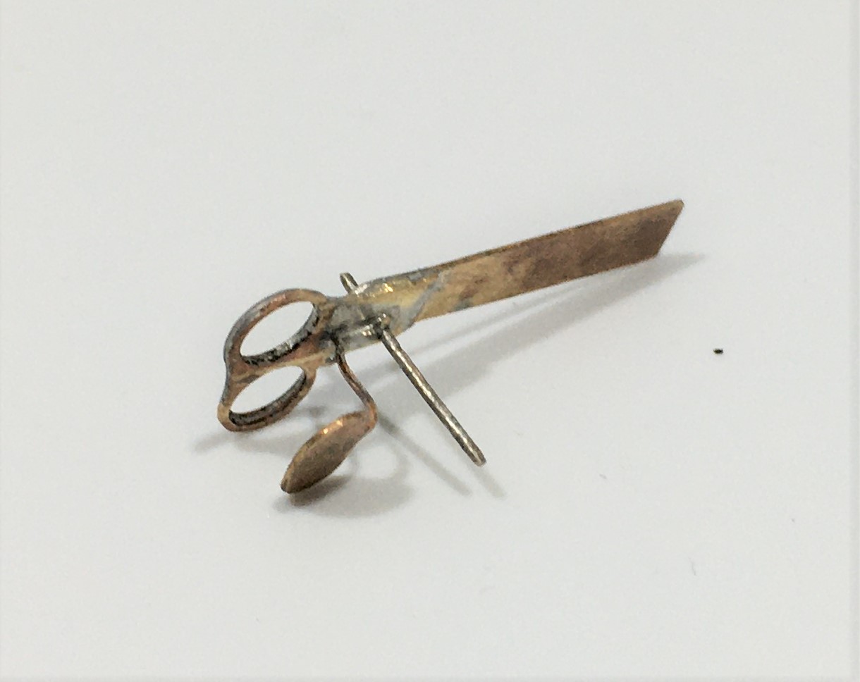
I have bought a new light box for taking photographs in. Whilst I am still getting to grips with it, when it works it does produce much improved pictures of models. These almost look like an images of a 3D model on a computer screen. The pliers at the bottom of these views do rather give the game away!
The Midland were a bit odd in their choice of colours for their signals. The posts were “primrose yellow” but this quickly dirtied to something akin to cotswold stone is what the book says, so this does give something a little different. This is my representation of this with a decent dose of smokey dirt – when you look at contemporary photographs many signals were not only dirty but entirely smothered in smoke. I haven’t gone that far yet, but its going to need to be done!
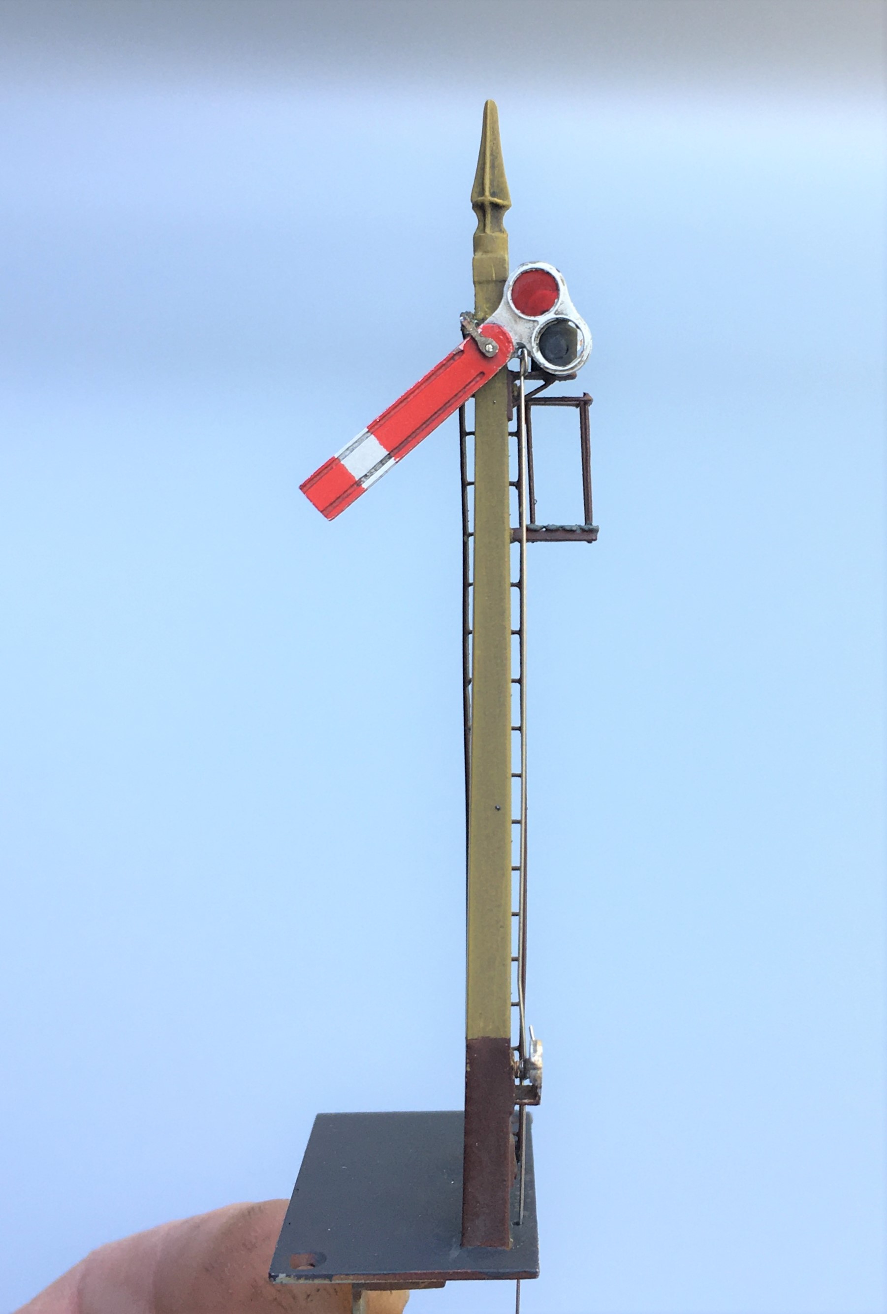
As can be seen, this still needs connecting to the servos and the touching in of the paint on the parts that I fit after the main assembly (the balance lever and the plate that wrapped around the signal arm).

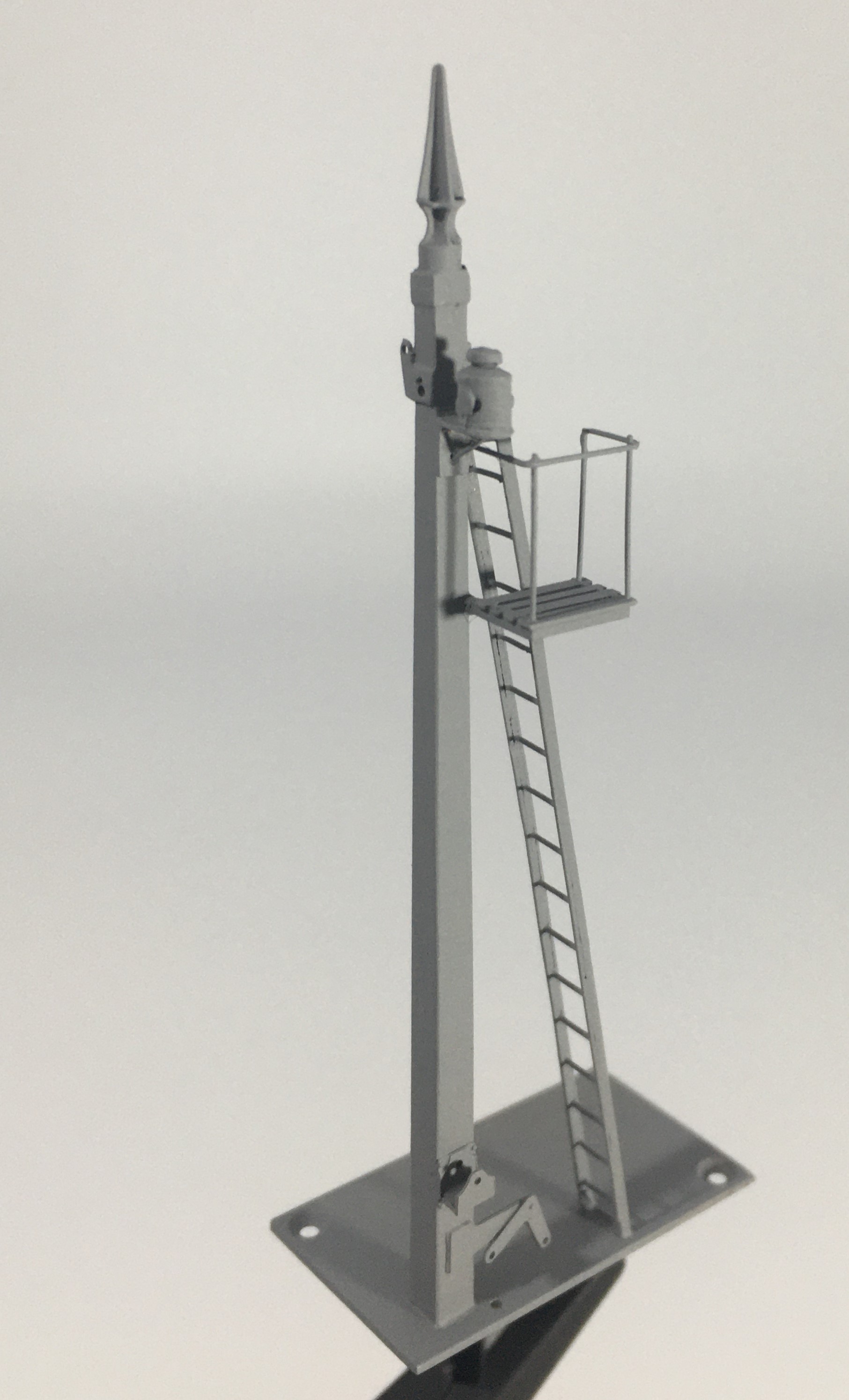
Benfieldside’s Missing Signal
When my friends acquired Benfieldside, it had suffered a bit of damage, notably to its signals – in essence it was this that got me volunteered for their restoration! One signal that puzzled us, however, was the up starter which was missing altogether and we could not unearth any photographs of it. Ultimately, we decided that it should be a two doll signal to also control the adjacent bay (which did have a signal, albeit inoperative) – so I have set to in order to fill this gap.
The line is set in Cumbria and is an imaginary westward extension of the Newcastle & Carlise line. In theory, therefore, it should not have the heavy cast iron brackets that the NER used. However, in reviewing the NERA’s signalling book, it became apparent that there were quite a lot of strays of signal designs, so I had an excuse to build one!
As this particular signal is going to be platform mounted, I did not need to sort out a mount for it and moved straight to the post and bracket, the latter being by MSE which I had in stock.
I then moved on to the prefabrication of a pair of dolls, each with slotted posts. This is made up of solid square section filed to a taper which is then cut and each end then has a tongue filed on it onto which flat plate is soldered either side to create the slots. I used a variety of temperature solders to ease this process but it was not easy – I did have one gum solid which resulted in a need to dismantle it and start again! As alluded to in the previous post, as these are slotted posts I had to depart from my usual practise of fitting the arms after painting as it is not otherwise possible to solder them to the spindle for the arm.
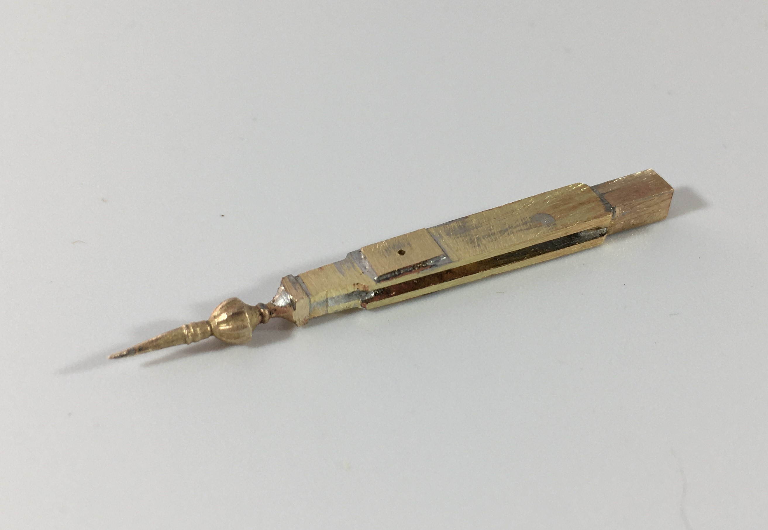
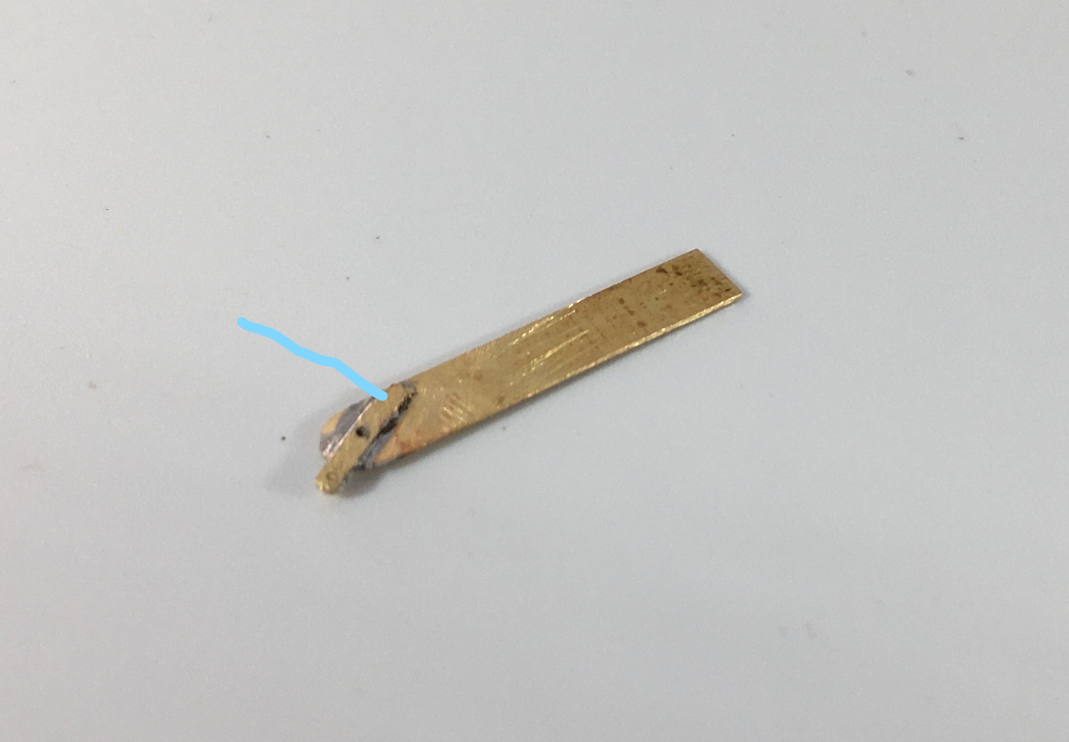
As mentioned in the last post, I came up with a bit of a dodge to successfully (well, in two of three cases!) to solder the arm to the spindle without gumming it up. By extending the ear that forms the point at which the operating rod attaches to the arm forward a bit (see the line below), it provides a point at which the soldering iron can be touched. If you use a slight excess of solder this allows the heat to transmit to the spindle and make the soldered joint.
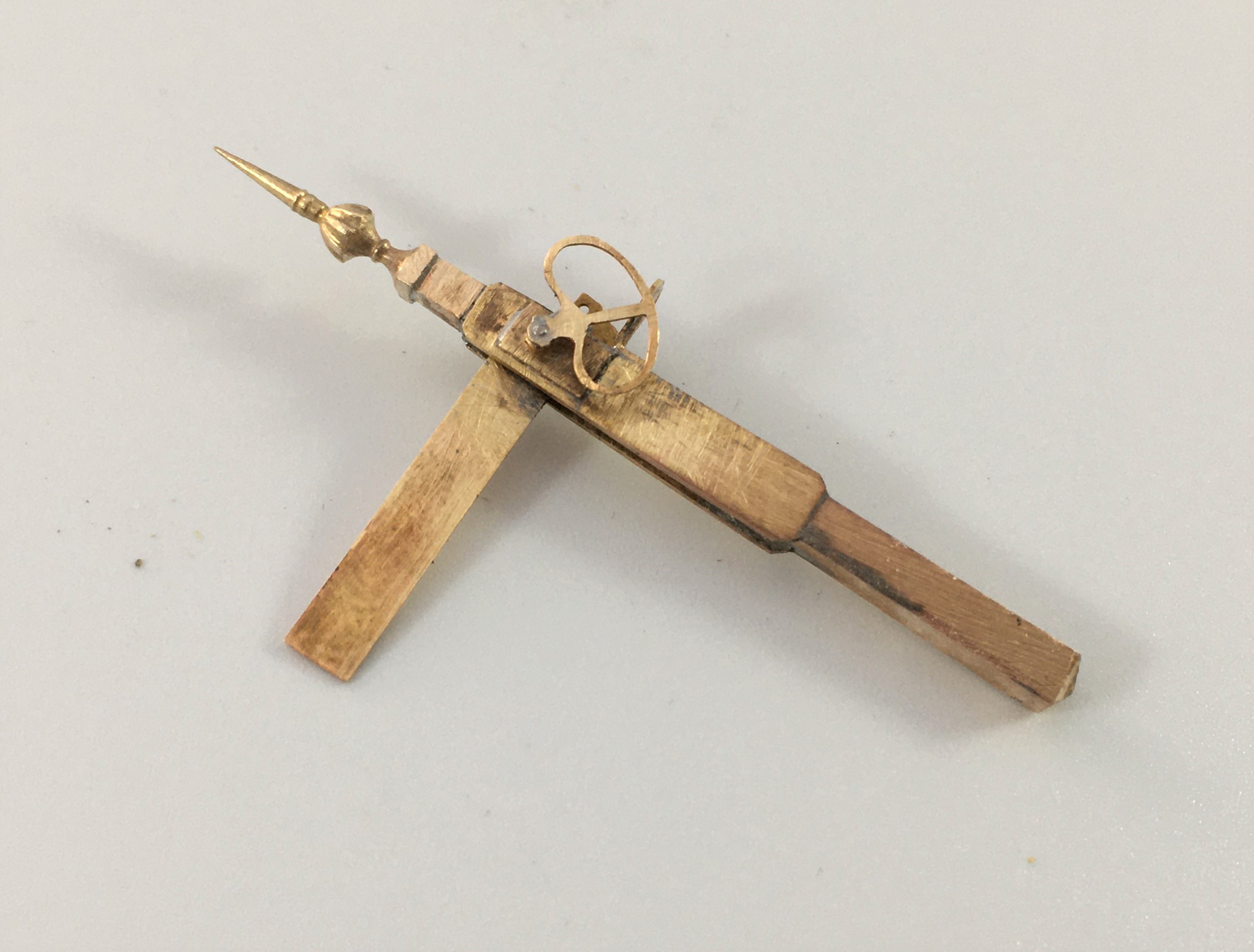
And this is what you get with a prefabricated doll, ready for the next stage of assembly.
And below of the pair of dolls now inserted to the landing.
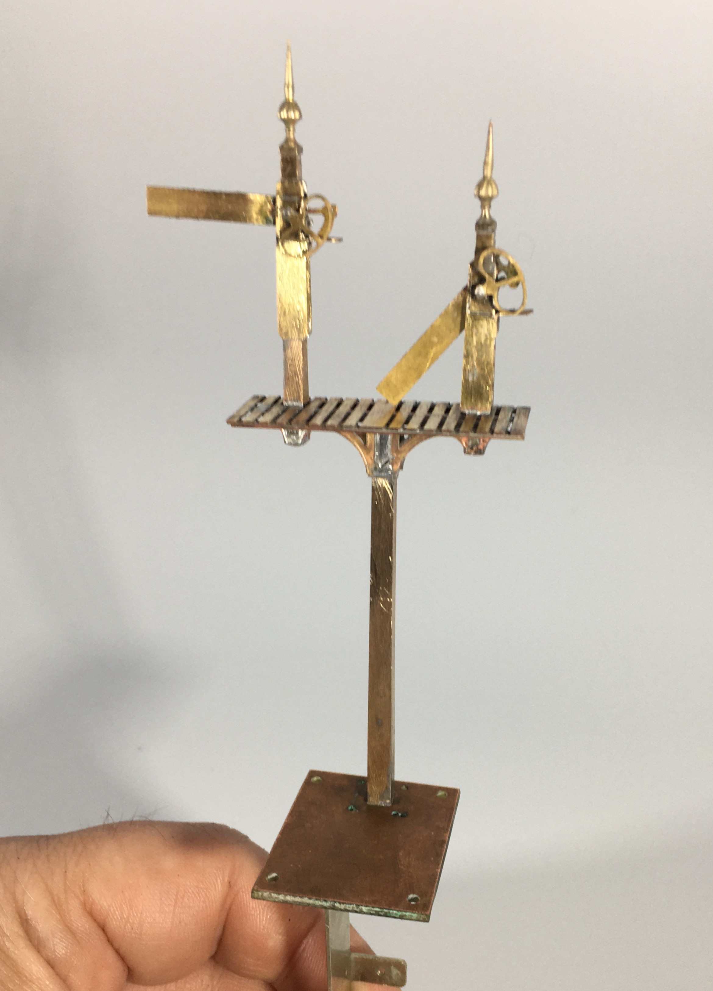
Even at this stage, there is still a lot of building to do as there are handrails, the main ladder, steps and ladders to the dolls, the operating mechanism transferring the movement to the dolls all to do. In respect of the latter(I used rocking cams in this case – you can just see the use of some handrail knobs as the bearings in the photos below, the cams will be fitted after painting.
Slightly peculiarly, the NER built their landings in front of the arms whereas all the other signals I have yet built have these in the rear (excepting gantries, which can be either or both!). This view shows this most clearly.
The main ladder is not visible in the views as I have made this detachable because it is much easier to spray paint these (and better, it is not easy to get a thin coat of paint by brush application and it thickens up the fine detail of a ladder too much.
The grey primer is pretty cruel to modelling efforts but on the whole, I am pretty chuffed with this!
Tatty’s Top Tips – Signals
A mere three weeks ago, but a lifetime in the past now that we are in the middle (or more worryingly, perhaps just the beginning) of the Covid-19 crisis, I was a demonstrator at the joint EMGS/Scalefour Society skills day. These skills days are not really exhibitions and are instead aimed at passing some skills on to the visitors – thus they are primarily a hall full of demonstrators with only the odd layout or two to break up the rows of desks.
Here I am, in a shockingly creased shirt (!), and as you can see, I am demonstrating signal construction. I am pleased to say that at the skills day I had a solid stream of people engaging with the topic all day; so much show I had to pull down the shutters for a brief lunch as otherwise I really would not have stopped all day!
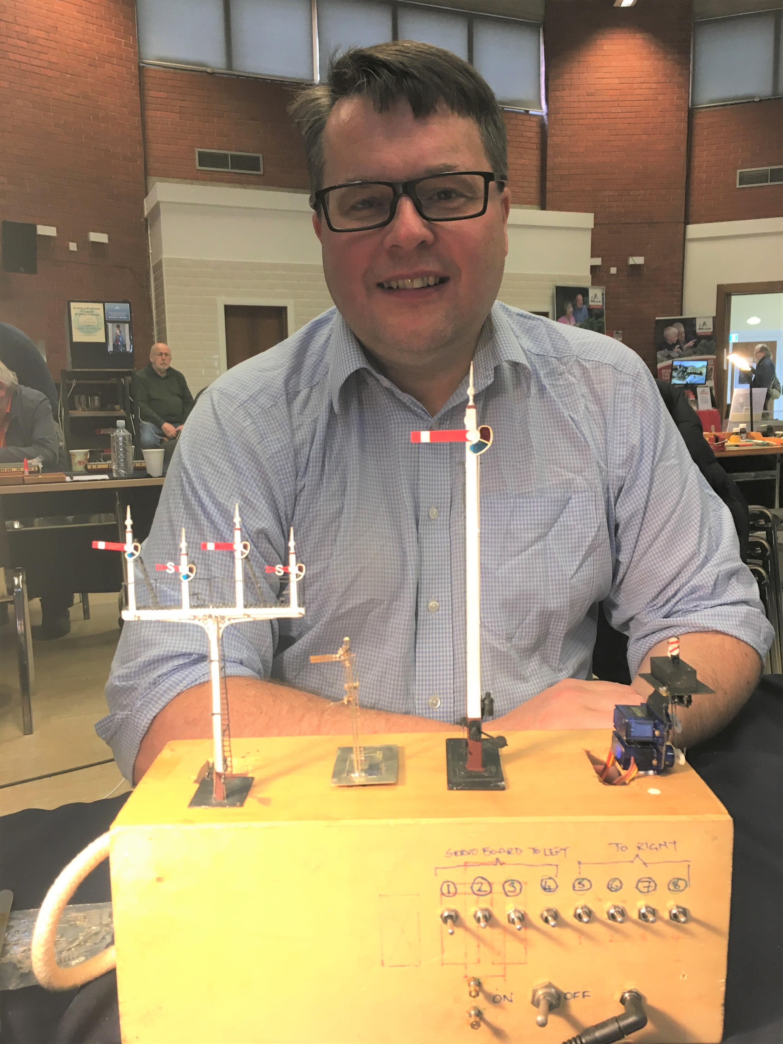
By way of preparation for the event, I thought about what I have learnt about building signals and distilled a list of my top tips. These proved to be the cornerstone of my conversations with people at the Skills Day so I thought it was worth repeating them here on the blog.
Planning Ahead
- Conceive how you are going to mount the signal; where and how, what is above the ground or below the baseboard – which might well mean you also need to;

The base and mount for a two movement servo controlled signal
- Decide how you are going to operate the signal, how is the drive mechanism to be mounted and what does it need to be connected to mechanically/electrically;
- If you are going to illuminate your lamps, you need to decide how you are going to run the wires to the LEDs or fibre optic cable. It is possible to use the post as a common return but you still need one wireway;
- Consider how the movement is to be transmitted (especially bracket signals) and how you are going to replicate this? Multiple movements in close proximity to each other can lead to interference, compromises to reduce this risk are sometimes desirable (especially for triple or more movements in close proximity);
- Conceive how you are going to paint and assemble the signal before you start – it is generally easier to paint arms and ladders before you assemble them so it is possible to create sub-assemblies to be attached later – the touching in of local areas of damaged paint caused through assembly is a small price to pay for the ease of painting the remaining areas;
A Southern rail built home signal; the post was formed of two pieces of nickle silver rail.
Construction
- Tight, tight, tight – the most important part of building a signal is to keep all holes of operating parts as tight and snug as possible as slack leads to sloppy movement;
- You will use a lot of fine drills, down to 0.3mm, and a good quality pillar drill will mean you break rather fewer of them!
- Use the file up the length of the post not across it as much as possible – the files leave less scars and any that do occur mimic the grain of the wood;
- Pre-form or pre-drill elements such as balance weights, holes to the posts or landings early on before they are assembled when it is easiest (well potentially!);
- The prototype of most of the components to a signal are pretty delicate with fine sections; thus, to capture their character these needs to be similarly fine, however:
- There is a trade-off to make with the operating components such as balance levers which are typically best made over scale and with laminated brass to give them more strength;
- Generally, build the bigger more robust elements first and potentially alter the build sequence in the light of thermal mass and whether adjacent items might be disturbed by later additions – consider using different temperature solders and prefabrication of elements such as dolls with all of the lamps/landings finished;
A prefabricated doll and arm – I wouldn’t normally fit the arm until after painting but this is not true for slotted post signals
- Don’t use the flat etched ladders, they are too flexible to look real. Either use the built up versions or solder 0.3mm wire on both front and back of stringers and file the outside face flat – they look more realistic and are more durable.

A flat etched ladder with 0.3mm wire being soldered to the stringer
- Lots of delicate parts and complicated sections means that ultrasonic baths are really helpful for cleaning without damaging elements;
Slotted Post Signals
- Not the easiest because of the need to solder the arm to the spindle inside the slot. Use a laminated piece to the ear that is the point at which the operating rod attaches to the arm and extend it cross the back of the arm by 3mm so that it is would project beyond the slot slightly. Be liberal with the solder but make sure that the rubbing faces are cleared of any excess. Wrap the arm in cigarette paper and insert it into the slot. After the spindle has been inserted, touch the cigarette paper with light oil and allow it to soak through. Then put a little flux on the laminated ear and apply the iron. The heat will transmit along the solder joint and reach the spindle.
Operation
- Protect the signal from excess throw; they are delicate – therefore set the servo up to an approximate centre point through before connecting it to the model;
- Leave room to be able to see the signal as you are setting it up, otherwise it takes ages and a lot of bending under the baseboard;
- If you are going to illuminate your signal, understand what the right colours would be – oil lamps are relatively dim (so you need to resist down the voltage) and quite yellow (so modern LEDs need to toned down).
Dimensions
Dimensions were not standardised even within a company, let alone between, so offering directions on dimensions is dangerous – all I will say is these dimensions are commonplace:
- Single post wooden signals – 6” square at the top and then tapering out 3/16th of an inch for each foot of height (1.5% or so)
- Wooden doll posts – 7” square at top and tapering as before
- Main post for wooden bracket signals – 10” at the top and then tapering as before
- Single post tubular signals – 5 1/2″ to the upper portion and 6 1/2″ to the lower portion. The height of the lower portion varied with the height of the post (for details, see LMS journal no 4)
- Arm – centre pivot – 1′ 6″ from the top of the post; second arms 6′ 0″ below that;
- Spacing between dolls – 6′ 0″ or 6′ 6″ (less for shunt arms)
- Height of handrail to landings – 3′ 0″
A GER three doll bracket signal

Best Work Trip Ever – Signals and a Sad Reprise
Following the tragic events in Sri Lanka recently, I pondered whether I would complete the intended final post of the series I had in mind. I have concluded that I would primarily because the experience that I had of Sri Lanka and its people was so friendly and felt so safe. So this post is my small bit of illustrating that Sri Lanka is not the country that was illustrated by the acts of a few deranged members of the population.
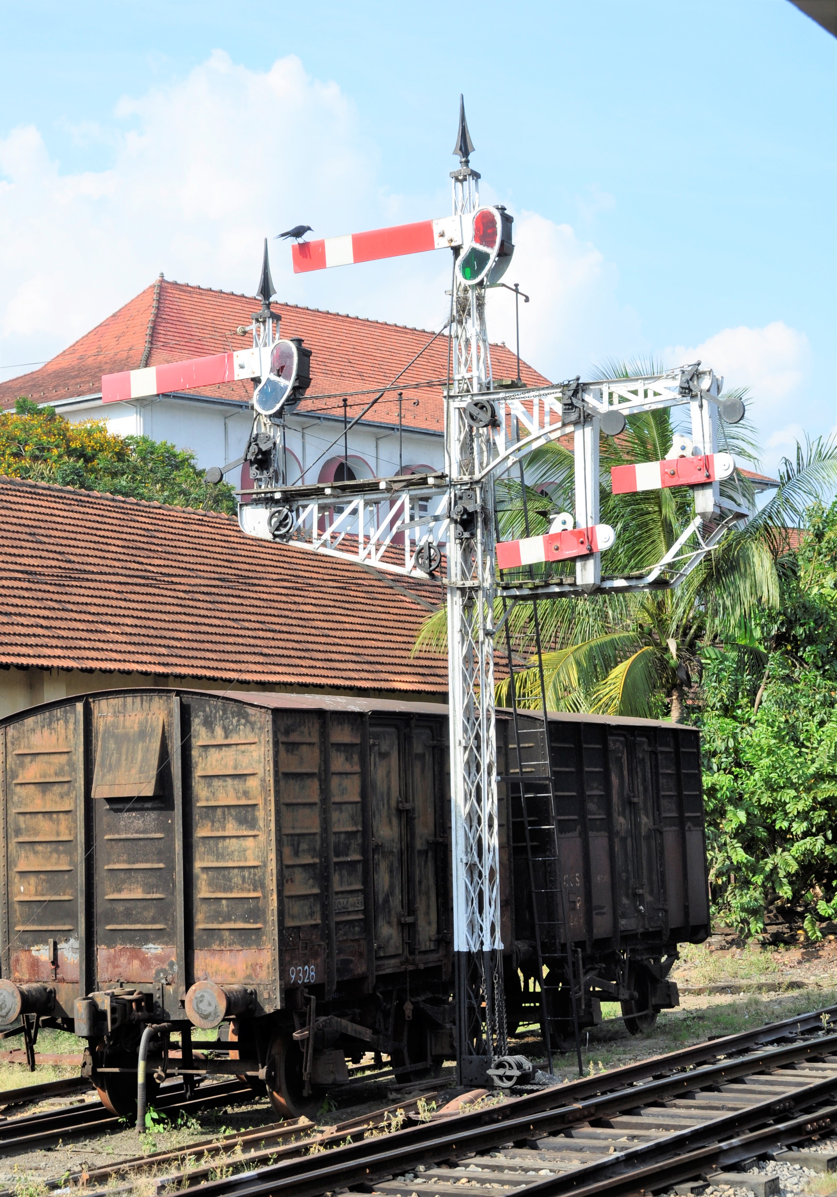
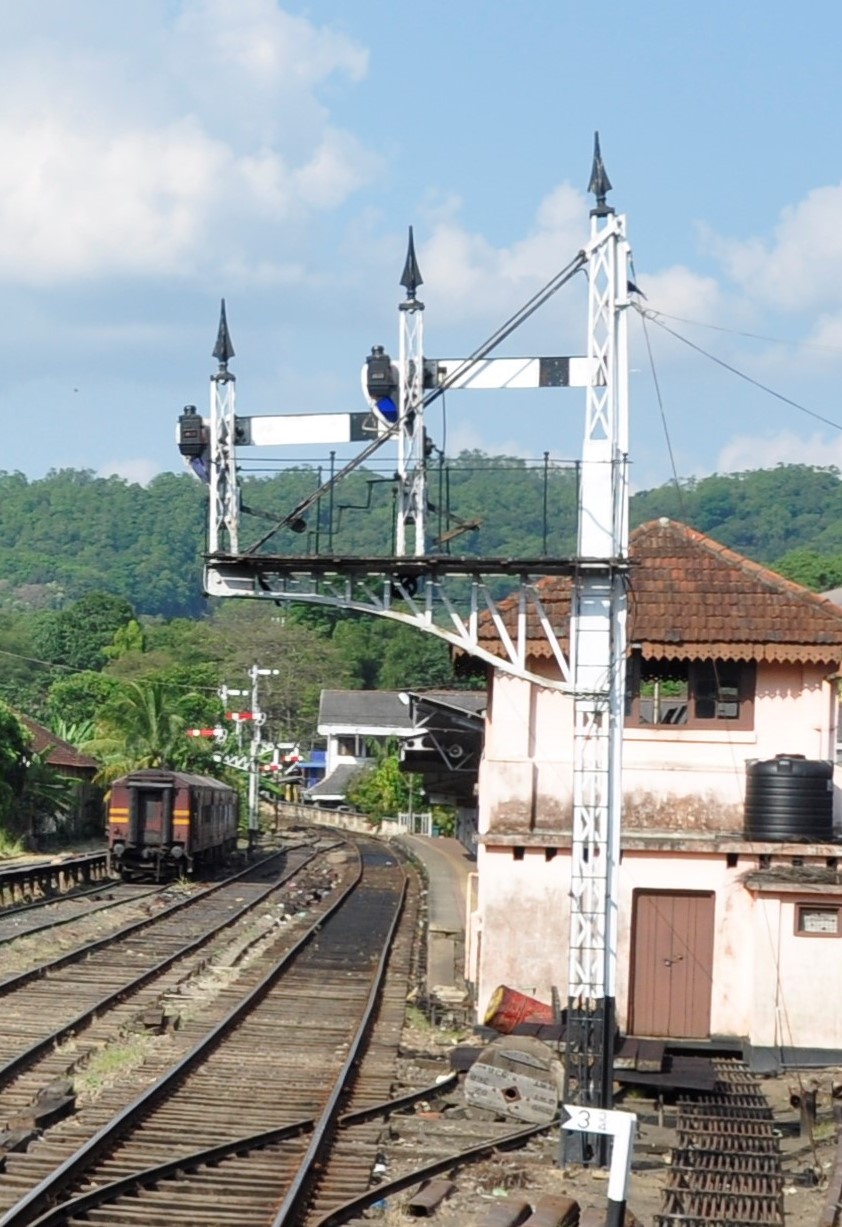
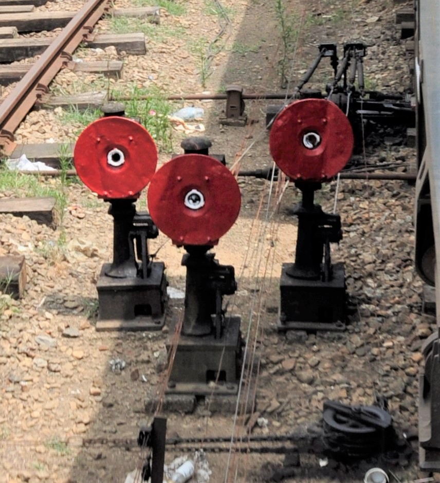
One of the joys of Sri Lanka’s railways is the retention of widespread railway relics from times past – in particular the signalling. Whilst there are modernised sections, substantial sections are still firmly in the first half of last century with full semaphore signals, tablets and block sections. Although a few arms have been removed, the bulk of the installations are still in situ and largely in use; so it is a bit of a cornucopia of signalling. Here are a few of the signals that I saw:
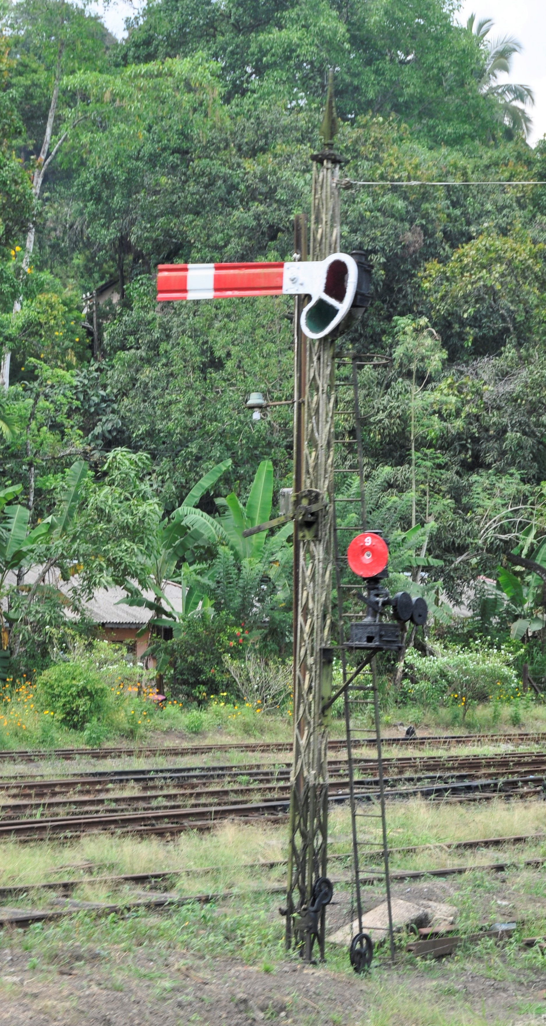
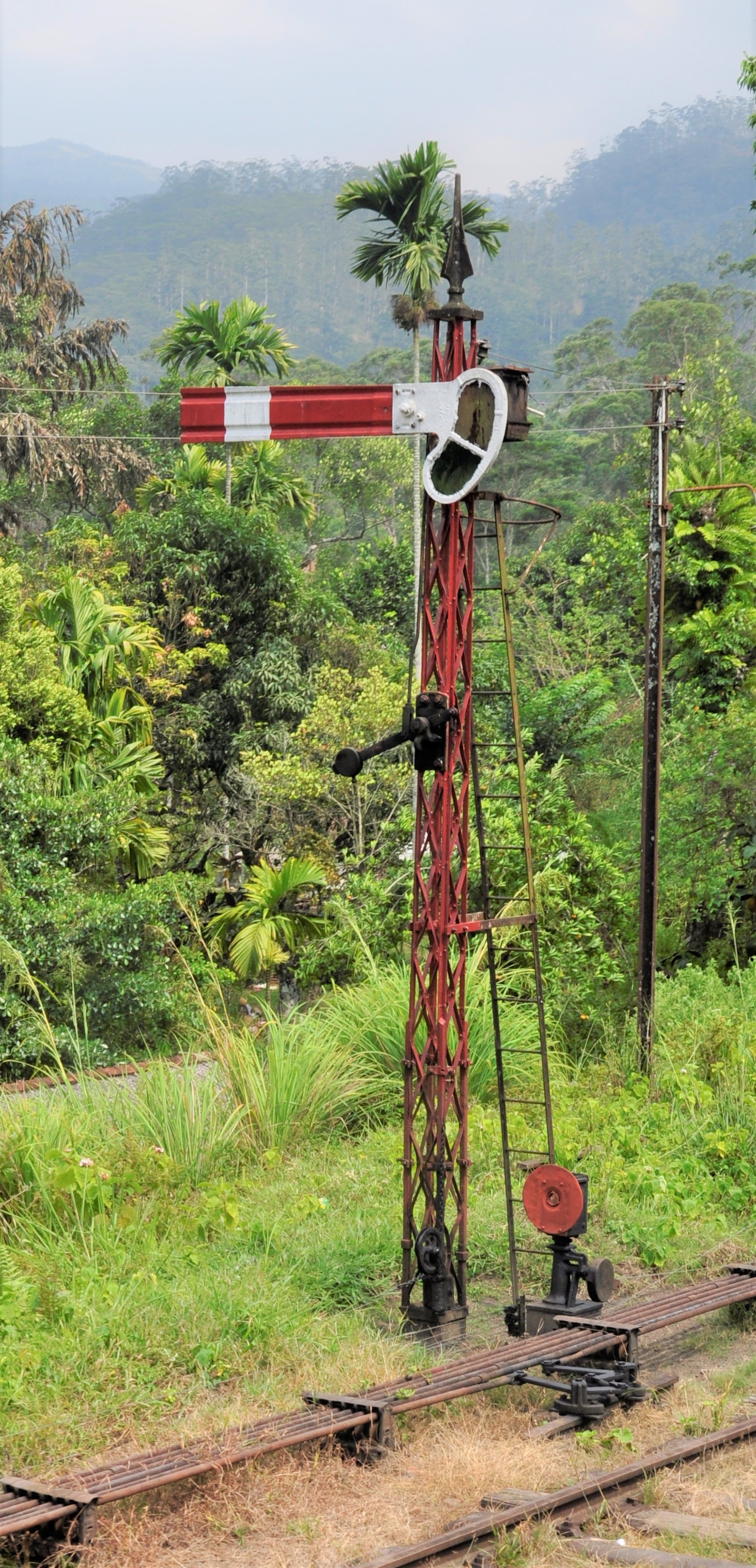
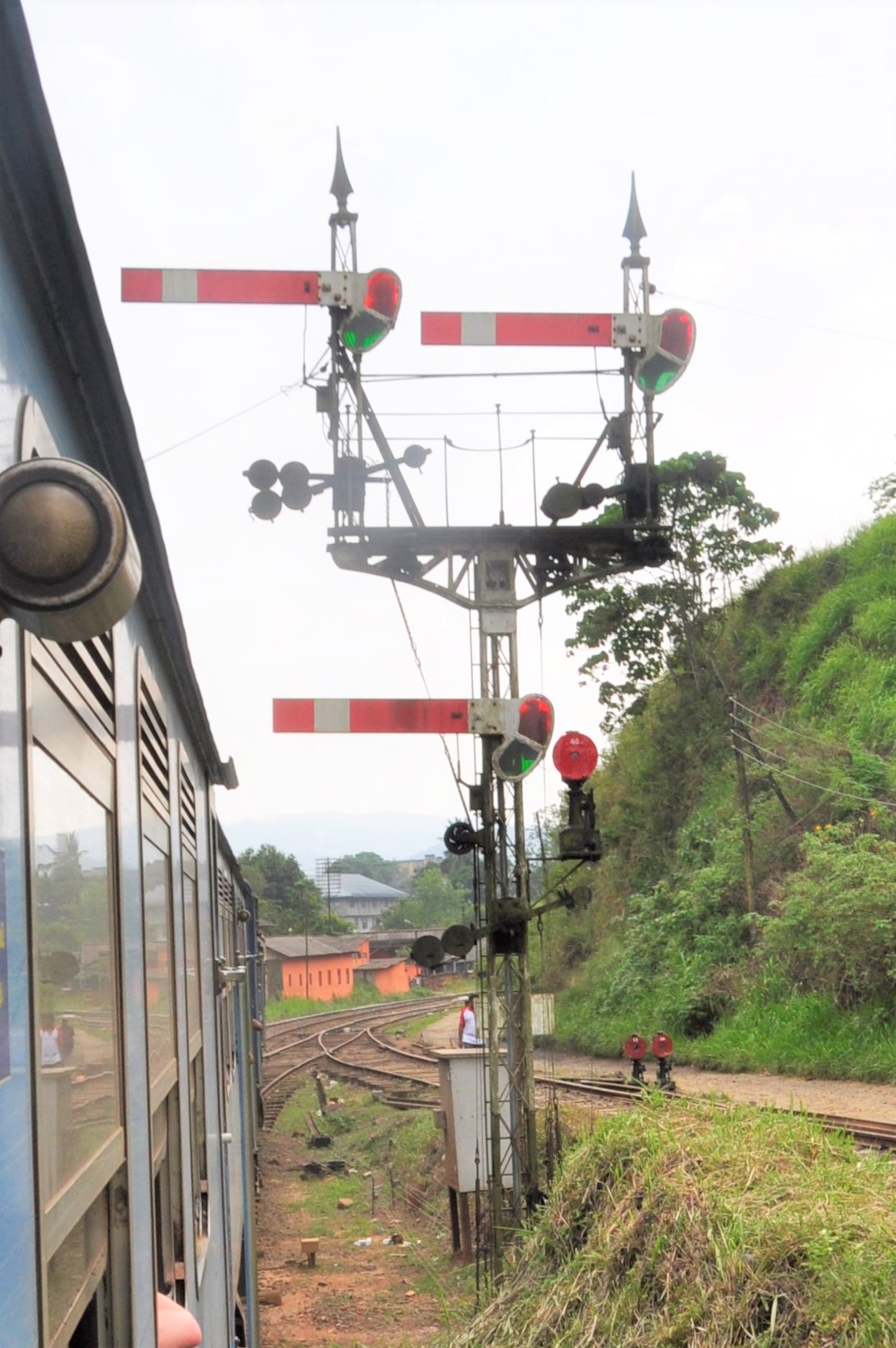
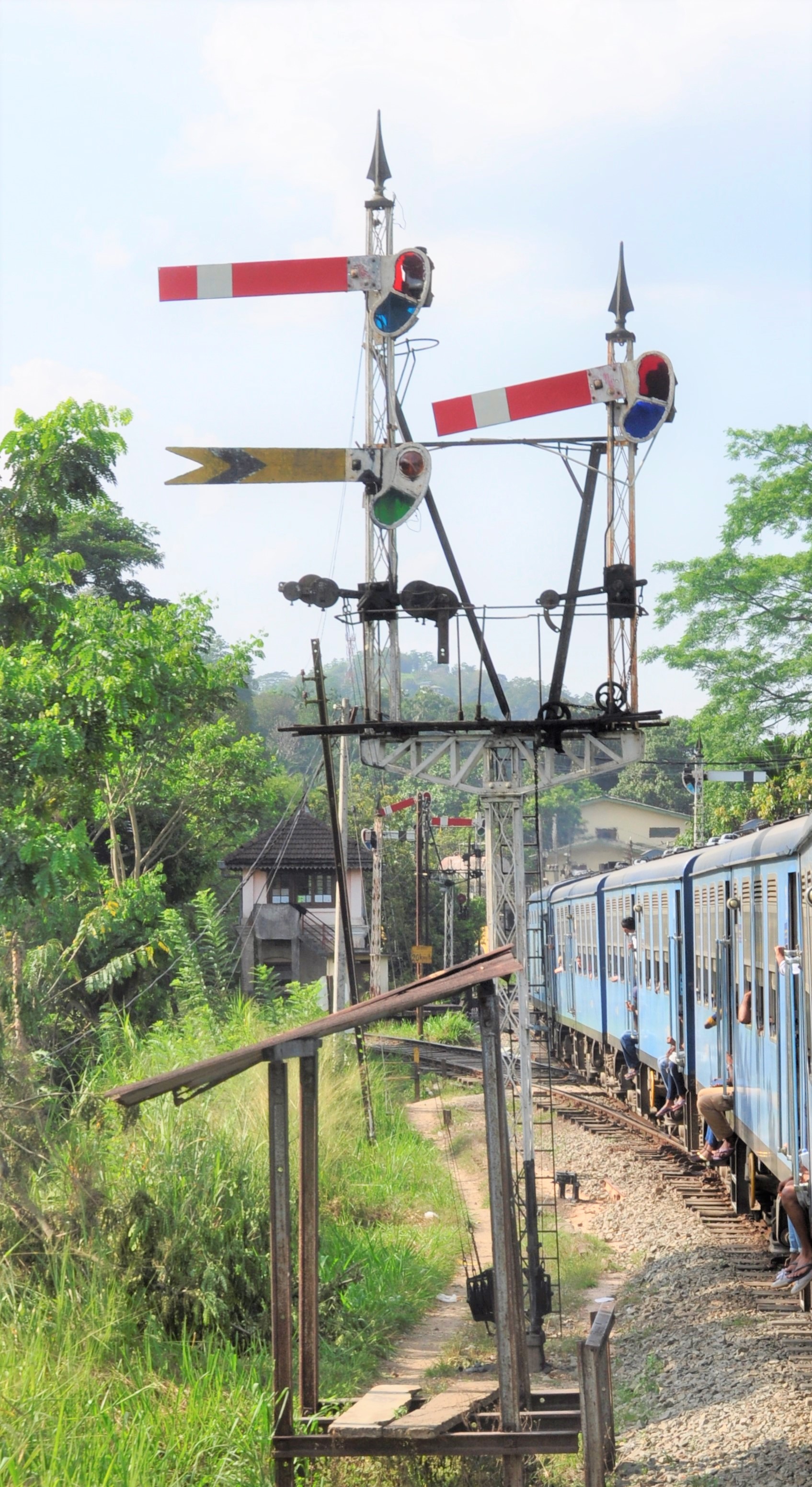
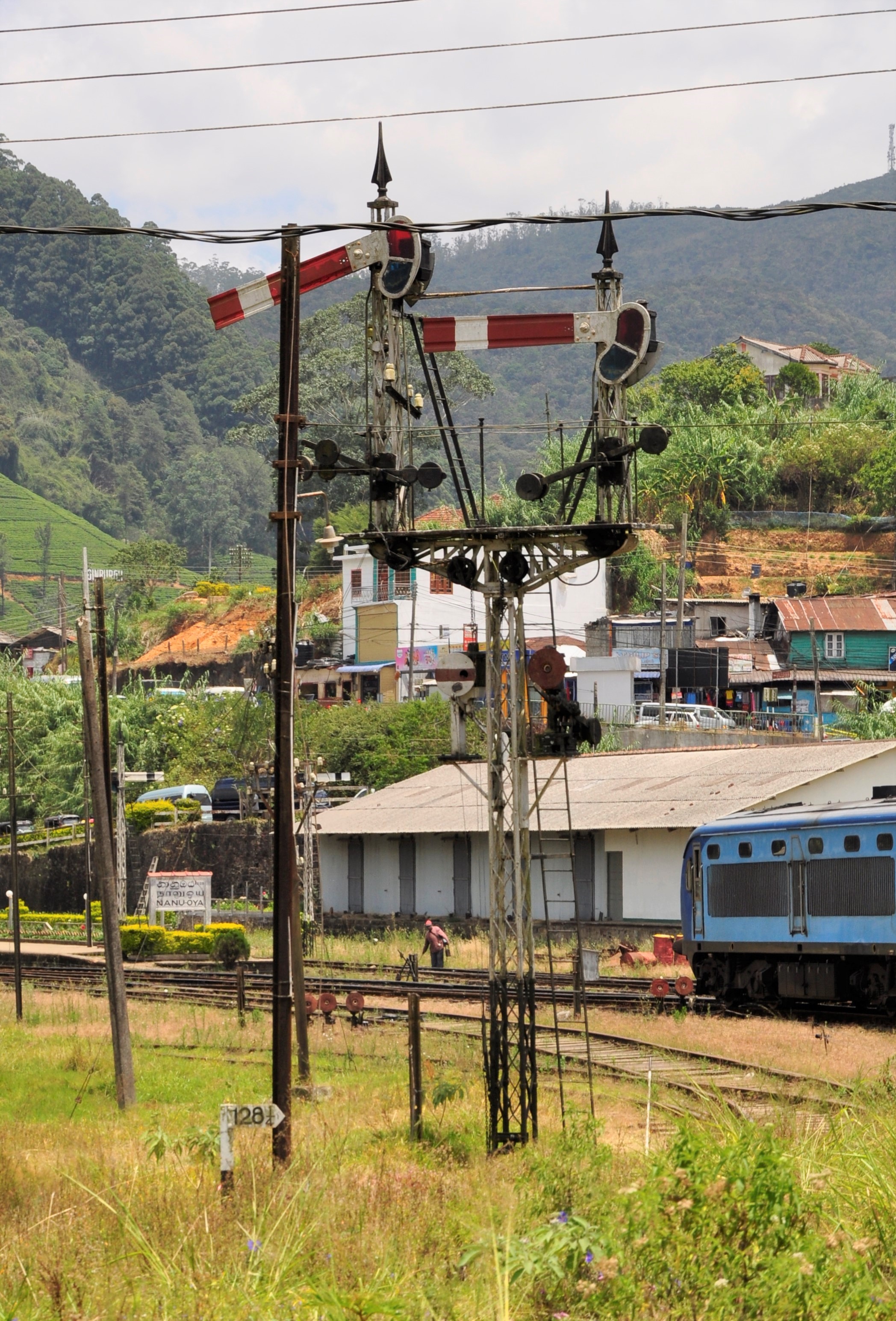
The signalling that I saw was all Saxby and Farmer – I only saw a couple of the lines in the country so it may be that there are other suppliers in evidence. The ground signals were quite similar to the McKenzie & Holland equivalents and tended to come in batches – looking like sentinels from an episode of Dr Who!
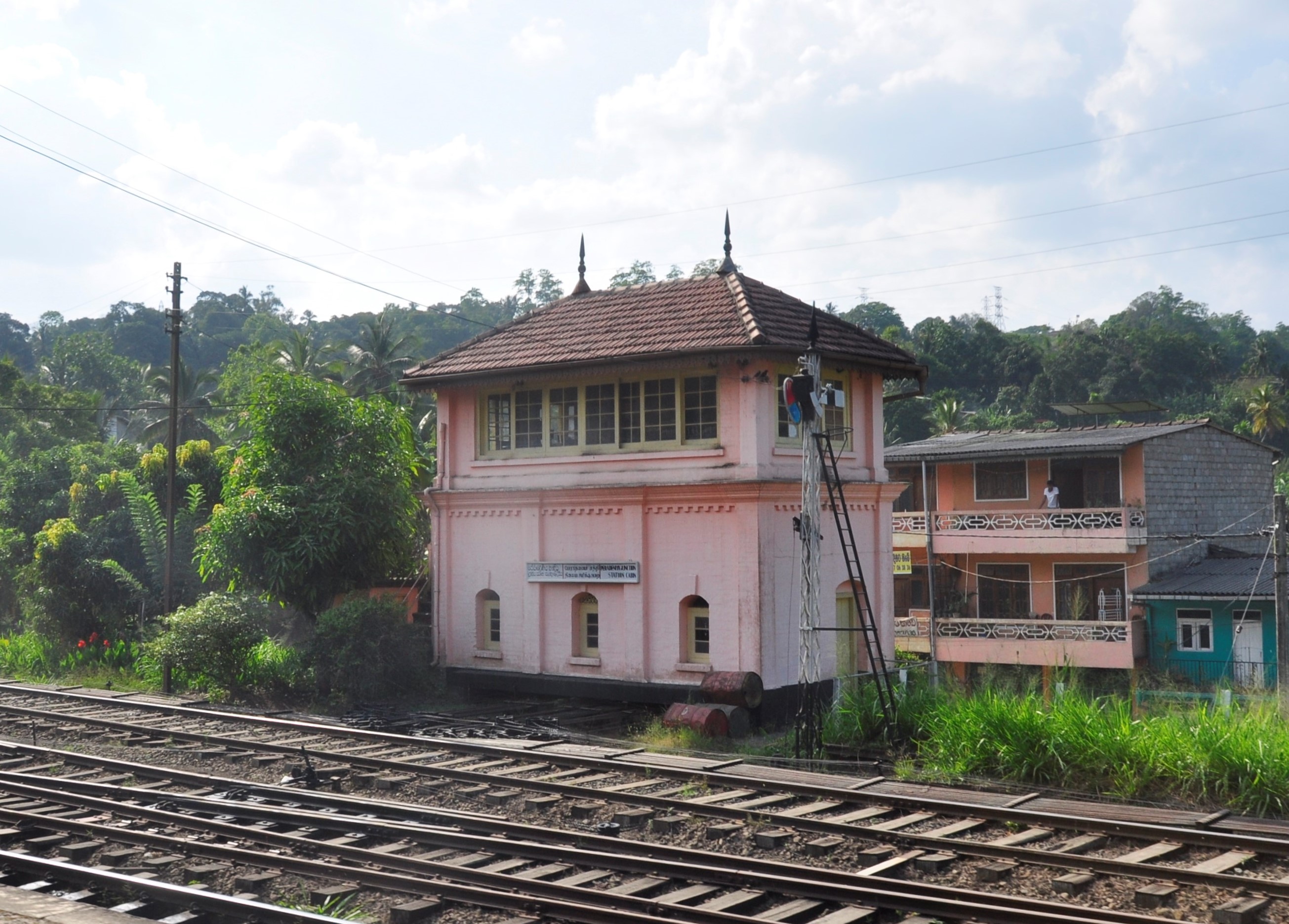
I thought the signal boxes looked decidedly home counties, although the rather shocking salmon pink wouldn’t have been found in Hertfordshire or Surrey I hazard!
With the exception of the signalman’s attire, the inside of the signal box was instantly recognisable to any UK railwayman of the last century of a half (well perhaps any UK railwayman of the last 40 years would be surprised to see so few white levers………).
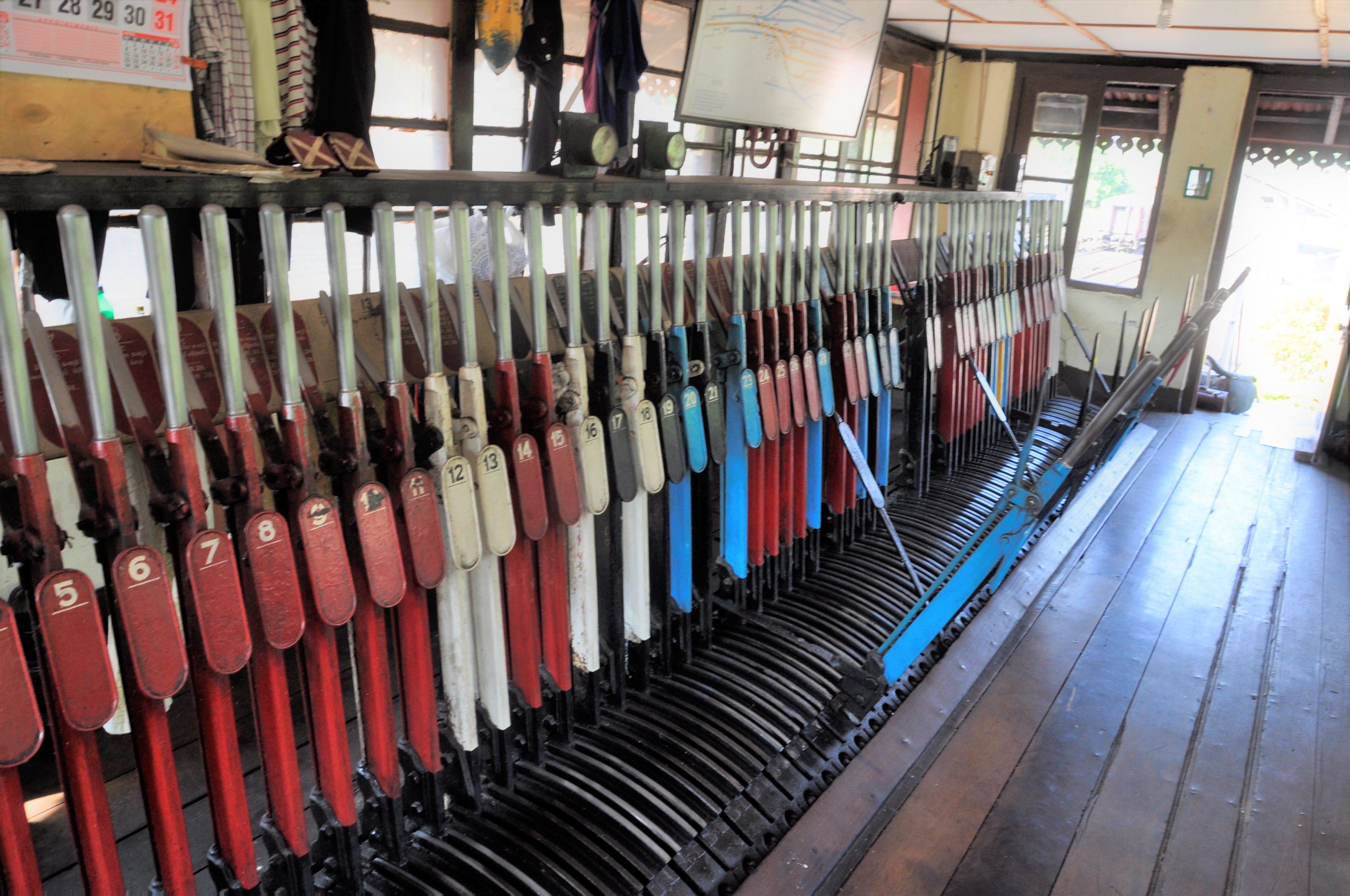
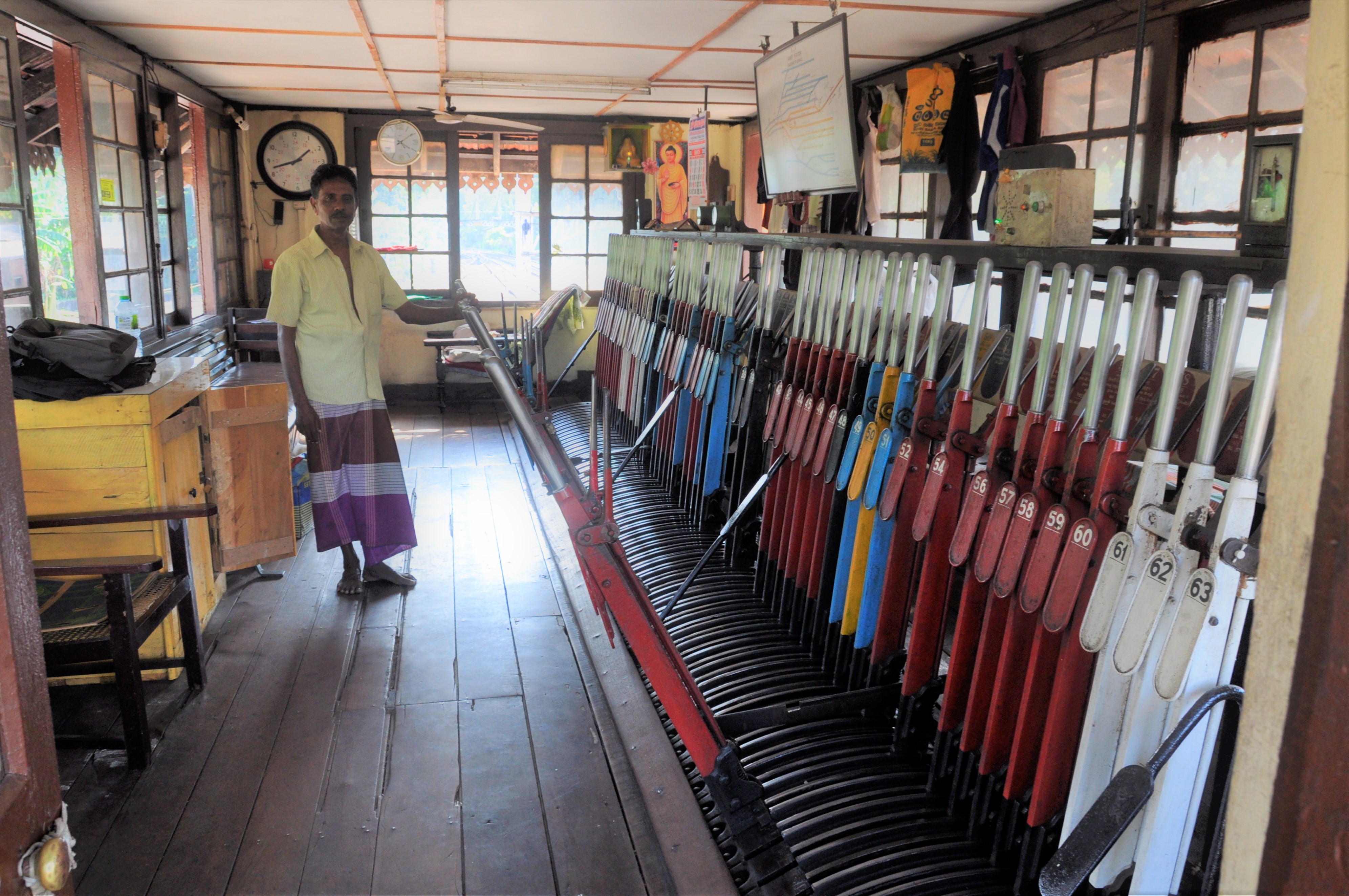
This is the inside of Kandy’s signal box. Kandy is largely a terminus with the line from the Highlands and Columbo meeting here, along with a branch. With five platform faces and only moderate amounts of sidings, it struck me as a perfect modelling track plan if anyone wants to have a go! Here is the view from the steps of the box, along with the signalling diagram.
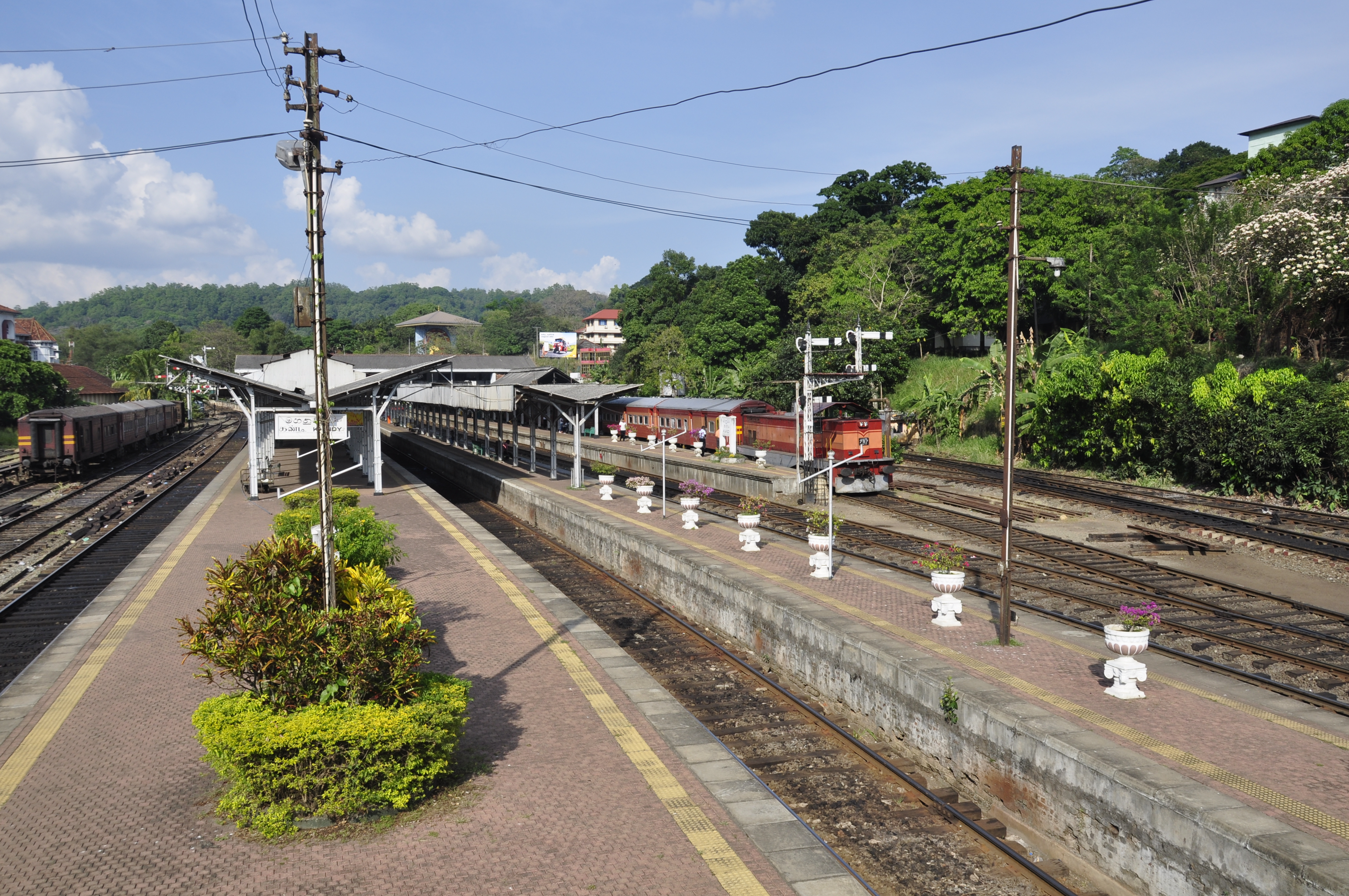
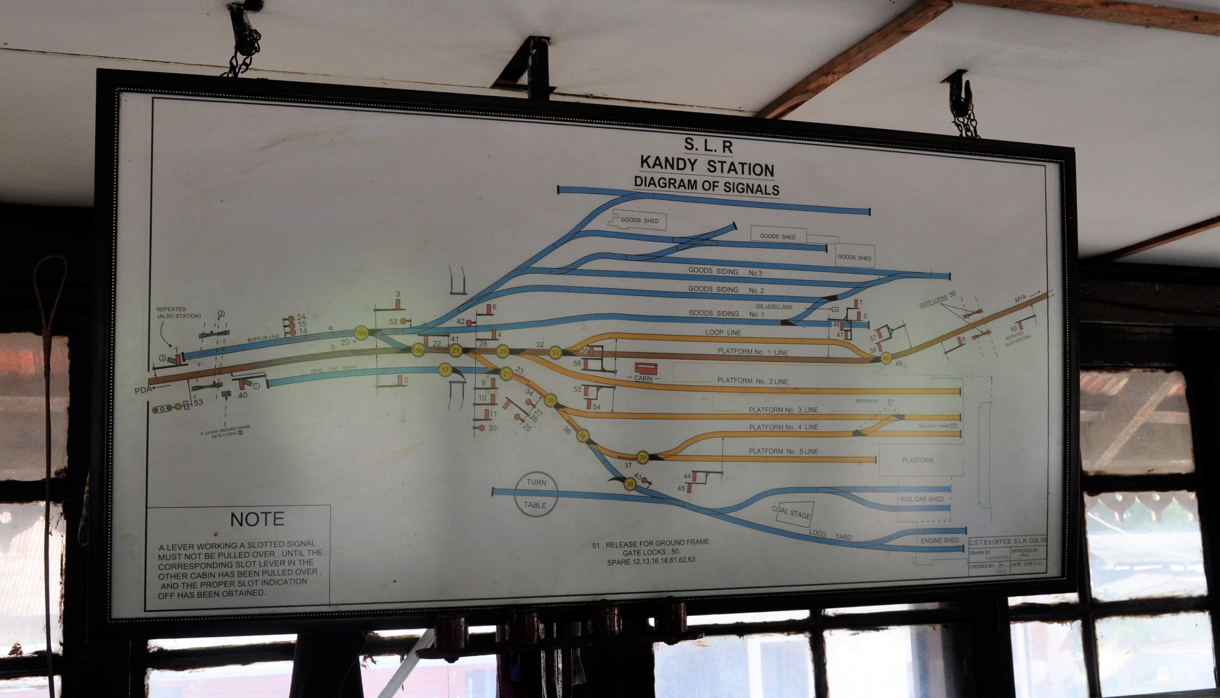
The approach to Kandy was in the process of being doubled when I visited, so I suspect that it will be resignalled with colour lights when this is done – so you had best get there soon if you want to see it like this………….