Category Archives: Workbench (stock)

Highland Railway – Cradle Bolster
A long time ago, I showed that I had conceived a design for a pretty unusual vehicle in the Highland’s fleet, a cradle bolster. They gave this diagram no 25 and it has a square cradle that sits on the top of a fairly simple body. The cradle had four bolsters protruding from its corners and I anticipate it was used in conjunction with another bolster with the cradle rotating to allow the load to twist on curves. I presume it was conceived to support long but more flexible loads such as thin sheet steel/iron than a traditional bolster wagons could cater for.
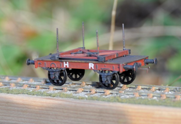
As this was my first attempt at designing vehicles, it is fair to say it went through a fair few iterations (or was that irritations!) which does largely explain why it has taken so long to complete from the first build – but it is now done and it looks pretty smart I reckon! It is really small in reality – being dwarfed by other even relative moderate wagons!
The second main complication has been as a result of the need to source castings for the axlebox/springs. I have used the Highland Railway Society’s but these do not come with attached springs (by design, so that they can be combined with differing springs to suit different situations). They are also not conceived to accommodate bearings sliding up and down within them and need to be ground out from the rear to make a slot for this. This makes them a bu**er to attach and therefore I am in the process of sorting out my own masters to overcome this problem. Once these are complete and I have got some castings done, I will produce a run of these for sale. So watch this space! I am also taking a look at the realities of scaling this up to 7mm, so also watch this space (but probably for longer before you will see anything!).
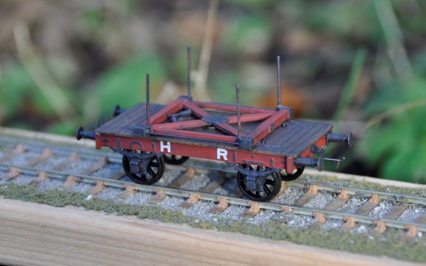
The error that I have had pointed out to me is that the bolsters ought to be tapered and now that I know this they do jar somewhat, so the next one will need to have this sorted out. As they lasted into well into the LMS days, there will be a second one and the one shown here will appear from time to time on Benfieldside jostling amongst the NER stuff!
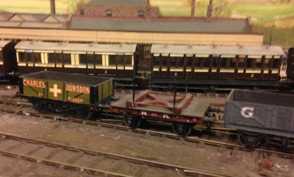
When I first embarked on this build, I thought that this was such an unusual subject that I was going to be building the first model example ever. A rather foolish notion that was upset by a visit to visit Buckingham a couple of years back where I see Peter Denny had modelled one (it is believed he was friends with Hutchinson, who had measured one up in the 1930/40s) – as you can see below. I have subsequently found out at least two others who have scratch built their own, so clearly I will need to search harder for originality!

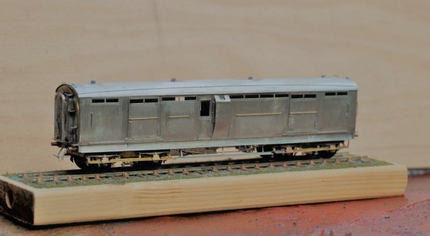
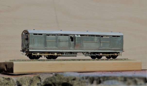
Midland Six Wheeled Full Brakes
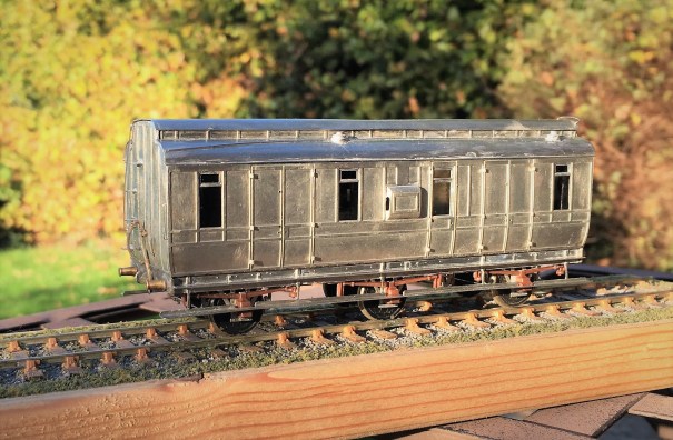
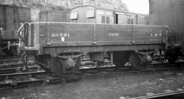
Although not Highland vehicles, these full brakes have a strong association with the Highland’s branchlines in the post grouping years. Once the LMS took over the Highland’s system in 1923, they seemed to have been horrified by the state of the coaching stock that they inherited! Portions of the Highland’s fleet were speedily retired and large numbers of foreign company’s stock was drafted onto the system (especially the main line from Perth to Inverness, where the trains became fully corridor connected almost overnight).
When it came to the branchlines, the upgrade came primarily by the cascading of the better Highland stock onto these lines but there were exceptions. Although the Highland had full brakes, it was a line that had a lot of parcels/packages traffic, so it seemed that they needed even more and a batch of these Midland six wheeled full brakes were drafted in.
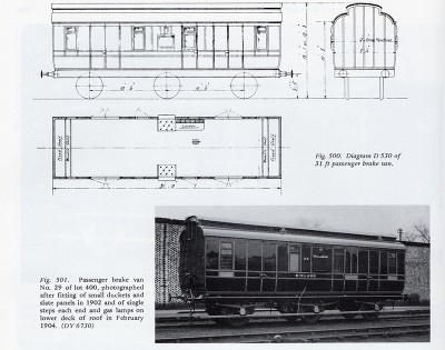
Many photographs of the Highland branchlines of the 1920s had one lurking in the background so I felt one should get to make appearances on Glenmutchkin. Simple, I thought, Slaters do a plastic kit for one and whilst it is no longer available, it is easy to pick up second hand and it should be a nice quick build. Unfortunately, I had not realised what a rubbish kit it was! It is too short and too narrow, most of the mastering is really crude and the panelling in particular would be a scale 6 inches deep. So the Slaters kit made it back on ebay only marginally quicker than it came off and I set about designing my own kit.
It has taken a couple of iterations and about three years, but finally I have got to the stage where I am happy with it but you can form your own view!
The first iteration used a cleminson chassis but in the light of the success I had with sliding axles on some of my other 6 wheeled stock, I redesigned it to include these and some sprung W-irons in the style of Bill Bedford’s.
This proved similarly successful and as you can see in the video, it trundles along quite nicely!
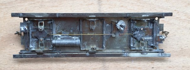
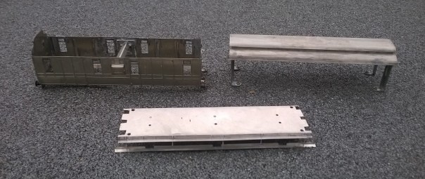
Other than the use of these sliding axles, the main unusual feature of the model is the arrangement of securing the roof. I have found that it is essential to bolt these in place to prevent the roof becoming adrift at some point in the future (which has happened to half my stock over time). Therefore, I designed a set of legs that allow the roof to be bolted through the floor from below and in the process also securing the separate chassis tight too. Broken down, the components look like this and having them separated does make painting a lot easier. It is definitely the route I will take in the future.
It is intended that this kit will be made available for sale as a 4mm/1ft model – albeit you will need to source the fittings/castings yourself. I have prepared some fairly extensive instructions (see link below) and this includes the details of what is required and where to get it from. I am waiting for a quote from the etching company to be able to work out the sensible cost for these; so an update post will follow when I list it on the Miscellany Models site.
Miscellany Models Rolling Stock 2 – Midland dia 530 Full Brake v2
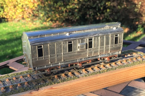
In the meantime, here are a couple of additional views of the completed vehicle, awaiting its turn in the paintshop!

Cornish Modelling and the Demon Barber of Fleet Street
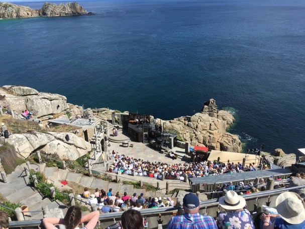
Don’t worry – this is not announcement of being turned to the dark side of modelling “Green With Rivets” (aka the GWR)! Instead it is a reference to a week’s trip to the extreme west of Cornwall to support my wife who was appearing in a musical that was running for a week at the Minack Theatre – more of this later……
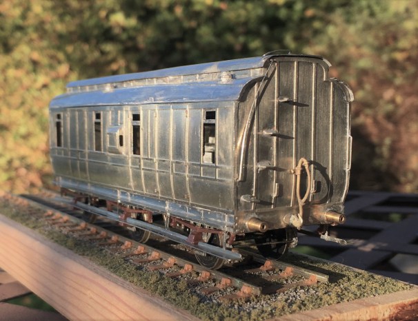
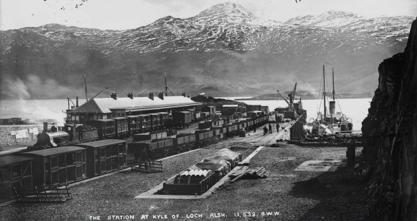
As I was expecting to have a degree of time hanging around whilst the Mrs was on stage, I took a little modelling with me – in this case, a Jones era double deck sheep van. As can be seen in this George Washington Wilson photograph of Kyle – sheep traffic was an important source of traffic to the Highland Railway – the majority of the train in the platform are sheep vans and there is also a row of them in the foreground.
Ever with the eye to efficiency, the Highland developed a double deck van to double the number of sheep that could be transported in one vehicle. I believe that the Cambrian Railway and several railways in Ireland had similar vehicles, but otherwise these were characteristic of the Highland’s lines to the west coast and clearly I have to have a rake of them. Unfortunately, there is quite a lot of effort in each one………….for example each side below is made up of five layers of laminate (and they are delicate too)!!
The highland had several versions of these vans, this time I chose the second era of van, which has a single door and diagonal bracing; I do have plans for some of the other diagrams so this is a topic we will revisit at some point! The starting point for this vehicle was an etched kit from the Lochgorm range (presently unavailable, but we are all hoping……) and as already hinted, it is not an easy one! This is mostly due to the delicacy of the parts and the multi-layering of the etches that take up a lot of care to line up with each other. It takes a fair few hours simply to get the sides made up and ready for assembly and then you still have the metal bracing to do!
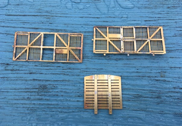
There were a number of elements to the kit that did not work for me. The various tabs you see in the above image are to help locate the various floors with each other but in practise they are not correctly located and just get in the way – so I whipped them off! I also ditched the compensated suspension and instead used spring suspension instead with some trusty Bill Bedford sprung units.
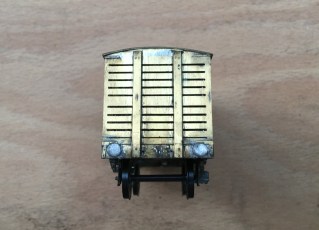
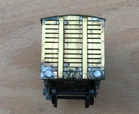
However, I did not spot the biggest problem until it was too late. There is an error with the design of the kit ends where one of them is missing the top gap between slats. The correct end is as per the right hand picture and had I have spotted this prior to the assembly of the ends, I would have been able to insert the additional gap with a piercing saw. Having missed the problem until after I had built the van, I decided not to sweat the parts apart to cut in the slat. It only shows to those that know it is wrong; the problem is that I am one of them so it does niggle!
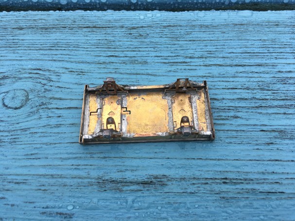
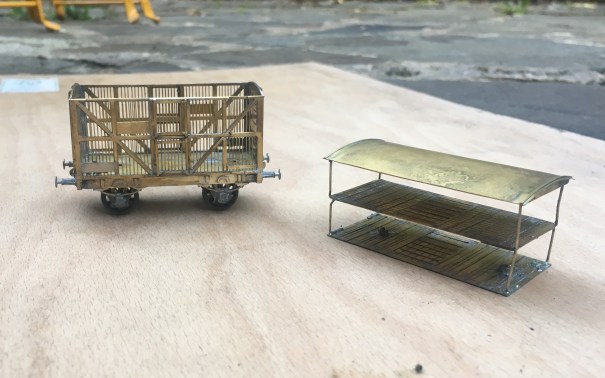
Contrary to the instructions, I did not loose lay the floors in place and instead created a cage arrangement by hanging the floors from rods that were secured to the roof. As can be seen below, this enables the roof and the floors to be released from the interior of the van. As with all my vans/coaches, this is secured in place with some bolts and nuts, so that the roof can be clamped tightly in place (I hate the cracks of doom that I see on otherwise fine models where roofs are not properly secured!). The detachable roof is necessary to both paint the vehicle but particularly populate it with the necessary sheep. You would be startled by how many sheep are required to fill one of these – around 50 and it costs a fair amount to populate each van. Thus, I have in mind casting some of my own in resin, although that is a story for another day.
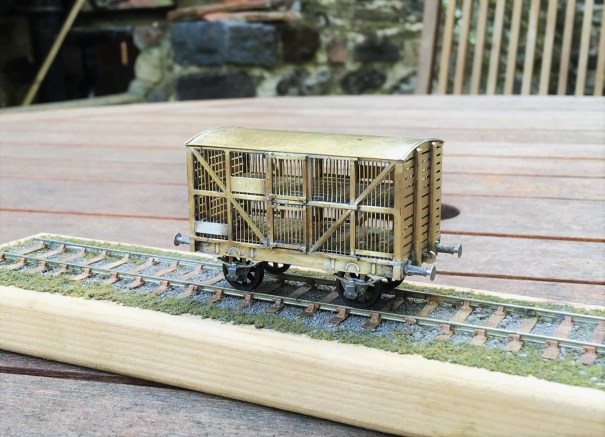
The problems with the kit did not finish with the problems noted to date. The iron strapping was not quite right, the springs for the axleboxes are too big and the brake lever/shoe seemed excessively skinny. Thus, these were all adjusted or replaced with alternatives. All this effort and problems to solve meant that the van took a great deal longer to finish than the week that I had available – so it has taken until now to photograph it. This is what it looks like and rather dainty and different I think it is too!
And what of the Minack Theatre? Well, for any that do not know it this theatre’s setting is simply breath-taking, being set in the cliff side only three miles short of Land’s End. As you can see, vertigo is an issue for visitors and all of the set, props and costumes had to be carried down to the stage level – exhausting work that took us three hours! One of other downsides of the theatre is that the seals, dolphins and basking sharks can sometimes be seen over the shoulders of the cast – which is distracting as you can imagine!
Only my wife was on stage, my duties including the stage building and front of house duties but with 7 public performances in five days, plus rehearsals there wasn’t that much time for modelling!

The musical being performed was Sweeney Todd – The Demon Barber of Fleet Street which follows the revenge that its namesake extracts on a corrupt judge and his beadle (with quite significant amounts of collateral!) for wrongly arranging for him to be transported. The most recent Hollywood version is pretty dark and definitely less watchable as a result – our version has just as death but with a great deal of humour too; especially as the leads had some pretty good comic timing to deliver it well.
The by-product of all these killings (ie bodies!) found its way into pies and one of the more jolly parts of the performance is where all the customers of these pies extol the virtues of their meaty dishes. So with apologies for my rather crude phone videoing; enjoy……………(I did, although strangely I had no taste for pasties whilst I was down in Cornwall!)………..

Clyde Bogie
The stock for Glenmutchkin has a recent addition and a rather beautiful one too.
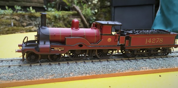
This is a Clyde Bogie; the prototype being designed by David Jones and delivered in 1886. Initially this was a top link locomotive of the line but as time went past it was relegated to lesser duties. On Glenmutchkin it will be one of the locomotives for the branch passenger trains – equivalent to what the real locomotive did at the end of its live. This particular example was the last in service and lasted until 1930 and, as you can see, it picked up the LMS’s first livery of fully lined Crimson Lake.
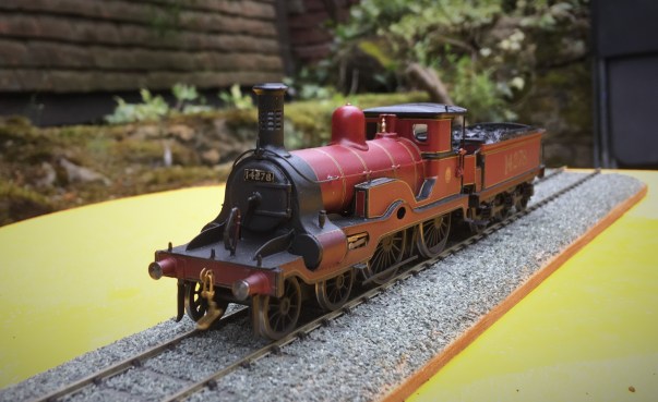
The model was built for me by John James from a Lochgorm Models etched kit. It is fair to say it was not an easy kit to master and John has cursed me a fair amount I believe for asking him to do this particular prototype…………… He would have cursed more if he also had to make the louvred chimney!
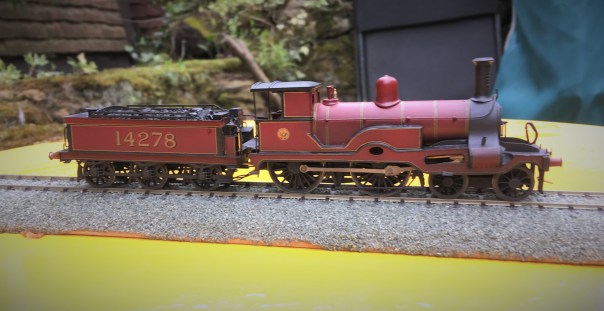
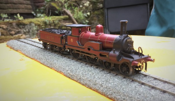
Since John has delivered it to me I have fitted a sound chip and some AJs. I need to fit some loco crew too before long. I suspect I am not going to find another sound fitted Clyde Bogie anytime soon as I have only ever seen one other built example so I can confidently say this is a first! I also seem to have disturbed the seating of the tender chassis as it is sitting rather low – a little task to attend to soon.
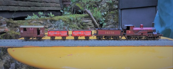
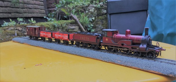
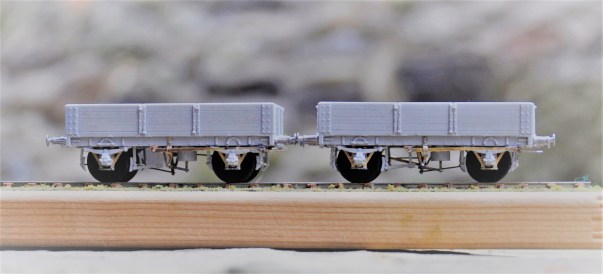
I have not been entirely idle whilst John has been busy and have been doing a number of little projects. Most of these will appear in future blogs but the pair of Wilsons & Clyde open wagons will not because this is effectively the same as the NB Jubilee Wagon I discussed previously. However, it is worth noting that Wilsons and Clyde were known to be one of the major providers of loco coal to the Highland so I am presuming these to be loco coal wagons.
And here is a picture of 14278 in action; albeit not at this point with sound fitted.

Dia 51 Test Build – Fox Heavyweight Bogies
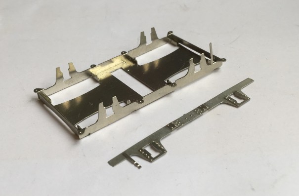
After the painting disaster, I have been working on the latest version of the Fox Bogies. The prototype utilised a patented design with pressed steel plates to form the sides and ends which produced a stiff and resilient frame, better than the other contemporary options. Thus these bogies were very common amongst the pre-grouping companies with most of using them to at least some degree.
Although there are several model manufacturers that produce Fox bogies, there are no versions that use springing which I now prefer. As they were the primary form of bogie used by the Highland Railway, I need a few of them and thus I have been putting some effort into getting a top notch solution. In this regard, I have been assisted greatly by Justin Newitt if Rumney Models whose design of sprung bogie has formed the basis of this.
The model has primary suspension on the pin points based on guitar wire springs,
In addition to this, the design has a sprung bolster, also based on a guitar string suspension.

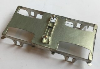
The castings I have used on these are from Lochgorm Models and the design has been conceived to enable these to be used either retaining their dampers (the cylindrical appendage at the end of the leaf springs) or with replacements that are a little more defined.
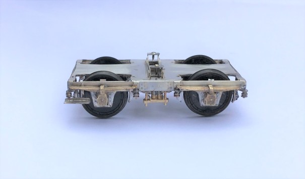
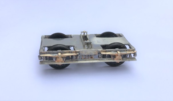
The etch is also designed to be provided with full stepboards as below or with only a short section to one end – as they typically were converted to during their life.
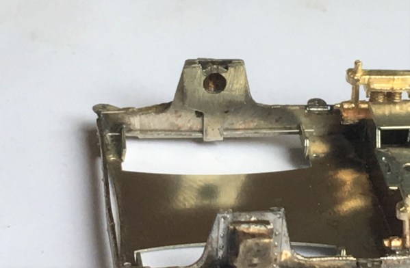
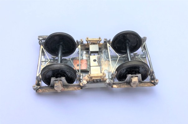
There is full brake gear provided, with a little trick where they do not pass under the axle (remember this view is upside down!) – this enables the wheel to be removed if this is required.
This is not the first version of these (don’t accuse me of not test building my designs!) and they are very close to done. The final change is to adjust the primary spring hangers slightly so that they are not visible when they are depressed (you can just see it poking above the sides in line with the axlebox), The advantage of computer drawn artwork is that things like this can be changed relatively easily.
These, and indeed the rest of the dia 51 full brake, will be made available for sale quite soon.
Previous parts to the test build can be found here:
- part 1 – the main body shell of the cupboard door version
- part 2 – the underframe
- part 3 – the second one, the sliding door version
Wordless Wednesday – because I can’t publish my word…………
I am not one to fall behind trends (!!), so I am following the “wordless Wednesday” trend of many people’s blogs today.
However, my reason for not putting down many words is that the ones I would like to write ought not appear on a public blog.
Thus I will have to settle with “matting agent” and “where’s the paint stripper” as my words instead……….
![IMG_0257[1]](https://highlandmiscellany.com/wp-content/uploads/2018/03/img_025711-e1521637806223.jpg?w=604)
The final installment of the test build sequence is a little further away than I had hoped!
Sliding Axles – A Reprise
Following my last post on sliding axles, I put the coach through its paces last weekend when Portchullin visited the Netherlands.
We I am pleased to say we did not have any bother with road holding it at all, even on Portchullin’s famously rubbish track – as long as you wait to the end of this clip you will see the proof of this. The axle has about 1mm play on the centre axle – 1/2mm either way – and this proved to be more than enough for the 4 foot curves on the layout. We did find it would be defeated by the rather tighter curves on Horselunges which was nearby but as these were down to around 2 feet radius, I don’t feel guilty!
The one issue I encountered was that as the axle slid over, the wheel rim would touch the side of the W iron and thus electrify it. This lead to some shorting issues if it came into contact with a vehicle of different polarity (I know it shouldn’t but well it seems to do for my stock!). Thus, for the next vehicle I will look to insert a layer of very thin copper clad paxolin below the W iron to isolate it.
So even with this issue I consider that the experiment to be a definite success and for relatively short bodied 6 wheeled coaches this will be my standard approach going forward. This suits the Jones shorter 6 wheeled vehicle of which Lochgorm and Microrail have examples. I think the jury is still out on longer 6 wheeled vehicles and a further experiment is going to he required as I am still a bit concerned there may not be enough side play.

Sliding Axles
Six wheeled coaches are pretty and they are quite characteristic on branch services on the Highland system in the early 1920’s. The problem is that they are bu**ers to get to properly work because there is a tendency for the middle axle to rock on any raised sections of track or for it to fail to swing on curves. OO modellers can typically get away with this as those deep flanges do come in handy for it. P4 modellers, such as myself, have a tougher time of it and whilst I have built a couple of six wheeled coaches, the count that can master the trackwork of Portchullin is rather less than the number built!
Having got better over the years at getting things to run properly (still a work in progress mind…..) I have turned my attention again to some more six wheeled vehicles. The first one to write about uses a less usual approach to accommodate curved/lumpy track – the use of a sliding axle. Although this has been written up before, I have not seen it actually executed so maybe I am a first (or perhaps fairly near to the first to do so!) Actually, I have found it pretty easy and the completed vehicle manages my test track with ease, so it will get an outing on the layout next week.
This is how I did it……………

As I don’t have a lathe, creating the pin point axles is beyond me even though it would be a very simple bit of lathe work and this was one of the main stumbling blocks to trying this approach previously. Then I had an inspiration…………Exactoscale axles. These have a notional outside diameter of 1mm which I found to actually be about 0.96mm – even better as it is thus an easy fit to a 2mm brass tube with a 1mm bore! Tube in this dimension is readily available and can be purchased from Eileens or your preferred metal stockist. The first task is to remove the moulded plastic cosmetic inner axle which proved to be really easy as it came off very cleanly.

Alan Gibson wheels are structured around a 2mm axle (which again was actually fractionally below 2mm) and have a tendency to be a little loose, so popping them off was easy!

I cut the brass tube well over length and mounted it in the drill. Prior to inserting it into the wheel I ensured that the ends were burr free by spinning the drill whilst holding a piece of wet and dry over the end. Not doing this leads to the plastic boss getting damaged and the wheel being less likely to be perpendicular to the axle.

My pillar drill doubled up as a neat wheel press. With the brass tube inserted in the chuck, a wheel blank was laid on the base and the depression lever closed to push the tube into the boss. Even though the tube was to the full 2mm, I used a dab of superglue as this was inserted to ensure it stayed there. The first wheel blank was pushed approximately 10-15mm through the face, so that there was a good projection of tube beyond. This comes in handy when the second wheel blank is added as the projecting end can be held in the drill chuck so that the process can be repeated.

And this is what you get once the second wheel blank has been pushed onto the wheel blank. The free ends are then cut back with a piercing saw & file so that they project no more than 1/4mm.

A quick ream of the bore of the tube and the old Exactoscale axle can be inserted. It is a nice smooth but not sloppy fit and the tube can easily slide back and forth without a trace of effort.

There is nothing radical about the vertical suspension; each axle being supported on a Bill Bedford sprung W iron.
This whizzes very nicely along my test track, including where this has reverse curves so I am hopeful it will stand upto a proper test on Portchullin over the forthcoming weekend. If so, then I will adopt it for my future relatively short wheelbased 6 wheelers – specially where there are full footboards that restrict the movement of the any moving w-irons (of which this Microrail kit is an example).
So fingers crossed and I will report…………

Something Fishy…….
Fish was an important traffic to the Highland Railway and as a result fish trucks were one of their most numerous classes of wagons. Given that Glenmutchkin is conceived to be on the coast, fish traffic will also be an important feature on the model too. There is to be a line to an off-scene harbour, so that I can justify a significant traffic. I already have a shortish train of fish vehicles, mostly open trucks, but I definitely need more
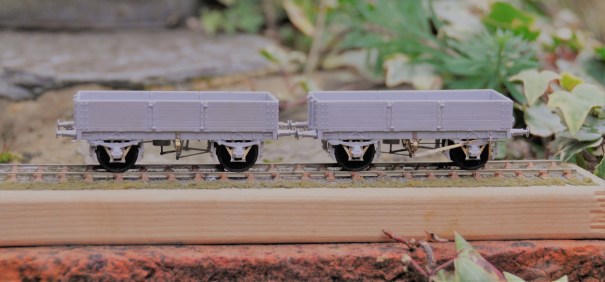
Back in April, I reviewed the Mousa Models LNWR covered van, which I was generally impressed with. Buoyed with this I spent portions of the last couple of weekends making a pair of the same manufacturer’s HR Drummond Fish Trucks. The kit is arranged for the variant that had a centre drop door, but there was an alternative variant with full length drop sides and at least some acquired morton brakes during their life. Thus, there are a few modifications that can be made if you wish.
The above is a full drop side version of the fish truck at (I think) Kyle (AB McLeod, HRS Collection).
Having built a few Mousa Models kits and however regretful it is, I was not surprised to find there were no instructions included in the kit. This is a pain as there is enough going on with the model to justify some guidance and anyone who does not have my father’s book will struggle. Unfortunately, I did not take any mid way through photographs before I realised that some notes on its construction would be of assistance, but hopefully these notes and the pictures of the completed model will be helpful.
A first issue I discovered was that the resin casting was a touch distorted. The ends in particular bowed into the well of the wagon and the whole wagon had a slight twist to it. This is a common problem with resin kits but with care can easily be corrected. Put the body casting in hot water – as hot as you can tolerate with hands (so less than boiling – 40C is about right) and it softens sufficient to allow these to be corrected.
Although the resolution quality of the LNWR van was good, the quality of the prints that formed the masters for these resin castings was not nearly good enough. Significant portions of them looked as if they were sand castings and did not look real. The body sides were better and were capable of being improved to an acceptable standard with some work with wet and dry sand paper. The solebars were worse, possibly because they received less effort to tidy them up prior to being used as a master. I managed to tidy it up a bit more in the areas that were more free of rivet heads, but above the W irons this was not possible and will have to be masked with some weathering.
The roughness of the print is apparent to the solebar
The kit is conceived with sprung W-irons to Mousa Models normal design – details of the assembly of which can be found in my previous blog post. However, these need to be carefully lined up to the bolts on the outside of the solebars as the locating slots to the underside are oversized and allow too much slop. It is also necessary to use the Brassmasters axle spacing jig to ensure that the axles are parallel and correctly spaced.
As I noted previously, Mousa Models seem to wish to use resin parts for as much of their recent kits as possible. There were only a few parts where this was a problem on the LNWR van but the problem is rather worse on these fish trucks due to the additional elements of detail that they contain. Had some of the components been produced as etched parts, they would have been a lot more durable without compromising fidelity. I replaced the brake levers, coupling hooks, vacuum brake plunger and brake tie bars with etched components or wire but if I were doing any more of these, I would also swap the brake blocks/hangers because I have managed to damage two of these. Masokits do some that are suitable, although there may be others too that I do not know of.
Page 147 of the carriages and wagons book shows a drawing of how the Drummond patent brake levers operated. In this, it can be seen that there was a long lever running to the right hand end from the fulcrum of the “scotch brake”. This then met a smaller lever that operated in a cam arrangement on the long lever but also connected through a rod to the other side of the wagon. On this side, there was another short lever (so appeared on the left hand end on this side). In the kit, the brake lever is rather crude due to the need to beef it up so that it is durable but even then it is very vulnerable. Furthermore, there is a second long lever, which is not correct at all. Instead, I made up a rod from brass and utilised an etch from the Highland Railway Society.
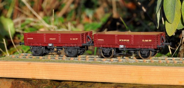
The principal side to the wagons, showing the missing brake lever now provided by way of a Highland Railway Society etching.
The patent braking system was, however, found to be unsafe because one side could be operated without the user on the other realising it (it cost someone some fingers, I believe) and the Board of Trade banned them for new construction. Therefore, many wagons had their braking arrangements changed, either by the use of full length levers and a ratchet or even a full change to morton brakes. I converted one of my wagons to the former by the use of some etched levers from 51L and an extra V hanger from the scrapbox.
And now the subsidiary side to the wagons, showing the Drummond Patent Brake lever to the left hand vehicle and a replacement long lever on the right hand vehicle.
I also took the view that the buffers were too delicate to survive in use and therefore swapped them for Drummond buffers available from the Highland Railway Society. I also found it necessary to cram the whole of the underside of the chassis with lead, to get the wagon’s weight to a level that would operate the wagon’s springs.
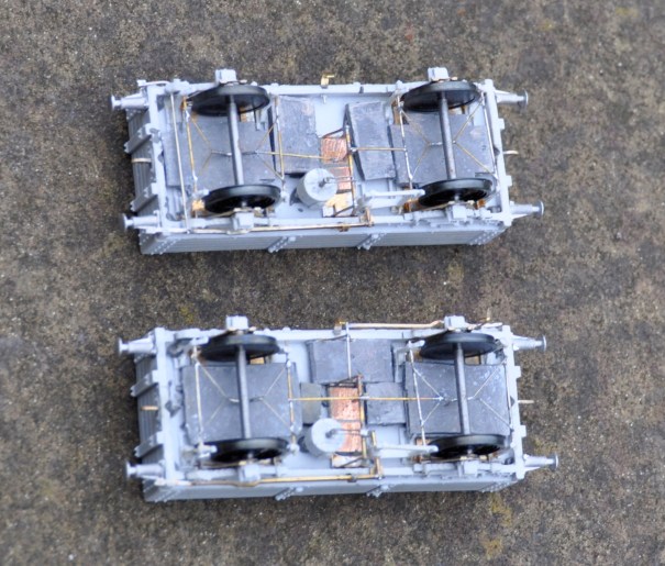
The underside – the rod to the Drummond brake is visible to the left hand end of the top vehicle.
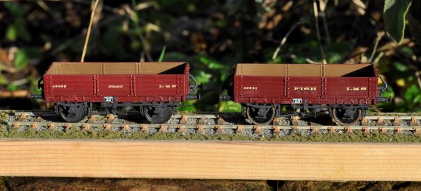
Although these will have been green with yellow lettering for much of their lives, I chose to do them in LMS crimson lake. Rather fine they look too! When carrying fish boxes, it is known that turfs were used to provide thermal insulation around the fish for the journey but my guess is that this was covered within tarpaulins. I have tended to find that the paper tarpulians (Smiths etc) are not that durable so I need to do some experimenting on alternatives – I do have something in mind. That will be for another post though!
Painted (well I seem to have missed the rims!) and awaiting weathering
All in all, these are quite attractive vehicles, very core to the required stock for Portchullin and the kits are a pretty good – but they could be better and easier to build if Mousa models had dealt with what are relatively obvious points.

Dia 51 Test Build Part 3 – and then there were two…..!
Following the first test build of the dia 51, I took account of what I had learnt from this and completed various amendments to the artwork. There was nothing truly major, so I was fairly confident that the corrections would get the model to the point where the artwork was done. But of course, to prove this, another test build was required and this is where we got to………..
And this is what it looks like……..quite handsom I think and certainly quite differnt from all the pother stock I presently have.
The eagle eyed will spot that the vehicle is slightly different in that this one has sliding doors, whereas the previous had cupboard doors. The kit is intended to cover both options and does successfully do so.
The ducket also has cut outs for a lamp at its head (a feature of Highland duckets). This proved quite challenging to model and I will avoid doing it again because it seemed to fall out of favour prior to the end of the Highland era so having only one or two would be right for my timeframe.
There remains a bit more work on the bogie to do; they can be made up to work very well but are a little more difficult to build than I had hoped. Once this is cracked, I will be making the dia 51 available for sale.
