In Praise of Cellulose Paint
A few months ago I was criticised for preferring to use cellulose paint when I spray; the concern being that cellulose thinners are aggressive and will damage the air-brush.
On the basis that I am of the view that “if it works for me” then I am going to carry on using it I am doing so. I am helped by knowing that I am not alone in my preference as Ian Rathbone also recommends it and also because I have not yet had any issues with my airbrush.
The reason I prefer cellulose is that it gives an amazingly smooth paint finish every time, it drys very quick and gives a very durable finish. Judge the former at least for yourself.
More on the model in a future post……..

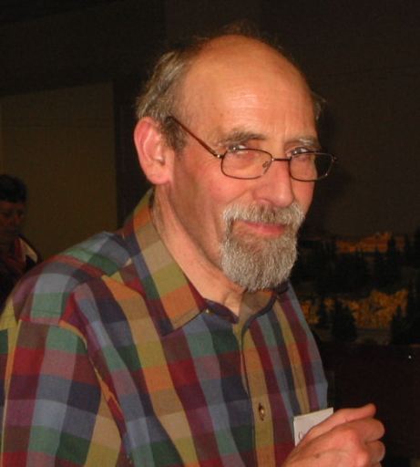
Richard Chown; 1941 – 2017
It is with great sadness that I advise that Richard Chown passed away last week.
Richard was a prolific modeller, typically of the somewhat unusual prototype and always in 7mm/1ft scale. Not for him a debate between BR blood & custard or blue grey, instead he modelled unusual and quirky prototypes from Norway, Ireland or France – that always made his models interesting!
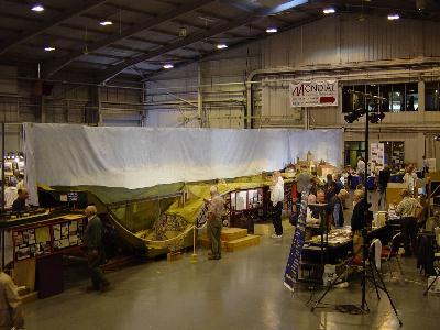
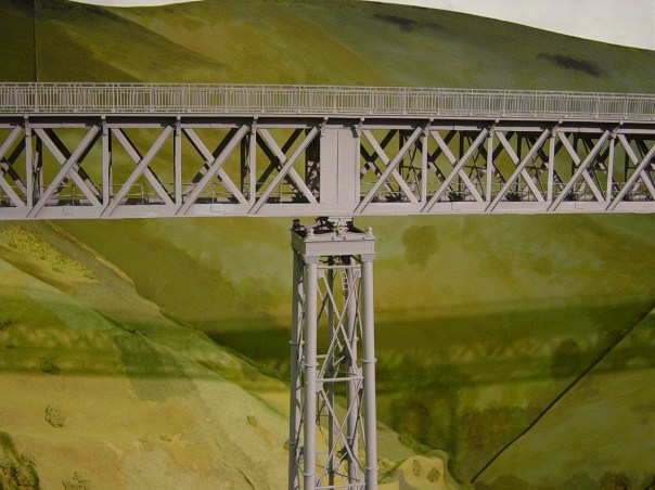
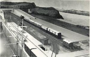
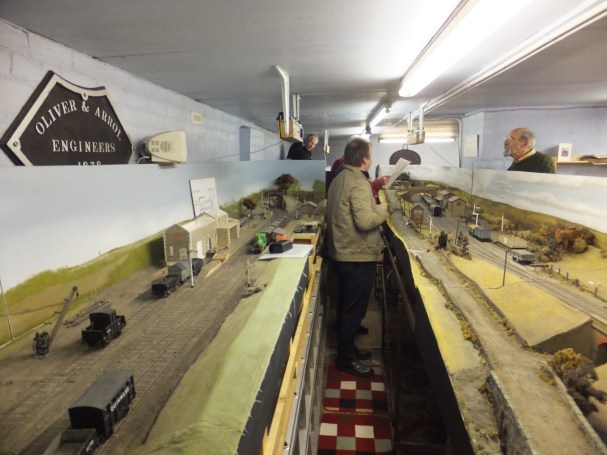
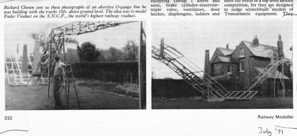
Although he did produce some smaller layouts, typically his layouts were somewhat on the large scale; tending from the substantial right up to a full size french viaduct where unless you were a basketball player you needed to stand on a box to reach rail height. This layout was Allendenac, which was based on a French line a touch to the north of Clemont Ferrand. The line was famous for the rather beautiful Rouzat Viaduct designed by Gustave Eiffel as a sort of trial run for the Eiffel Tower.
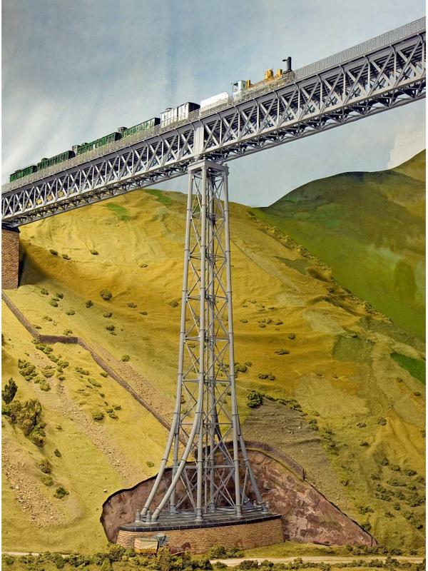
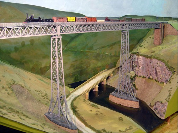
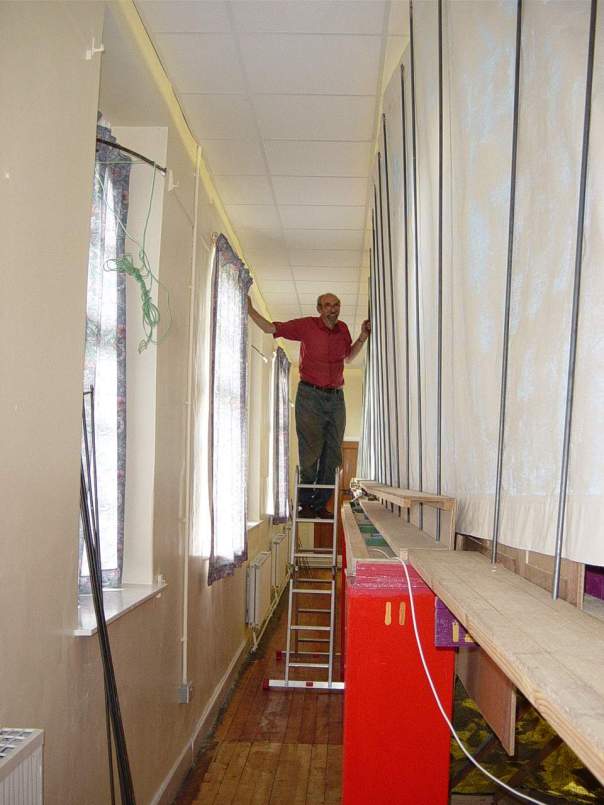
All being made in 7mm/1ft made for a somewhat large layout and to give a sense of its scale, in the picture below, all but the person directly in front of the viaduct is standing on a box and in the view below that, you can see Richard at the rear someway up a ladder and still not to the full height of the layout (so you see Mrs T, I am not that bad really………..).
With a layout of this size, access points to maintain (or build) the layout are important and here is Richard popping out of just such a hatch!
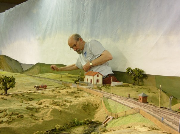
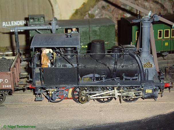
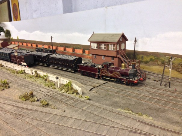
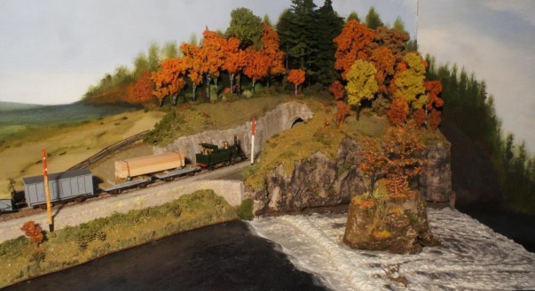
Just because the layout was big does not detract from how good the modelling was, as these pictures show.
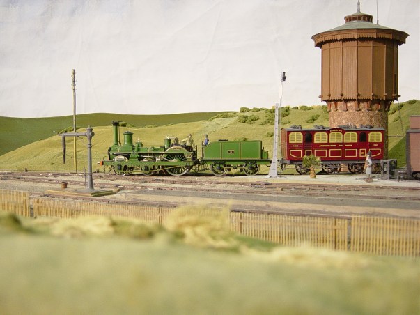
Naturally, as he modelled the esoteric Richard had to scratch build everything for his layouts and he was a very talented modeller as you can see ……..
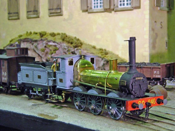
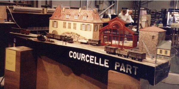
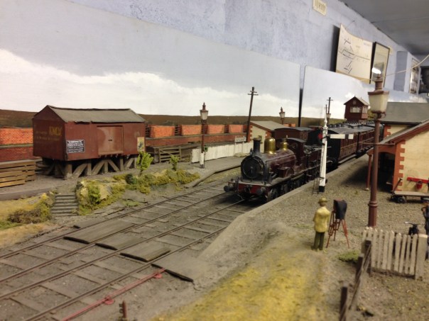
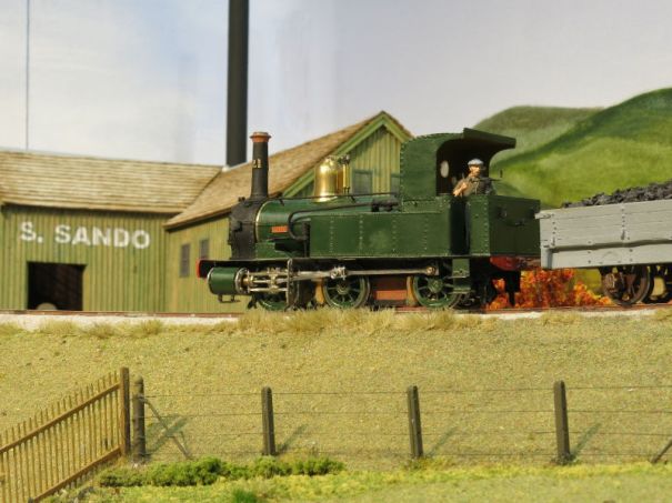
This locomotive operated on one of Richard’s smaller layouts, Courcelle Part which was built for a Gauge O Guild layout competition. It used some of the buildings from Allendenac and also its stock to create a more portable exhibition layout. As I understand it, Courcelle Part had some cut outs to the rear within which to place the operator’s wine glasses – the wine was often local to the Courcelle and Allendenac region as Richard felt that it helped the operators get into the right sort of mindset to operate a sleepy french railway. Now that is innovation in the field of model railways!
Richard’s own website (which is operating now but will presumably be taken down in time) shows that he was already firmly into modelling as a teenager and contributed to several group layouts.
His first layout that I know anything about was when he modelled the Highland Railway and built a full sized model of Kyle of Lochalsh – weighing in at a mere 48ft. Richard was, I suspect, inspired to follow the Highland by virtue of knowing Sir Eric Hutchinson and this interest brought him into contact with my father. Although the layout was exhibited and fairly well developed as a model, Richard became conscious of some operating restrictions of the prototype (but only because he did not know that the engine shed was used as a headshunt!) and lost interest in it. He disposed of it – apparently the under-bidder was none other than Roger Daltry!
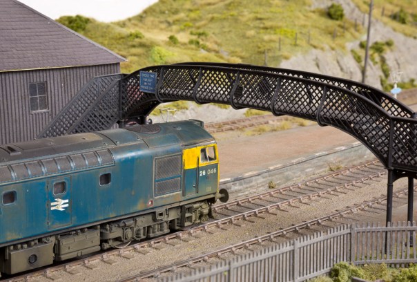
For me, however, Richard will best be associated with his layout Castle Rackrent; the name of which was inspired by a early 1970s property scandal. The origins of the layout are very modest as a small (for 7mm) transportable exhibition layout but it proved a crush in his small bedsit of the time. In an effort to find more room for the layout he found his employer accommodating (or perhaps unknowing) and erected it in a disused post office footbridge on Waverley station.
Helped perhaps by handy access during lunch breaks and the better part of a mainline station to fit it, the layout reached (I think) 70m in length before BR decided that perhaps they would like their footbridge back…… Undeterred, Richard had a house built with a conveniently large (a.k.a. giant) basement to fit it and subsequently extended it to some eight stations such that it was an entire system. The layout weaved around the room several times and even though the two stations below appeared next to each other, they were in fact nearly the length of the system apart.
All this (or nearly all in the final incarnation) was single line and worked with bells as no station could see the adjacent station and the trains had to be driven to the signals and then handed over. This made the operation of the layout somewhat unpredictable as I discovered at one stage when I had four of the six trains on the system within my station limits and a rather irate Slim Controller (you know who you are) sending urgent telegrams to discover the whereabouts of the hunt special…….
There are rather more photographs of Castle Rackrent in my earlier blog posts – here and here. The core of the layout – Castle Rackrent itself – was exhibited widely and on some occasions quite large parts of the system was transported to shows. Here it can be seen at the Ulster Folk and Transport Museum, Cultra.
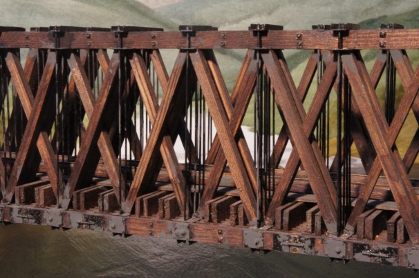
Richard’s final layout (that was completed, there were others in gestation) was Fangfoss which was built to Scale7 standards but of a 3’6″ gauge prototype in Norway. The layout was not an exact model of any location but was inspired by the Randsfjord line that was a little outside of Oslo and was a means of portaging past a series of rapids – in this case the Fangfoss.
As can perhaps been seen throughout Richard’s layouts he was keenly interested in bridges, often being the key part of his models; as in Fangfoss from which this detail is taken.
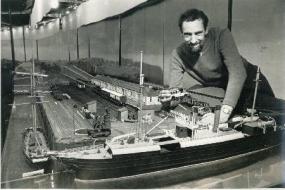
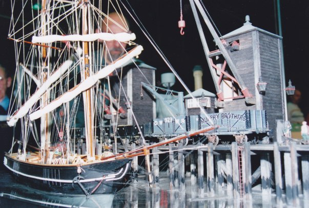
At the other extreme to the size of Kyle, Castle Rackrent or Allendenac, Richard also produced some cameo layouts, typically aimed at being transportable by train (he apparently took a large chunk of the Castle Rackrent system from Edinburgh to Bristol by train – back in the days when there were luggage compartments…..). Here is a small one called Port Lairge Wharf which was perceived as an extension of the Castle Rackrent lines (although I don’t think it was ever connected).
For finescale modellers in the Lothian Region, and occasional visitors from further afar like me, would gather on a monthly basis to operate Castle Rackrent and Richard was always welcoming and encouraging. He will be sorely missed by all and it is fair to say that I don’t think we will see the like of he in the hobby again…………….after all, who would try to model the tallest viaduct in the world in 7mm (even if sense did prevail on this one as it did not get completed)…….
Rest in peace, Richard.
Thanks to Jim Summers, Danny Cockling and Alan Aitken for the use of some of their photographs.

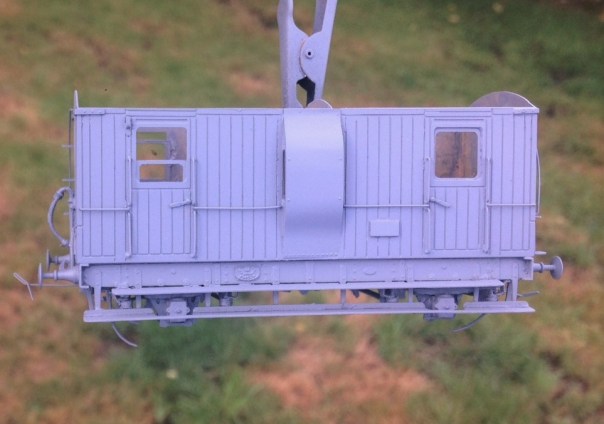
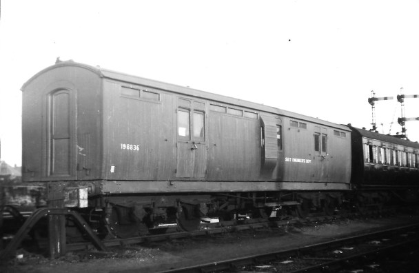
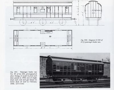
Dia 51 Full Brake – Test Build Part 1
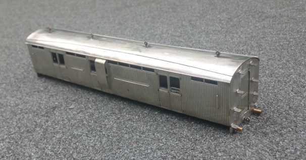
Following the last delivery from the etchers, it was time to get on and do the first test builds. First up was the dia 51 Full Brake. This vehicle was one of the later coaches from the Highland Railway and was of similar design to the cove roof corridor coaches that have been available from Lochgorm Models for some time. They were also amongst some of the last highland coaches to service as tool vans etc. This is what one looked like late on in its career after its corridor connections had been removed.
As with my efforts for the scrap tank, I am seeking to try and be a bit smarter with some of the kit design to draw together ideas of assembly of my own and also those of others. So starting with the ends, these will be made with a double skin to both provide the footsteps and, less commonly, some tabs to allow the sides to be secured to them.
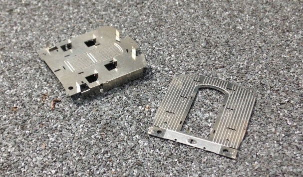
I have always found that too many etched coaches have flimsey sides that become distorted as they are made (or when ham-fisted me does anyway). Therefore, I have designed this such that the head and base of the side have significantly sized stiffening pieces, as can be seen below. These are designed to interlock with the tabs at the ends such that most of the locating of the parts is largely defined by the kits components.

Once the basics of the shell are together, this is what it looks like.
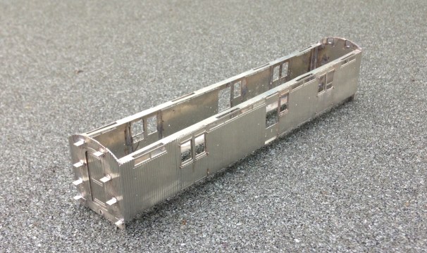
The roof proved to be one of the most challenging parts of the build. I had originally designed this with an inner to form the shape of the roof and then a thinly etched outer layer to go over this to provide the rainstrips and other detail. It proved too difficult to get the two to laminate well or even be rolled to a similar curve.
Instead, therefore, I ditched the outer layer and relied only on the inner. This had been half etched on the underside to assist its rolling to the curved profile. I found that it was still difficult to roll the roof due to the tightness of the curves at the extremity of the roof but by simply using bending bars it was quite easy to put the curves in with a limited amount of faceting. Faceting is where short straight sections with bends to the next short section that gives the impression of a curve. Once this was then filed on the outside to smooth out the facets, a smooth curve became pretty good. Thereafter, it was necessary to form the rainstrips with wire and file them back to square sections and as you can see, the effect is pretty convincing.
The underframe and bogies are to follow, in part 2.

The Ancient and Noble Order….
Back in one of my very first posts I explained the origins of the layout’s name; which has a lot more to it than might first appear (for any of you that have missed this post, follow the link back to discover the world of Glenmutchkin that Professor Aytoun created.
I had been aware that others had discovered the name and, like me, piggy backed a good story for our own purposes – there is even an entry in “Railscot” for the line. What I had not realised was that this seems to have been going on for more than 100 years!
This changed when I had an email out of the blue from a charity seeking to discover a bit more about the story and had come across this blog. Their email was prompted by a donation they had received of the medal below, which they were trying to find the story behind.

We have been able to find out very little about the medal beyond the hallmarking (Birmingham Assay Office in 1898) and that it was made by Shipton & Co (who are – as you will see if you follow the link – still trading. Our supposition is that, 50 years after the publication of the story, it was still known of and a group – perhaps a university society or similar – used the story to mark some sort of event or other action of one of their members by striking this medal. Given that Professor Aytoun’s story is centred on skullduggery and tall tale telling it is intriging to wonder what it might have marked!
So if anyone does know more about it, do please let me know and I will update the blog if any more information comes to hand.

Fastrack Finescale – Mousa Models Cast Resin Wagon Kits
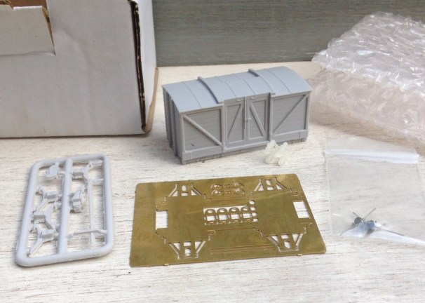
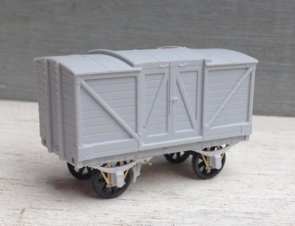
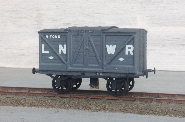
I have been building a couple of Mousa Model‘s kits lately; which has been a bit of a tale of the good, the bad and the ugly. Whilst the bad one will be written about in due course, this is the good one! The remarkable thing about it is its ease and speed of construction – so much so, I timed its construction just to see how fast I could build and paint it. The prototype is a LNWR dia 32 covered goods van, with a door to one side only but also with a roof door. This is the tale of its construction:
0hrs 1 min – Straight out of the box, the body & underframe are separate cast resin parts, as is the fret with the axleboxes, springs and brake gear. The underframe is an etch kit and the buffers are 3-D printed.
0hrs 15mins – The operational underframe has been folded up and fillets of solder run down the joints. Waisted top-hat bearings inserted in the bearing carriers along with the suspension springing wire. The first two carriers have been cleaned up and are inserted in the W-irons ready to receive the first wheel.
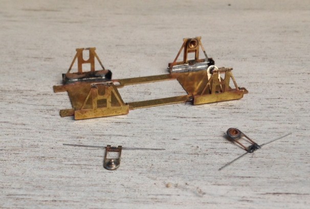
0hrs 25 mins – The remaining bearing carriers have now been fitted and the operational underframe has been stuck to the underside of the cosmetic underframe – wait 10 mins for the araldite to fully go off – so time for a cuppa!
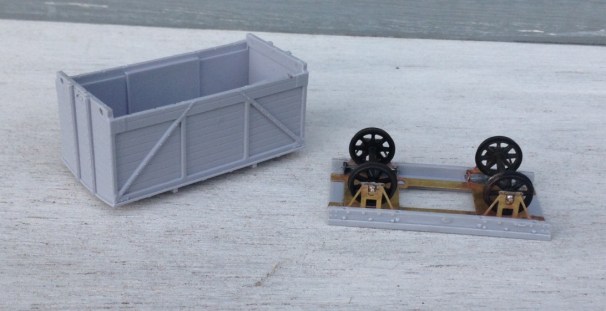
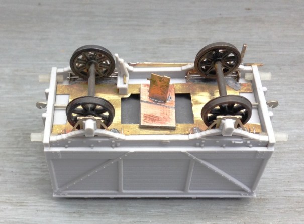
0hrs 45mins – the casting has been cleaned up to remove any casting burs/flash, which was apparent in small amounts around its base but actually the main casting was pretty good. The first two axlebox/spring assemblies fitted – but only after I opened up the rebate to their rear to ensure that the top hat bearings had room to slide and cleared away rather more flash. Being cast resin, the vehicles are pretty light so some weight has been added – 25g per axle is my rule of thumb. One thing I have found with vans is that the weight can detach so I tend to mechanically fix the weight too now, in this case with a couple of 8BA screws.
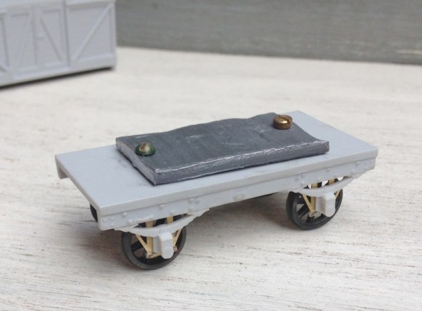
1hr 0mins – the second set of axle guards and springs now affixed, as is the body to the underframe. I decided that the bolt heads on the solebars were a bit too proud, so took them down a little with some wet and dry paper. A brake block has been attached – the kit provides a choice of timber brake blocks (for early periods) and cast iron – I went for the latter. I also decided, however, to cut away the brake lever as I felt it was both a bit too delicate to survive and also it was not quite straight. Instead, I provided a piece of 0.6mm brass rod to both help secure the brake block in place and to provide a mount for the replacement brake lever.
1hr 15mins – the buffer shanks have now been fitted (a tiny amount of fettling was required to the open the holes out slightly) and coupling hooks have been added. The kit does provide etched versions which I only failed to use as I thought I could save 5 minutes of the build by using Exactoscale hooks). A new brake lever and lever guard are etched brass from 51L models and should be more durable than the resin one provided in the kit.
Still 1 hr 15 mins – a piece of PCB has been provided for the eventual fitting of AJ couplings and I took advantage of this to provide a temporary bracket of metal to hold the model by during painting. A good scrub in warm soapy water, followed by a rinse and a second clean with a cream cleaner (washing up liquid leaves a residue, so I always do the final clean prior to painting with a cream cleaner) occurred next. So that is the model built in only an hour and a quarter, which is faster than anything I have built before – including converting r-t-r stock!
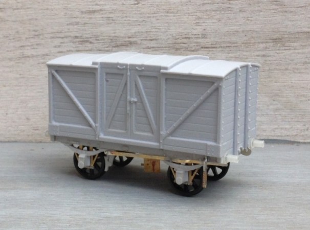
1hr 45mins – after masking the inside of the bearings, the whole model was painted in a mid grey – Tamiya TS 4 (German Grey). I thought this was about right for LNWR grey but as all greys of the time were lead based and thus darkened considerably over time, I tend to be quite cavalier about wagon greys! I did have a bit of an accident such that it ran on the roof but this was salvagable with a little bit of wet and dry once it had dried off. These paints finish to a semi gloss and thus are ideal for taking transfers, in this case HMRS Transfers sheet 16 in methfix because the vans were pretty archaic by the time that the grouping occurred, so I presumed that few would have been repainted in LMS livery.
2hr 15mins (but 10 mins of this was me correcting my messed up roof painting!) – ironwork below the solebar, the draw bar, buffer shanks and brake lever were all picked out in black. All then sealed with Testors dullcoat a couple of times.
So whats left? – I do need to weather it, some AJ’s need to be fitted and the “holding tab” will need to be removed. I am waiting to do a batch of weathering, so it will be a bit quicker; maybe 30 minutes for the vehicle. So I reckon this will be a complete, painted and weathered very good quality van or wagon on the 3 hour mark – well worth doing and no need to moan about when the r-t-r manufacturer is going to produce it!

A Promise is a Promise
Dad coming good with a promise…
In 2004 an eager but very flu affected 7 year old got himself out of a sickbed to drive with us all the way to York to see and ride behind the Flying Scotsman. Imagine his dissapointment to find that she had failed and was in for maintenance. The Black 5 on the Scarbrough Spa Express really did not work as a substitute – by 7, he had already seen a fair number of Hikers by then!
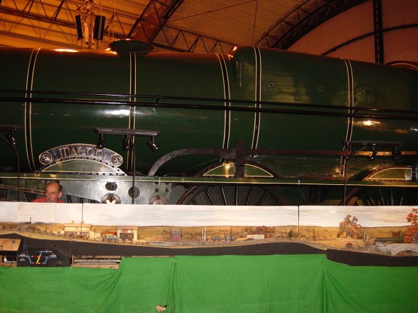
So I promised that we would get to see her again soon and definitely have a ride behind her…… well it’s just neither I or the National Railway Museum thought “soon” meant 12+ years (and the small matter of £4.5m)!!! But Dad has done his duty as you can see…… even if the thrill to a 20 year old had waned a bit in comparison with the 7 year old’s which is definitely sad!
So enjoy a one of my pictures of her ladyship (or money-pit as some beleive!) and with thanks to Brian Dandridge for all of the rest of them as we were on the train and obviously could not photograph ourselves!! Thanks Brian!


I have always felt the A3s to be one of the most attractive locomotive classes (although I do not like the german style smoke deflectors); if I were OTCM Oly I would be busy hatching a new layout plan……………..well maybe I am (……not, don’t worry but I do fancy an A3………..!)

Two Steps Forward and One Back
Having taken a few days off to make a long Easter break and absent the family for a few days, I have set about the wiring of the layout as it has laid untouched for too long!
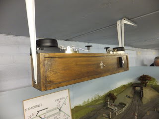
First things first was to mount the control panel and rather smart it looks too……….
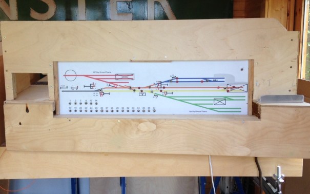
Control panel mounted in situ; a gap for the controller to the left and the aluminium strip to the right masks the power district switches.
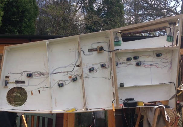
Then onto the wiring itself, which takes a surprisingly long time…………….this is only about 50% finished!
The two key boards to the station throat
One of my slightly better ideas (you’re about to find out about a less good ones!) has been to make up mounting pieces for the DCC Concepts Cobalt point motors. These are inspired by those designed for the Tortoise units and work on the same principal; they have a uniform mounting arrangement so once set up the actual point motor can be swapped over if need be without disturbing the set up. This is what they look like:
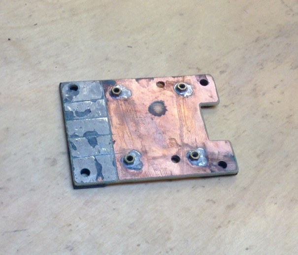
Cobalt Point Motor Mount
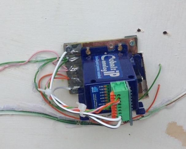
Nothing too revolutional, but I hope it will make changing these at exhibitions a lot easier as this is the absolute devil on Portchullin.
And the less clever idea? Remember the multigang sockets I had used on the control panels (link here) well they are not rated at a sufficient capacity to operate the point motors. I think this is because Cobalts operate on a stall basis (the motor doesn’t turn off, it just stalls when it reaches the resistance of the physical stop). My guess is that this results in quite high ampage draw and has led to the following:
The multi-gang sockets with burnt out sections to the left.
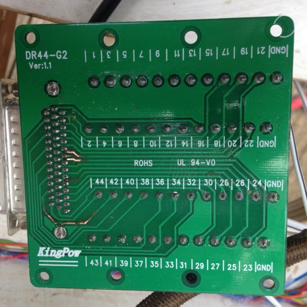
Ooops! Back to the drawing board (or rather traditional tag strip) for the linkage of the control panel to the board.
There have been other problems too; the carefully recorded wiring lists proved to be wrong on occassions so I have had to prove each cable run (dooh!) and I found one of the power district switches was defective (but only after a couple of hours of trying to trace the fault!)
So things are getting there, but we are still not at the stage of the first wheel moving!

Goodies – time for some more test building….
I had a delivery at work which was rather more interesting than the average box of lease documents I usually get…………it looked like this.
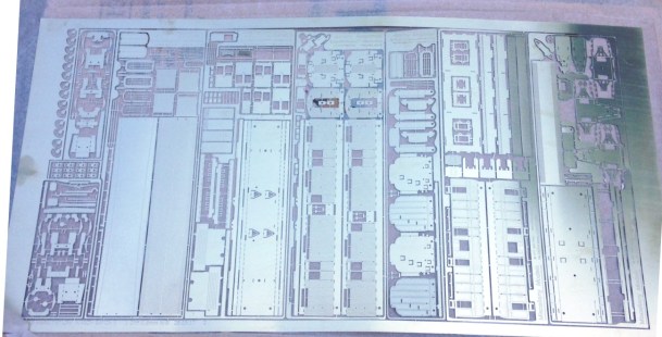
There are a number of items in this, some parts for some locos I have underway and an attempt to adjust the ECJS 6 wheeled bogies but the key goodies in this are a MR 6 wheeled full brake (to dia 530) and an HR bogie full brake (to dia 51).
The MR full brake should look like this:
and the Highland’s full brake here
So all I need is some time to do some more testing building…………..

Nothing to See Here
Well, that’s true of the top side, where nothing visible has happened of late but there is progress when you look underneath.
I have spent more than a few hours soldering dropper wires on about half of the track that has so far been laid. All is neatly colour coded (hopefully).

Another development in comparison to Portchullin is the painting of the entirity of the underside of the layout white. This is to make everything clearer and will, hopefully, make it easier to deal with issues with the layout set up – although I am hopeing for less issues!
Even more hours (weekends even!) have been spent making up jumper connections, so hopefully the wiring will speed up in the coming weekends! I have spent this time to work through the logic of the wiring across all boards and there is a full wiring schedule in place – none of the wonky logic on Portchullin this time!


Portchullin at St Neot’s – 11/12 March
Portchullin’s next outing will be this forthcoming weekend at the St Neot’s show:

Come along and see some noisy diesels like this? I rather hope to have a type 1 make an appearance over the weekend and any HR enthusiasts might wish to see a Barney put in an appearance (still in brass, don’t get too excited!)